Article

Circularly Polarized Asymmetric Single-Point Probe-Fed Hybrid Dielectric Resonator Antenna for Wireless Applications

by
NareshKumar Darimireddy
Department of Electronics and Communication Engineering, Lendi Institute of Engineering and Technology, Vizianagaram 535005, AP, India
Submission received: 6 November 2024 / Revised: 3 January 2025 / Accepted: 7 January 2025 / Published: 16 January 2025

Abstract

:
This paper presents a hybrid dielectric resonator antenna (HDRA) for circularly polarized (CP) radiation at 5 GHz, designed for WLAN applications. The antenna features a single probe feed that excites a combination of a circular ring patch and a cylindrical dielectric resonator (DR) element, achieving stable gain across a wide bandwidth. The parametric analysis and vector E-field distribution of the proposed antenna presents the optimization, and it is evidence of CP radiation, respectively. The hybrid DRA has a reflection loss (RL) bandwidth of 485 MHz, from 4740 to 5225 MHz, and an axial ratio (AR) bandwidth of 150 MHz, ranging from 4950 to 5100 MHz. It achieves a peak gain of 7.03 dBic at 5 GHz, making it suitable for missile tracking, data link communications, and IEEE 802.11n WLAN systems. Measurements of a prototype in an anechoic chamber show a close match with simulation results.

1. Introduction

Hybrid dielectric resonator antennas (DRAs) represent cutting-edge technology in modern wireless communication, combining the advantages of dielectric and microstrip antenna designs. These antennas are especially useful for applications like wireless local area networks (WLAN), satellite communication, radar, and various broadband wireless systems. Known for their compact size, cost-effectiveness, lightweight structure, and compatibility with standard transmission lines, hybrid DRAs effectively meet the critical demands of today’s communications landscape, where space and performance efficiency are paramount.
Interest and research in dielectric antenna technology have surged over the last two decades, driven by the need for antennas that offer wide bandwidth and ease of integration with diverse feeding techniques [1]. Microstrip antennas are commonly used, due, in part, to their relative ease of production. However, the bandwidth of a simple, single layer microstrip patch is typically quite narrow (1% to 2%). The bandwidth performance of a patch antenna can be improved by loading it with DRA, as reported in [2,3,4,5,6]. By using this technique with broadside radiation patterns, bandwidths of up to nearly 24% have been reported. Another hybrid antenna consists of a corner-fed patch onto which two DRAs are stacked, and the entire configuration is dropped into a square metal cavity. For the implementation described in [7], the two DRAs had different dielectric constants and the heights of the two DRAs were on the order of a quarter-guided wavelength. The X-band design achieved a bandwidth of about 18%. The bandwidth of a monopole antenna can be significantly extended by adding a ring DRA, as reported in [8,9,10,11]. The monopole and the ring DRA are both centered on about the same axis, and the monopole simultaneously functions as a quarter-wave-length radiator and as a feed for the DRA. The DRA is designed to operate in the TM01δ mode, which has a circular symmetric model field pattern similar to that of a short monopole antenna. This allows the centrally located monopole to efficiently excite the DRA. The monopole is designed to operate toward the lower end of the spectrum, while the DRA operates toward the upper end.
A key advantage of hybrid DRAs is their polarization versatility, making them well-suited for applications requiring circular polarization [12]. CP antennas help reduce a polarization mismatch between transmitting and receiving antennas, ensuring more stable and reliable connections, even when devices are misaligned. Various methods have been developed to achieve circular polarization in dielectric resonator antennas [13], including hybrid couplers with quadruple strip feeds [1], precise positioning of symmetric and asymmetric cylindrical slots, creating curved slots along cylindrical DR elements [14], and implementing unique microstrip shapes for feed lines [15]. For instance, a rectangular dielectric resonator block can be positioned near the edge of a slotted hexagonal patch to produce a wideband CP radiation pattern [16]. While different CP radiation techniques and designs have been independently implemented for microstrip and dielectric resonator antennas, achieving CP radiation in hybrid dielectric resonator antennas across a wide bandwidth presents challenges. One example is a compact dielectric-loaded aperture-coupled microstrip antenna designed for L-band mobile satellite applications, which features CP radiation [17]. Two dielectric inserts [18] positioned along the edges of a square patch reduce the frequency shift by 30% to the lower side. At the same time, the cross-slot aperture generates the two orthogonal modes necessary for CP radiation, yielding a 2.5% 3 dB axial ratio bandwidth compared to a traditional CP square patch. Similarly, four dielectric inserts placed [19] under the square patch, along with a cross-slot feed, achieve CP radiation. Inserting dielectric blocks beneath the patch can significantly reduce antenna size while still achieving the desired bandwidth and axial ratio for L-band applications [20]. Another design is a strip-line fed compact rectangular DRA with a top-loaded rectangular patch [21], which can possess various aspect ratios and produce circularly polarized radiation. Selecting an appropriate aspect ratio for the top-loaded rectangular patch allows for the division of the fundamental resonant mode of the rectangular DR antenna into two orthogonal degenerate modes (TEx111 and TEy111), leading to circular polarization. A high-gain single-element hybrid DRA [22] composed of a microstrip and an elliptical-shaped dielectric ring has also been proposed for millimeter-wave frequency applications. This combination results in high gain, with an inverted T-shaped slot contributing to CP radiation. The aspect ratio and gain can be fine-tuned with the ring-shaped DR. The design has achieved a maximum impedance bandwidth of 12% and an axial ratio bandwidth of 10%, with a measured gain exceeding 9 dBi across the entire frequency band. The versatility of hybrid DRAs allows engineers to select various methods to achieve CP, tailoring antenna designs to specific application requirements. Metasurface-based CDRAs have been reported as an effective solution for enhancing gain [23] and achieving wide bandwidth [24] while maintaining circularly polarized radiation. These advancements leverage the unique properties of metasurfaces, allowing for improved performance metrics in wireless communication applications. A portion of this work has been submitted [25] for a conference focused on generating wideband dual-sense circular polarization.
This paper presents a novel single-coaxial feed method designed to excite both circular ring patches and cylindrical dielectric resonator elements. This method creates two orthogonal modes that enable circular polarization radiation, offering a broad axial ratio (AR) bandwidth that spans the WLAN frequency range and supports high-speed data transfer. Initially, a basic cylindrical DRA is constructed using a rectangular substrate and ground structure, resonating at 4 GHz. The innovative probe-feed mechanism is asymmetrically positioned between the circular ring patch and the cylindrical DR element, facilitating high-gain CP radiation, which represents a significant advancement in the field. The proposed design involves a simple tuning technique that adds a circular ring patch to the basic DRA to achieve CP at the desired resonance frequency. Furthermore, this hybrid DRA is compared with other related hybrid antennas from the existing literature [23,24,26,27,28,29,30,31]. The versatility, adaptability, and performance advantages of hybrid dielectric resonator antennas position them as a cutting-edge solution for modern wireless applications. As the demand for faster and more reliable communication continues to grow, these antennas are likely to play a crucial role in advancing communication technologies, providing a robust alternative to traditional antenna designs. The proposed paper is outlined with a comprehensive literature review in the introduction, detailed composition of design, parametric and field analysis, and prototype and measured results with detailed discussion.

2. Design and Analysis of Proposed Hybrid DRA

2.1. Proposed HDRA

The configuration of the proposed probe-fed hybrid DRA is illustrated in Figure 1. This antenna is designed to operate at a frequency of 5 GHz and has overall dimensions of 60 mm × 45 mm × 0.787 mm. Both the height and radius of the dielectric resonator (DR) element are 10 mm. The antenna incorporates two types of dielectric materials: Rogers-5800, which has a permittivity of 2.2, is used as the substrate, and Rogers-6010, with a permittivity of 10.2, serves as the DR material.

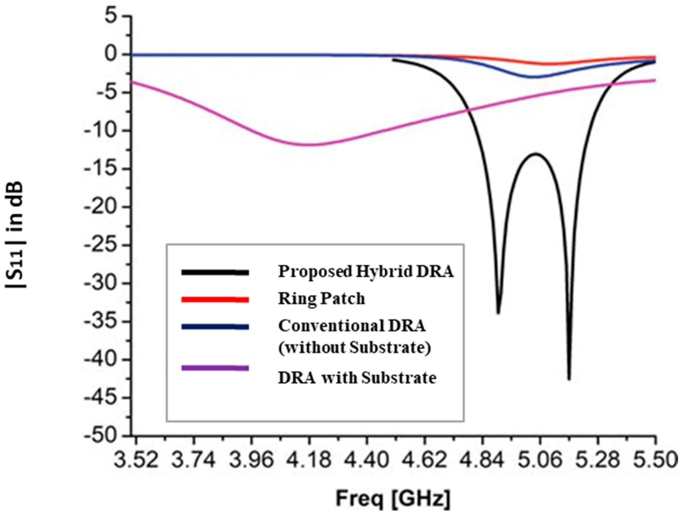
2.2. Composition and Field Analysis of the Proposed HDRA

The proposed design and composition of the hybrid DRA is illustrated in Figure 2a–d. Initially, a conventional probe-fed DRA is created for a frequency of 4 GHz, based on the fundamental resonance Equation (1) referenced in [32]. This design is chosen to transform the traditional cylindrical DRA into a hybrid model that incorporates a probe-feed mechanism, aiming to achieve resonances at 5 GHz, circularly polarized (CP) radiation, and improved gain. A substrate is then introduced between the ground and the DRA to support the ring patch. An independent resonance study of the conventional DRA, the substrate-integrated DRA, the ring patch, and the proposed DRA is carried out to analyze orthogonal mode generation and the variation of S11, as depicted in Figure 3. The fundamental resonance of the conventional probe-fed cylindrical DRA is observed at 3.9 GHz, while the resonance for the substrate-integrated DRA is shifted to 4.15 GHz. The ring patch resonates at 4.9 GHz with a lower return loss of −3 dB. The combination of the ring patch and the cylindrical element, both utilizing a common probe feed, resonates at 5 GHz, producing two orthogonal modes that result in CP radiation. This study reveals a lower resonance due to the high dielectric constant of the dielectric resonator element and a higher resonance attributed to the ring patch on a lower dielectric substrate.
The impact of ring patch and cylindrical DR elements with common coax feed creates the asymmetry that helps to generate two orthogonal modes with approximate equal magnitudes and a 90° phase-shift between them, that is, HEMxδ11 (YZ Plane) and HEMy1δ1 (XZ Plane) desired for CP radiation. With this asymmetric nature of feed arrangement, the DR is excited to operate in the HEM11δ mode (Ref. Equations (1)–(3)) with a fundamental resonant frequency of 4.9 GHz.
f r ,   H E 11 δ = 6.321 c 2 π d r , e f f + 2 0.27 + 0.36 d 2 H e f f + 0.02 d 2 H e f f 2
If a multi-segmented antenna is considered, the resonance frequency will be affected by the layers of the substrate (HS) and dielectric (HD) materials. Accordingly, the effective height (Heff), and permittivity (∈r,eff) [33,34] of the hybrid CDRA are calculated by Equations (2) and (3).
H e f f = H D R + H S u b
Similarly, the effective relative permittivity ∈r,eff in Equation (3) is given by,
r , e f f =   H e f f H D R r , C D R A + H S u b r , s u b
where “d” (D/2) is the radius of the cylindrical DR element.
The circular field rotation for the YZ and XZ planes confirms the CP radiation, as illustrated in Figure 4. It is observed that the E-Field is subverted into the DRA in the YZ plane, while in the XZ plane, it emerges from the DRA. This interaction results in two perpendicular modes at different phases, demonstrating CP radiation. To achieve the desired resonance frequency around 5 GHz, optimizing the dimensions of the probe feed length (Ph) and the height (Dh) of the dielectric resonator is crucial, as illustrated in Figure 5 and Figure 6. Specifically, an increase in the height of the coaxial pin causes the resonance frequency band to shift from higher to lower frequencies. Conversely, an increase in the DR height helps fine-tune the resonance to the targeted 5 GHz for WLAN applications.

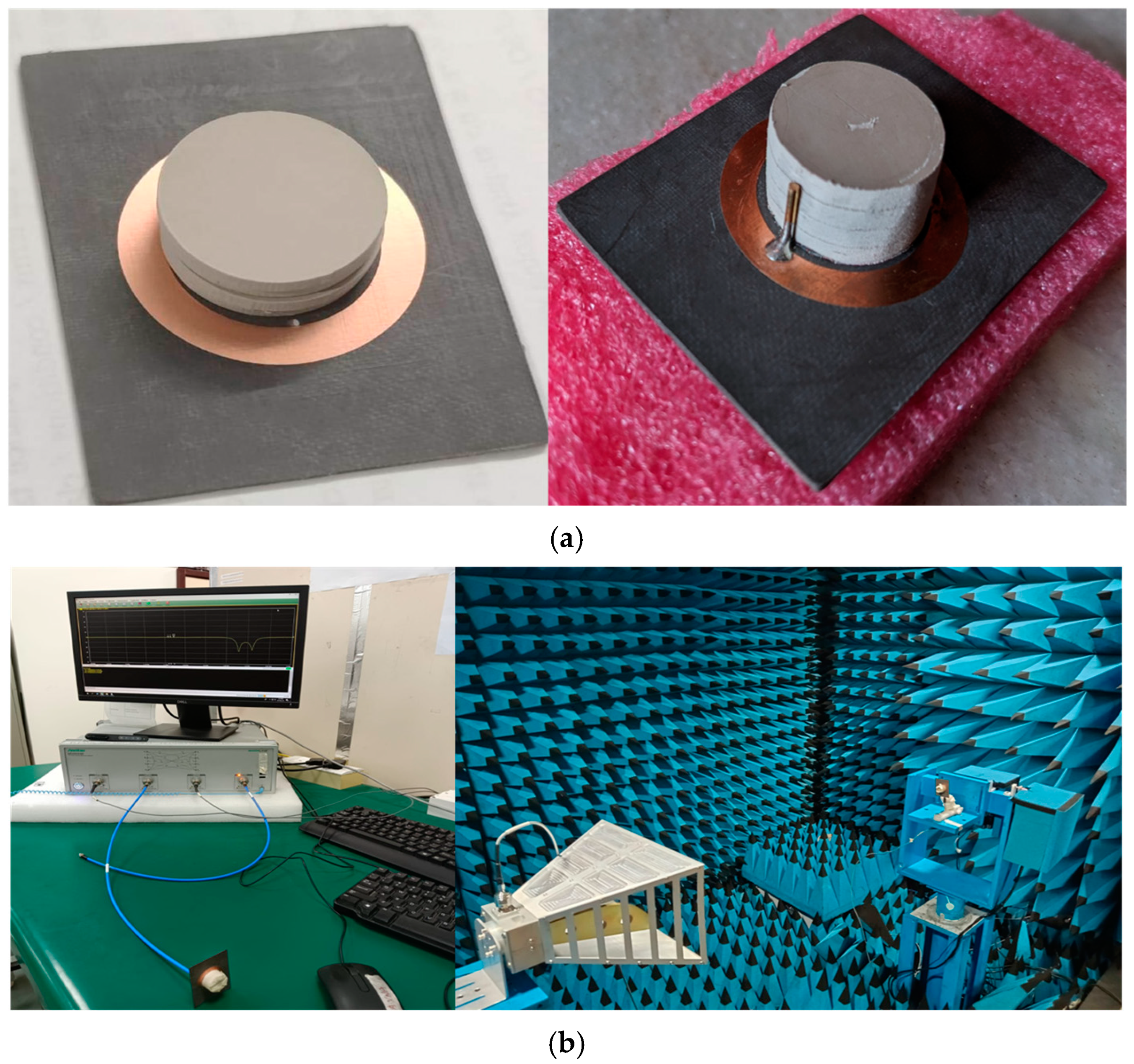
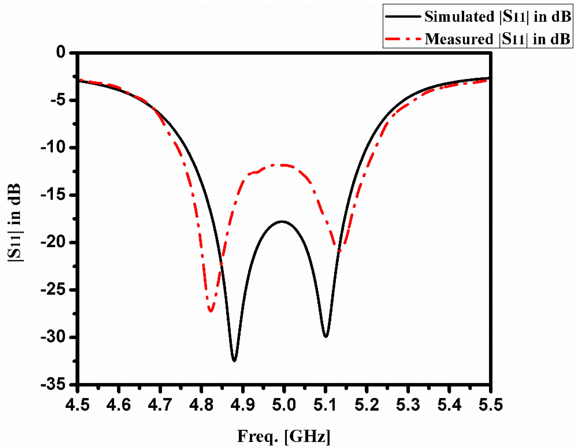
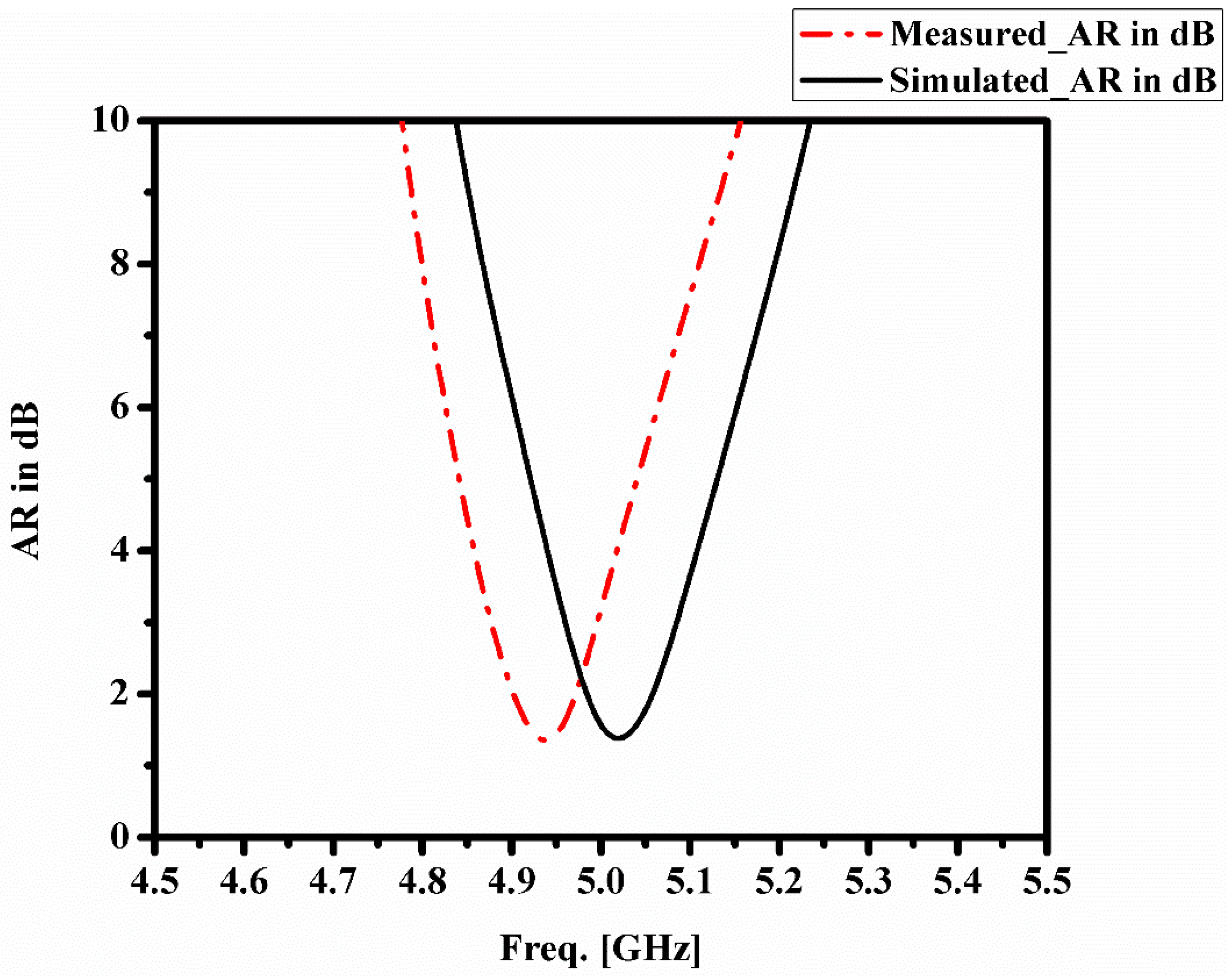
3. Prototype, Measurements, Discussion, and Assessment of Results

The prototype of the proposed HDRA is illustrated in Figure 7a, showing both the pre-bonding and post-bonding stages. The dielectric resonator element, made from Rogers 6010, is affixed to a substrate featuring a circular-ring patch composed of Rogers 5880 material. This bonding is achieved using NITTO Tape No. 5015, which also helps achieve the desired height of 10 mm for the DR element by stacking four individual layers, each 2.5 mm thick. Figure 7b presents the measurement setup for the proposed HDRA, conducted in an anechoic chamber. The far-field distance between the transmitter (Horn Antenna) and receiver (AUT), measured within the chamber is precisely 1.2 m. Antenna measurements in an anechoic chamber are conducted by mounting the antenna under test (AUT) on a positioner for precise orientation control. The chamber is calibrated using a standard gain antenna to account for system losses and ensure accuracy. Key parameters like radiation pattern, gain, polarization, and efficiency are measured using a VNA, with results processed for visualization and analysis. Figure 8 and Figure 9 display the S-parameter (S11) and axial ratio plots for the proposed antenna, respectively. The measured return loss (RL) bandwidth is 485 MHz, spanning from 4740 MHz to 5225 MHz, while the axial ratio (AR) bandwidth measures 150 MHz, ranging from 4950 MHz to 5100 MHz, with an orthogonal time-phase variation observed at 5 GHz.
The proposed antenna exhibits a gain of 7.03 dBic, as shown in Figure 10, with an optimized feed position at 90 degrees (rotated clockwise). Figure 11 presents a comparison of the XZ and YZ plane radial plots at 5 GHz, highlighting the similarities between the two patterns. The simulated and measured radiation patterns in the XZ and YZ planes are nearly identical, confirming circular polarization (CP) radiation. A summary of the simulated and measured results can be found in Table 1, and the data shows close agreement between them. The discrepancies observed between the simulated and measured results are attributed to factors such as the manual soldering of the connector to the ground, stacking, and bonding of layers with the substrate.
The data presented in Table 2 indicates that the proposed antenna aligns with existing literature regarding its performance parameters. In comparison to other studies [23,24,26,27,28,29,30,31], this research utilizes an innovative feeding mechanism that achieves a consistent gain (with a peak gain of 7.03 dBic) while providing circularly polarized (CP) radiation throughout the specified bandwidth.

4. Conclusions and Future Scope

This study presents a circularly polarized hybrid dielectric resonator antenna with an impressive return-loss (RL) bandwidth of 485 MHz (ranging from 4740 MHz to 5225 MHz) and an axial ratio (AR) bandwidth of 150 MHz (spanning from 4950 MHz to 5100 MHz). The proposed antenna achieves a peak gain of 7.03 dBic at 5 GHz, making it suitable for missile tracking, data link communications, and IEEE 802.11n WLAN applications. The paper discusses the composition of the antenna, the optimization of its feeding mechanism, and the generation of two orthogonal modes, along with relevant results. A prototype of the antenna has been fabricated, tested, and validated against simulation results. The novelty of this work lies in the combined probe feed mechanism, which integrates both the ring patch and the dielectric resonator element to produce circularly polarized radiation. However, there are limitations concerning return loss and axial ratio bandwidths. These limitations can be addressed in the future through the use of metasurfaces and optimized feed locations, which will be further explored.

Funding

This research received no external funding.

Data Availability Statement

The datasets presented in this article are not readily available due to the privacy restrictions.

Acknowledgments

We would like to express our sincere gratitude to the Principal and Management of Lendi IET (A) for providing valuable resources and support in the R & D laboratory.

Conflicts of Interest

The author declares no conflicts of interest.

References

  1. Luk, K.M.; Leung, K.W. Dielectric Resonator Antennas; Research Studies Press: Hertfordshire, UK, 2003; Volume 11. [Google Scholar]
  2. Yung, E.K.; Lee, W.W.; Luk, K.M. Microstrip antenna top-loaded by a dielectric resonator. Microw. Opt. Technol. Lett. 1994, 7, 55–57. [Google Scholar] [CrossRef]
  3. George, J.; Aanandan, C.K.; Mohanan, P.; Nair, K.G.; Sreemoolanathan, H.; Sebastian, M.T. Dielectric-resonator-loaded microstrip antenna for enhanced impedance bandwidth and efficiency. Microw. Opt. Technol. Lett. 1998, 17, 205–207. [Google Scholar] [CrossRef]
  4. Bijumon, P.V.; Menon, S.K.; Sebastian, M.T.; Mohanan, P. Enhanced bandwidth microstrip patch antennas loaded with high permittivity dielectric resonators. Microw. Opt. Technol. Lett. 2002, 35, 327–330. [Google Scholar] [CrossRef]
  5. Gupta, V.; Sinha, S.; Koul, S.K.; Bhat, B. Wideband dielectric resonator-loaded suspended microstrip patch antennas. Microw. Opt. Technol. Lett. 2003, 37, 300–302. [Google Scholar] [CrossRef]
  6. Esselle, K.P.; Bird, T.S. A hybrid-resonator antenna: Experimental results. IEEE Trans. Antennas Propag. 2005, 53, 870–871. [Google Scholar] [CrossRef]
  7. Fray, A.F. Dielectric Resonator Antenna with Wide Bandwidth. U.S. Patent 5,453,754, 26 September 1995. [Google Scholar]
  8. Ittipiboon, A.; Petosa, A.; Thirakoune, S. Bandwidth enhancement of a monopole using dielectric resonator antenna loading. In Proceedings of the 2002 9th International Symposium on Antenna Technology and Applied Electromagnetics, St. Hubert, QC, Canada, 31 July–2 August 2002; pp. 1–4. [Google Scholar]
  9. Lapierre, M.; Antar, Y.M.; Ittipiboon, A.; Petosa, A. A wideband monopole antenna using dielectric resonator loading. In Proceedings of the IEEE Antennas and Propagation Society International Symposium. Digest. Held in Conjunction with: USNC/CNC/URSI North American Radio Science Meeting (Cat. No. 03CH37450), Columbus, OH, USA, 22–27 June 2003; Volume 3, pp. 16–19. [Google Scholar]
  10. Lapierre, M.; Antar, Y.M.; Ittipiboon, A.; Petosa, A.A. Ultra-wideband monopole/dielectric resonator antenna. IEEE Microw. Wirel. Compon. Lett. 2005, 15, 7–9. [Google Scholar] [CrossRef]
  11. Guha, D.; Antar, Y.M.M.; Ittipiboon, A.; Petosa, A.; Lee, D. Improved design guidelines for the ultra-wideband monopole-dielectric resonator antenna. IEEE Antennas Wirel. Propag. Lett. 2006, 5, 373–376. [Google Scholar] [CrossRef]
  12. Yang, N.; Leung, K.W. Compact Cylindrical Pattern-Diversity Dielectric Resonator Antenna. IEEE Antennas Wirel. Propag. Lett. 2019, 19, 19–23. [Google Scholar] [CrossRef]
  13. Nalanagula, R.; Darimireddy, N.K.; Kumari, R.; Park, C.-W.; Reddy, R.R. Circularly Polarized Hybrid Dielectric Resonator Antennas: A Brief Review and Perspective Analysis. Sensors 2021, 21, 4100. [Google Scholar] [CrossRef] [PubMed]
  14. Sujatha, M.; Reddy, R.R.; Darimireddy, N.K. Circularly Polarized Compact Wideband Slotted Cylindrical Dielectric Resonator Antennas. In Proceedings of the IEEE International Conference on Antennas Innovation & Modern Techno. For Ground, Aircraft and Satellite Applications, Bangalore, India, 24–26 November 2017; pp. 1–5. [Google Scholar]
  15. Kumar, R.; Chaudhary, R.K. Circularly Polarized Rectangular DRA Coupled Through Orthogonal Slot Excited with Microstrip Circular Ring Feeding Structure for Wi-MAX Applications. Int. J. RF Microw. Comput. Aided Eng. 2018, 28, e21153. [Google Scholar] [CrossRef]
  16. Darimireddy, N.K.; Park, C.W. Electromagnetic Coupled Circularly Polarized Hybrid Antenna for LTE Applications. In Proceedings of the 2020 IEEE International Symposium on Antennas and Propagation and North American Radio Science Meeting, Montreal, QC, Canada, 5–10 July 2020; pp. 401–402. [Google Scholar] [CrossRef]
  17. Antar, Y.M.M.; Guha, D. Composite and Hybrid Dielectric Resonator Antennas: Recent Advances and Challenges. In Proceedings of the 23 National Radio Science Conference (NRSC’2006), Menouf, Egypt, 14–16 March 2006; pp. 1–7. [Google Scholar]
  18. Stout, S.M. Compact Dielectric-Loaded Patch Antennas for L-Band Mobile Satellite Applications. Master’s Thesis, Carleton University, Ottawa, ON, Canada, September 1999. [Google Scholar]
  19. Currie, C.J.; Antar, Y.M.; Petosa, A.; Ittipiboon, A. Compact Circularly Polarized Antenna Designs using Dielectrics. In Proceedings of the URSI Conference, Victoria, BC, Canada, 13–17 May 2001; pp. 359–361. [Google Scholar]
  20. Currie, C.J.; Antar, Y.M.M.; Petosa, A.; Ittipiboon, A. Compact Dielectric Loaded Circularly Polarized Microstrip Antenna. Electron. Lett. 2001, 37, 1104–1105. [Google Scholar] [CrossRef]
  21. Hsiao, F.-R.; Chiou, T.-W.; Wong, K.-L. Circularly Polarized Low-Profile Square Dielectric Resonator Antenna with a Loading Patch. Microw. Opt. Technol. Lett. 2001, 31, 157–159. [Google Scholar] [CrossRef]
  22. Perron, A.; Denidni, T.A.; Sebak, A.R. Circularly Polarized Microstrip/Elliptical Dielectric Ring Resonator Antenna for Millimeter-Wave Applications. IEEE Antennas Wirel. Propag. Lett. 2010, 9, 783–786. [Google Scholar] [CrossRef]
  23. Zhao, G.; Zhou, Y.; Wang, J.R.; Tong, M.S. A Circularly Polarized Dielectric Resonator Antenna Based on Quasi-Self-Complementary Metasurface. IEEE Transa. Antennas. Propag. 2022, 70, 7147–7151. [Google Scholar] [CrossRef]
  24. Kiyani, A.; Nasimuddin, N.; Hashmi, R.M.; Baba, A.A.; Abbas, S.M.; Esselle, K.P.; Mahmoud, A. A Single-Feed Wideband Circularly Polarized Dielectric Resonator Antenna Using Hybrid Technique with a Thin Metasurface. IEEE Access 2022, 10, 90244–90253. [Google Scholar] [CrossRef]
  25. Rajasekhar, N.; Kumari, R.; Darimireddy, N.K.; Chehri, A. A Hybrid Dielectric Resonator Antenna with Dual Sense Circular Polarization for Wireless LAN Applications. In Human Centred Intelligent Systems: Proceedings of KES-HCIS 2022 Conference; Springer Nature: Singapore, 2022; pp. 171–178. [Google Scholar]
  26. Massie, G.; Caillet, M.; Clenet, M.; Antar, Y.M.M. A New Wideband Circularly Polarized Hybrid Dielectric Resonator Antenna. IEEE Antennas Wirel. Propag. Lett. 2010, 9, 347–350. [Google Scholar] [CrossRef]
  27. Massie, G.; Caillet, M.; Clenet, M.; Antar, Y.M.M. Wideband Circularly Polarized Hybrid Dielectric Resonator Antenna. U.S. Patent 8,928,544, 6 January 2015. [Google Scholar]
  28. Zou, M.; Pan, J. Wideband Hybrid Circularly Polarized Rectangular Dielectric Resonator Antenna Excited by Modified Cross-Slot. Electron. Lett. 2014, 50, 1123–1125. [Google Scholar] [CrossRef]
  29. Lu, L.; Jiao, Y.-C.; Zhang, H.; Wang, R.; Li, T. Wideband Circularly Polarized Antenna with Stair-Shaped Dielectric Resonator and Open-Ended Slot Ground. IEEE Antennas Wirel. Propag. Lett. 2016, 15, 1755–1758. [Google Scholar] [CrossRef]
  30. Chowdhury, R.; Mishra, N.; Sani, M.M.; Chaudhary, R.K. Analysis of a Wideband Circularly Polarized Cylindrical Dielectric Resonator Antenna with Broadside Radiation Coupled with Simple Microstrip Feeding. IEEE Access 2017, 5, 19478–19485. [Google Scholar] [CrossRef]
  31. Iqbal, J.; Illahi, U.; Sulaiman, M.I.; Alam, M.M.; Su’ud, M.M.; Yasin, M.N.M. Mutual Coupling Reduction using Hybrid Technique in Wideband Circularly Polarized MIMO Antenna for WiMAX Applications. IEEE Access 2019, 7, 40951–40958. [Google Scholar] [CrossRef]
  32. Petosa, A. Dielectric Resonator Antenna Handbook; Artech House: Norwood, MA, USA, 2007. [Google Scholar]
  33. Gangwar, R.K.; Sharma, A.; Gupta, M.; Chaudhary, S. Hybrid Cylindrical Dielectric Resonator Antenna with HE11δ and HE12δ Mode Excitation for Wireless Applications. Int. J. RF Microw. Comput. Aided Eng. 2016, 26, 812–818. [Google Scholar] [CrossRef]
  34. Kajfez, D.; Glisson, A.; James, J. Computed Modal Field Distributions of Isolated Dielectric Resonators. IEEE Trans. Microw. Theory Tech. 1984, 32, 1609–1616. [Google Scholar] [CrossRef]
Figure 1. Proposed HDRA Configuration with dimensions (Ls = 60, Ws = 45, h = 0.787, Ph = 8.4, DR = 10, Dh = 10.16). All the dimensions are in “mm”.
Telecom 06 00008 g001
Figure 2. Evolution of the proposed antenna (a) Conventional DRA (without substrate) (b) DRA (with substrate) (c) Probe-fed ring patch and (d) Proposed hybrid DRA with probe at 0 deg.
Telecom 06 00008 g002
Figure 3. S11 Comparisons of all the composition stages to generate CP radiation.
Telecom 06 00008 g003
Figure 4. E- Field analysis inside the cylindrical DRA at 4.9 GHz to confirm the two orthogonal modes (a) HEMxδ11 (YZ Plane) and (b) HEMy1δ1 (XZ Plane).
Telecom 06 00008 g004
Figure 5. S11-Plots of various lengths (Ph) of the feed.
Telecom 06 00008 g005
Figure 6. S11-Plots of various heights (Dh) of the DR.
Telecom 06 00008 g006
Figure 7. (a) Fabricated HDRA prototype and (b) its measurement in an anechoic chamber.
Telecom 06 00008 g007
Figure 8. Simulated and measured S11 plots of proposed HDRA.
Telecom 06 00008 g008
Figure 9. Measured and simulated AR plots of proposed HDRA.
Telecom 06 00008 g009
Figure 10. Measured and simulated gain plots of proposed HDRA.
Telecom 06 00008 g010
Figure 11. Comparison of simulated and measured radiation pattern plots at 5 GHz (a) XZ planes (b) YZ planes.
Telecom 06 00008 g011
Table 1. Comparison table of simulation and measured results.
ParameterSimulated ResultsMeasured Results
Operating frequency band4760–5200 MHz4740–5225 MHz
RL-Bandwidth485 MHz440 MHz
AR-Bandwidth150 MHz150 MHz
Gain7.03 dBic6.9 dBic
Table 2. Performance comparison of proposed antenna with the existing literature.
[Ref.]Feeding MechanismCP Is Achieved byVolume of the HDRA (in Terms of λ at fr)
(L × W × Heff)
fr (or) CP Bands of Resonance (GHz)Gain (dBic)
[23]Penetrated coax feedQuasi-self-complementary characteristic of the metasurface6.08 λ × 4 λ × 0.06 λ24.65–26.066.03
[24]Perturbed probe feedDue to plus shaped unit-cells based metasurface and rectangular DR0.93 λ × 1.29 λ × 0.16 λ3.6–6.66–7.2
[26]Aperture coupledHaving a feeding network composed of four microstrip lines, where the four slots are geometrically arranged to ensure circular polarization0.8 λ × 0.8 λ × 0.12 λ1.08–1.825
[27]Aperture coupledDue to the arc-shaped slots0.8 λ × 0.8 λ × 0.118 λ1.22–1.713
[28]Aperture coupledModified cross-slot0.43 λ × 0.43 λ × 0.29 λ2.19–2.925
[29]An offset aperture coupled feedCombination of Stair-shaped DR and open-ended slot on the ground plane with an offset feed0.46 λ × 0.46 λ × 0.07 λ3.844–8.1463.9
[30]Dual orthogonal microstrip lineDual vertical microstrip lines with L-shaped microstrip-line arranged perpendicularly to excite orthogonal modes0.59 λ × 0.59 λ × 0.26 λ2.82–3.835.5
[31]Combination of probe feed and conformal E-shaped patchParasitic patch positioned at an optimized distance next to the conformal metal-strip of two identical rectangular DRAs is utilized to generate circular polarization0.46 λ × 0.46 λ × 0.34 λ3.50–4.956.2
Proposed WorkSingle point probe feedCombined asymmetric nature of circular ring patch and cylindrical DR elementλ × 0.75 λ × 0.18 λ4.740–5.2257.03
Disclaimer/Publisher’s Note: The statements, opinions and data contained in all publications are solely those of the individual author(s) and contributor(s) and not of MDPI and/or the editor(s). MDPI and/or the editor(s) disclaim responsibility for any injury to people or property resulting from any ideas, methods, instructions or products referred to in the content.

