Article

An Analytical Solution for Energy Harvesting Using a High-Order Shear Deformation Model in Functionally Graded Beams Subjected to Concentrated Moving Loads

1
Faculty of Civil Engineering, University of Transport and Communications, Hanoi 100000, Vietnam
2
Campus in Ho Chi Minh City, University of Transport and Communications, Ho Chi Minh City 700000, Vietnam
*
Author to whom correspondence should be addressed.
Modelling 2025, 6(3), 55; https://doi.org/10.3390/modelling6030055
Submission received: 21 May 2025 / Revised: 17 June 2025 / Accepted: 18 June 2025 / Published: 25 June 2025

Abstract

This study presents a high-order shear deformation theory (HSDT)-based model for evaluating the energy harvesting performance of functionally graded material (FGM) beams integrated with a piezoelectric layer and subjected to a moving concentrated load at constant velocity. The governing equations are derived using Hamilton’s principle, and the dynamic response is obtained through the State Function Method with trigonometric mode shapes. The output voltage and harvested power are calculated based on piezoelectric constitutive relations. A comparative analysis with homogeneous isotropic beams demonstrates that HSDT yields more accurate predictions than the Classical Beam Theory (CBT), especially for thick beams; for instance, at a span-to-thickness ratio of h/L = 12.5, HSDT predicts increases of approximately 6%, 7%, and 12% in displacement, voltage, and harvested power, respectively, compared to CBT. Parametric studies further reveal that increasing the load velocity significantly enhances the strain rate in the piezoelectric layer, resulting in higher voltage and power output, with the latter exhibiting quadratic growth. Moreover, increasing the material gradation index n reduces the beam’s effective stiffness, which amplifies vibration amplitudes and improves energy conversion efficiency. These findings underscore the importance of incorporating shear deformation and material gradation effects in the design and optimization of piezoelectric energy harvesting systems using FGM beams subjected to dynamic loading.

1. Introduction

Functionally graded materials (FGMs) are advanced composite materials characterized by a continuous variation in composition and microstructure across one or more spatial directions, optimizing their mechanical, thermal, and electromagnetic properties. Unlike traditional laminated composites, FGMs mitigate issues such as delamination and residual stresses, making them highly suitable for applications in aerospace, precision mechanics, and energy technologies [1,2].
The study of FGM beam vibrations is critical for ensuring structural integrity and operational performance in dynamically loaded environments. Various analytical and numerical methods have been employed to investigate the free vibration characteristics of FGM beams, with the finite element method (FEM) being widely used to determine natural frequencies and assess the influence of material gradation on vibrational response [1]. Additionally, the effect of elastic foundations, particularly Winkler–Pasternak foundations, significantly influences the vibrational characteristics of FGM beams [2,3,4,5]. Beyond elastic support conditions, structural imperfections such as surface cracks have been extensively examined. Aydin [6] analyzed the free vibration behavior of cracked FGM beams, while Banerjee and Ananthapuvirajah [7] employed the dynamic stiffness method to study complex beam frameworks, revealing that crack location and depth significantly impact natural frequencies. L.T. Ha et al. [8] investigated the natural frequencies of functionally graded porous nano beams using the finite element method.
Recent advancements in FGM beam vibration analysis have emphasized refined theoretical models to enhance predictive accuracy. Belarbi et al. [9] explored the vibrational characteristics of sandwich FGM beams while incorporating material uncertainties and parametric analyses. Higher-order theories, such as enhanced Timoshenko beam models [10], have been developed to improve shear deformation predictions. Furthermore, hybrid analytical–numerical techniques have been introduced to study the impact of edge cracks on FGM beam vibrations [11]. These contributions deepen the understanding of FGM beam behavior, guiding the optimization of structural designs.
Energy harvesting from structural vibrations has gained significant attention, particularly for developing self-powered sensors and electronic devices. This technology aims to reduce dependence on batteries by harnessing mechanical energy from ambient vibrations such as traffic-induced motion and industrial activities [12,13]. Among various methods, piezoelectric energy harvesting has emerged as a promising solution, utilizing piezoelectric materials to convert mechanical vibrations into electrical energy [14,15]. This approach has been widely applied in structural health monitoring and wireless sensing systems [16,17].
Recent studies have explored innovative configurations and conditions to enhance the efficiency of piezoelectric energy harvesters (PEHs). Du et al. [18] examined PEHs based on the “acoustic black hole” effect under stochastic excitation, while Zhang et al. [19] proposed bi-stable piezomagnetoelastic structures for harvesting bridge vibrations. Hassan et al. [20] demonstrated acoustic energy harvesting from railway and highway noise using piezoelectric cantilever plates. Additionally, Adoukatl et al. [21] analyzed nonlinear piezoelectric beams with piezo patches under parametric and direct excitations. Further optimizations have been achieved using semi-analytical models of two-span beams to enhance energy capture efficiency [22,23], and novel designs, such as hollow-structured piezoelectric cantilever beams, have been proposed to improve weight and sensitivity [24]. In addition, those by Amini et al. [25] , Paknejad et al. [26], and Erturk [27] focused on moving loads and surface strain fluctuations, highlighting the applicability of PEHs in civil infrastructure. Collectively, these studies not only strengthen the theoretical foundation of piezoelectric energy harvesting but also open new avenues for efficient energy capture from vibrations in real-world environments.
The application of FGMs in energy harvesting has garnered increasing interest due to their ability to withstand varying stress and strain conditions while improving energy conversion efficiency. Studies have demonstrated the superior performance of FGM beams in complex vibrational environments, making them ideal for self-powered systems requiring long-term operation [28,29]. Higher-order shear deformation theory (HSDT) plays a crucial role in accurately modeling FGM beams for energy harvesting, as it accounts for significant shear deformation effects that impact small-scale energy harvesters [12,30]. By incorporating HSDT, researchers have optimized energy harvesting systems, improving efficiency in dynamic conditions [31,32].
The integration of artificial intelligence (AI) techniques has further enhanced the performance of piezoelectric harvesters. Bendine et al. [33] utilized neural networks and optimization algorithms to improve the efficiency of non-uniform FGM piezoelectric beams under nonlinear conditions. Dehkordi and Beni [30] explored size-dependent electromechanical effects to enhance energy conversion, demonstrating the potential of AI-driven methodologies in optimizing piezoelectric energy harvesters.
Nonlinear dynamics in energy harvesting systems have also been a key research focus. Keshmiri et al. [15] designed a nonlinearly tapered FGM piezoelectric energy harvester to improve efficiency, while Fatehi and Fari [12] investigated the impact of nonlinear vibration patterns on energy harvesting effectiveness. The influence of moving loads on piezoelectric harvesters has been extensively studied, with Khiem et al. [29] analyzing cracked FGM beams under moving loads and Mousavi et al. [34] examining energy harvesting from bridge vibrations induced by vehicle motion. Recent developments have introduced innovative energy conversion optimization techniques. Ray and Jha [31] derived exact solutions for bimorph piezoelectric harvesters, and Song et al. [32] proposed a width-splitting method to enhance energy harvesting efficiency in coupled bending–torsion vibrations.
The primary objective of this study is to develop a rigorous HSDT-based model for the dynamic analysis and energy harvesting assessment of FGM beams integrated with a surface-bonded piezoelectric layer subjected to a moving concentrated load at constant velocity. The governing equations of motion are systematically derived from Hamilton’s principle, incorporating higher-order shear deformation effects to accurately capture the realistic kinematics of the beam. The dynamic response is subsequently obtained using the State Function Method, employing trigonometric functions to precisely represent the mode shapes. A detailed comparative analysis with homogeneous isotropic beams based on CBT is conducted to demonstrate the superior accuracy of the HSDT model, particularly for beams with moderate to large span-to-thickness ratios. Based on the computed dynamic response, the induced electric potential and harvested power are evaluated through established piezoelectric constitutive relations. The parametric influence of load velocity and material gradation index on vibration characteristics and electromechanical energy conversion efficiency is further investigated. The findings highlight the critical importance of incorporating shear deformation and material gradation effects in the predictive modeling and optimal design of piezoelectric energy harvesting systems utilizing FGM beams under dynamic loading conditions, thereby providing a robust theoretical framework for advancing practical applications in structural energy harvesting.
In contrast to conventional studies that primarily focus on harmonic or static excitations, this study addresses the dynamic interaction between a moving concentrated load and a functionally graded beam integrated with a surface-bonded piezoelectric layer. The originality of the present work lies in the development of a high-order shear deformation theory (HSDT)-based analytical model that captures both the non-uniform shear deformation across the thickness and the spatial-temporal effects induced by the moving load. Furthermore, the application of the State Function Method enables a closed-form solution for the dynamic response, which is subsequently used to quantify the output voltage and harvested power through piezoelectric coupling. By incorporating both shear deformation effects and material gradation, the proposed model provides enhanced accuracy in predicting electromechanical performance, particularly for moderately thick FGM beams—an aspect that is often overlooked in classical formulations.

2. Formulation for a Beam

Consider the FGM beam shown in Figure 1, with a rectangular cross-section having a width b and a cross-sectional height h. The beam has a length L, and the coordinate axes are defined as follows: the x-axis along the length of the beam, the y-axis along the width of the cross-section, and the z-axis along the height of the cross-section. The FGM beam is subjected to a constant moving load P0 traveling at a constant velocity v. A thin piezoelectric layer is bonded at the mid-span region, and the stiffness of this piezoelectric layer is neglected in the dynamic response analysis of the beam. The notations employed in this study, along with their corresponding definitions and units, are provided in Appendix A.

2.1. Basic Equations FGM Beam

To enhance the predictive accuracy of the Classical Plate Theory (CPT), particularly in capturing transverse shear deformation, a refinement of the displacement field is introduced by incorporating an additional term. Consequently, the transverse displacement W is represented by the combination of bending-induced w b and shear-induced components w s as described in [35,36,37], each being functions of the in-plane coordinates x, y, and time t:
W x , y , z , t = w b x , t + w s x , t
The longitudinal displacement U along the x-axis is decomposed into two distinct parts: one arising from bending deformation u b and the other from shear deformation u s .
u b = z w b x
u s = z 1 5 + 8 5 π cos π z h w s x
According to Kirchhoff’s hypothesis applied to slender beams, cross-sections that are initially perpendicular to the neutral axis remain plane and perpendicular after deformation [38]. This assumption effectively neglects transverse shear deformation, which is a fundamental premise of the Classical Beam Theory (CBT). In this context, Equation (2) describes a displacement field consistent with Kirchhoff’s assumption, where axial displacement is uniform along the beam thickness and transverse shear strains are assumed to be zero.
As a result, the displacement field is reformulated in the following manner:
U x , z , t = u x , t z w b x + z 1 5 + 8 5 π cos π z h w s x
W x , z , t = w b x , t + w s x , t
In Equations (4) and (5), U and W represent the axial displacement along the x-axis and the transverse displacement along the z-axis, respectively, at an arbitrary point in the beam. The displacement components u, wb and ws denote, respectively, the axial displacement, the transverse displacement due to bending, and the transverse displacement due to shear at the neutral axis of the FGM beam. The linear strain components are determined through the partial derivatives of the displacement components, as expressed in Equations (6) and (7).
ε x = U x = u x z 2 w b x 2 + f ^ 2 w s x 2 = ε 0 x + z κ x b + f ^ κ x s
γ x z = U z + W x = ( 1 d f ^ d z ) w s x = g ^ w s x
where
f ^ = z 1 5 8 5 π cos π z h ,   g ^ = 4 5 + 8 5 π cos π z h 8 z 5 h sin π z h
  κ x b κ x s = 2 w b x 2 2 w s x 2
When the shear-related term ws in Equations (4) and (5) is omitted, the formulation reduces to that of the Classical Plate Theory (CPT). In the case of a functionally graded material (FGM) beam composed of two distinct constituents, such as ceramic and metal, the effective mechanical properties namely Young’s modulus E and mass density ρ are typically described as spatially varying functions, capturing the gradual transition between the two materials [39].
E z = E c E m z h + 1 2 n + E m
ρ z = ρ c ρ m z h + 1 2 n + ρ m
In this context, the index n denotes the exponent in the power-law function describing the variation in material properties, including the modulus of elasticity and mass density, through the thickness of the beam. The material gradation index n is a dimensionless parameter that defines the distribution of material phases across the thickness of a functionally graded beam. It governs the volume fraction of the ceramic and metal constituents through a power-law function. A lower value of n corresponds to a ceramic-rich configuration, whereas a higher n results in a metal-dominated profile. The material gradation index significantly affects the effective stiffness and mass distribution of the beam. The subscripts c and m refer to the ceramic and metallic phases of the FGM beam, respectively. Poisson’s ratio μ is considered uniform throughout the beam. Based on these assumptions, the linear constitutive equations for the FGM beam can be expressed as follows:
σ x τ x z = Q 11 0 0 Q 55 ε x γ x z
where
Q 11 = E z ,   Q 55 = E z 2 1 + μ

2.2. Governing Equations of Motion

Consider an FGM beam subjected to a constant-magnitude load P0, which moves along the beam with a constant velocity v. The kinetic energy of the system’s mass can be represented as:
T = 1 2 V ρ z u ˙ z w ˙ b x f ^ w ˙ s x 2 + w ˙ b + w ˙ s 2 d V
where ρ(z) is the density of the material.
For the case of a beam subjected to a constant moving load P0 traveling at a constant velocity v, the position of the load at time t is given by x(t) = vt. This load can be represented as a distributed load using the Dirac delta function δ(·):
q = P 0 δ x v t
The loading potential energy can be expressed as:
P = 0 L q w b + w s d x = 0 L P 0 δ x v t w b + w s d x
The strain energy stored in the FGM beam is expressed as:
Π = 1 2 V σ x ε x + τ x z γ x z d V
By substituting Equations (6) and (12) into Equation (17) and performing the integrations through the height of the beam, Equation (17) is reformulated as Equation (18):
Π = 1 2 0 L N ε x 0 + M b κ x b + M s κ x s + Q γ x z s d x
The beam’s internal force and bending moment resultants are characterized by the following definitions:
N = A σ x d A = A ε 0 x + B κ x b + B s κ x s
M b = A z σ x d A = B ε 0 x + D κ x b + D s κ x s
M s = A f ^ σ x d A = B s ε 0 x + D s κ x b + H s κ x s
Q = A g ^ τ x z d A = A S w s x
Here, the beam stiffness parameters, A , B , etc., are defined as follows:
A = A Q 11 d A
B = A z Q 11 d A
B S = A f ^ Q 11 d A
D = A z 2 Q 11 d A
D S = A z f ^ Q 11 d A
H S = A f ^ 2 Q 11 d A
A S = A g ^ 2 Q 55 d A
Applying Hamilton’s principle to derive the equations of motion, the integral form of this principle is expressed as follows:
t 1 t 2 δ Π + δ P δ T d t = 0
By substituting Equations (14), (16) and (18) into Equation (30) and assembling the coefficients corresponding to δ u ,   δ w b ,   and   δ w s , the equations of motion for the beam are expressed as follows:
N x = I 0 u ¨ I 1 w ¨ b x L 1 w ¨ s x
2 M b x 2 + P 0 δ x v t = I 0 w ¨ b + w ¨ s + I 1 u ¨ x I 2 2 w ¨ b x 2 L 2 2 w ¨ s x 2
2 M s x 2 + Q x + P 0 δ x v t = I 0 w ¨ b + w ¨ s + L 1 u ¨ x L 2 2 w ¨ b x 2 L ^ 1 2 w ¨ s x 2
N , Q , M b , M s represent the stress resultants. The inertia terms I i , L i , L ^ 1 are defined as follows:
I i = A ρ z z i d z , i = 0 , 1 , 2
L i = A ρ z z i 1 f ^ d z , i = 1 , 2
L ^ 1 = A ρ z f ^ 2 d z

3. Method of Solution

To determine the dynamic response of an FGM beam subjected to a constant moving load traveling at a constant velocity v, the state-space method [40] is employed in this study. The governing equations are described in Equation (31) are used to analyze the dynamic response of a simply supported FGM beam, as follows:
u = w b = w s = 0 w b x = w s x = 0 N = 0 M b = M s = 0   at   x = 0 , L  
The axial displacement, transverse displacement due to bending, and transverse displacement due to shear at the mid-plane of the beam are assumed in the form of sinusoidal functions that satisfy the boundary conditions at both ends of the beam:
u x , t = n = 1 U n t cos α x
w b x , t = n = 1 W b n t sin α x
w s x , t = n = 1 W s n t sin α x
with U n , W b n , W s n are the unknown maximum displacement components corresponding to axial displacement, transverse displacement due to bending, and transverse displacement due to shear, respectively.
The transverse load q is represented in the form of a Fourier series as follows:
q ( x ) = n = 1 P n sin α x
with Pn corresponds to the load amplitude evaluated from:
P n = 2 L 0 L P 0 δ x v t sin α x d x = 2 L P 0 sin α v t
where α = n π L .
By substituting Equation (38) into Equation (31) and applying the orthogonality principle of sinusoidal functions in Equation (38), Equation (31) can be reformulated as follows:
s 11 s 12 s 13 s 12 s 22 s 23 s 13 s 23 s 33 ω 2 m 11 m 12 m 13 m 21 m 22 m 23 m 13 m 23 m 33 U n W n b W n s = 0 P n P n
where
m 11 = I 0
m 12 = α I 1
m 13 = α L 1
m 22 = I 0 + α 2 I 2
m 23 = I 0 + α 2 L 2
m 33 = I 0 + α 2 L ^ 1
s 11 = A α 2
s 12 = B α 3
s 13 = B s α 3
s 22 = D α 4
s 23 = D s α 4
s 33 = α 4 H s + α 2 A s
To apply the state-space method, Equation (43) is rewritten as:
U ¨ n W ¨ n b W ¨ n s + m 11 m 12 m 13 m 21 m 22 m 23 m 13 m 23 m 33 1 s 11 s 12 s 13 s 12 s 22 s 23 s 13 s 23 s 33 U n W n b W n s = m 11 m 12 m 13 m 21 m 22 m 23 m 13 m 23 m 33 1 0 P n P n
Notation
h 11 h 12 h 13 h 12 h 22 h 23 h 13 h 23 h 33 = m 11 m 12 m 13 m 21 m 22 m 23 m 13 m 23 m 33 1 s 11 s 12 s 13 s 12 s 22 s 23 s 13 s 23 s 33
f ^ 1 f ^ 2 f ^ 3 = m 11 m 12 m 13 m 21 m 22 m 23 m 13 m 23 m 33 1 0 P n P n
Subsequently, Equation (56) is reformulated as follows:
U ˙ n W ˙ n b W ˙ n s U ¨ n W ¨ n b W ¨ n s = 0 0 0 1 0 0 0 0 0 0 1 0 0 0 0 0 0 1 h 11 h 12 h 13 0 0 0 h 12 h 22 h 23 0 0 0 h 13 h 23 h 33 0 0 0 U n W n b W n s U ˙ n W ˙ n b W ˙ n s + 0 0 0 f ^ 1 f ^ 2 f ^ 3 or Z ˙ = A Z + b
where
A = 0 0 0 1 0 0 0 0 0 0 1 0 0 0 0 0 0 1 h 11 h 12 h 13 0 0 0 h 12 h 22 h 23 0 0 0 h 13 h 23 h 33 0 0 0
Z = U n W n b W n s U ˙ n W ˙ n b W ˙ n s
b = 0 0 0 f ^ 1 f ^ 2 f ^ 3
Solving Equation (59) by state space method we can obtain solution as follows:
Z t = L e λ 1 t τ 0 0 0 0 0 0 e λ 2 t τ 0 0 0 0 0 0 e λ 3 t τ 0 0 0 0 0 0 e λ 4 t τ 0 0 0 0 0 0 e λ 5 t τ 0 0 0 0 0 0 e λ 6 t τ L 1 U n 0 W n b 0 W n s 0 U ˙ n 0 W ˙ n b 0 W ˙ n s 0 + 0 t L e λ 1 t τ 0 0 0 0 0 0 e λ 2 t τ 0 0 0 0 0 0 e λ 3 t τ 0 0 0 0 0 0 e λ 4 t τ 0 0 0 0 0 0 e λ 5 t τ 0 0 0 0 0 0 e λ 6 t τ L 1 0 0 0 f ^ 1 τ f ^ 2 τ f ^ 3 τ d τ
where λ i , L are eigenvalues and eigen matrix of matrix A

4. Piezoelectric Energy Harvesting

The standard form of the piezoelectric constitutive equations for piezoelectric materials is defined as form in [41]:
ε k = d j k c E j + s k m E σ m
D i = e i j σ E j + d i m d σ m
where E is the external electric vector, D is the electric displacement vector, ε is the strain and s E is the elastic compliance tensor. The piezoelectric layer is bonded to the bottom surface of the beam; therefore, it is necessary to calculate the axial strain along the x-direction:
ε x = U x = u x z 2 w b x 2 f ^ 2 w s x 2
The electric displacement is defined as the form when there is no external voltage E = 0:
D 3 = d 31 E p ε x = d 31 E p u x + h 2 2 w b x 2 f ^ h 2 2 w s x 2
The voltage obtained from the piezoelectric pad across the resistive load can be described by the equation according to Erturk and Inman [41]:
d V t d t + V t C p R = e 31 b C p L 1 L 2 t u x + h 2 2 w b x 2 f ^ h 2 2 w s x 2 d x
where Cp is the piezoceramic patch capacitance, and e31 is the piezoelectric stress constant.
C p = e 33 S b p L 2 L 1 h p
Transform formula (68) as follows:
d V t d t + V t C p R = e 31 h pc b C p L 1 L 2 3 i = 0 B i sin i π L x T i t x 2 t d x = i = 0 ψ i d T i t d t
The solution of the first-order differential equation (70) is determined as formula:
V t = e t C p R i = 0 ψ i d T i t d t e t C p R d t
The harvested power from the piezoelectric layer due to the vibration of the FGM beam is determined by the following equation:
P t = 1 R e t C p R i = 0 ψ i d T i t d t e t C p R d t 2

5. Numerical Examples

5.1. Verification Example

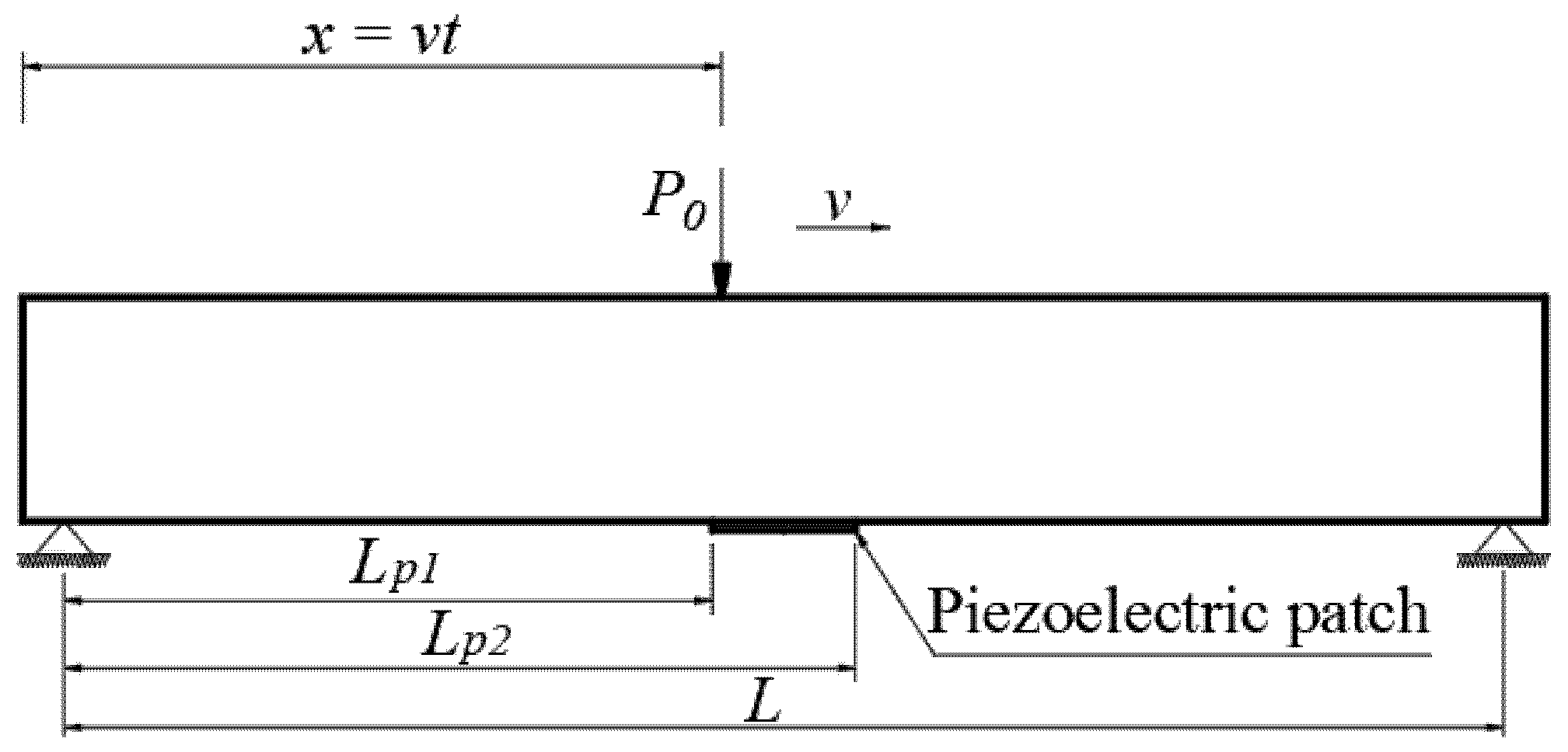
To validate the results of the energy harvesting analysis from the vibration of FGM beams based on the higher-order shear deformation theory (HSDT), the present study compares its findings with those reported by D.S. Dan [42]. In that reference, the author investigated energy harvesting from the vibration of a simply supported beam made of isotropic material subjected to a moving point load, as shown in Figure 2. The analytical solution was developed using the Classical Beam Theory to formulate the governing differential equations. This comparison serves to verify the accuracy and reliability of the proposed model in the current study.
Consider a simply supported beam with a span length of L = 10 m, an elastic modulus of E = 30 × 109 Pa, subjected to a moving concentrated load P0 >= 5 kN traveling at velocities of 10 m/s and 20 m/s. The beam has a rectangular cross-section with a width of b = 30 cm and two height configurations: Case 1 with height h = 50 cm, and Case 2 with height h = 80 cm. The respective height-to-span ratios h/L are 1/20 and 1/12.5.
The piezoelectric layer, made of zirconate titanate (PZT-5A) according to [27], is bonded to the bottom surface at the mid-span region of the beam. The material properties are listed in Table 1.
Figure 3 illustrates the mid-span displacement of the beam analyzed using CBT and HSDT corresponding to two height-to-span ratios, h/L = 1/20 and h/L = 1/12.5, under moving point loads traveling at velocities of 10 m/s and 20 m/s. Specifically, in Figure 3a,b, when the beam has a relatively small height (h/L = 1/20), the displacement predicted by HSDT is approximately 2–3% greater than that obtained from CBT at the extreme points of the displacement curves. This indicates that shear deformation has a negligible effect on slender beams. However, when the beam height increases (h/L = 1/12.5, shown in Figure 3c,d), the discrepancy between the two theories becomes more pronounced. In this case, the displacement calculated using HSDT is approximately 5–6% larger than that obtained using CBT at peak positions, highlighting the significant role of shear deformation in the dynamic response of deeper beams.
In essence, CBT assumes that cross-sections remain plane and perpendicular to the neutral axis after deformation, thereby neglecting the effect of transverse shear deformation. This assumption holds for slender beams with small height-to-span ratios. However, as the beam becomes deeper, the contribution of shear deformation becomes non-negligible due to the non-uniform distribution of shear stress across the thickness. The HSDT overcomes this limitation by allowing the transverse shear strain to vary through the thickness without requiring a shear correction factor. As a result, the predicted displacements reflect the actual flexibility of the structure more accurately, especially in dynamic problems involving moving loads. These findings emphasize the necessity of employing higher-order shear deformation theory when analyzing the vibration of beams with moderate to large height in order to achieve accurate results.
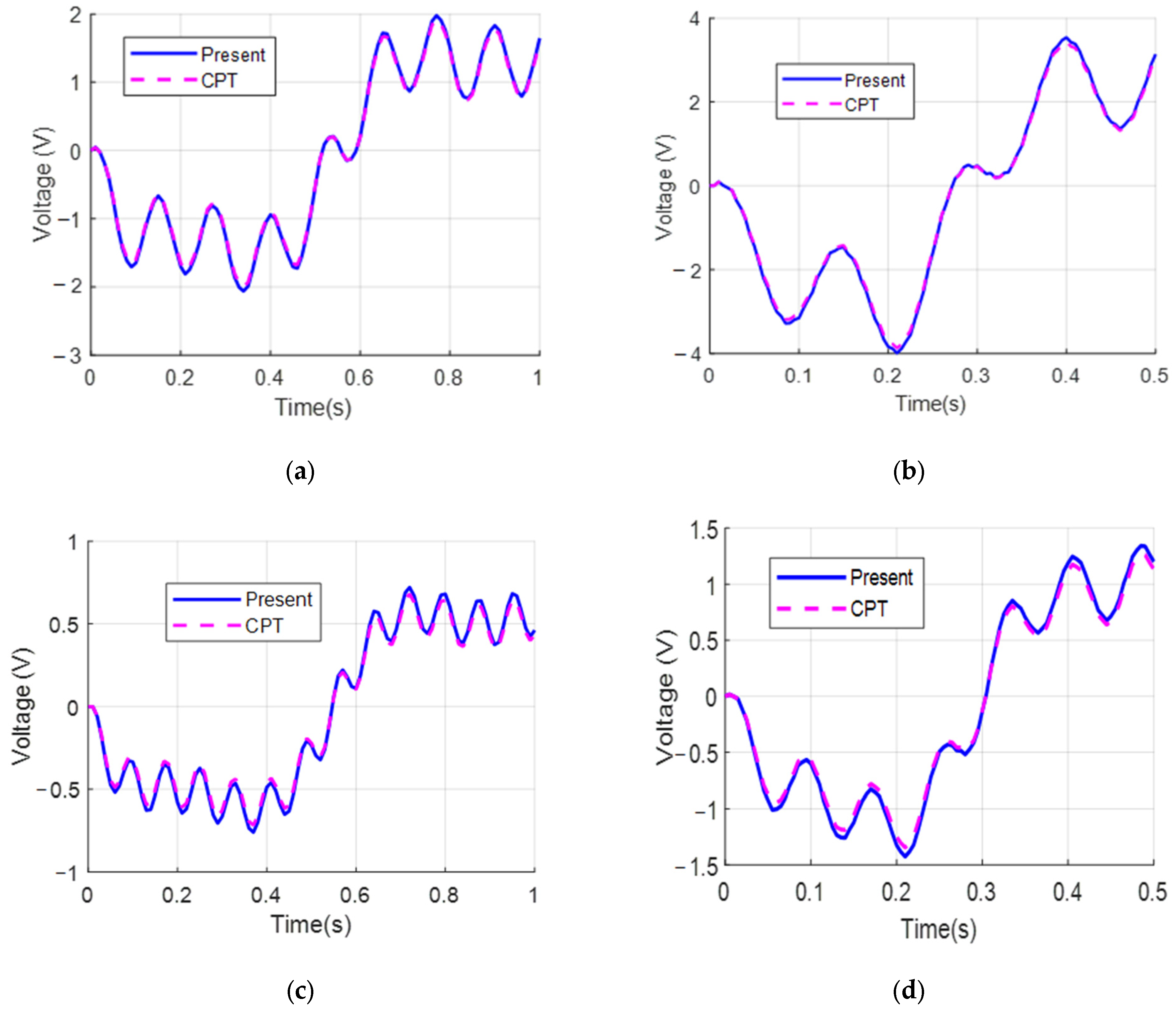
As shown in Figure 4, the analytical results reveal a significant discrepancy in the peak values of the electric potential when comparing the predictions of the two beam theories. Specifically, for the case of a beam with a small height-to-span ratio, the electric potential obtained from HSDT, which accounts for shear deformation, is approximately 2–3.5% greater than that predicted by CBT. In contrast, as the beam height increases, the influence of shear deformation becomes more pronounced: the electric potential calculated using HSDT exceeds that of CBT by approximately 5–7%. This demonstrates that shear deformation not only increases the displacement response but also has a considerable impact on the harvested electric energy in piezoelectric systems.
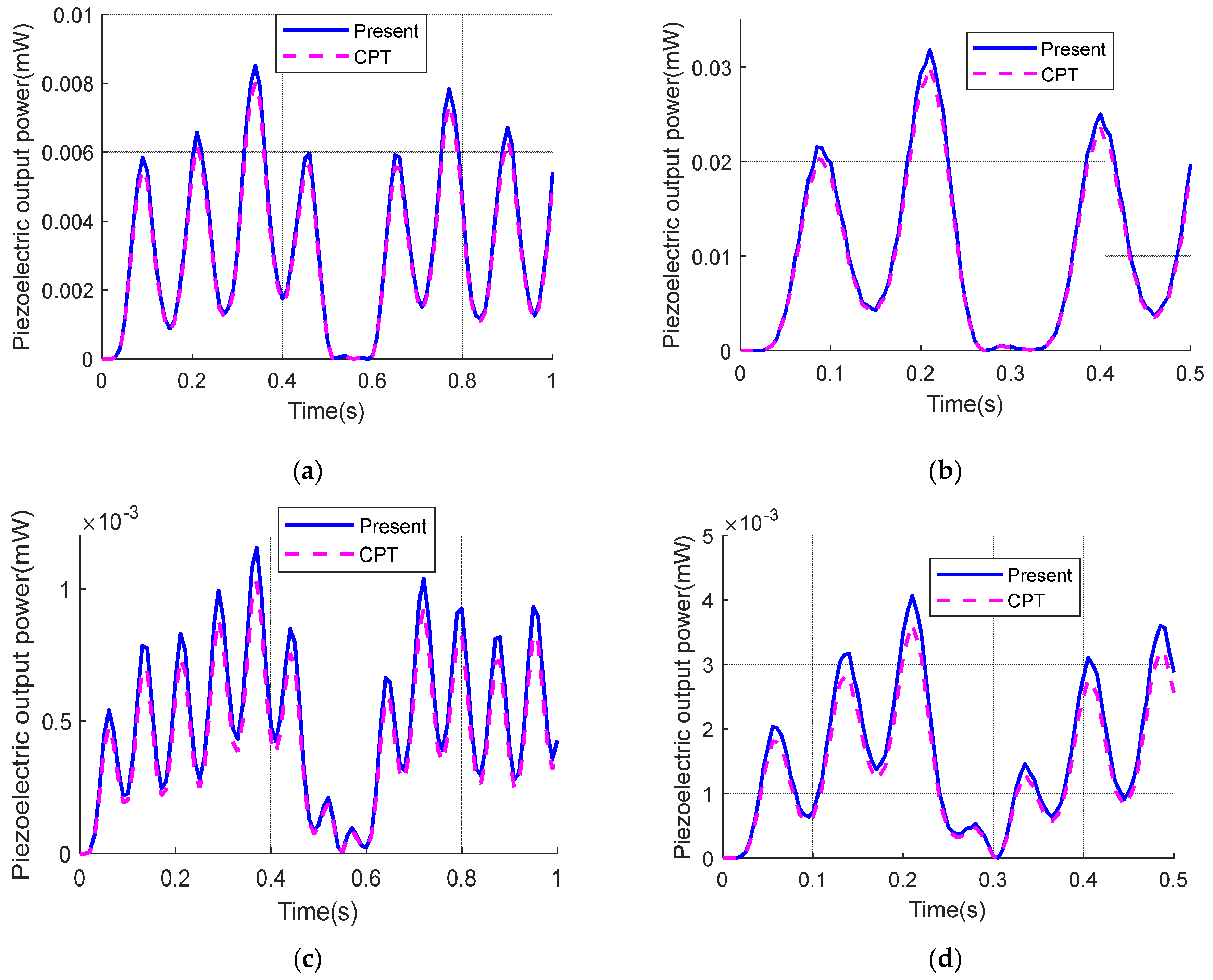
Building on these observations, Figure 5 presents a comparison of peak power output calculated using CBT and HSDT for beams with different height-to-span ratios. For beams with a relatively small height (h/L = 1/20), the power output predicted by HSDT is approximately 4–6% higher than that predicted by CBT. In contrast, for beams with larger height (h/L = 1/12.5), the influence of shear deformation on power output becomes more substantial, with HSDT results exceeding CBT by approximately 7–12%. These findings indicate that shear deformation plays a critical role in enhancing the harvested power in piezoelectric energy harvesting systems, particularly for beams with greater depth.

5.2. Investigation of Energy Harvesting from Vibrations of FGM Beams

In this section, we investigate the energy harvesting performance of a simply supported functionally graded beam with the following dimensions: length L = 2 m, width b = 0.14 m, and height h = 0.08 m. The material properties of the beam are identical to those reported in [43], where
  • Metal phase: E m = 70   GPa ,     ρ m = 2702   kg / m 3 ;
  • Ceramic phase: E c = 380   GPa ,     ρ c = 3800   kg / m 3 ;
The piezoceramic patch is rectangular, with dimensions: length lp = 0.05 m, width bp = 0.02 m, and thickness tp = 0.0002 m. The properties of the piezoelectric material are adopted as given in Section 5.1. To investigate the influence of the beam stiffness characterized by the material gradation index n in Equation (10), the harvested electrical energy from the piezoelectric layer is evaluated for three values of n, namely n = 1, 2, and 5. The analysis is conducted under moving load conditions with velocities v = 10 m/s and v = 20 m/s.
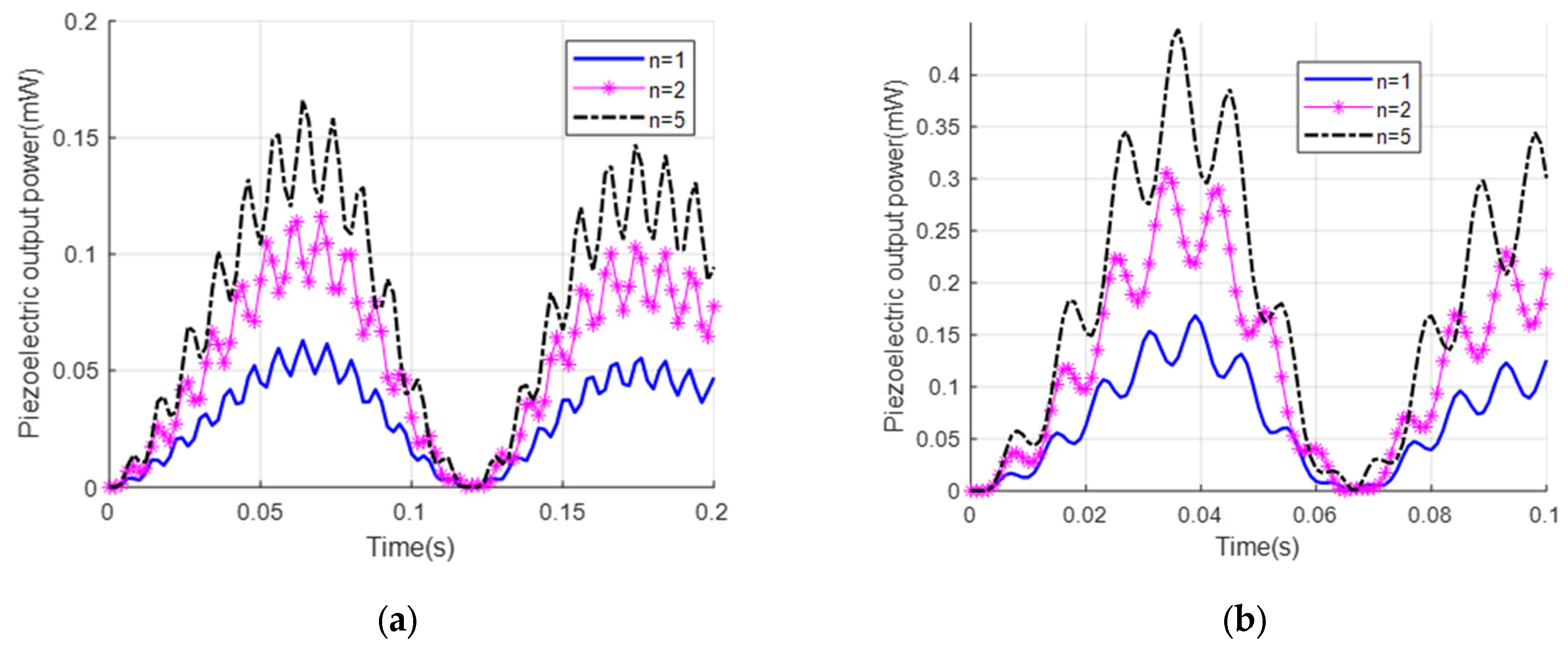
Figure 6 and Figure 7 illustrate the voltage and harvested power from the FGM beam corresponding to different values of the material gradation index n, which represents the material gradation and directly influences the effective stiffness of the beam. As the material gradation index n increases, the effective stiffness of the beam decreases, resulting in more pronounced vibrations under the action of the moving load. The increased vibration amplitude leads to a higher voltage generated in the piezoelectric layer. However, the harvested power increases significantly faster than the voltage, since power is proportional to the square of the voltage. Moreover, when the load velocity increases from 10 m/s to 20 m/s, both the voltage and harvested power rise markedly. This indicates that load velocity is also a critical factor affecting energy harvesting performance, as it alters the beam’s vibration characteristics and the excitation frequency of the piezoelectric layer.
The velocity of the moving load plays a critical role in determining the performance of piezoelectric energy harvesting systems mounted on FGM beams. As the velocity increases, the excitation frequency imparted to the beam also rises, which can significantly influence the dynamic response of the structure. The excitation frequency induced by a moving load plays a significant role in the dynamic response of the beam. It can be approximated by the expression f ex = n π v L , where v is the velocity of the moving load and L is the beam length. Resonance occurs when this excitation frequency coincides with one of the beam’s natural frequencies. In the present study, for a beam with a length of L = 2 m  and a fundamental natural frequency of approximately f1 ≈ 114.76 Hz, the corresponding resonance velocity is calculated as vr = 36.53 m/s. This result explains the significant increase in vibration amplitude and harvested electrical power when the load velocity approaches the resonance value, and emphasizes the importance of accounting for resonance effects in the design and placement of piezoelectric energy harvesting devices subjected to moving loads.
According to the direct piezoelectric effect, an increase in mechanical strain leads to a higher voltage generated across the electrodes. This behavior is clearly illustrated in Figure 8a, where the peak voltage exhibits a substantial increase as the load velocity rises from 10 m/s to 15 m/s and further to 20 m/s, especially at time instances corresponding to the maximum vibration amplitudes of the beam. Similarly, the output power is also notably enhanced with increasing velocity, as shown in Figure 8b. Specifically, the curve corresponding to v = 20 m/s reaches the highest peak power, followed by those of v = 15 m/s and v = 10 m/s. The growth trend of output power is more pronounced than that of the voltage. Moreover, higher velocities lead to increased strain rates in the piezoelectric layer, which can contribute to improving the intrinsic electromechanical conversion efficiency of the material.

6. Conclusions

This study presents a comprehensive model for analyzing the energy harvesting performance of FGM beams equipped with a piezoelectric layer bonded to the bottom surface and subjected to a moving concentrated load with constant velocity. The governing equations of motion were derived based on the principle of virtual work, incorporating HSDT. The dynamic response of the beam was obtained using the State Function Method with trigonometric functions representing the mode shapes. Based on this dynamic response, the electric potential and harvested power from the piezoelectric layer were subsequently calculated.
The results indicate that the load velocity significantly influences the energy harvesting performance; both the output voltage and harvested power increase with increasing velocity, with the power exhibiting a faster growth due to its quadratic dependence on voltage. Higher load velocities also lead to an increased strain rate in the piezoelectric layer, thereby enhancing the electromechanical energy conversion efficiency. Furthermore, the material gradation parameter n, which directly affects the effective stiffness of the FGM beam, plays a critical role. As n increases, the effective stiffness decreases, resulting in larger vibration amplitudes and higher voltage generation in the piezoelectric layer. Correspondingly, the harvested power increases more rapidly than the voltage due to the squared relationship. Compared to CBT, the HSDT-based model provides more accurate predictions of deformation and voltage output, especially for beams with greater thickness, highlighting the importance of shear deformation in the dynamic analysis and energy harvesting of FGM beams.
These findings emphasize the necessity of incorporating the HSDT model and considering both load velocity and material gradation parameter n as key design factors in the development of piezoelectric energy harvesting systems using FGM beams. This research opens new pathways for optimizing the design and practical applications of vibration-based energy harvesting in structures subjected to moving loads.
The developed analytical model provides a theoretical foundation for designing piezoelectric energy harvesting systems in dynamically loaded structures. Its applicability is particularly relevant to smart civil infrastructures, such as bridges and pavements, where moving loads from vehicles induce vibrations that can be exploited for sustainable energy generation. This approach supports the development of self-powered monitoring systems and aligns with modern trends in green energy and intelligent structural design.
In future work, the proposed model may be extended using numerical methods such as the finite element method or Ritz-based approaches to analyze more complex configurations and loading conditions. Experimental studies will also be conducted to validate the theoretical predictions presented in this work and confirm the model’s accuracy under real-world conditions. Furthermore, the model can be generalized to investigate alternative piezoelectric layer configurations, such as bonding the patch on the top surface or on both surfaces of the beam, which may lead to improved energy harvesting performance depending on design requirements and excitation conditions.

Author Contributions

Conceptualization, S.-D.D. and D.-D.N.; methodology, S.-D.D.; software, D.-D.N.; validation, S.-D.D., T.-H.N. and N.-L.N.; formal analysis, N.-L.N.; investigation, T.-H.N.; resources, N.-L.N.; data curation, S.-D.D.; writing—original draft preparation, D.-D.N.; writing—review and editing, T.-H.N.; visualization, N.-L.N.; supervision, S.-D.D.; project administration, S.-D.D. All authors have read and agreed to the published version of the manuscript.

Funding

This research is funded by the Ministry of Education and Training (MOET), Vietnam, under the grant number B2023-GHA-09.

Data Availability Statement

The data presented in this study are available in the article.

Acknowledgments

This research is funded by the Ministry of Education and Training (MOET), Vietnam, under the grant number B2023-GHA-09.

Conflicts of Interest

The authors declare no conflict of interest.

Appendix A. List of Parameters Used in the Analytical Model

SymbolDescriptionUnit
x, zLongitudinal and thickness coordinatesm
tTime variables
LBeam lengthm
bBeam widthm
hBeam thicknessm
u(x,t)Axial displacement at the neutral axism
wb(x,t)Transverse displacement due to bendingm
ws(x,t)Transverse displacement due to shearm
w(x,t)Total transverse displacement m
ρ(z)Density varying through thicknesskg/m³
ρmDensity of the metal phasekg/m³
ρcDensity of the ceramic phasekg/m³
E(z)Young’s modulus varying through thicknessPa
EmYoung’s modulus of metalPa
EcYoung’s modulus of ceramicPa
νPoisson’s ratio (assumed constant)
G(z)Shear modulus varying through thicknessPa
nMaterial gradation index
d31Piezoelectric strain constantC/N
e31Piezoelectric stress constantC/m²
ε 33 T Permittivity at constant stress in piezoelectric materialF/m
lPLength of piezoelectric patchm
bpWidth of piezoelectric patchm
hpThickness of piezoelectric patchm
CpCapacitance of piezoelectric patchF
RLoad resistance (external circuit)Ω
V(t)Output voltage across the electrodesV
P(t)Harvested powerW
P0Magnitude of moving concentrated loadN
vVelocity of moving loadm/s
vrResonance velocitym/s
x(t)Instantaneous position of the moving loadm
δ(xvt)Dirac delta function representing load location1/m

References

  1. Alshorbagy, A.E.; Eltaher, M.A.; Mahmoud, F.F. Free vibration characteristics of a functionally graded beam by finite element method. Appl. Math. Model. 2011, 35, 412–425. [Google Scholar] [CrossRef]
  2. Avcar, M.; Mohammed, W.K.M. Free vibration of functionally graded beams resting on Winkler-Pasternak foundation. Arab. J. Geosci. 2018, 11, 232. [Google Scholar] [CrossRef]
  3. Jena, S.K.; Chakraverty, S.; Mahesh, V.; Harursampath, D.; Sedighi, H.M. Free vibration of functionally graded beam embedded in Winkler-Pasternak elastic foundation with geometrical uncertainties using symmetric Gaussian fuzzy number. Eur. Phys. J. Plus 2022, 137, 399. [Google Scholar] [CrossRef]
  4. Lien, P.T.B. Free vibration of porous functionally graded sandwich beams on elastic foundation based ontrigonometric shear deformation theory. Transp. Commun. Sci. J. 2023, 74, 946–961. [Google Scholar] [CrossRef]
  5. Ninh, V.T.A. Fundamental frequencies of bidirectional functionally graded sandwich beams partially supported by foundation using different beam theories. Transp. Commun. Sci. J. 2021, 72, 452–467. [Google Scholar] [CrossRef]
  6. Aydin, K. Free vibration of functionally graded beams with arbitrary number of surface cracks. Eur. J. Mech.-A/Solids 2013, 42, 112–124. [Google Scholar] [CrossRef]
  7. Banerjee, J.R.; Ananthapuvirajah, A. Free vibration of functionally graded beams and frameworks using the dynamic stiffness method. J. Sound Vib. 2018, 422, 34–47. [Google Scholar] [CrossRef]
  8. Ha, L.T.; Khue, N.T.K. Free vibration of functionally graded porous nano beams. Transp. Commun. Sci. J. 2019, 70, 95–103. [Google Scholar] [CrossRef]
  9. Belarbi, M.-O.; Khechai, A.; Houari, M.S.A.; Bessaim, A.; Hirane, H.; Garg, A. Free Vibration Behavior of Sandwich FGM Beams: Parametric and Uncertainty Analysis. J. Vib. Eng. Technol. 2024, 12, 883–905. [Google Scholar] [CrossRef]
  10. Lakhdar, K.; Sadoun, M.; Addou, F.Y.; Bourada, F.; Bousahla, A.A.; Tounsi, A.; Khedher, K.M.; Tounsi, A. Free vibrational characteristics of various imperfect FG beam via a novel integral Timoshenko’s theory. Acta Mech. 2024, 235, 6287–6304. [Google Scholar] [CrossRef]
  11. Wei, D.; Liu, Y.; Xiang, Z. An analytical method for free vibration analysis of functionally graded beams with edge cracks. J. Sound Vib. 2012, 331, 1686–1700. [Google Scholar] [CrossRef]
  12. Fatehi, P.; Farid, M. Piezoelectric Energy Harvesting from Nonlinear Vibrations of Functionally Graded Beams: Finite-Element Approach. J. Eng. Mech. 2019, 145, 04018116. [Google Scholar] [CrossRef]
  13. Alshenawy, R.; Sahmani, S.; Safaei, B.; Elmoghazy, Y.; Al-Alwan, A.; Nuwairan, M.A. Surface stress effect on nonlinear dynamical performance of nanobeam-type piezoelectric energy harvesters via meshless collocation technique. Eng. Anal. Bound. Elem. 2023, 152, 104–119. [Google Scholar] [CrossRef]
  14. Amini, Y.; Emdad, H.; Farid, M. Finite element modeling of functionally graded piezoelectric harvesters. Compos. Struct. 2015, 129, 165–176. [Google Scholar] [CrossRef]
  15. Keshmiri, A.; Wu, N.; Wang, Q. A new nonlinearly tapered FGM piezoelectric energy harvester. Eng. Struct. 2018, 173, 52–60. [Google Scholar] [CrossRef]
  16. Rafiee, M.; He, X.; Liew, K. Nonlinear analysis of piezoelectric nanocomposite energy harvesting plates. Smart Mater. Struct. 2014, 23, 065001. [Google Scholar] [CrossRef]
  17. Brusa, E.; Carrera, A.; Delprete, C. A Review of Piezoelectric Energy Harvesting: Materials, Design, and Readout Circuits. Actuators 2023, 12, 457. [Google Scholar] [CrossRef]
  18. Du, W.; Xiang, Z.; Qiu, X. Stochastic analysis of an acoustic black hole piezoelectric energy harvester under Gaussian white noise excitation. Appl. Math. Model. 2024, 131, 22–32. [Google Scholar] [CrossRef]
  19. Zhang, H.; Qin, W.; Zhou, Z.; Zhu, P.; Du, W. Piezomagnetoelastic energy harvesting from bridge vibrations using bi-stable characteristics. Energy 2023, 263, 125859. [Google Scholar] [CrossRef]
  20. Hassan, E.; Kouritem, S.A.; Amer, F.Z.; Mubarak, R.I. Acoustic energy harvesting using an array of piezoelectric cantilever plates for railways and highways environmental noise. Ain Shams Eng. J. 2023, 15, 102461. [Google Scholar] [CrossRef]
  21. Adoukatl, C.; Ntamack, G.E.; Azrar, L. High order analysis of a nonlinear piezoelectric energy harvesting of a piezo patched cantilever beam under parametric and direct excitations. Mech. Adv. Mater. Struct. 2023, 30, 4835–4861. [Google Scholar] [CrossRef]
  22. Wang, Z.; Li, T. A semi-analytical model for energy harvesting of flexural wave propagation on thin plates by piezoelectric composite beam resonators. Mech. Syst. Signal Process. 2021, 147, 107137. [Google Scholar] [CrossRef]
  23. Lu, Z.-Q.; Chen, J.; Ding, H.; Chen, L.-Q. Two-span piezoelectric beam energy harvesting. Int. J. Mech. Sci. 2020, 175, 105532. [Google Scholar] [CrossRef]
  24. Wang, B.; Zhang, C.; Lai, L.; Dong, X.; Li, Y. Design, Manufacture and Test of Piezoelectric Cantilever-Beam Energy Harvesters with Hollow Structures. Micromachines 2021, 12, 1090. [Google Scholar] [CrossRef]
  25. Amini, Y.; Heshmati, M.; Fatehi, P.; Habibi, S.E. Piezoelectric energy harvesting from vibrations of a beam subjected to multi-moving loads. Appl. Math. Model. 2017, 49, 1–16. [Google Scholar] [CrossRef]
  26. Paknejad, A.; Rahimi, G.; Farrokhabadi, A.; Khatibi, M.M. Analytical solution of piezoelectric energy harvester patch for various thin multilayer composite beams. Compos. Struct. 2016, 154, 694–706. [Google Scholar] [CrossRef]
  27. Erturk, A. Piezoelectric energy harvesting for civil infrastructure system applications: Moving loads and surface strain fluctuations. J. Intell. Mater. Syst. Struct. 2011, 22, 1959–1973. [Google Scholar] [CrossRef]
  28. Kumar, A.; Ansari, M.N.M.; Ibrahim, S.M.; Thomas, P.; Vaish, R. Functionally graded piezoelectric energy harvester: A numerical study. Electronics 2022, 11, 2595. [Google Scholar] [CrossRef]
  29. Khiem, N.T.; Huan, D.T.; Hieu, T.T. Vibration of Cracked FGM Beam with Piezoelectric Layer Under Moving Load. J. Vib. Eng. Technol. 2023, 11, 755–769. [Google Scholar] [CrossRef]
  30. Dehkordi, S.F.; Beni, Y.T. On the size-dependent electromechanical layered beam-type porous functionally graded flexoelectric energy harvesters. Eng. Anal. Bound. Elem. 2024, 165, 105801. [Google Scholar] [CrossRef]
  31. Ray, M.C.; Jha, B.K. Exact solutions for bimorph cross-ply and antisymmetric angle-ply plate piezoelectric energy harvesters. Compos. Struct. 2022, 286, 115261. [Google Scholar] [CrossRef]
  32. Song, J.; Sun, G.; Zeng, X.; Li, X.; Bai, Q.; Zheng, X. Piezoelectric energy harvester with double cantilever beam undergoing coupled bending-torsion vibrations by width-splitting method. Sci. Rep. 2022, 12, 583. [Google Scholar] [CrossRef] [PubMed]
  33. Bendine, K.; Junho Pereira, J.L.; Ferreira Gomes, G. Energy harvesting enhancement of nonuniform functionally graded piezoelectric beam using artificial neural networks and Lichtenberg algorithm. Structures 2023, 57, 105271. [Google Scholar] [CrossRef]
  34. Mousavi, M.; Ziaei-Rad, S.; Karimi, A.H. Piezoelectric-based energy harvesting from bridge vibrations subjected to moving successive vehicles by functionally graded cantilever beams–Theoretical and experimental investigations. Mech. Syst. Signal Process. 2023, 188, 110015. [Google Scholar] [CrossRef]
  35. Shimpi, R.P.; Patel, H.G. A two variable refined plate theory for orthotropic plate analysis. Int. J. Solids Struct. 2006, 43, 6783–6799. [Google Scholar] [CrossRef]
  36. Thai, H.-T.; Kim, S.-E. Free vibration of laminated composite plates using two variable refined plate theory. Int. J. Mech. Sci. 2010, 52, 626–633. [Google Scholar] [CrossRef]
  37. Tounsi, A.; Houari, M.S.A.; Benyoucef, S.; Adda Bedia, E.A. A refined trigonometric shear deformation theory for thermoelastic bending of functionally graded sandwich plates. Aerosp. Sci. Technol. 2013, 24, 209–220. [Google Scholar] [CrossRef]
  38. Reddy, J.N. Mechanics of Laminated Composite Plates and Shells: Theory and Analysis; CRC Press: Boca Raton, FL, USA, 2003. [Google Scholar]
  39. Vo, T.P.; Thai, H.-T.; Nguyen, T.-K.; Inam, F. Static and vibration analysis of functionally graded beams using refined shear deformation theory. Meccanica 2014, 49, 155–168. [Google Scholar] [CrossRef]
  40. Khdeir, A.A.; Reddy, J.N. Exact-Solutions for the Transient-Response of Symmetric Cross-Ply Laminates Using a Higher-Order Plate-Theory. Compos. Sci. Technol. 1989, 34, 205–224. [Google Scholar] [CrossRef]
  41. Erturk, A.; Inman, D.J. Piezoelectric Energy Harvesting: Modelling and Application; John Wiley & Sons: Hoboken, NJ, USA, 2011. [Google Scholar]
  42. Dan, D.S. An investigation of energy harvesting from vibrations of beams subjected to concentrated moving loads using analytical methods. Viet Nam Bridge Road Mag. 2024, 28, 13–17. [Google Scholar]
  43. Benyoucef, S.; Mechab, I.; Tounsi, A.; Fekrar, A.; Ait Atmane, H.; Adda Bedia, E.A. Bending of thick functionally graded plates resting on Winkler–Pasternak elastic foundations. Mech. Compos. Mater. 2010, 46, 425–434. [Google Scholar] [CrossRef]
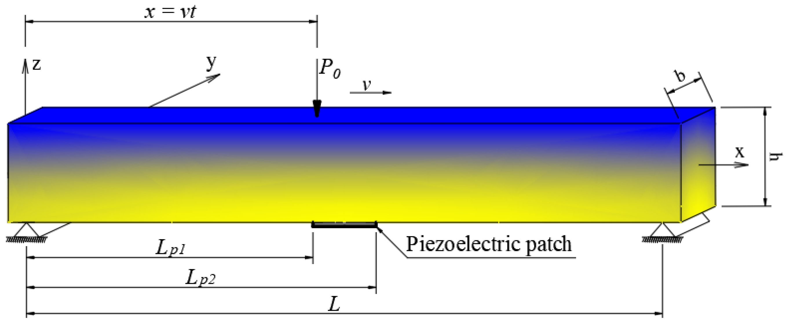
Figure 1. Schematic of the rectangular FGM beam with the coordinate system.
Modelling 06 00055 g001
Figure 2. Simply supported rectangular cross-section beam with a piezoelectric layer bonded on the bottom surface at mid-span, subjected to a moving concentrated load.
Modelling 06 00055 g002
Figure 3. The displacement at the midpoint of the beam. (a) h/L = 1/20 and v = 10 m/s, (b) h/L = 1/20 and v = 20 m/s, (c) h/L = 1/12.5 and v = 10 m/s, and (d) h/L = 1/12.5 and v = 20 m/s.
Modelling 06 00055 g003
Figure 4. Piezoelectric output voltage for various speeds of moving. (a) h/L = 1/20 and v = 10 m/s, (b) h/L = 1/20 and v = 20 m/s, (c) h/L = 1/12.5 and v = 10 m/s, and (d) h/L = 1/12.5 and v = 20 m/s.
Modelling 06 00055 g004
Figure 5. Piezoelectric output power. (a) h/L = 1/20 and v = 10 m/s, (b) h/L = 1/20 and v = 20 m/s, (c) h/L = 1/12.5 and v = 10 m/s, and (d) h/L = 1/12.5 and v = 20 m/s.
Modelling 06 00055 g005
Figure 6. Voltage of energy harvesting from the FGM beam and the material gradation index n =1,2,5. (a) The velocity of the moving load v =10 m/s, and (b) the velocity of the moving load v = 20 m/s.
Modelling 06 00055 g006
Figure 7. The power of energy harvesting from the FGM beam with the material gradation index n =1,2,5. (a) The velocity of the moving load v = 10 m/s, and (b) the velocity of the moving load v = 20 m/s.
Modelling 06 00055 g007
Figure 8. The voltage and power of energy harvesting from the FG beam with various velocities v = 10 m/s, 15 m/s, 20 m/s. (a) The voltage power of energy harvesting, and (b) the power of energy harvesting.
Modelling 06 00055 g008
Table 1. Properties of piezoelectric material.
Description ParameterNumerical Value
Permittivity component e 33 S 9.57 nF / m
Plane stress piezoelectric stress constant e 31 16 C / m 2
High of piezoceramic patch h p 0.0002 (m)
Width of piezoceramic patch b p 0.05 (m)
Disclaimer/Publisher’s Note: The statements, opinions and data contained in all publications are solely those of the individual author(s) and contributor(s) and not of MDPI and/or the editor(s). MDPI and/or the editor(s) disclaim responsibility for any injury to people or property resulting from any ideas, methods, instructions or products referred to in the content.