Article

Finite Element-Based Multi-Objective Optimization of a New Inclined Oval Rolling Pass Geometry

1
Department of Technological Machines and Transportation, Karaganda Industrial University, Temirtau 101400, Kazakhstan
2
Department of Transport Equipment and Logistics, Toraighyrov University, Pavlodar 140008, Kazakhstan
*
Author to whom correspondence should be addressed.
Modelling 2025, 6(3), 110; https://doi.org/10.3390/modelling6030110
Submission received: 25 August 2025 / Revised: 11 September 2025 / Accepted: 15 September 2025 / Published: 22 September 2025

Abstract

A novel rolling scheme incorporating an inclined oval-caliber configuration is proposed to enhance plastic deformation mechanisms in the traditional oval–round rolling sequence. Finite Element Method (FEM) simulations were performed using DEFORM-3D to evaluate and optimize this new scheme across multiple objectives: maximizing average effective strain, minimizing strain non-uniformity (captured via the standard deviation of effective strain), and minimizing rolling force. Numerical modeling was conducted for calibration angles of γ = 0°, 25°, 35°, and 45°, from which Pareto-optimal solutions were identified based on classical non-dominance criteria. Pairwise 2D projections of the Pareto front enabled visualization of trade-offs and revealed γ = 35° as the Pareto knee-point, representing the most balanced compromise among high deformation intensity, increased uniformity, and reduced energy consumption. This optimal angle was further corroborated through a normalized weighted sum of the objective functions. The findings provide a validated reference for designing prototype deforming tools and support future experimental validation.

1. Introduction

In modern continuous rolling mills for round bars and rods, the “round–oval–round” pass sequence is widely used due to its simple groove design, even material flow, excellent surface quality, and ease of die implementation [1]. However, this traditional scheme has three critical drawbacks: it induces radial and circumferential deformation heterogeneity, resulting in uneven microstructural and mechanical properties; it promotes progressive surface-layer micro-damage (e.g., pores and microvoids), impairing product uniformity and reliability; and it restricts elongation per pass, limiting final diameter reduction and the ability to correct casting defects [2,3,4]. These technological limitations call for enhanced gauge design or more advanced pass schemes.
A compelling solution lies in incorporating severe plastic deformation (SPD) principles, which significantly boost shear deformation and foster a homogeneous microstructure, surface defect suppression, and substantial grain refinement [5,6,7]. Segal’s seminal work demonstrates that intense shear enables accumulation of high strain without workpiece failure, enhancing material hardening and uniformity [8,9,10]. Adapting these SPD strategies to oval–round rolling—by altering geometry and orientation—offers a promising pathway to overcoming the above limitations.
Indeed, non-diagonal, diamond-shaped calibers generate counter-flowing plastic streams that intensify shear, promoting microstructural refinement and mechanical uniformity [11,12,13]. The underlying mechanism—achieving relative displacement between workpiece zones—can similarly be activated in oval systems by modifying the geometry or orientation of the oval caliber. Following this principle, we propose an inclined oval geometry, where the oval’s symmetry axes are tilted relative to the roll axis (see Figure 1). This configuration combines heightwise compression with significant transverse shear, markedly enhancing the overall shear component versus conventional oval gages.
Tuning the inclination angle is essential to balance compression and shear, minimize inhomogeneities, and suppress defects. For example, in three-roll planetary rolling of stainless steel tubes, an optimal roll tilt of approximately 9° (within a 7°–11° range) yielded the most uniform stress distribution and geometric accuracy [14]. Analogously, selecting an optimal angle in the inclined oval-round scheme can enhance sectional uniformity and mechanical properties.
Given the challenge of accurately measuring key parameters such as strain distribution, rolling forces, and stress–strain heterogeneity in experimental hot-rolling setups—due to their complexity, high cost, and significant material requirements—numerical modeling using the finite element method (FEM) offers a powerful and cost-effective alternative [15]. FEM allows for precise reconstruction of deformation and stress fields, prediction of how oval inclination influences process behavior, decreased reliance on physical trials, and enhanced reliability in optimizing process parameters. Its effectiveness is demonstrated across various applications: modeling of hot rolling in variable cross-section steel using DEFORM-3D [16]; mesh-refined, computation-efficient FEM for ferritic stainless steel slabs [17]; thermomechanical prediction of aluminum crown profiles using LS-DYNA [18]; and comprehensive simulation of a full 25-pass hot-rolling cycle for beam profiles, enabling identification of critical passes with peak loads and suggesting potential pass reductions without sacrificing geometric quality [19]. Similarly, in oval–round configurations, FEM has been shown to deliver high-fidelity process improvements, such as reduced rolling torque and enhanced area-reduction ratios [20,21,22,23]. Notably, the FEM predictions in the round–oval–round pass design—showing over 6% reduction in rolling torque and up to 11% increase in area-reduction ratio—were experimentally confirmed in full-scale rolling trials, attesting to the accuracy and reliability of the numerical modeling approach [20].

2. Numerical Modeling of Rolling in Oval Calibers

For the numerical investigation of the rolling process in oval calibers, the SFTC DEFORM-3D software package (SFTC, Columbus, OH, USA) was employed. This tool enables the calculation of comprehensive process characteristics—such as stress, temperature, and strain distributions, along with other quantitative indicators—and allows their use as optimization criteria when selecting the optimal tilt angle of the oval caliber. The chosen software package has a well-documented track record of successful applications in modern peer-reviewed publications on rolling and forming processes [24,25,26].
For the initial feasibility assessment of the new rolling scheme with tilted oval calibers, the following assumptions and simplifications were applied:
  • Tool definition—the rolls were modeled as perfectly rigid bodies with surfaces of constant temperature (20°—the default roll temperature in the simulation software). This setup is widely used in FEM simulations of hot rolling since elastic deformations and thermal fluctuations of the rolls have only a minor influence on the overall metal flow field. Their exclusion significantly reduces computational costs. Examples include 3D solvers with rigid–viscoplastic formulations implemented in DEFORM-3D and other FEM packages [27,28].
  • Workpiece material—assumed to be homogeneous and isotropic, with deformation modeled as viscoplastic flow. In hot rolling, the metal structure rapidly homogenizes due to dynamic recrystallization, which reduces anisotropy. Therefore, the use of isotropic viscoplastic models (e.g., Hoff–Norton type) adequately captures the main technological effects while allowing the focus to remain on flow kinematics and shear processes [24,28].
The adopted assumptions and simplifications make it possible to focus on the key task of identifying the feasibility of inducing alternating macro-shear deformations in the “oval–round” system with reasonable computational resources, serving as a reliable foundation for the primary validation of the model before moving on to such factors as heat transfer, tool elasticity, and structural anisotropy.
The billet material used in the rolling simulation was AISI 1045 steel, sourced from the DEFORM-3D material library. Its high-temperature deformation behavior, specifically at 1200 °C, is represented by flow stress curves derived from the library data (see Figure 2). The chemical composition of the alloy is given in Table 1 [29]. These details ensure a transparent and accurate representation of AISI-1045’s behavior under high-temperature, high-strain-rate rolling conditions. AISI 1045 steel was deliberately chosen as a representative medium-carbon structural material, widely employed for automotive components (such as gears and shafts), machinery parts, and toolmaking, owing to its well-documented deformation behavior and the availability of validated constitutive models under high-temperature and high-strain-rate conditions [30].
For our simulation, a temperature of 1200 °C was selected, lying at the upper boundary of the model range, which corresponds to the most effective conditions for the formation of macro-shear deformations in the “oval–round” scheme. This ensures maximum material plasticity and minimizes deformation resistance, while fully realizing the potential of active shear components in the deformation zone.
The simulation was carried out for the process of rolling an initial round billet in oval passes. The billet diameter was 20 mm, the roll diameter was 150 mm, and the elongation coefficient was 1.3. The choice of billet and roll diameters was determined by the technical capabilities of the laboratory rolling mill, where subsequent experimental studies are planned.
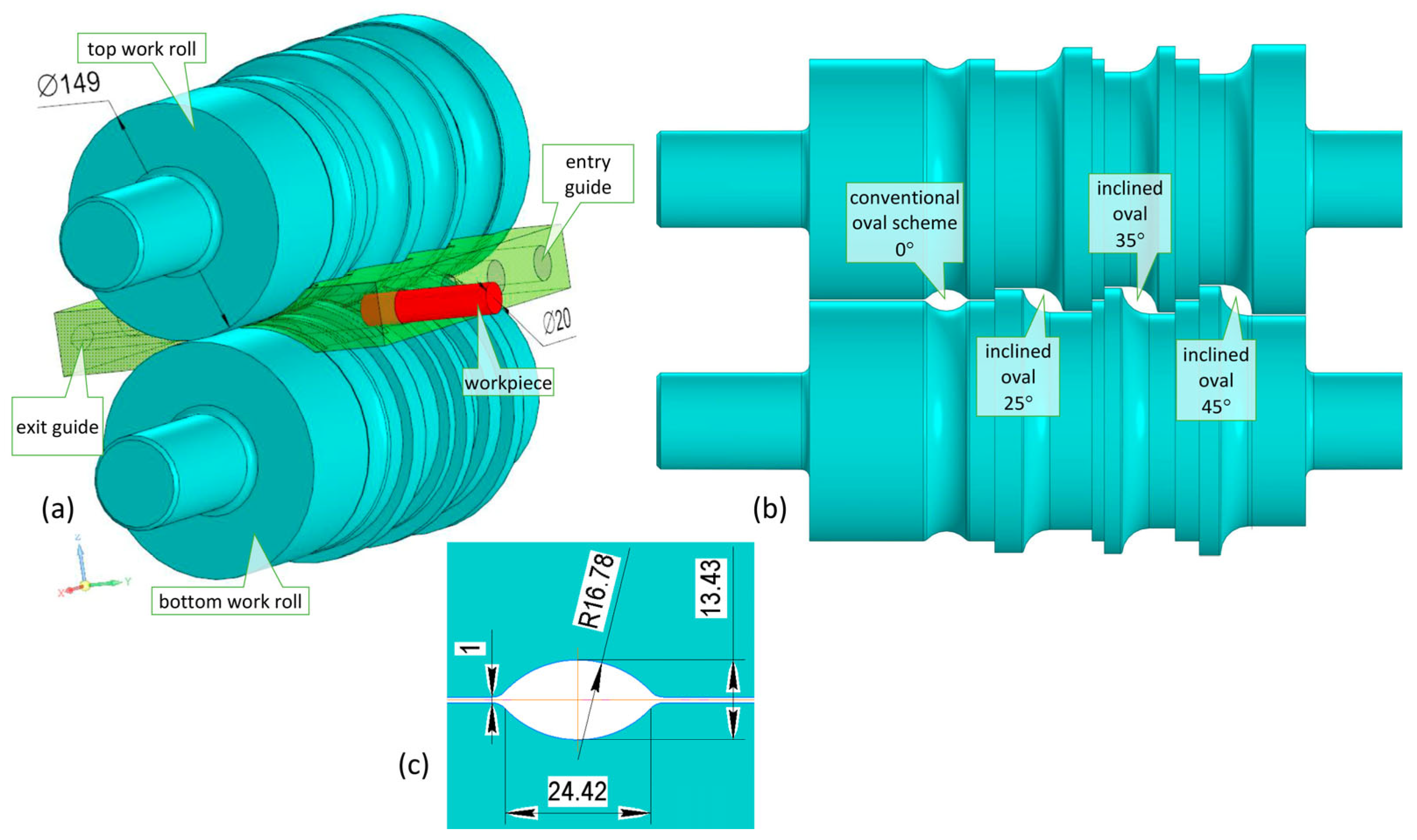
For the purposes of comparative analysis, simulations were performed with oval pass inclination angles of 0° (conventional oval pass), 25°, 35°, and 45°, which makes it possible to determine the range of inclinations at which the realization of macro-shear deformation is most effective. The geometric models of the tools and billets (Figure 3) were built in the CAD system KOMPAS-3D (Russia) based on the groove geometry calculations performed according to the established methodology [31].
Friction at the tool–workpiece interface was described using the Siebel law with a constant friction factor of μ = 0.7, a value recommended by DEFORM-3D for hot metal forming processes under dry friction conditions. The deformation rolls were set to rotate at a constant speed of 1.0472 rad/s, in accordance with the parameters of the laboratory rolling mill used.
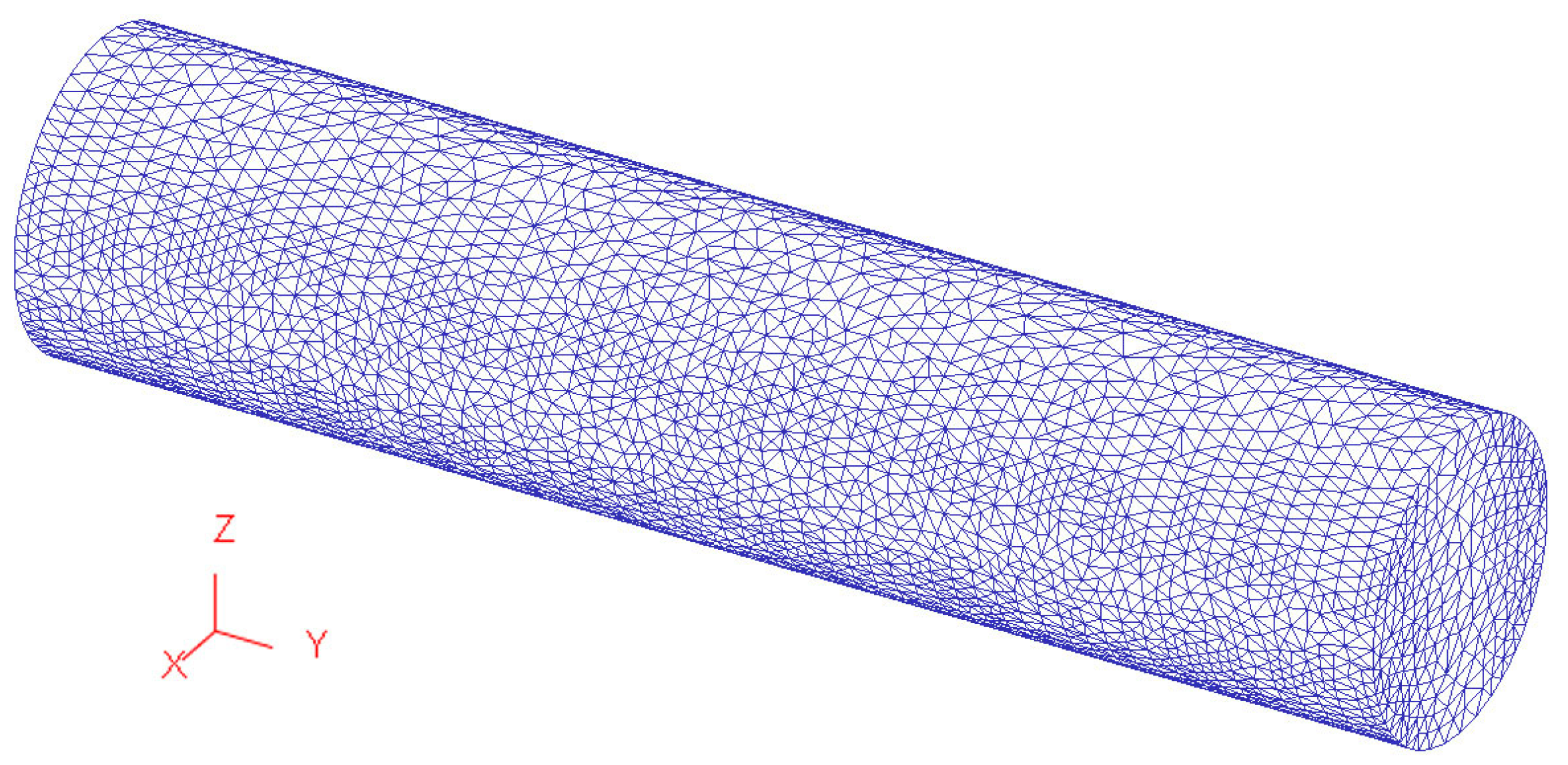
To ensure reliable numerical accuracy, a tetrahedral mesh consisting of approximately 55,818 elements was used, generated automatically within DEFORM-3D (Figure 4) Tetrahedral elements were selected due to their flexibility in meshing complex volumetric geometries and their capacity for local mesh refinement [32], which is crucial in regions with high deformation gradients—particularly important for simulating plastic deformation processes. The chosen element count provides a balanced discretization for a billet measuring 20 mm in diameter and 150 mm in length, delivering sufficient resolution of strain fields while keeping computational costs manageable [33].
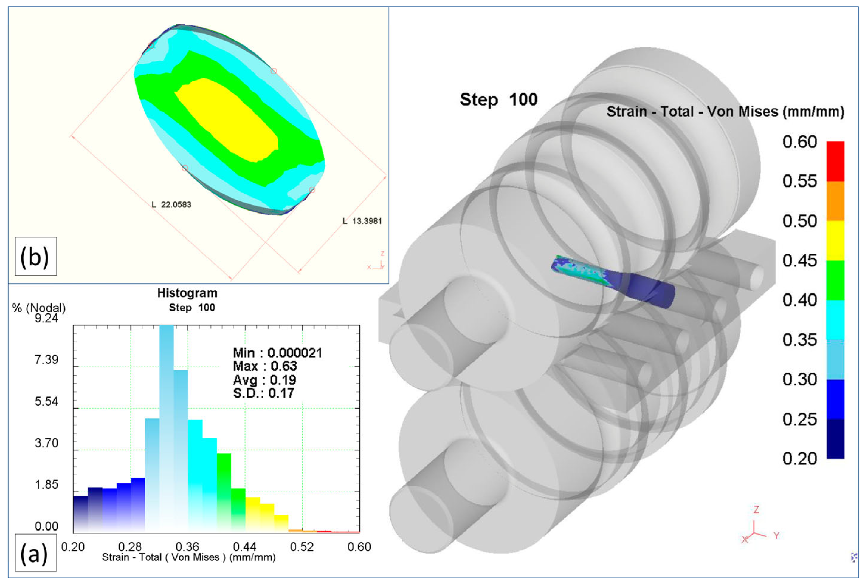
Numerical simulation in the DEFORM-3D software package made it possible to obtain the full range of rolling process characteristics in oval passes, required for evaluating the effectiveness of the proposed scheme. Figure 5 further illustrates these results by showing (a) the DEFORM-3D post-processor histogram of effective (von Mises) strain values, including the calculated minimum, maximum, average, and standard deviation, and (b) the final billet cross-sectional size and shape after rolling.
Special attention in the analysis was given to the distribution of von Mises strain in the transverse section of the strip at the exit of the oval pass (Figure 6). The choice of the transverse section is justified by the fact that the main geometric changes and the manifestation of macro-shear deformation occur in the transverse plane, whereas a longitudinal section does not allow one to capture the characteristic non-uniformity of metal flow across the width and thickness of the profile [34]. The fixation of results at the exit boundary of the pass is due to the fact that in this zone the shape-forming process within the pass is completed, and it is precisely here that the initial conditions for the subsequent transition of the metal into the next pass are established [35]. Thus, the analysis of equivalent strain in the transverse section at the exit of the oval pass makes it possible not only to identify the optimal conditions for the formation of a homogeneous strain field but also to determine the range of inclination angles at which a more uniform metal flow is ensured, and the risks of local stress concentration are reduced.
In the conventional oval groove (0°), the strain distribution exhibits a distinctly symmetric pattern: the central zone is characterized by the highest intensity of plastic flow (0.45–0.5), while the periphery is less involved (0.3–0.35). This distribution reflects the limited effectiveness of inducing macro-shear deformation, which is consistent with the well-documented features of the traditional oval–round pass sequence [1,2,3,4].
At an inclination of 25°, a redistribution of strain intensity zones is observed: the areas of increased deformation shift toward the diagonal directions, and the profile periphery becomes more actively engaged in the process. Nevertheless, the central part still plays a dominant role, although the shear components of deformation are manifested more clearly.
At an inclination of 35°, the zones of maximum strain intensity become more extended and occupy a larger portion of the cross-section, indicating a more uniform plastic flow across the width and thickness of the profile. Such a distribution pattern suggests that 35° can be considered the optimal angle for implementing macro-shear deformation, since sharp local stress concentrations are avoided and a more uniform material flow is ensured in the deformation zone.
In the case of a 45° inclination, extreme development of the shear components is achieved; however, local overload zones (values above 0.55) appear at the edges, which may lead to reduced surface quality and the formation of internal defects. Thus, an excessive inclination angle results in increased heterogeneity of the strain field and higher operational loads on the tool (Figure 7).

3. Multi-Objective Optimization of Inclined Oval-Caliber Angle

In the course of the study, the task was formulated to optimize the parameters of the oval groove, specifically the inclination angle γ, which determines the deformation conditions of the workpiece. The inclination angle of the oval groove γ γ m i n , γ m a x is considered as the optimization variable.
To evaluate the efficiency of the deformation process, three optimization criteria were selected:
1.
The average value of the effective strain in the transverse cross-section at the groove exit, ε ¯ γ , should be maximized. This metric quantitatively represents the overall plastic deformation and energy utilization. It is computed automatically by DEFORM-3D as the arithmetic mean of the effective strain values from all finite elements within the selected cross-sectional plane:
ε ¯ γ = 1 N i = 1 N ε e f f , i ,
where ε e f f , i is the effective strain in the i-th mesh element, and N is the total number of elements in that section.
2.
The standard deviation of the effective strain values, σε(γ), reflects the degree of uniformity of strain across the cross-section and should be minimized, as non-uniform deformation may lead to stress concentrations, structural defects, and reduced product quality. In DEFORM-3D, this statistic is computed automatically for all elements within the selected cross-sectional plane. Formally, it is defined as follows:
σ ε γ = 1 N i = 1 N ε e f f , i ε ¯ γ 2 .
3.
The rolling force, F γ , which characterizes the energy consumption of the process and should be minimized to reduce equipment loads and energy costs.
The values of the optimization criteria obtained through numerical simulation are presented in Table 2.
Thus, the optimization problem has a multi-objective nature and can be formulated as follows:
ε ¯ γ m a x , σ ε γ m i n , F γ m i n , γ γ m i n , γ m a x , g j γ 0 , j = 1 , , m , ,
where g j γ represents the constraints reflecting technological and geometric conditions of the rolling process.
This problem statement can be correlated with the work of Huang et al. [36], where a multi-objective optimization of the oval–round pass design was proposed with the objectives of minimizing power consumption, geometric deviations, and unevenness of contact arcs, using an efficient genetic algorithm for its solution.
Since the criteria are conflicting, the solution must be sought within the Pareto-optimal region, which ensures a compromise between deformation uniformity, its intensity, and the minimization of rolling force. To select a single optimal inclination angle, scalarization methods are appropriate—for example, the weighted aggregation of normalized criteria, which allows for consideration of the priority of individual indicators. The weighted sum method, being a general and easily implemented scalarization approach for multi-objective problems, provides a single solution that reflects the given preferences [37].
In engineering applications, including rolling processes, evolutionary algorithms such as NSGA-II are actively used for constructing the Pareto front and subsequently selecting a compromise solution depending on technological requirements [38].
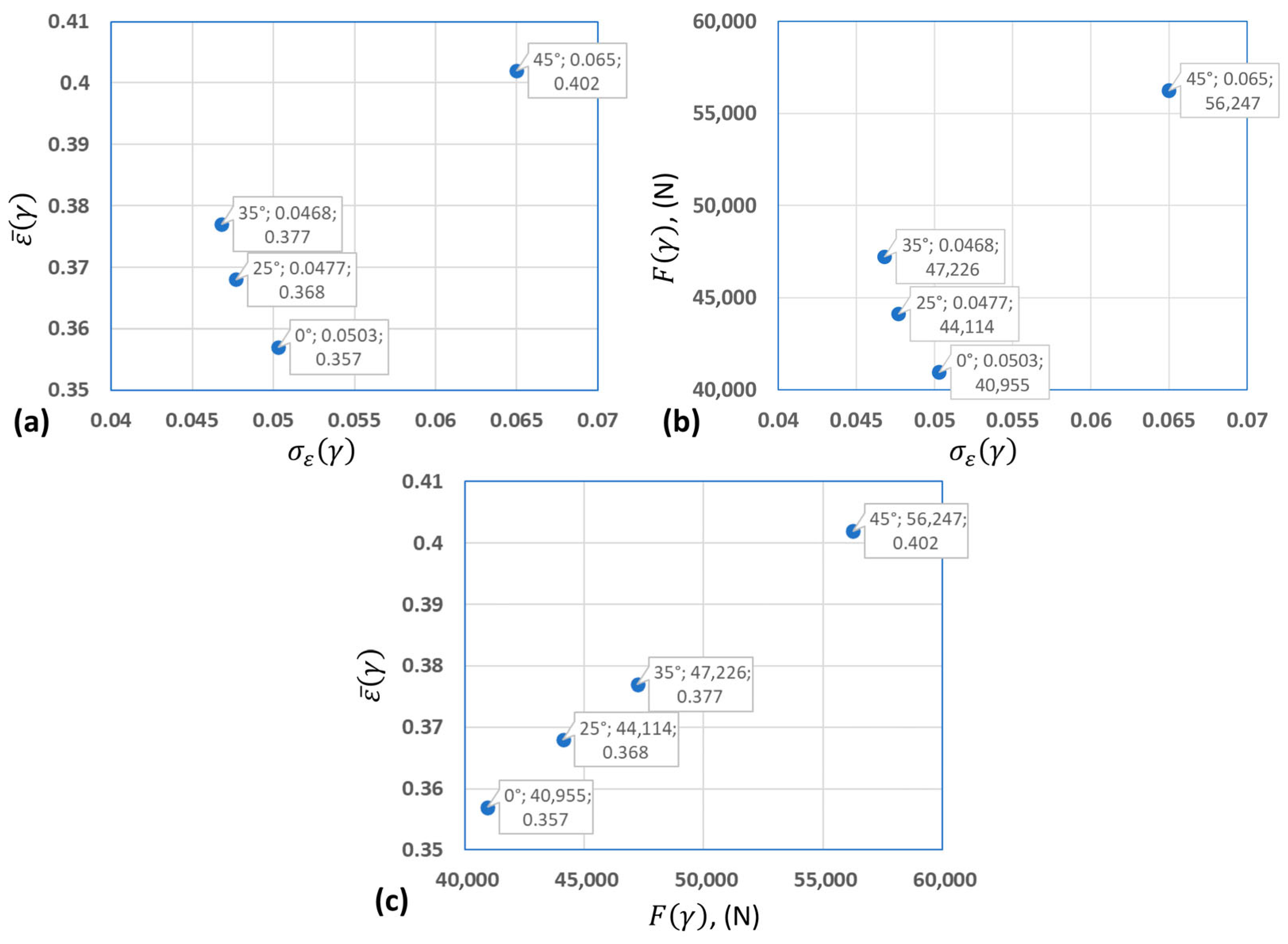
Based on the numerical evaluations presented in Table 2, a Pareto-optimality check was performed. A solution is considered non-dominated if no alternative solution exists that is not worse in all criteria and strictly better in at least one, which corresponds to the commonly accepted definition of multi-objective optimization [39]. To illustrate the trade-offs between objectives, pairwise two-dimensional diagrams were constructed: ε ¯ γ vs. σ ε γ e, F γ vs. σ ε γ , and ε ¯ γ vs. F γ (Figure 8). The analysis of these projections made it possible to identify γ = 35° as the knee-point of the Pareto front—that is, the point where further improvement in one criterion results in a noticeable deterioration of others, which corresponds to the general practice of multi-objective optimization [40].
To solve the optimization problem using the scalarization method (weighted sum), the criteria were normalized, and an objective function was formulated.
The normalization of the three heterogeneous criteria ε ¯ γ , σ ε γ , F γ was carried out based on their minimum and maximum values in the following form:
ε ¯ ~ γ k = ε ¯ γ k m i n j ε ¯ γ j m a x j ε ¯ γ j m i n j ε ¯ γ j ,
σ ~ γ k = σ γ k m i n j σ γ j m a x j σ γ j m i n j σ γ j ,
F ~ γ k = F γ k m i n j F γ j m a x j F γ j m i n j F γ j ,
Here, k = 1, …, 4 corresponds to the variants γ = {0°, 25°, 35°, 45°}.
Such normalization brings the criteria to a unified dimensionless range {0, 1}, which is necessary for their correct combination in a single expression.
When forming the compromise function, a weighted sum of the normalized functions with equal weights ( w 1 = w 2 = w 3 ) was used:
J γ k = 1 3 1 ε ¯ ~ γ k + 1 3 σ ~ γ k + 1 3 F ~ γ k ,
Here, the substitution of ε ¯ ~ γ k with 1 ε ¯ ~ γ k is due to the need to convert the maximization problem of ε ¯ γ into a minimization format, consistent with the other criteria.
The calculation results obtained from Formulas (4)–(7) are presented in Table 3 and visualized in Figure 9.
The scalarization approach demonstrated that the inclination angle γ = 35° represents the optimal compromise among the considered alternatives.
The result of scalarization (weighted aggregation of normalized criteria) is consistent with the Pareto analysis, confirming the status of this alternative as the preferred compromise solution when all objectives are assigned equal priority. This consistent outcome corresponds to theoretical expectations: a priori scalarization methods (such as the weighted sum method) yield Pareto-optimal solutions and, with proper normalization and weight selection, naturally identify knee regions of the front as the “most advantageous” compromise points.
The obtained numerical results for optimizing the oval groove inclination angle have direct practical significance in the design of deforming tools with optimal geometry. Such tools can be manufactured with an inclination angle of γ = 35°, enabling a balanced combination of high-intensity deformation, uniformity, and reduced rolling force. This groove geometry serves as a reference point for further experimental investigations—for example, in evaluating microstructural changes, rolling accuracy, and related aspects.

4. Conclusions

This study introduces a novel inclined oval-caliber rolling scheme that synergistically combines axial compression with transverse shear to promote more uniform and intensive plastic deformation across the billet cross-section. Finite Element Method (FEM) simulations were carried out using DEFORM-3D for four inclination angles (γ = 0°, 25°, 35°, 45°), targeting three conflicting optimization criteria: maximizing the average effective strain ε ¯ , minimizing deformation non-uniformity (standard deviation σ ε ), and minimizing rolling force F .
The simulated data were processed using Pareto-optimal analysis, where classical non-domination criteria identified a Pareto front representing feasible trade-offs between the three objectives. Pairwise 2D projections of this front— ε ¯ vs. σ ε , F vs. σ ε , and ε ¯ vs. F —enabled visualization of the trade-off structure. Across all projections, the inclination angle γ = 35° consistently emerged as the Pareto knee-point, providing a well-balanced compromise: higher deformation intensity, improved uniformity, and manageable rolling force.
To substantiate this finding, a normalized weighted-sum scalarization approach—using equal weights for all criteria—also selected γ = 35° as the optimal angle.
The outcome offers a credible, data-driven recommendation for the design of prototype deforming tools. By specifying γ = 35° as the optimal calibration angle, researchers and practitioners can significantly narrow the experimental parameter space, reducing resource requirements for future validation studies.
Future work will focus on refining the optimization by exploring inclination angles in the vicinity of the current optimum—such as 30° and 40°—with subsequent experimental study of the process at the refined optimal angle, alongside investigations into process robustness under varied material and operational conditions and the extension of the approach to industrial-scale rolling equipment design.

Author Contributions

K.N.: conceptualization; methodology; investigation; writing—original draft preparation; visualization. A.K.: methodology; investigation; formal analysis; data processing. M.A.: methodology; formal analysis; investigation. Z.A.: investigation; formal analysis; methodology. N.S.: investigation; writing—review and editing. S.K.: methodology; formal analysis; data processing. All authors have read and agreed to the published version of the manuscript.

Funding

This research was funded by the Science Committee of the Ministry of Science and Higher Education of the Republic of Kazakhstan (Grant No. AP19674502).

Data Availability Statement

The original contributions presented in this study are included in the article. Further inquiries can be directed to the corresponding author.

Conflicts of Interest

The authors declare no conflicts of interest.

References

  1. Bayoumi, L.S.; Lee, Y. Effect of interstand tension on roll load, torque and workpiece deformation in the rod rolling process. J. Mater. Process. Technol. 2004, 145, 7–13. [Google Scholar] [CrossRef]
  2. Hwang, J.-K. Hardening and softening behavior of caliber-rolled wire. Mater 2022, 15, 2939. [Google Scholar] [CrossRef]
  3. Schowtjak, A.; Wang, S.; Hering, O.; Clausmeyer, T.; Lohmar, J.; Schulte, R.; Ostwald, R.; Hirt, G.; Tekkaya, A.E. Prediction and analysis of damage evolution during caliber rolling and subsequent cold forward extrusion. Prod. Eng. 2019, 14, 33–41. [Google Scholar] [CrossRef]
  4. Hába, J.; Fabík, R. Optimizing of the degree of elongation in a single pass during hot bars rolling in the oval-round roll pass schedule. In Proceedings of METAL 2016 Conference; Technical University of Ostrava, Faculty of Metallurgy and Materials Engineering: Ostrava, Czech Republic, 2016; p. 285. Available online: https://www.confer.cz/metal/2016/read/1747-optimizing-of-the-degree-of-elongation-in-single-pass-during-hot-bars-rolling-in-the-oval-round-roll-pass-schedule.pdf (accessed on 8 August 2025).
  5. Zayed, E.M.; El-Sabbagh, A.; El-Mahallawy, N.A.; Shazly, M. Deformation behavior and properties of severe plastic deformation techniques for bulk materials: A review. Heliyon 2023, 9, e16700. [Google Scholar] [CrossRef]
  6. Bagherpour, E.; Pardis, N.; Reihanian, M.; Kim, H.S. An overview on severe plastic deformation: Research status, techniques classification, microstructure evolution, and applications. Int. J. Adv. Manuf. Technol. 2019, 100, 1647–1694. [Google Scholar] [CrossRef]
  7. Dolzhenko, P.; Tikhonova, M.; Odnobokova, M.; Kaibyshev, R.; Belyakov, A. Ultrafine-grained stainless steels after severe plastic deformation. Metals 2023, 13, 674. [Google Scholar] [CrossRef]
  8. Segal, V. Severe plastic deformation: Simple shear versus pure shear. Mater. Sci. Eng. A 2002, 338, 331–344. [Google Scholar] [CrossRef]
  9. Segal, V. Review: Modes and processes of severe plastic deformation (SPD). Materials 2018, 11, 1175. [Google Scholar] [CrossRef] [PubMed]
  10. Segal, V.M. Deformation mode and plastic flow in ultra fine grained metals. Mater. Sci. Eng. A 2005, 406, 205–216. [Google Scholar] [CrossRef]
  11. Naizabekov, A.B.; Bykhin, M.B.; Nogaev, K.A.; Bykhin, B.B. Study of the process of realization of high-rate plastic deformation in lengthwise rolling. In Proceedings of the 19th International Conference on Metallurgy and Materials (METAL 2010), Brno, Czech Republic, 18–20 May 2010; pp. 192–202. [Google Scholar]
  12. Abishkenov, M.; Ashkeyev, Z.; Nogaev, K. Investigation of the shape rolling process implementing intense shear strains in special diamond passes. Materialia 2022, 26, 101573. [Google Scholar] [CrossRef]
  13. Ashkeyev, Z.; Abishkenov, M.; Nogaev, K.; Bestembek, Y.; Azimbayev, K.; Tavshanov, I. Stress state of workpieces during upsetting with additional shear. Eng. Solid Mech. 2023, 11, 253–262. [Google Scholar] [CrossRef]
  14. Ma, C.; Li, T.; Xue, C.; Jin, R.; Chu, Z.; Shuai, M.; Tuo, L. Optimization of roll configuration and investigation of forming process in three-roll planetary rolling of stainless steel seamless tubes. Metals 2025, 15, 540. [Google Scholar] [CrossRef]
  15. Ojeda-López, A.; Botana-Galvín, M.; González-Rovira, L.; Botana, F.J. Numerical Simulation as a Tool for the Study, Development, and Optimization of Rolling Processes: A Review. Metals 2024, 14, 737. [Google Scholar] [CrossRef]
  16. Montemayor-de la Garza, K.; Zambrano-Robledo, P.d.C.; Zapata-Hernandez, O.J.; Leduc-Lezama, L.A. Finite Element Modeling of Hot Rolling of 1075 Carbon Steel Process with Variable Cross Section. Materials 2022, 16, 2. [Google Scholar] [CrossRef]
  17. Ojeda-López, A.; Botana-Galvín, M.; Collado-García, I.; González-Rovira, L.; Botana, F.J. Finite Element Simulation of Hot Rolling for Large-Scale AISI 430 Ferritic Stainless-Steel Slabs Using Industrial Rolling Schedules—Part 1: Set-Up, Optimization, and Validation of Numerical Model. Materials 2025, 18, 383. [Google Scholar] [CrossRef] [PubMed]
  18. Gavalas, E.; Papaefthymiou, S. Prediction of Plate Crown during Aluminum Hot Flat Rolling by Finite Element Modeling. J. Manuf. Mater. Process. 2019, 3, 95. [Google Scholar] [CrossRef]
  19. Pérez-Alvarado, A.; Arreola-Villa, S.A.; Calderón-Ramos, I.; Servín Castañeda, R.; Mendoza de la Rosa, L.A.; Chattopadhyay, K.; Morales, R. Numerical Simulation of the Hot Rolling Process of Steel Beams. Materials 2021, 14, 7038. [Google Scholar] [CrossRef]
  20. Rashad, M.; Magdi, A.; Ahmed, M.E.; Metwalli, S.M. Optimal design of round-oval-round roll pass for the steel bar rolling process. J. Eng. Appl. Sci. 2024, 71, 224. [Google Scholar] [CrossRef]
  21. Kotas, M.; Fabík, R.; Gajdzica, T.; Kliber, J. Finite Elements Method (FEM) Simulation of Bar Rolling in Oval–Circle Pass Schedule. In Proceedings of the 19th International Conference on Metallurgy and Materials—METAL 2010, Roznov pod Radhostem, Czech Republic, 18–20 May 2010. [Google Scholar]
  22. Moon, C.H.; Lee, Y. Analytical model to predict the free surface profile of outgoing material in oval-to-round pass rolling when cross-section of incoming material is not circular and roll gap changes. ISIJ Int. 2023, 63, 111–119. [Google Scholar] [CrossRef]
  23. Kawano, M.; Isogawa, S.; Kawanishi, K. Evaluation of roll pass designs by thermal mechanical FEM simulation. DENKI-SEIKO 1999, 70, 255–260. [Google Scholar] [CrossRef]
  24. González-Castillo, A.C.; Cruz-Rivera, J.d.J.; Ramos-Azpeitia, M.O.; Garnica-González, P.; Garay-Reyes, C.G.; Pacheco-Cedeño, J.S.; Hernández-Rivera, J.L. 3D-FEM simulation of hot rolling process and characterization of the resultant microstructure of a light-weight Mn steel. Crystals 2021, 11, 569. [Google Scholar] [CrossRef]
  25. Kainz, A.J.; Ilie, S.; Parteder, E.; Zeman, K. From slab corner cracks to edge-defects in hot rolled strip: Experimental and numerical investigations. Steel Res. Int. 2008, 79, 861–867. [Google Scholar] [CrossRef]
  26. Gu, S.D.; Ruan, J.H.; Zhang, L.W.; Yue, C.X.; He, W.B.; Chen, H. 3D FE modelling of plate shape during heavy plate rolling. Ironmak. Steelmak. 2014, 41, 199–205. [Google Scholar] [CrossRef]
  27. Jiang, Z.Y.; Tieu, A.K. Modelling of the rolling processes by a 3-D rigid plastic/visco-plastic finite element method. Int. J. Mech. Sci. 2001, 79, 2727–2740. [Google Scholar] [CrossRef]
  28. Gangopadhyay, T.; Ohdar, R.K.; Pratihar, D.K.; Basak, I. Three-dimensional finite element analysis of multi-stage hot forming of railway wheels. Int. J. Adv. Manuf. Technol. 2011, 53, 301–312. [Google Scholar] [CrossRef]
  29. AISI 1045 Medium Carbon Steel. Available online: https://www.azom.com/article.aspx?ArticleID=6130 (accessed on 9 September 2025).
  30. Jantepa, N.; Siripath, N.; Suranuntchai, S. Predictive Modeling and Optimization of Hot Forging Parameters for AISI 1045 Ball Joints Using Taguchi Methodology and Finite Element Analysis. Metals 2024, 14, 1198. [Google Scholar] [CrossRef]
  31. Wusatowski, Z. Fundamentals of Rolling: Principles of Roll-Pass Design, Illustrated ed.; Pergamon Press: Oxford, UK, 1969; pp. 99–121. [Google Scholar] [CrossRef]
  32. Eisenträger, S.; Duvigneau, F.; Gabbert, U. The Finite Cell Method for Tetrahedral Meshes. Finite Elem. Anal. Des. 2016, 121, 18–32. [Google Scholar] [CrossRef]
  33. Flanagan, F.; O’Connor, A.N.; Erfanian, M.; Music, O.; Brambley, E.J.; O’Kiely, D. Careful Finite Element Simulations of Cold Rolling with Accurate Through-Thickness Resolution and Prediction of Residual Stress. arXiv 2024, arXiv:2408.03242. [Google Scholar] [CrossRef]
  34. Hwang, J.-K. Effect of contact pressure on strain distribution during compression-type bulk forming processes. Materials 2023, 16, 5041. [Google Scholar] [CrossRef]
  35. Sheu, J.-J.; Ho, C.-J.; Yu, C.-H.; Kao, C.-Y. High-order groove-shape curve roll design for aluminum alloy 7075 wire rolling. Metals 2022, 12, 1071. [Google Scholar] [CrossRef]
  36. Huang, B.; Xing, K.; Abhary, K.; Spuzic, S. Optimization of oval–round pass design using genetic algorithm. Robot. Comput.-Integr. Manuf. 2012, 28, 493–499. [Google Scholar] [CrossRef]
  37. Marler, R.T.; Arora, J.S. The weighted sum method for multi-objective optimization: New insights. Struct. Multidiscipl. Optim. 2010, 41, 853–862. [Google Scholar] [CrossRef]
  38. Babajamali, Z.; Khaje Khabaz, M.; Aghadavoudi, F.; Farhatnia, F.; Eftekhari, S.A.; Toghraie, D. Pareto multi-objective optimization of tandem cold rolling settings for reductions and inter-stand tensions using NSGA-II. ISA Trans. 2022, 130, 399–408. [Google Scholar] [CrossRef] [PubMed]
  39. Bejarano, L.A.; Espitia, H.E.; Montenegro, C.E. Clustering analysis for the Pareto optimal front in multi-objective optimization. Computation 2022, 10, 37. [Google Scholar] [CrossRef]
  40. Li, W.; Zhang, G.; Zhang, T.; Huang, S. Knee point-guided multiobjective optimization algorithm for microgrid dynamic energy management. Complexity 2020, 2020, 8877008. [Google Scholar] [CrossRef]
Figure 1. Pass with inclined oval arrangement.
Modelling 06 00110 g001
Figure 2. Flow stress–strain curves for AISI 1045 steel at 1200 °C under different strain rates, based on DEFORM-3D material library data.
Modelling 06 00110 g002
Figure 3. (a) Three-dimensional layout of the top and bottom work rolls, billet, entry guide, and exit guide; (b) configuration of oval groove passes; (c) detailed dimensions of the oval pass.
Modelling 06 00110 g003
Figure 4. Tetrahedral mesh of the Ø20 mm × 150 mm billet showing approximately 55,818 elements, generated automatically in DEFORM-3D.
Modelling 06 00110 g004
Figure 5. (a) DEFORM-3D post-processor output showing effective strain histogram and statistics (Min, Max, Avg, S.D.); (b) final billet geometry—dimensions of the feedstock after rolling.
Modelling 06 00110 g005
Figure 6. Von Mises strain distribution maps in transverse sections at different oval groove inclination angles.
Modelling 06 00110 g006
Figure 7. Force–Time Curves for Inclined Oval Passes (0°, 25°, 35°, 45°).
Modelling 06 00110 g007
Figure 8. Two-dimensional scatter plots of the Pareto front in objective-pair spaces γ = 0°, 25°, 35°, 45°: (a) Average effective strain vs. standard deviation ( ε ¯ γ vs. σ ε γ ). (b) Rolling force vs. variation in effective strain ( F γ vs. σ ε γ ). (c) Average effective strain vs. rolling force ( ε ¯ γ vs. F γ ).
Modelling 06 00110 g008
Figure 9. Compromise function J γ k plot with equal weights.
Modelling 06 00110 g009
Table 1. Chemical composition of AISI 1045 steel (wt.%) [29].
CMnPS
0.42–0.500.60–0.90≤0.040≤0.050
Note: Iron (Fe) constitutes the balance of the material (98.51–98.98%).
Table 2. Values of the optimization criteria obtained through numerical simulation.
CriterionOval Inclination Angle (°)
0253545
ε ¯ γ 0.3570.3680.3770.402
σ ε γ 0.05030.04770.04680.065
F γ , (H)40,95544,11447,22656,247
Table 3. Normalized criteria and values of the function J(γ_k).
γ , (°) ε ¯ ~ γ k σ ~ γ k F ~ γ k J γ k
000.192600.3975
250.24440.04950.20610.3333
350.444400.40610.2835
451110.6667
Disclaimer/Publisher’s Note: The statements, opinions and data contained in all publications are solely those of the individual author(s) and contributor(s) and not of MDPI and/or the editor(s). MDPI and/or the editor(s) disclaim responsibility for any injury to people or property resulting from any ideas, methods, instructions or products referred to in the content.