Abstract
Prosthetic socket manufacturing is experiencing a revolutionary shift towards using digital methods, such as 3D scanning and 3D printing. However, using digital methods requires the clinician to transfer their skills from making sockets by hand to making sockets with a computer. This shift in practice may change the socket geometry and fit; however, to what extent is unknown. Thus, the aim of this study was to explore the feasibility of analyzing geometric and clinical differences between digitally- and manually-designed sockets. Nine adult inpatients with below-knee amputation were recruited. Two sockets were 3D printed for each participant from 3D socket models that were developed from: (1) 3D scanning a manually-modified hand-casted positive mold of the residuum; and (2) a digitally-modified 3D scan of the residuum. Manual and digital procedures were compared for three measures: final socket geometry, the Socket Comfort Score, and a patient experience survey. Feasibility data were collected to measure protocol implementation fidelity to inform a future larger study. These data revealed that 89% of participants followed the intended protocol, no participants dropped out, and only one adverse event was report. As no significant geometric differences were found and participants experienced similar comfort scores between manually- and digitally-designed sockets, study feasibility was determined to be successful. Thus, a randomized control trial study will be conducted to draw statistically relevant conclusions from these outcome measures that may provide meaningful information for improving digital design procedures.
1. Introduction
With the rapid development of virtual healthcare services (known as telemedicine, telerehabilitation, e-Health, and m-Health) across all medical areas, digital technology is playing a significant role in patient assessment and treatment [1,2]. However, clinicians and technicians wonder how this technology may change their clinical roles. Likewise, as patients are exposed to media that promotes the advantages of additive manufacturing (AM)—commonly referred to as 3D printing—for prosthetic and orthotic (P&O) devices, they enquire about AM and expect to receive devices made with such technology. As more clinicians and facilities employ AM, the business model for P&O facilities may need considerable change [3,4,5].
As the connection between human and prosthesis, prosthetic sockets must be custom-made to fit each patient’s unique residual limb. Traditional manufacturing of prosthetic sockets is a high-skill process involving several stages, which are labour-intensive and fully dependent on the skill and expertise of the technician and clinician. Additionally, the artisanal aspect in capturing the residual limb shape and rectifying the positive mold results in inconsistencies between clinicians, and increases the likelihood of human error. Thus, designing prosthetic sockets poses a great opportunity to leverage AM technology since one of its main advantages is to easily fabricate complex, one-off custom parts [6]. On the other hand, using digital scanning to capture the residual limb’s shape does not capture the critical residuum tissue information that is traditionally used to make rectification decisions, thus leading to a fundamentally different approach to prosthetic socket design [7].
While clinicians may be hesitant in their knowledge-transfer from a manual to digital rectification method, sockets designed using computer-aided design (CAD) have still produced successful outcomes [8,9]. However, these studies only compare the differences in clinical outcomes, such as comfort and gait measurements, between CAD and conventional sockets. What is missing is an understanding of the geometric differences and if there is a correlation between geometric differences and clinical outcomes. Furthermore, the CAD software used in the literature varies greatly: socket models have been designed using custom software based on soft tissue compliance [10], engineering CAD tools such as Fusion360 [11], and commercially available P&O CAD software such as OMEGA, Vorum, Orten, and others [3,12,13]. Workflows are relatively similar among the P&O-based CAD software; however, their CAD tools still differ and the final geometry of the socket model will be influenced by the clinician using the software [3,14].
It is well known that there is limited objective clinical evidence to support design choices when rectifying a socket [15], and as we transition to digital rectification, we can quantify these rectifications in the hopes of supporting research to improve clinical outcomes with sockets. Ultimately, what needs to be asked is what is being done to these sockets (geometrically), either globally or at certain anatomical areas (distal tibia, fibular head, etc.), to improve clinical outcomes, if at all? We hypothesize that (1) digitally-designed sockets and manually-designed sockets are geometrically different, (2) the digitally-designed sockets result in better clinical outcomes compared to manually-designed sockets, and (3) improved clinical outcomes correlate to geometric differences at particular regions of the socket. To our knowledge, no studies have been conducted to investigate the differences in socket geometries between sockets designed digitally and manually, and what the resulting clinical outcomes are. Therefore, to answer our hypotheses, a feasibility study is needed to inform an effective protocol for a future randomized controlled trial study.
In this study, we aimed to assess the feasibility of a protocol for investigating if differences in socket geometry due to design method (digitally-designed vs. manually-designed) affect clinical outcomes for individuals with transtibial prostheses. The feasibility criteria were based on: (1) patient recruitment, consent, and retention rates; (2) acceptability of the study procedure to both participants and research facilitators in terms of adherence to timing and schedule; and (3) adverse events. Furthermore, the geometries and socket comfort scores (SCS) [16] are descriptively compared between manually- and digitally-designed sockets, and patient experiences are reported.
2. Materials and Methods
2.1. Socket Design and Manufacturing
Impressions were taken of 9 residual limbs of individuals with transtibial amputation who needed a preparatory prosthesis, using two methods: conventional plaster of Paris and 3D scanning. Participants were positioned on an assessment bed and were instructed to hold their limb still throughout the scanning. Surface reflective markers were placed on anatomical landmarks to help with computer-aided modifications as points of reference (Figure 1). Scanning was performed over the gel liners. If needed, scanning was repeated until a scan that appeared free from major flaws was obtained and selected for further processing. Each scan took approximately 5 min to complete. Participants were then manually casted using conventional methods with the plaster of Paris.
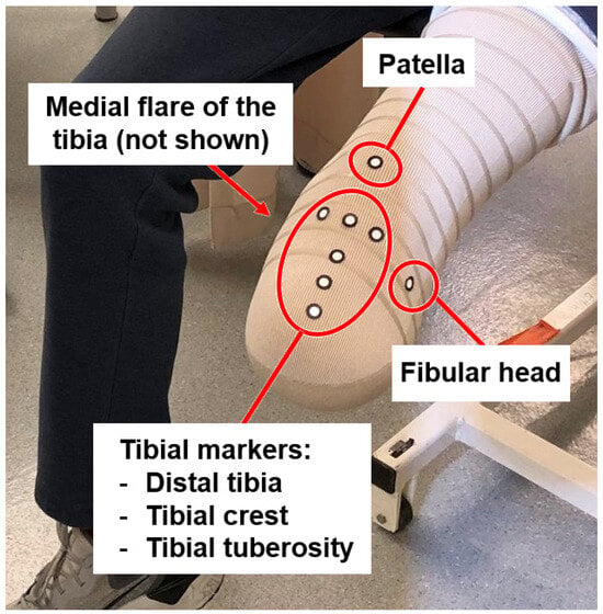
Figure 1.
Surface reflective markers used during 3D scanning.
The clinician manually rectified the positive plaster cast, which was then scanned for digitization (herein, the M-socket). Then, the same clinician digitally rectified the scanned impression of the residuum using OMEGA software (Version: 1.7.2; OMEGA software, WillowWood Global LLC, Mt Sterling, OH, USA) (herein, the CAD-socket). Both scans were taken with an Artec Eva optical scanner and processed in Artec Studio 13. The scanner is accurate to ±0.1 mm and its 3D resolution is ±0.2 mm at a rate of 16 frames per second [17]. The OMEGA software is a commercially available software that has been used to rectify P&O devices since the early 1990s. The clinician has five years of experience using various software for the 3D design of the prosthetic sockets.
The final rectified models were exported to Autodesk Meshmixer, where the final socket models were created with a 4 mm wall thickness. Sockets were Total Surface Bearing (TSB). The M-socket and CAD-socket files were then 3D printed (Stratasys F370) in an ABS thermoplastic (ABS M30, black, F123 Series) at 0.33 mm layer height using 80% infill and 5 contours (Figure 2). Both sockets were 3D printed to blind the patient and clinician. The two 3D-printed sockets were then reinforced and connected to its corresponding component adapters using fiberglass and resin materials, as is done during current standard of care, and to ensure the 3D-printed materials were structurally safe to bear weight. To eliminate confounding, the same suspension (cushion liner, sleeve, and passive suction), shank, and foot components were used. Subjects were given a patient experience survey with each shape-capturing process. The survey was administered by a research assistant using a face-to-face interview technique before they were fitted with the sockets.
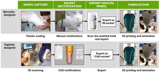
Figure 2.
Design and manufacturing workflow of the manually- and digitally-designed sockets.
Both sockets were fitted to the patient on the same day, and immediate SCS [16] and immediate socket fit were recorded. Subjects then continued the prosthetic training using the socket that was deemed more comfortable and fit better based on both the subject’s judgment and the judgment of their clinician. If the subject found both sockets to be equally comfortable, he/she could choose the preferred socket to continue with for therapy. The subjects were given two days to acclimate to the selected socket.
For each socket, we asked the participants how they felt while walking with the socket and verbal feedback was recorded from a patient experience survey (See Appendix A). Time required for scanning, socket modifications using CAD, and 3D printing were all recorded.
2.2. Analysis and Feasibility Criteria
To obtain the socket measurements, the 3D models were imported to Fusion 360 and sectioned at the patellar tendon bar (PTB), ¼ height, ½ height, and ¾ height planes (Figure 3). The circumference, antero-posterior (AP), and medio-lateral (ML) measurements were then measured at each plane using the software’s measurement tool. The two sockets for each patient were then aligned via an axis that connected the midpoint (meaning the intersection of AP and ML lines) at the PTB plane, and the midpoint at the ¾ height plane. These aligned sockets were then imported to MeshLab for point-by-point comparison. Global average difference and local differences at anatomical areas where rectifications were made were measured.
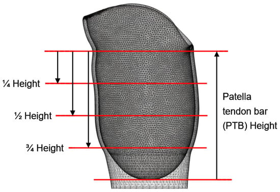
Figure 3.
Section planes used for geometry comparisons.
Success of the feasibility analysis was determined based on the following a priori criteria: recruitment rate >70% of all eligible potential participants; of the participants recruited, <30% deviated from the protocol, allowing for effective collection of quantitative and qualitative data appropriate for use in a randomized controlled trial study; <20% dropped out of the study.
3. Results
3.1. Feasibility
The feasibility measurements are summarized in Table 1. Zero participants dropped out, one participant (11%) deviated from the intended protocol, and one adverse event was reported as the socket cracked on the lateral proximal wall during physiotherapy treatment, requiring reinforcement. No fall or injury was reported.

Table 1.
Feasibility measures.
3.2. Required Resources
Table 2 shows the average time of casting, scanning, and modifications done for each socket. A decrease of 34% when scanning compared to casting was seen. However, the time of digital modification was higher by 92%.

Table 2.
Average time for shape capture, modifications and printing procedures per socket.
3.3. Socket Comfort Scores
Overall, eight out of nine patients were satisfied with the comfort of their digitally-designed socket (Table 3). Unsatisfactory outcomes were a result of inaccurate digital modifications by the clinician, including underestimating the amount of global reduction and improper modifications at the distal end of the model.

Table 3.
Socket comfort scores.
3.4. Socket Geometries
Geometry comparison revealed on average 1.2% greater vertical distance from the residuum distal end to the patellar tendon and 2.1% larger global volume for the manual sockets compared to the digital (Figure 4).
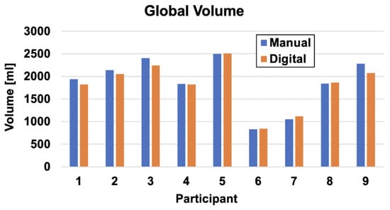
Figure 4.
Global volume differences between manually- and digitally-designed sockets for each participant.
At the PTB level, the differences in circumference and medial-lateral measurements showed similar trends, where manual sockets had larger measurements on average, except in the AP measurement (Table 4). Figure 5 shows very similar measurements of PTB height from the distal end. Five manual sockets had a slightly taller PTB height (participants 1, 2, 3, 4, and 9), and four manual sockets had a slightly shorter PTB height (participants 5, 6, 7, and 8). However, more data are required to make statistical conclusions.

Table 4.
Geometric differences at the PTB between manually- and digitally-designed sockets.
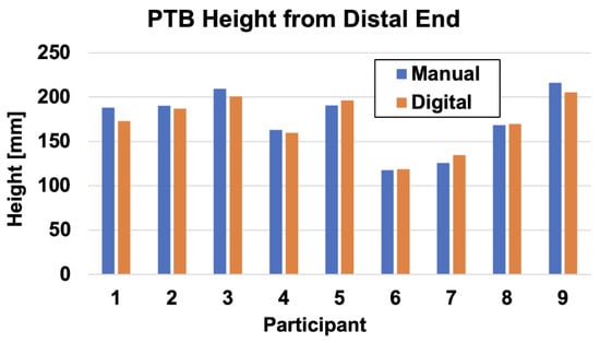
Figure 5.
Differences in PTB height from the distal end between manually- and digitally-designed sockets for each participant.
3.5. Patient Experience
Participants were asked about their opinion on the digital and manual process of shape capture, and their overall experience with each process. All but one participant strongly agreed that they felt comfortable during the digital capture of the limb shape with the scanner. On average, the participants were overall more satisfied with the scanning than manual casting by 7.45% (9.44 vs. 8.77). All but one participant preferred the 3D scanning to the plater casting, but the participant did not give feedback on why they preferred the manual casting.
The participants had equal confidence in the clinician’s ability to capture both an accurate scan and an accurate plaster mold of the limb. When they were asked if they were impressed by the scanning and manual casting, the score was either “strongly agreed” or “agreed” for both methods.
4. Discussion
4.1. Feasibility for a Future RCT
This study showed that the implementation of a larger RCT study to assess the geometric and clinical outcome differences between digitally- and manually-designed sockets is feasible. All of the predefined feasibility criteria were achieved in this study. Since recruitment and retention criteria were achieved, there is no need to reconsider or alter the eligibility criteria.
4.2. Clinical Significance
The digital process for socket manufacturing comprises various stages, each with their own clinical and technical advantages and barriers. 3D scanning has its advantages over conventional mold taking. The surface scan of the residual limb is easily obtained relatively quickly and with high accuracy [7,18]. During the COVID pandemic, the use of virtual clinic consultations became an alternative tool for seeing patients remotely [3,19]. Scanning can take place anywhere remotely, and the information can be sent to the clinician for processing and printing locally, thus reducing unnecessary patient–clinician contact. Furthermore, digital practices facilitate remote teaching of P&O device design in schools.
The patient experience is equally positive and giving them the ability to watch the process on-screen is very engaging. However, what has been reported missing is the tactile feedback the clinician obtains during the conventional, manual casting [3,5,14]. This makes the modifications of the digitally-scanned residuum more challenging for clinicians as their confidence in applying the biomechanical principals is hindered. This is a known barrier to adopting 3D scanning and digital modification procedures [3,14,20]. Furthermore, as clinicians gain experience with CAD, their rectification techniques and socket outcomes may change [14]. In this study, one clinician performed the procedures. However, in a larger study, at least two clinicians should be recruited and perform the protocol for the same set of participants.
Where digital design and manufacturing truly excels is the AM process. The socket is manufactured from start to finish within 9–20 h (depending on its dimensions), eliminating laborious processes which would otherwise obtain the same result [5]. At this point, though, not enough dynamic safety testing has been done to fully trust the strength of the 3D-printed socket without post-reinforcement with the printer used in this study. This reinforcing process is hoped to be redundant in the near future as mechanical properties of AM materials improve, and advanced techniques such as orthogonal print layups and multi-material printing are developed [21]. The reinforcement process increased the overall time of the protocol for this study. One major reason for the use of 3D printing is to save in time; therefore, eliminating the post-processing will be an improvement. Another important factor that needs exploring is the type of 3D printer used, as the print speed, accuracy, and consistency vary greatly depending on the printer.
How appealing would it be to scan a residual limb and walk out in a few hours with a complete device? Printer speeds will need to improve to reach this dream; however, with AM still showing great potential, we need a better understanding of how to use CAD to design sockets with predictable outcomes in order for clinicians to accept it as the go-to tool in their toolbox. Acceptance will be seamless when the digital process produces an equal or better outcome than the traditional methods, with the same level of predictability and confidence.
Barriers and controversies for adopting digital manufacturing practices remain and must be addressed as regulatory requirements are formed [22]. These include the unrealistic projections and exaggerations of anticipated advancements, getting regulatory approval from the appropriate industry regulators, and the ethics of AM applications in research and practice. Inevitably, printers are prone to break down, which may slow down the fabrication process. In our study, the socket production was delayed on two occasions due to a filament jam.
Economic factors, among others, have resulted in testing digitally designed and manufactured P&O devices in low-income countries or less-resourced settings in the past few years. While some research works are compatible with existing institutions, companies, and service providers, research emerging from organizations with non-clinical and non-assistive technology backgrounds may raise considerable concern.
4.3. Study Limitations
We only included inpatients in our study, which may make the generalizability of the results limited and ideally outpatients should be included and compared as well as patients with various causes of amputation. Also, results are not generalizable as it was a feasibility study on a small sample. Another limitation of the study is the method used for aligning and comparing scanned geometries. The chosen alignment axis in this study ensures that the AP-ML intersection at the PTB plane is the aligned reference point between the manual and digital models, and that the longitudinal axis of both models are collinear. However, if a different alignment method was used, such as using a different anatomical reference point, an iterative closest-point algorithm, or a manual method, this would affect the measurements taken.
Another limitation is the use of the SCS as a clinical assessment. The SCS has demonstrated poor reliability and leaves the interpretation of comfort ambiguous [23]. However, it is currently the most widely used comfort score, and apart from a few items in the Comprehensive Lower Limb Amputee Socket Survey, it is the only assessment that specifically addresses comfort [24]. A future study may wish to include additional clinical outcome measures.
Author Contributions
Conceptualization, A.E., C.P., C.M., S.D. and W.H.; methodology, A.E., C.P. and W.H.; formal analysis, A.E., C.P. and W.H.; investigation, A.E., C.P., Z.R. and S.L.; data curation, A.E., C.P., Z.R. and S.L.; writing—original draft preparation, A.E. and C.P.; writing—review and editing, A.E., C.P., C.M., S.D., Z.R., S.L. and W.H.; visualization, C.P.; supervision, W.H. All authors have read and agreed to the published version of the manuscript.
Funding
This research received no external funding. The manuscript publication was supported by the West Park Foundation.
Institutional Review Board Statement
The study was approved by the Joint West Park Healthcare Centre/The Salvation Army Toronto Grace Health Centre Research Ethics Board (20-013-WP; 10 May 2021).
Informed Consent Statement
Informed consent was obtained from all subjects involved in the study.
Data Availability Statement
Data are available on request due to privacy restrictions.
Acknowledgments
The authors extend their gratitude to the West Park Foundation for supporting the publishing of this research article. The authors wish to thank the prosthetic users who contributed to this work at West Park Healthcare Centre.
Conflicts of Interest
The authors declare no conflicts of interest.
Appendix A
Patient Experience Data (attached).
PATIENT EXPERIENCE SURVEY
Date: _________________
Patient ID: _____________________
Clinician/Researcher: ______________________
Study Title: Comparison of socket geometry and clinical outcomes between manually- and digitally-designed prosthetic sockets for lower-limb amputees: a feasibility study
- 1.
- 3D SCANNING SESSION
Please mark the response that most closely reflects your opinion on the 3D scanning session.
| Strongly agree | Agree | Somewhat agree | Somewhat disagree | Disagree | Strongly disagree | |
| Overall, I felt comfortable while the clinician captured my limb with the 3D scanner. | ||||||
| I had concerns during the 3D scanning session. | ||||||
| I had confidence that the clinician captured an accurate 3D scan of my limb. | ||||||
| I was impressed by the 3D scanning technology. | ||||||
| If required, I would not have any issues undergoing the 3D scanning again. | ||||||
| I preferred the 3D scanning to the plaster casting. |
Please rate your overall experience with the 3D scanning session.
Extremely poor experience. Extremely positive experience.
| 1 | 2 | 3 | 4 | 5 | 6 | 7 | 8 | 9 | 10 |
What, if anything, would have improved your experience during the 3D scanning session?
__________________________________________________________________________
Do you have any additional feedback on the 3D scanning session?
__________________________________________________________________________
- 2.
- PLASTER CASTING SESSION
Please mark the response that most closely reflects your opinion on the plaster casting session.
| Strongly agree | Agree | Somewhat agree | Somewhat disagree | Disagree | Strongly disagree | |
| Overall, I felt comfortable while the clinician captured my limb with the plaster cast. | ||||||
| I had concerns during the plaster casting session. | ||||||
| I had confidence that the clinician captured an accurate plaster mold of my limb. | ||||||
| I was impressed by the plaster casting process. | ||||||
| If required, I would not have any issues undergoing the plaster casting again. | ||||||
| I preferred the plaster casting to the 3D scanning. |
Please rate your overall experience with the plaster casting session.
Extremely poor experience. Extremely positive experience.
| 1 | 2 | 3 | 4 | 5 | 6 | 7 | 8 | 9 | 10 |
What, if anything, would have improved your experience during the plaster casting session?
__________________________________________________________________________
Do you have any additional feedback on the plaster casting session?
__________________________________________________________________________
References
- Hernandez, A.; Lemaire, E. A smartphone photogrammetry method for digitizing prosthetic socket interiors. Prosthet. Orthot. Int. 2017, 41, 210–214. [Google Scholar] [CrossRef] [PubMed]
- Dodziuk, H. Applications of 3D printing in healthcare. Pol. J. Cardio-Thorac. Surg. 2016, 13, 283. [Google Scholar] [CrossRef] [PubMed]
- Binedell, T.; Subburaj, K.; Wong, Y.; Blessing, L.T.M. Leveraging digital technology to overcome barriers in the prosthetic and orthotic industry: Evaluation of its applicability and use during the COVID-19 pandemic. JMIR Rehabil. Assist. Technol. 2020, 7, e23827. [Google Scholar] [CrossRef]
- Safari, R. Lower limb prosthetic interfaces: Clinical and technological advancement and potential future direction. Prosthet. Orthot. Int. 2020, 44, 384–401. [Google Scholar] [CrossRef]
- Eshraghi, A.; Phillips, C.; Heim, W. Business practices efficiency: Impact of integrating digital technology on clinical P&O practices. Prosthet. Orthot. Int. 2023, 47, 621–624. [Google Scholar]
- Chen, R.K.; an Jin, Y.; Wensman, J.; Shih, A. Additive manufacturing of custom orthoses and prostheses—A review. Addit. Manuf. 2016, 12, 77–89. [Google Scholar] [CrossRef]
- Dickinson, A.S.; Donovan-Hall, M.K.; Kheng, S.; Bou, K.; Tech, A.; Steer, J.W.; Metcalf, C.D.; Worsley, P.R. Selecting appropriate 3D scanning technologies for prosthetic socket design and transtibial residual limb shape characterization. JPO J. Prosthet. Orthot. 2022, 34, 33–43. [Google Scholar] [CrossRef]
- Karakoç, M.; Batmaz, I.; Sariyildiz, M.A.; Yazmalar, L.; Aydin, A.; Em, S. Sockets manufactured by CAD/CAM method have positive effects on the quality of life of patients with transtibial amputation. Am. J. Phys. Med. Rehabil. 2017, 96, 578–581. [Google Scholar] [CrossRef]
- Öberg, T.; Lilja, M.; Johansson, T.; Karsznia, A. Clinical evaluation of trans-tibial prosthesis sockets: A comparison between CAD CAM and conventionally produced sockets. Prosthet. Orthot. Int. 1993, 17, 164–171. [Google Scholar] [CrossRef]
- Ballit, A.; Mougharbel, I.; Ghaziri, H.; Dao, T.T. Computer-aided parametric prosthetic socket design based on real-time soft tissue deformation and an inverse approach. Vis. Comput. 2022, 38, 919–937. [Google Scholar] [CrossRef]
- Wang, X.; Wang, K.; Hu, Z.; Tian, H. Design of the prosthetic socket and the finite element analysis of the interfacial stress. Chin. J. Tissue Eng. Res. 2020, 24, 862–868. [Google Scholar]
- Afiqah Hamzah, N.; Razak, N.A.; Sayuti Ab Karim, M.; Gholizadeh, H. A review of history of CAD/CAM system application in the production of transtibial prosthetic socket in developing countries (from 1980 to 2019). Proc. Inst. Mech. Eng. Part H J. Eng. Med. 2021, 235, 1359–1374. [Google Scholar] [CrossRef] [PubMed]
- Ibrahim, F.G.; Abu El-Majd, A.E.; Abu El-ezz, R.S. Using CAD-CAM Technology in The Design of Prosthetic Devices. Int. Des. J. 2020, 10, 385–392. [Google Scholar] [CrossRef]
- Ngan, C.C.; Sivasambu, H.; Kelland, K.; Ramdial, S.; Andrysek, J. Understanding the adoption of digital workflows in orthotic & prosthetic practice from practitioner perspectives: A qualitative descriptive study. Prosthet. Orthot. Int. 2022, 46, 282–289. [Google Scholar] [PubMed]
- Dickinson, A.; Diment, L.; Morris, R.; Pearson, E.; Hannett, D.; Steer, J. Characterising residual limb morphology and prosthetic socket design based on expert clinician practice. Prosthesis 2021, 3, 280–299. [Google Scholar] [CrossRef]
- Hanspal, R.S.; Fisher, K.; Nieveen, R. Prosthetic socket fit comfort score. Disabil. Rehabil. 2003, 25, 1278–1280. [Google Scholar] [CrossRef] [PubMed]
- Artec3D. Artec Eva—Specifications. 2021. Available online: https://www.artec3d.com/portable-3d-scanners/artec-eva-v2#specifications (accessed on 2 December 2023).
- Seminati, E.; Talamas, D.C.; Young, M.; Twiste, M.; Dhokia, V.; Bilzon, J.L.J. Validity and reliability of a novel 3D scanner for assessment of the shape and volume of amputees’ residual limb models. PLoS ONE 2017, 12, e0184498. [Google Scholar] [CrossRef] [PubMed]
- Sedigh, A.; Kachooei, A.R.; Beredjiklian, P.K.; Vaccaro, A.R.; Rivlin, M. Safety and efficacy of casting during COVID-19 pandemic: A comparison of the mechanical properties of polymers used for 3D printing to conventional materials used for the generation of orthopaedic orthoses. Arch. Bone Jt. Surg. 2020, 8, 281–285. [Google Scholar] [PubMed]
- Cabrera, I.A.; Pike, T.C.; McKittrick, J.M.; Meyers, M.A.; Rao, R.R.; Lin, A.Y. Digital healthcare technologies: Modern tools to transform prosthetic care. Expert Rev. Med. Devices 2021, 18, 129–144. [Google Scholar] [CrossRef]
- Lunsford, C.; Grindle, G.; Salatin, B.; Dicianno, B.E. Innovations with 3-dimensional printing in physical medicine and rehabilitation: A review of the literature. PM&R 2016, 8, 1201–1212. [Google Scholar]
- Manero, A.; Smith, P.; Sparkman, J.; Dombrowski, M.; Courbin, D.; Kester, A.; Womack, I.; Chi, A. Implementation of 3D printing technology in the field of prosthetics: Past, present, and future. Int. J. Environ. Res. Public Health 2019, 16, 1641. [Google Scholar] [CrossRef] [PubMed]
- Morgan, S.J.; Askew, R.L.; Hafner, B.J. Measurements of best, worst, and average socket comfort are more reliable than current socket comfort in established lower limb prosthesis users. Arch. Phys. Med. Rehabil. 2022, 103, 1201. [Google Scholar] [CrossRef] [PubMed]
- Olsen, J.; Turner, S.; Chadwell, A.; Dickinson, A.; Ostler, C.; Armitage, L.; McGregor, A.H.; Dupan, S.; Day, S. The impact of limited prosthetic socket documentation: A researcher perspective. Front. Rehabil. Sci. 2022, 3, 853414. [Google Scholar] [CrossRef] [PubMed]
Disclaimer/Publisher’s Note: The statements, opinions and data contained in all publications are solely those of the individual author(s) and contributor(s) and not of MDPI and/or the editor(s). MDPI and/or the editor(s) disclaim responsibility for any injury to people or property resulting from any ideas, methods, instructions or products referred to in the content. |
© 2024 by the authors. Licensee MDPI, Basel, Switzerland. This article is an open access article distributed under the terms and conditions of the Creative Commons Attribution (CC BY) license (https://creativecommons.org/licenses/by/4.0/).