Article

Numerical Assessment of Interspinous Spacers for Lumbar Spine

by
Marcial Francisco Hernández-Ortega
1,
Christopher René Torres-SanMiguel
1,*,
Elliot Alonso Alcántara-Arreola
1,
Juan Carlos Paredes-Rojas
2,
Ohtokani Cabrera-Rodríguez
1 and
Guillermo Manuel Urriolagoitia-Calderón
1
1
Instituto Politécnico Nacional, Escuela Superior de Ingeniería Mecánica y Eléctrica, Sección de Estudios de Posgrado e Investigación, Unidad Zacatenco Edificio, Ciudad de México 07738, Mexico
2
Instituto Politécnico Nacional, Escuela Superior de Ingeniería Mecánica y Eléctrica, Unidad Culhuacán, Ciudad de México 04440, Mexico
*
Author to whom correspondence should be addressed.
Prosthesis 2023, 5(3), 939-951; https://doi.org/10.3390/prosthesis5030065
Submission received: 4 August 2023 / Revised: 24 August 2023 / Accepted: 31 August 2023 / Published: 12 September 2023
(This article belongs to the Special Issue Spine Implants – Materials and Mechanics)

Abstract

:
Interspinous spacers are a minimally invasive surgical device for treating degenerative lumbar diseases, limiting spinal extension, and decreasing pressures within the disc and facets, relieving symptoms caused by lumbar spinal stenosis. This work uses the finite element method to calculate the stresses and deformations of an interspinous spacer with steel wire clamping. The cables also provide an easier way to set up the device. The reconstruction of the model was undertaken by computerized tomography, considering a person with average Mexican height (1.64 m) and a mass index grade of 2 (108 kg). The maximum movements reported in the literature were used for the range of motion. The interspinous spacer increases in a ratio of 2.7 times the stresses. Still, these stresses are generated in the prosthesis, which causes the vertebrae to be relieved since the forces and pressures are reduced. Deformations decrease by 53% with the reduction of the range of motion. Therefore, the prosthesis provides excellent stability for the vertebrae.

1. Introduction

Spinal degenerative disease (SDD) encompasses a set of pathologies whose primary symptom is chronic cervical, back, or lumbar pain. Back pain is a global problem and one of the leading causes of disability in the last 30 years [1]. SDD of the lumbar region is characterized by being a chronic and degenerative disease that significantly increases in patients under 45 years [2]. Back pain is a recurring problem, as 85% of the population experiences it at some point. Back pain is the second-leading cause of work absences. Back injuries are the most frequent and expensive workers’ compensation claims in the United States [3]. In Mexico, back pain is the most frequent condition among workers and the second-most frequent cause of hospital consultations in the specialty of traumatology and orthopedics. In 2017, the Instituto Mexicano del Seguro Social (IMSS) recorded over 300,000 visits for low back pain [4]. In addition, back pain has been increasing over the past decade [5]. This is probably a direct result of the increasing incidence of overweight, obesity, and lack of muscle strength associated with SSD in men and women of all ages [6]. Stress when loading objects plays a relevant role in developing low back pain, perhaps because of occupations involving work-related factors [7]. Usually, the most common cause of low back pain is the wearing of the intervertebral discs [8,9,10].
Nowadays, there are many traditional nonsurgical methods to treat these conditions. The medical field highlights the prevention, importance, and treatment of SDD through exercise therapy (i.e., strengthening stretching exercises and yoga) and health education (HE) (i.e., ergonomics, self-management techniques, pain neuroscience education, and stress reduction techniques) [11]. Surgery is the most radical solution because of the implications themselves. There are adverse effects beyond those expected because there may be postoperative complications since the commonly used procedures are very invasive [2]. Lumbar fusion has been the standard procedure for patients with lumbar disc wear that does not respond to conservative treatments, with excellent clinical results [12,13,14].
Interspinous spacers (ISPs) are used to achieve this lumbar fusion. A minimally invasive surgical device implanted in the interspinal space to treat SDD (herniated disc, lumbar spinal stenosis, lumbar instability). The size of the spinal neural foramen is reducing, limiting spinal extension and decreasing pressures within the disc and facets, relieving symptoms caused by lumbar spinal stenosis [15,16,17,18,19,20,21]. In addition, it is considered to allow intervertebral rotation of the implanted segment and reduce the effect on adjacent segments [22,23].
Much research has been carried out to study the behavior of ISPs and the biomechanics of the column using the finite element method (FEM) [24,25,26,27,28,29]. FEM has lower costs and higher efficiency than in vivo and in vitro experiments [24]. The modeling can also capture the internal biomechanical parameters of the spine’s connective bones and soft tissue, which are difficult to measure with experimental data [30].
Several ISP investigations were carried out using FEM. Gazzeri et al. [31] showed that the implantation of eight different spacers produced a force of discharge on the segment of stenotic motion. The foraminal height can potentially alleviate the symptoms of degenerative disc disease. Erbulut et al. [19] studied the biomechanical effect of an interspinous device implanted in lumbar segments. It is reported that range of motion (ROM), facet load, and intradiscal pressure decreased after the prosthesis was placed during the extension. Chen et al. [32] designed a novel ISP based on screws, analyzed by the FEM model involving the lumbar spine L1–L5, the ROMs between each vertebra, the stiffness of the implant, the maximum stresses of the intervertebral discs, and the contact forces.
This work aims to demonstrate a new ISP design and highlight its advantages. The FEM method is used to show the device’s benefits.

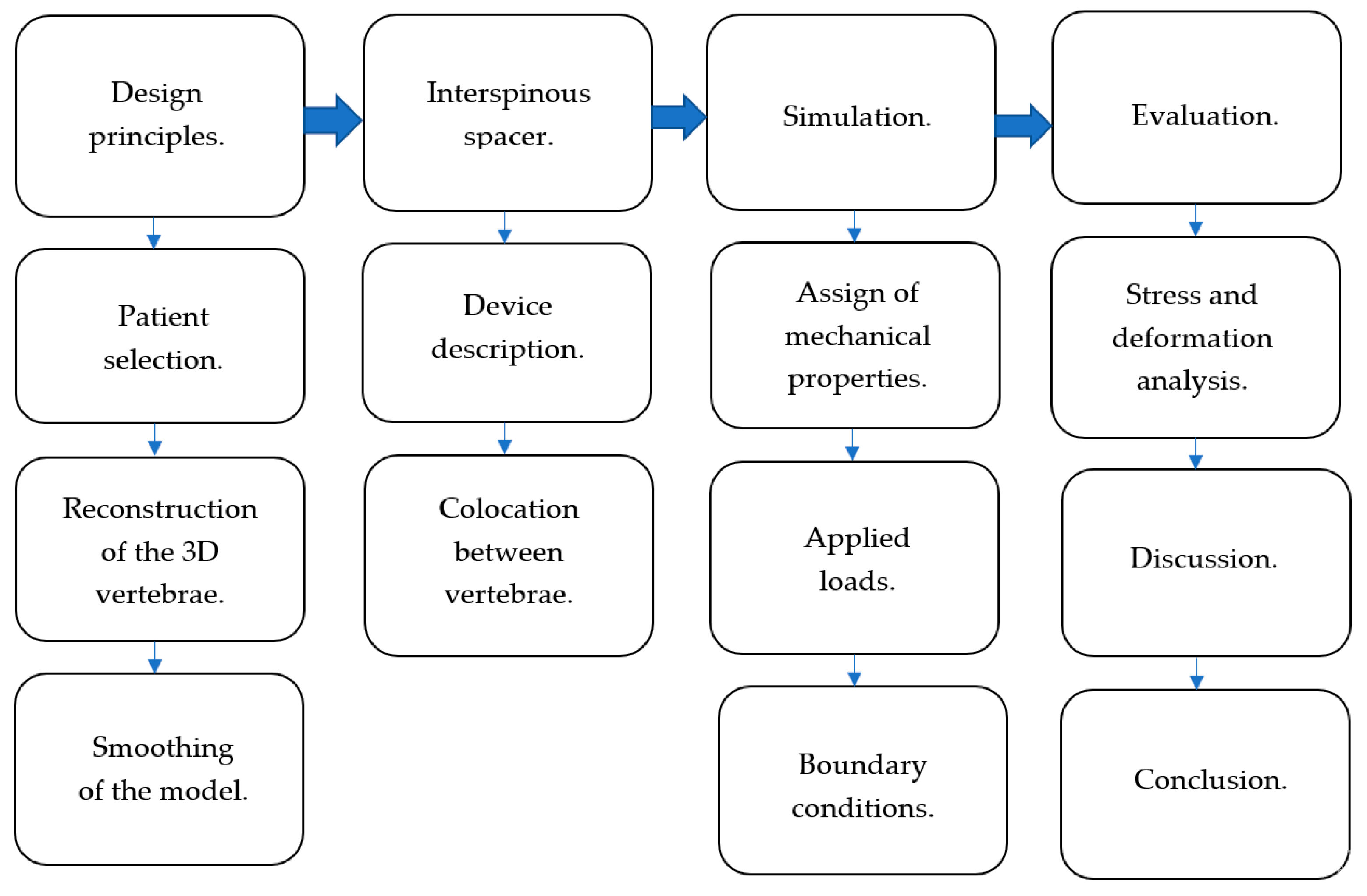
2. Materials and Methods

The experience of several surgeons and patented models and the satisfactory results of surgical operations establish the parameters shown in Figure 1 to carry out a methodology to apply the FEM to the ISP.
Many ISPs have been designed for clinical use [33]. Many studies have been reported as a treatment for SDD [34,35,36,37]. Different clinical studies are required to corroborate the correct functioning of the implants. Table 1 shows various clinical studies performed on the most commonly used ISPs. It should be mentioned that only DIAM and X-STOP spacers are recommended by the FDA of the United States of America [2].
The studies in Table 1 are related from a medical point of view because they relieve spinal stenosis. The differences between the ISPs are in the design and how they are fixed to the column. Our device is a new ISP design proposal. It tries to avoid the issues related to Table 1.
Table 2 summarizes the list of the most relevant patents registered, showing characteristics and how the prosthesis is placed.

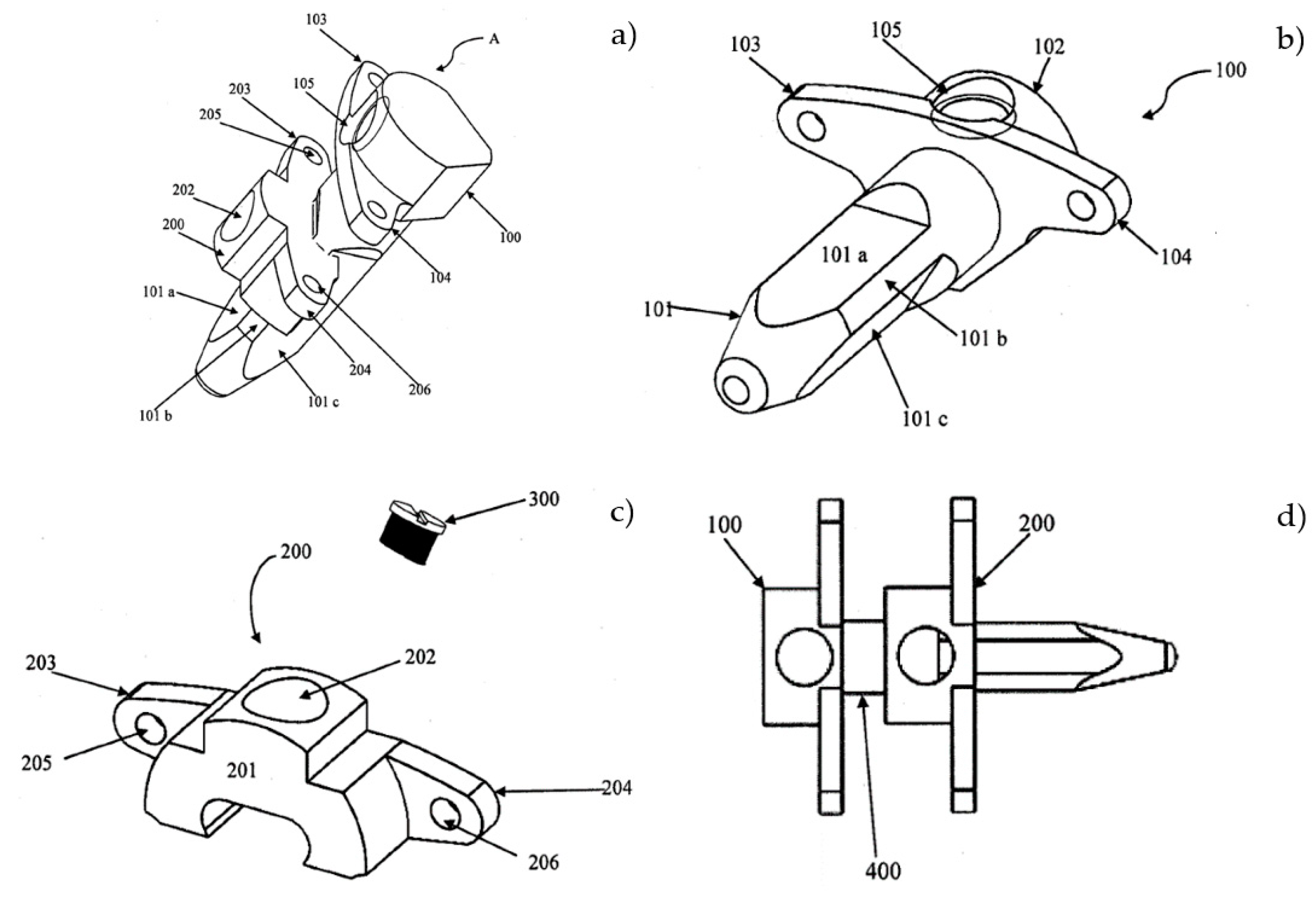
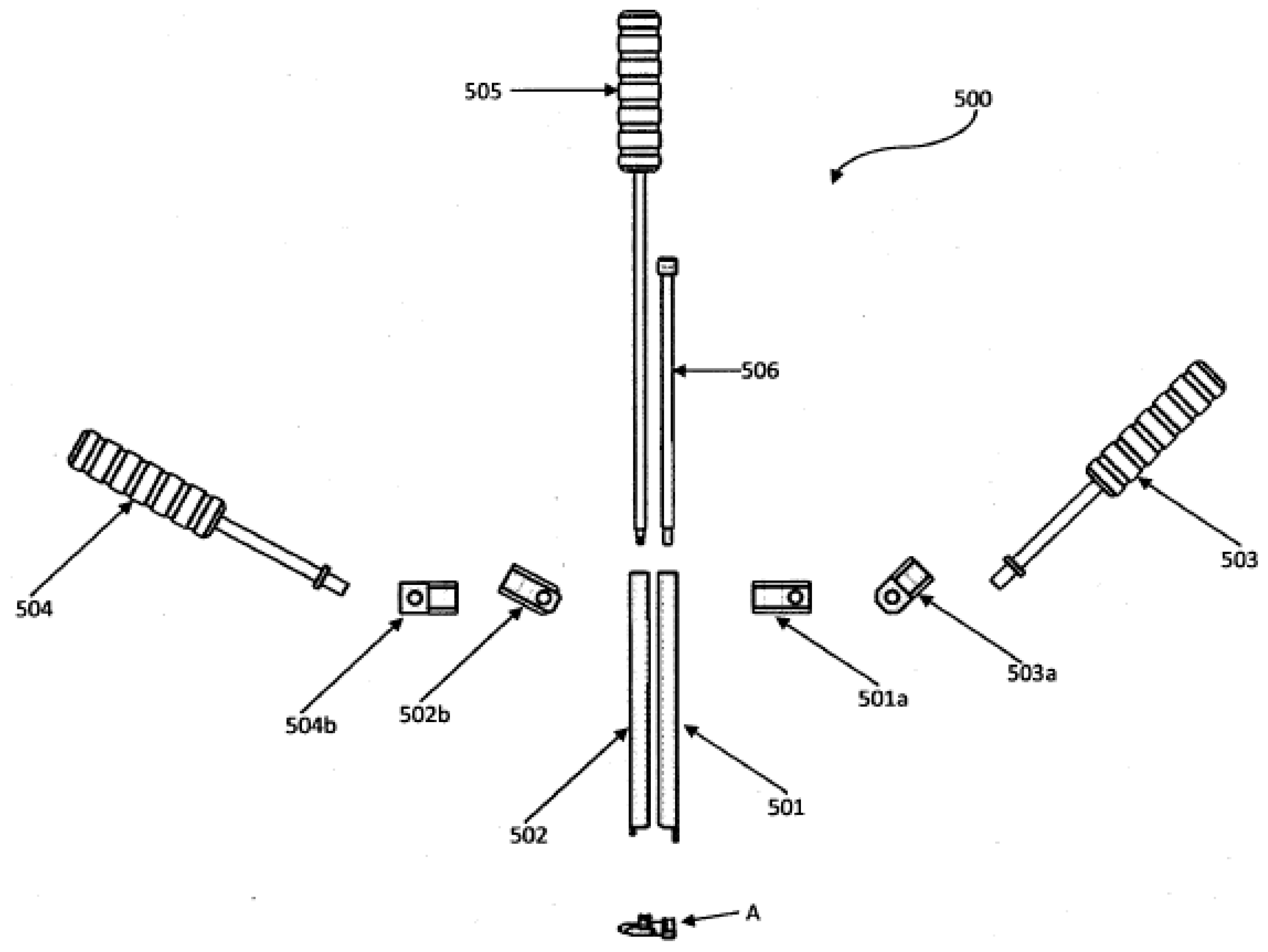
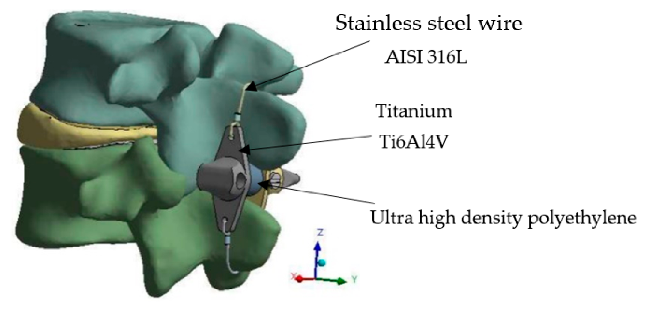
2.1. Device Description

The device has its uses in the biomedical field. It falls in the area of prostheses, more specifically in the area of surgical instruments, since it consists of a stabilizing device and an ISP. It is designed for patients with SDD that causes back and leg pain. The device contemplates the patient’s morphology regarding the space between the apophysis, thus avoiding the extension and contraction of the vertebral canal. It is made of a biocompatible material [46]. The information presented in Table 1 and Table 2 helps summarize the different ISPs. Still, none of them have a “T” geometry with a hexagonal body that prevents rotation and misalignment by itself, as well as a distractor clamp for placement. This prosthesis stabilizes the spine (A) with a distracting clamp (500) placed between the vertebrae. The extension and contraction of the vertebral canal are avoided for patients with spinal stenosis, either rigid or dynamic. The ISP (A) is divided into a first (100) and a second “T”-shaped spacer (200) (Figure 2a) for placement between the lower and upper apophysis adjacent to the vertebra.
Figure 2a,b show the first “T”-shaped spacer (100), whose hexagonal body (101) on each side has flat tracks (101a, 101b, 101c) and ends in a sharp point. It has a holding head at the upper end (102) to place it between the apophysis. The clamping head (102) has two flat supports (103 and 104) with a paraboloid shape as well as a hole (105) in the center of the clamping head (102) that allows positioning the first “T”-shaped spacer (100) between the vertebrae. The purpose is to support the spiny apophysis of the vertebrae.
Figure 2a,c show the second “T”-shaped spacer (200), which is shorter than the first “T”-shaped spacer (100). This is because it has a “C”-shaped body (201) to move along the flat tracks (101; 101b, 101c) of the hexagonal body (101) of the first “T”-shaped spacer (100) up to the extension or contraction distance, according to the geometry of the apophysis of the patient’s spine. A hole (202) is in the center of the “C” body-shaped (201) for the insertion of a locking screw (300) that fixes it to the first “T”-shaped spacer (100).
In turn, on the upper sides of the body (201) protrude two flat supports (203 and 204) to hold the apophysis. In addition, each flat support (203 and 204) has a hole (205 and 206) to strengthen the attachment of the second “T”-shaped spacer (200) with surgical wire; see Figure 2b. The locking screw (300) is preferably made of titanium; however, it can be manufactured with any biocompatible material.
A cylindrical tube (400) made of biocompatible material is placed around the hexagonal body (101). The first “T”-shaped spacer (100) ensures the contraction or extension distance between the first and second “T”-shaped spacers (100 and 200) shown in Figure 2d.
A distractor clamp (500) should be used to position the device (see Figure 3). Two parallel, hollow bars (501 and 502) constitute the distractor clamp. It is formed by two holding tools (503 and 504), each connected by a fastening system (503a and 504b) to a base link (501a and 502b). The holding tool has handles that allow the surgeon to position and manipulate the spinal stabilizer and ISP (A). To place the ISP, the surgeon must introduce a screwdriver (506) into the first bar (501) and screw the locking screw (300) into the hole (202) of the second T-shaped spacer (200). The locking screw must be fixed at the extension or contraction distance. Meanwhile, inside the second parallel bar (502) is a second screwdriver (505). It is inserted into the hole (105) of the first T-shaped spacer (100), allowing the surgeon to position it between the vertebrae. The screwdrivers (505 and 506) are inside the two parallel bars (501 and 502) and have free movement on the vertical axis. The handles of the holding tool (503 and 504) are preferably made of ultra-high-density polyurethane, and the distractor clamp (500) is preferably made of 316 L stainless steel.

2.2. General Conditions

The ISP analysis considered that a 3D model of the functional unit in the L3–L4 segment is required. The functional unit comprises the lumbar vertebrae L3, L4, the annulus fibrosus, and the nucleus pulposus. For the construction of the model, medical images were used that were obtained by CT. The images were generated by a Philips tomograph, with a resolution of 1 mm for each cut. Subsequently, the file (medical images) was exported in DICOM format. The software processed and created image models to generate the vertebrae. The program was instructed to perform 100 iterations to obtain better smoothing of the model. Finally, a solid model is created, which can be seen in Figure 4.
ISP was modeled using Solidworks. The model of the functional unit (vertebrae L3–L4) was assembled with the ISP by 1.2 mm diameter stainless steel wires. The wires held the spacer with the spinous apophyses (Figure 5).
The mesh was generated based on solid 186, a high-order element with quadratic displacement behavior. The generated mesh has 367,174 nodes and 213,107 elements. The numerical analysis considered a significant risk factor regarding the use of ISP in patients with a body mass index (BMI) greater than 40 kg/m2, which corresponds to grade III obesity, so its use is not recommended in patients with a higher BMI. For the maximum load, a Mexican patient of average height (1.64 m) with a mass of 108 kg (obesity grade II) generates a load of 706.3 N. The bone internal reaction was distributed over an area of 974 mm2, causing a pressure of 0.725 MPa, which was applied to the upper part of the L3 vertebra and the lower part of the L4 vertebra fixed at all degrees of freedom (Figure 6).
Vertebrae, like the intervertebral disc, are orthotropic, non-homogenous, and non-linear materials. For the simplification of the study, it is considered isotropic, homogeneous, linear, and continuous [46]. ISP deals with the same assumptions. Table 3 shows the mechanical properties of the materials [47,48,49]. The contact assumption for the simulation was considered “bonded”. In this contact, defined geometries act like one body. Bodies cannot move (slide or separate) and rotate between each other.

3. Results

3.1. Model Validation

The model’s validation was performed considering the behavior of the FEM model in relaxed standing without the ISP versus the loads and ROMs used by other researchers. In the literature, the forces employed in experiments and simulations vary from 220 N to 1200 N [32,50,51,52,53]. The displacements coincide with other research [54].
Jia-Yu Yin et al. [52] developed a FEM study with an ISP, and they applied static forces from 1200 to 720 N (axial force) and moments from 5.5 to 7.5 N-m, respectively. In this study, the applied axial force is 706.63 N. Also, it used transversal forces in the apophysis to generate moments for model validation. The range of the forces was from 49.05 to 147.15 N. The results of the comparison of the studies are summarized in Table 4.
The results obtained in vertebrae L3 and L4 show acceptable behavior compared to the previous study. Therefore, the model is considered suitable to simulate the behavior of the bone.

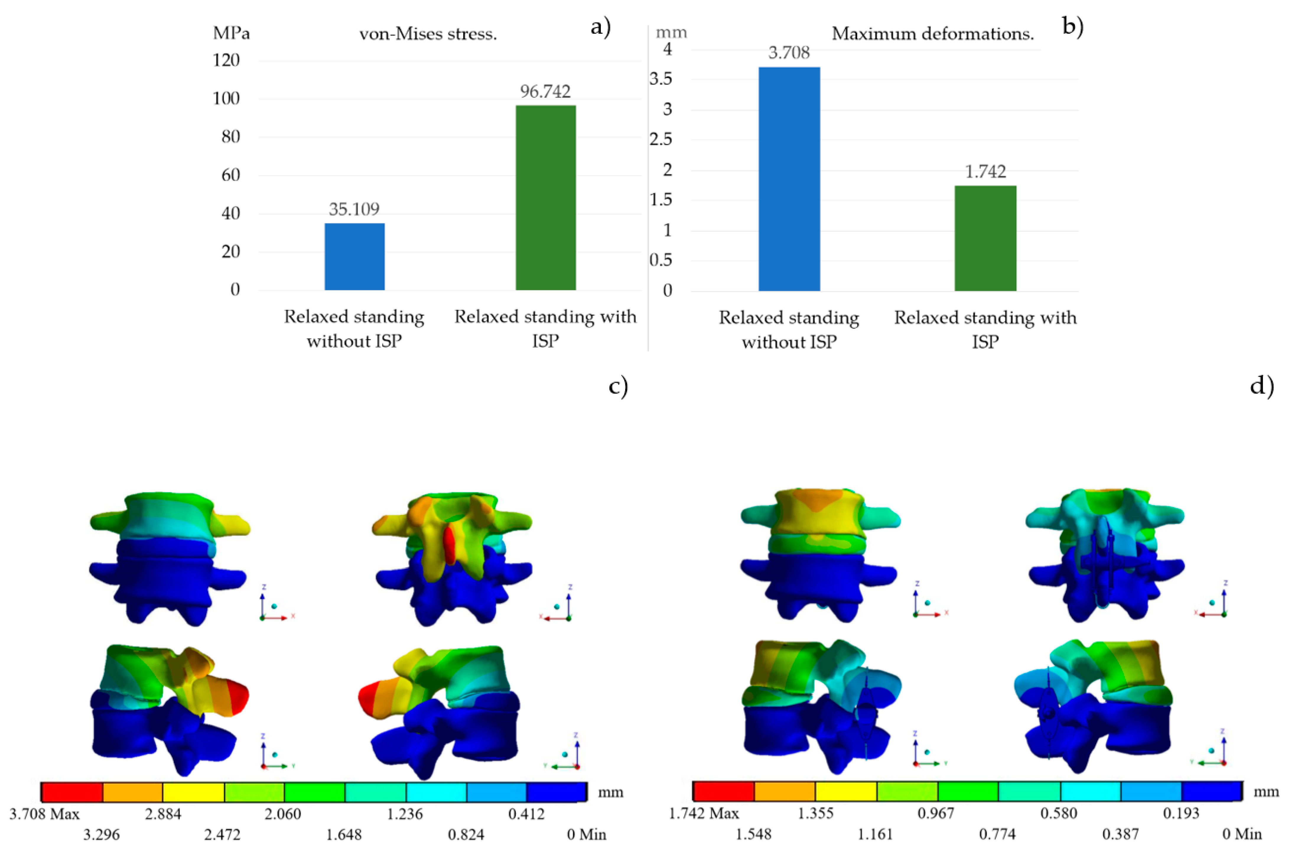
3.2. Relaxed Standing

Figure 7 shows the results from the relaxed standing simulation comparing the stresses and deformations when the ISP is used and when it is not. The cases presented a variation of 61.633 MPa, equivalent to a ratio of 2.7, while the deformation decreased by 53% when the prosthesis was used (ISP).

4. Discussion

Pablo Hernandez-Lucas et al. [11] state, “Interventions combining exercise therapy and health education seem to have a greater preventive effect on SDD than medical care”. These results may help healthcare professionals increase the effectiveness of their clinical interventions, but there is a possibility that surgery is inevitable. ISP is an alternative for pain relief.
This research shows the behavior of an interspinous spacer placed on the L3 and L4 vertebrae to decrease intervertebral disc compression. The FEM is used to analyze the behavior of the implant, assuming a critical case study related to a grade 2 BMI. This research does not consider vertebrae’s computational model of nerves, ligaments, muscles, or fluids that could increase the simulation’s success rate and decrease the incidence of overestimation of compressive load in the lumbar spine [55]. Lateral bending, rotation, and flexo-extension were done to validate the vertebrae´s biomodel. Those results are in agreement [51], as reported in Table 4. This research approximates results written by other authors, as described below.
The model without the ISP was compared against experimental and FEM data obtained by other researchers, giving favorable results. Figure 7 compares the stresses and deformations of the model with and without the ISP, showing that when the implant is used, the stress increases approximately at a ratio of 2.7 times. This is because the ISP creates an armor effect that stabilizes the vertebrae, which in turn helps to resist any abnormal joint motions during flexion, bending, and rotation. When simulated without the prosthesis, the maximum stiffness is in the cortical bone. When simulated without the prosthesis, the cortical bone’s stiffness is its maximum rigidity. When simulated with the ISP, the titanium’s stiffness is more significant than the bone’s. This results in an increase of 61.633 MPa. Figure 8 shows that the maximum stress field values are in the prosthesis, while the stress on the vertebrae decreases. Figure 7b shows that the deformation of the system is reduced by 1.966 mm (53%). This indicates that the prosthesis fulfills its function since the stress and deformations in the vertebrae are decreasing. Figure 7c,d show the reduction of the vertebral deformation distribution. This provides better stability for the spine.
Comparing the results with those of other researchers that have used the FEM to visualize the behavior of various ISP [32,50,51,52,53,54], it is concluded that the results are satisfactory since, in these studies, the maximum forces are generated in the prosthesis and the deformations are reduced. Therefore, the prostheses end up providing excellent stability to the spine.
The role of stainless-steel cables (Figure 2a) as a fixation system is significant. These are the reasons for the displacement reduction (53%). Also, collocation will not generate any trouble for the patient because it is minimally invasive. Therefore, the vertebrae end up having more stability.
An isotropic model was considered, and each element has a different stiffness. This is supported by the mechanical properties of the materials reported in Table 3. The isotropic assumption was made to simplify the bone structure. The ISP is made of metal and polyethylene. Those materials are considered isotropic. M. Dreischarf et al. [24] compared eight different lumbar spine models. Three models felt the cortical and cancellous bones as isotropic materials. That study confirms that by combining several distinct models, the median of individual numerical results can be used as an improved prediction to estimate the response of the lumbar spine. This is because the variation between the eight models does not differ. The assumption made in this article is related to the isotropic characteristic of the model, in agreement with the literature on the data.
The ISP developed is less invasive than the solution proposed by Robert Hudgins [38], Larry Khoo [39], Kyle Hayes [41], and Kamran Aflatoon [44]. The devices cited need to penetrate the apophysis or another part of the vertebrae for collocation. The ISP developed does not do that due to the fixation system implemented (stainless steel cables). Also, this system helps with its fixed collocation. It makes it easier to set up the device.
There are some similarities in the fixed position of the device developed by Harold Hess [41], James J. Yue [43], and Josef Gabelberger [45], but our ISP does not have so many components like the cited prosthesis, so the manufacturing process is easier and cheaper than the other ones.

5. Conclusions

This work shows how the ISP significantly reduces the forces and ranges of motion in the L3–L4 vertebrae, which can relieve pain in the lower back area. Gazzeri reported, “The ISP analyses increase the risk of fracture of the spiny process”. The prosthesis avoids this problem due to its geometry and materials implemented.
The ISP comprises a first and second T-shaped spacer supporting the spiny apophysis. It is designed to adapt to the morphological geometry of the vertebral patient. The second T-shaped spacer is fixed to the first spacer with a locking screw until the extension or contraction distance has been established. A cylinder is placed around the first spacer to ensure correct spacing between both spacers. Therefore, the device’s colocation avoids pain in the back and legs.
The benefits of using the ISP developed are discussed in the discussion section. Also, it compares the behavior when the ISP operates the fixation system and when it does not. Results suggest widely using the fixation system because stresses and displacements are reduced in the bone composition.

6. Patents

MX/u/2018/000355 named “DISPOSITIVO ESTABILIZADOR Y ESPACIADOR INTERES-PINOSO DE COLUMNA”.

Author Contributions

Conceptualisation, C.R.T.-S.M. and M.F.H.-O.; methodology, C.R.T.-S.M.; software, M.F.H.-O.; validation, C.R.T.-S.M. and G.M.U.-C.; formal analysis, E.A.A.-A.; investigation, J.C.P.-R.; resources, C.R.T.-S.M.; data curation, J.C.P.-R.; writing—original draft preparation, E.A.A.-A.; writing—review and editing, C.R.T.-S.M.; visualization, O.C.-R.; supervision, G.M.U.-C.; project administration, C.R.T.-S.M.; funding acquisition, C.R.T.-S.M. All authors have read and agreed to the published version of the manuscript.

Funding

The authors are thankful to the Consejo Nacional de Ciencia y Tecnología (CONAHCyT) and the Instituto Politécnico Nacional for the support received with projects 20231625 and 20231131, as well as the EDI grant, all from SIP/IPN.

Institutional Review Board Statement

Not applicable.

Informed Consent Statement

Not applicable.

Acknowledgments

The authors are thankful to the Instituto Politécnico Nacional and an EDI grant from SIP/IPN.

Conflicts of Interest

The authors declare no conflict of interest.

References

  1. James, S.L.; Abate, D.; Abate, K.H.; Abay, S.M.; Abbafati, C.; Abbasi, N.; Abbastabar, H.; Abd-Allah, F.; Abdela, J.; Abdelalim, A.; et al. Global, regional, and national incidence, prevalence, and years lived with disability for 354 diseases and injuries for 195 countries and territories, 1990–2017: A systematic analysis for the Global Burden of Disease Study 2017. Lancet 2018, 392, 1789–1858. [Google Scholar] [CrossRef]
  2. Francisco, M.; Ortega, H. Numerical Analysis of an Interspinous Spacer; National Polytechnic Institute UPIS ESIME Zacatenco: Ciudad de México, México, 2019. [Google Scholar]
  3. Neal, C. The assessment of knowledge and application of proper body mechanics in the workplace. Orthop. Nurs. 1997, 16, 66–67, 69. [Google Scholar] [CrossRef] [PubMed]
  4. Social Communication. In the IMSS, More than 300 Thousand Consultations for Low Back Pain in 2017. Available online: http://www.imss.gob.mx/prensa/archivo/201810/246 (accessed on 3 October 2018).
  5. McGill, S.M.; Hughson, R.L.; Parks, K. Changes in lumbar lordosis modify the role of the extensor muscles. Clin. Biomech. 2000, 15, 777–780. [Google Scholar] [CrossRef]
  6. Behennah, J.; Conway, R.; Fisher, J.; Osborne, N.; Steele, J. The relationship between balance performance, lumbar extension strength, trunk extension endurance, and pain in participants with chronic low back pain, and those without. Clin. Biomech. 2018, 53, 22–30. [Google Scholar] [CrossRef]
  7. Mork, R.; Falkenberg, H.K.; Fostervold, K.I.; Thorud, H.-M.S. Discomfort glare and psychological stress during computer work: Subjective responses and associations between neck pain and trapezius muscle blood flow. Int. Arch. Occup. Environ. Health 2019, 93, 29–42. [Google Scholar] [CrossRef] [PubMed]
  8. Zheng, C.-J.; Chen, J. Disc degeneration implies low back pain. Theor. Biol. Med Model. 2015, 12, 24. [Google Scholar] [CrossRef]
  9. Allegri, M.; Montella, S.; Salici, F.; Valente, A.; Marchesini, M.; Compagnone, C.; Baciarello, M.; Manferdini, M.E.; Fanelli, G. Mechanisms of low back pain: A guide for diagnosis and therapy. F1000Research 2016, 5, 1530. [Google Scholar] [CrossRef] [PubMed]
  10. Wilke, H.-J.; Rohlmann, F.; Neidlinger-Wilke, C.; Werner, K.; Claes, L.; Kettler, A. Validity and interobserver agreement of a new radiographic grading system for intervertebral disc degeneration: Part I. Lumbar spine. Eur. Spine J. 2006, 15, 720–730. [Google Scholar] [CrossRef] [PubMed]
  11. Hernandez-Lucas, P.; Leirós-Rodríguez, R.; Lopez-Barreiro, J.; García-Soidán, J.L. Is the combination of exercise therapy and health education more effective than usual medical care in the prevention of non-specific back pain? A systematic review with meta-analysis. Ann. Med. 2022, 54, 3106–3115. [Google Scholar] [CrossRef] [PubMed]
  12. Jecko, V.; Loit, M.-P.; Houston, D.; Champeaux-Depond, C. Functional Outcome after Spinal Meningioma Surgery. Asian Spine J. 2022, 16, 692–701. [Google Scholar] [CrossRef] [PubMed]
  13. Shao, X.; Liu, H.; Wu, J.; Qian, Z.; Qu, R.; Liu, T. A retrospective comparative study of postoperative sagittal balance in isthmic L5–S1 spondylolisthesis using single segment or two-segment pedicle screw fixation. BMC Musculoskelet. Disord. 2022, 23, 145. [Google Scholar] [CrossRef] [PubMed]
  14. Ko, S.; Jun, C.; Nam, J. Comparison of Fusion Rate and Functional Outcome Between Local Cancellous Bone Plus Demineralized Bone Matrix and Local Bone in 1-Level Posterior Lumbar Interbody Fusion. Clin. Spine Surg. A Spine Publ. 2022, 35, E621–E626. [Google Scholar] [CrossRef] [PubMed]
  15. Zhu, J.; Shen, H.; Cui, Y.; Fogel, G.R.; Liao, Z.; Liu, W. Biomechanical Evaluation of Transforaminal Lumbar Interbody Fusion with Coflex-F and Pedicle Screw Fixation: Finite Element Analysis of Static and Vibration Conditions. Orthop. Surg. 2022, 14, 2339–2349. [Google Scholar] [CrossRef] [PubMed]
  16. Poetscher, A.W.; Gentil, A.F.; Ferretti, M.; Lenza, M. Interspinous process devices for treatment of degenerative lumbar spine stenosis: A systematic review and meta-analysis. PLoS ONE 2018, 13, e0199623. [Google Scholar] [CrossRef] [PubMed]
  17. Puzzilli, F.; Gazzeri, R.; Galarza, M.; Neroni, M.; Panagiotopoulos, K.; Bolognini, A.; Callovini, G.; Agrillo, U.; Alfieri, A. Interspinous spacer decompression (X-STOP) for lumbar spinal stenosis and degenerative disk disease: A multicenter study with a minimum 3-year follow-up. Clin. Neurol. Neurosurg. 2014, 124, 166–174. [Google Scholar] [CrossRef] [PubMed]
  18. Liu, Z.; Zhang, S.; Li, J.; Tang, H. Biomechanical comparison of different interspinous process devices in the treatment of lumbar spinal stenosis: A finite element analysis. BMC Musculoskelet. Disord. 2022, 23, 585. [Google Scholar] [CrossRef]
  19. Erbulut, D.U.; Zafarparandeh, I.; Hassan, C.R.; Lazoglu, I.; Ozer, A.F. Determination of the biomechanical effect of an interspinous process device on implanted and adjacent lumbar spinal segments using a hybrid testing protocol: A finite-element study. J. Neurosurg. Spine 2015, 23, 200–208. [Google Scholar] [CrossRef] [PubMed]
  20. Hsieh, C.-T.; Chen, Y.-H.; Huang, K.-C.; Ko, P.-C.; Sun, J.-M. Preliminary report on value of Wallis interspinous device for back pain following microdiscectomy. Formos. J. Surg. 2022, 55, 163–170. [Google Scholar] [CrossRef]
  21. Arriba, M.P.; Maestre, C.; Martín-Gorroño, F.; Plasencia, P. Analysis of Long-Term Results of Lumbar Discectomy With and Without an Interspinous Device. Int. J. Spine Surg. 2022, 16, 681–689. [Google Scholar] [CrossRef] [PubMed]
  22. Wang, B.; Ke, W.; Hua, W.; Lu, S.; Zeng, X.; Yang, C. Biomechanical evaluation of anterior and posterior lumbar surgical approaches on the adjacent segment: A finite element analysis. Comput. Methods Biomech. Biomed. Eng. 2020, 23, 1109–1116. [Google Scholar] [CrossRef] [PubMed]
  23. Zhou, Z.; Jin, X.; Wang, C.; Wang, L. Wallis interspinous device versus discectomy for lumbar disc herniation. Orthopade 2018, 48, 165–169. [Google Scholar] [CrossRef] [PubMed]
  24. Dreischarf, M.; Zander, T.; Shirazi-Adl, A.; Puttlitz, C.; Adam, C.; Chen, C.; Goel, V.; Kiapour, A.; Kim, Y.; Labus, K.; et al. Comparison of eight published static finite element models of the intact lumbar spine: Predictive power of models improves when combined together. J. Biomech. 2014, 47, 1757–1766. [Google Scholar] [CrossRef] [PubMed]
  25. Schmidt, H.; Galbusera, F.; Rohlmann, A.; Shirazi-Adl, A. What have we learned from finite element model studies of lumbar intervertebral discs in the past four decades? J. Biomech. 2013, 46, 2342–2355. [Google Scholar] [CrossRef] [PubMed]
  26. Rohlmann, A.; Lauterborn, S.; Dreischarf, M.; Schmidt, H.; Putzier, M.; Strube, P.; Zander, T. Parameters influencing the outcome after total disc replacement at the lumbosacral junction. Part 1: Misalignment of the vertebrae adjacent to a total disc replacement affects the facet joint and facet capsule forces in a probabilistic finite element analysis. Eur. Spine J. 2013, 22, 2271–2278. [Google Scholar] [CrossRef]
  27. Borrelli, S.; Putame, G.; Pascoletti, G.; Terzini, M.; Zanetti, E.M. In Silico Meta-Analysis of Boundary Conditions for Experimental Tests on the Lumbar Spine. Ann. Biomed. Eng. 2022, 50, 1243–1254. [Google Scholar] [CrossRef]
  28. Guldeniz, O.; Yesil, O.B.; Okyar, F. Yeditepe spine mesh: Finite element modeling and validation of a parametric CAD model of lumbar spine. Med. Eng. Phys. 2022, 110, 103911. [Google Scholar] [CrossRef]
  29. Sanjay, D.; Bhardwaj, J.S.; Kumar, N.; Chanda, S. Expandable pedicle screw may have better fixation than normal pedicle screw: Preclinical investigation on instrumented L4-L5 vertebrae based on various physiological movements. Med. Biol. Eng. Comput. 2022, 60, 2501–2519. [Google Scholar] [CrossRef]
  30. Little, J.; Adam, C. Geometric sensitivity of patient-specific finite element models of the spine to variability in user-selected anatomical landmarks. Comput. Methods Biomech. Biomed. Eng. 2013, 18, 676–688. [Google Scholar] [CrossRef]
  31. Gazzeri, R.; Galarza, M.; Neroni, M.; Fiore, C.; Faiola, A.; Puzzilli, F.; Callovini, G.; Alfieri, A. Failure rates and complications of interspinous process decompression devices: A European multicenter study. Neurosurg. Focus 2015, 39, E14. [Google Scholar] [CrossRef]
  32. Chen, H.-C.; Wu, J.-L.; Huang, S.-C.; Zhong, Z.-C.; Chiu, S.-L.; Lai, Y.-S.; Cheng, C.-K. Biomechanical evaluation of a novel pedicle screw-based interspinous spacer: A finite element analysis. Med. Eng. Phys. 2017, 46, 27–32. [Google Scholar] [CrossRef]
  33. Hu, Y.-X.; Wang, Y.-F.; Han, J.; Liu, S.-M.; Wang, H. Percutaneously placed lumbar interspinous stabilization devices—A review of current clinical research. Eur. Rev. Med. Pharmacol. Sci. 2022, 26, 4244–4251. [Google Scholar] [PubMed]
  34. Nandakumar, A.; Clark, N.A.; Smith, F.W.; Wardlaw, D. Two-Year Results of X-Stop Interspinous Implant for the Treatment of Lumbar Spinal Stenosis. J. Spinal Disord. Tech. 2013, 26, 1–7. [Google Scholar] [CrossRef]
  35. Cho, Y.J.; Park, J.-B.; Chang, D.-G.; Kim, H.J. 15-year survivorship analysis of an interspinous device in surgery for single-level lumbar disc herniation. BMC Musculoskelet. Disord. 2021, 22, 1030. [Google Scholar] [CrossRef] [PubMed]
  36. Lewandrowski, K.-U.; Abraham, I.; León, J.F.R.; Cantú-Leal, R.; Longoria, R.C.; Sánchez, J.A.S.; Yeung, A. A Differential Clinical Benefit Examination of Full Lumbar Endoscopy vs. Interspinous Process Spacers in the Treatment of Spinal Stenosis: An Effect Size Meta-Analysis of Clinical Outcomes. Int. J. Spine Surg. 2022, 16, 102–123. [Google Scholar] [CrossRef] [PubMed]
  37. Pavan, L.J.; Dalili, D.; De Vivo, A.E.; Hamel-Senecal, A.; Torre, F.; Rudel, A.; Manfré, L.; Amoretti, N. Clinical and radiological outcomes following insertion of a novel removable percutaneous interspinous process spacer: An initial experience. Neuroradiology 2022, 64, 1887–1895. [Google Scholar] [CrossRef] [PubMed]
  38. Robert, H.D.H.; Hudgins, G. In-Situ Curable Interspinous Process Spacer. US 2009/0118833 A1, 12 May 2009. [Google Scholar]
  39. Khoo, L. Percutaneous Interspinous Process Device And Method. US 8070779 B2, 6 December 2011. [Google Scholar]
  40. Hess, H. Interspinous Process Implants Having Deployable Engagement Arms. US 8142479 B2, 27 March 2012. [Google Scholar]
  41. Altarac, M.; Hayes, S.K.; Reglos, J.C.; Gutierrez, R.; Flaherty, J. System and Methods for Posterior Dynamic Stabilization of the Spine. US 2007/0219556A1, 20 September 2007. [Google Scholar]
  42. James, J.A.C.G.G.; Yue, J. Conical Interspinousapparatus and a Method of Performing Interspnous Distraction. US 8192466 B2, 5 June 2012. [Google Scholar]
  43. Felix Aschmann, B.B.D.C. Spinous Process Fixator. US 9168073 B2, 27 October 2015. [Google Scholar]
  44. Aflatoon, K. Dynamic Inter-Spinous Process Spacer. US 9204907 B2, 8 December 2015. [Google Scholar]
  45. Gabelberger, J. Expandable Interspinous Process Spacer Implant. US 9402732 B2, 2 August 2016. [Google Scholar]
  46. Hernández, A.F.; Cañizo, R.G.R.; Huerta, O.S.; Cruz, E.A.M.; Pineda, J.M.S.; Hernández, E.P. Aplicación de Metodología de Modelado 3D Utilizando Tomografías Computarizadas Para su Análisis Numérico; Revista Facultad de Ingeniería Universidad de Antioquia: Medellín, Colombia, 2014; pp. 116–126. [Google Scholar]
  47. Wang, W.; Zhou, C.; Guo, R.; Cha, T.; Li, G. Prediction of biomechanical responses of human lumbar discs - a stochastic finite element model analysis. Comput. Methods Biomech. Biomed. Eng. 2021, 24, 1730–1741. [Google Scholar] [CrossRef]
  48. Guo, L.-X.; Zhang, C. Development and Validation of a Whole Human Body Finite Element Model with Detailed Lumbar Spine. World Neurosurg. 2022, 163, e579–e592. [Google Scholar] [CrossRef] [PubMed]
  49. Fang, J.; Cao, J.; Zhang, J.; Rong, Q.; Zhou, D. Response Analysis of Lumbar Vertebra Model under Axial Impact Loading. In IUTAM Symposium on Impact Biomechanics: From Fundamental Insights to Applications; Springer: Berlin/Heidelberg, Germany, 2005; pp. 111–118. [Google Scholar] [CrossRef]
  50. Heo, M.; Yun, J.; Kim, H.; Lee, S.-S.; Park, S. Optimization of a lumbar interspinous fixation device for the lumbar spine with degenerative disc disease. PLoS ONE 2022, 17, e0265926. [Google Scholar] [CrossRef] [PubMed]
  51. Song, C.; Li, X.-F.; Liu, Z.-D.; Zhong, G.-B. Biomechanical assessment of a novel L4/5 level interspinous im-plant using three dimensional finite element analysis. Eur. Rev. Med. Pharmacol. Sci. 2014, 18, 86–94. [Google Scholar] [PubMed]
  52. Yin, J.-Y.; Guo, L.-X. Biomechanical analysis of lumbar spine with interbody fusion surgery and U-shaped lumbar interspinous spacers. Comput. Methods Biomech. Biomed. Eng. 2020, 24, 788–798. [Google Scholar] [CrossRef] [PubMed]
  53. Zhao, G.; Wang, X.; Liu, T.; Dong, L. Biomechanical analysis of a customized lumbar interspinous spacer based on transfacetopedicular screw fixation: A finite element study. Med Eng. Phys. 2022, 107, 103850. [Google Scholar] [CrossRef] [PubMed]
  54. Wong, C.-E.; Hu, H.-T.; Kao, L.-H.; Liu, C.-J.; Chen, K.-C.; Huang, K.-Y. Biomechanical feasibility of semi-rigid stabilization and semi-rigid lumbar interbody fusion: A finite element study. BMC Musculoskelet. Disord. 2022, 23, 10. [Google Scholar] [CrossRef] [PubMed]
  55. Wang, K.; Deng, Z.; Chen, X.; Shao, J.; Qiu, L.; Jiang, C.; Niu, W. The Role of Multifidus in the Biomechanics of Lumbar Spine: A Musculoskeletal Modeling Study. Bioengineering 2023, 10, 67. [Google Scholar] [CrossRef] [PubMed]
Figure 1. Diagram of the interspinous spacer analysis method.
Prosthesis 05 00065 g001
Figure 2. Interspinous spacer design. “(a)” Perspective view of the stabilizer and interspinous spacer. “(b)” 3D view of the first “T”-shaped spacer. “(c)” Perspective view of the second “T”-shaped spacer and locking screw. “(d)” Top view of the spinal stabilizer and interspinous spacer.
Prosthesis 05 00065 g002
Figure 3. Distractor clamp exploded view for the placement of the interspinous spacer.
Prosthesis 05 00065 g003
Figure 4. Sectional view of lumbar vertebrae L3, L4.
Prosthesis 05 00065 g004
Figure 5. Lumbar vertebrae L3, L4 reconstruction with an interspinous spacer.
Prosthesis 05 00065 g005
Figure 6. Boundary conditions. “(a)” Applied pressure. “(b)” Restriction of movement.
Prosthesis 05 00065 g006
Figure 7. Simulation results of relaxed standing with and without an interspinous spacer: “(a)” von Mises stress and “(b)” maximum deformations. “(c)” Deformation distribution simulation without an interspinous spacer. “(d)” Deformation distribution simulation with an interspinous spacer.
Prosthesis 05 00065 g007
Figure 8. von Mises stress “(a)” without an interspinous spacer. Red circles show the bone´s stress distribution and “(b)” with an interspinous spacer. Red circles remarks that the stresses has been decrease.
Prosthesis 05 00065 g008
Table 1. Interspinous spacer clinical studies.
ISPPatientsComplications Related to
Device
Reduction of
Symptoms
Wallis130Migration1NA
Incorrect placement of the deviceNA
Spinous process fracture0
Increased pain1
U209Migration1157/209
(75%)
Implant failure2
Spinous process fracture0
Increased painNA
DIAM1756Infection101505/1756
(85.7%)
Spinous process fracture10
Increased pain70
X-STOP201Migration2139/201
(69%)
Spinous process fracture13
Increased pain13
Incorrect placement of the deviceNA
Superion190MigrationNA123/190
(64.7%)
Spinous process fracture23
Increased pain8
Incorrect placement of the deviceNA
NA—not available.
Table 2. Patents registered from 2009 to 2018.
NameApproachCharacteristics
In Situ Curable ISP [38]Posterolateral percutaneous approachThe device is expandable, so its placement is compact. Once placed, it expands to the desired size by injecting fluid through a catheter.
Percutaneous Interspinous Process Device and Method [39]Posterolateral percutaneous approachIt has two lateral sections and a central unit. The lateral sections have a dentate contact area to obtain greater adherence to the spiny apophysis. The main section is joined to one of the lateral sections, with an anchor section at the end to join the other lateral area at the time of implantation.
Interspinous Process Implants with Deployable Engagement Arms [40]Posterolateral percutaneous approachThe body part can be partially threaded and have a smooth surface. The body part includes an inner cavity. It comprises deployable coupling members adapted and configured to move simultaneously through an actuating mechanism between a folded and retracted position within the internal cavity. In addition, each coupling arm may include a distal hook portion with teeth for coupling to the spinal process.
System and Methods for Posterior Dynamic Stabilization of the Spine [41]Posterolateral percutaneous approachIt has a main body with a cross-sectional size and shape that allows implantation between adjacent spiny apophyses. It has two pairs of movable arms between a folded and unfolded state. The individual extension arms can have any angle of curvature to facilitate the coupling of multiple spacers. In addition, it may include an element that allows them to be interconnected or joined in a fixed or dynamic manner.
Conical Interspinous Apparatus and a Method of Performing Interspinous Distraction [42]Posterolateral approachA conical screw ISP apparatus must have an insertion controller, a pair of deployable proximal wings, and a pair of deployable distal wings.
Spinous Process Fixator [43]Subsequent approachThe device has two auxiliary toothed side plates in the clamping mechanism. In addition, the spacer body can include a channel sized and configured to receive the expansion locking mechanism.
Dynamic Inter-Spinous Process Spacer [44]Posterolateral percutaneous approachThe device has two anchors and two retractable adjustment members (upper and lower). In addition, it has an internal mechanism for adjusting the retractable members.
Expandable Interspinous Process Spacer Implant [45]Posterolateral approachThe implant includes an upper casing, a lower casing, and a folding mechanism. The outer surfaces are configured to hook into the apophysis.
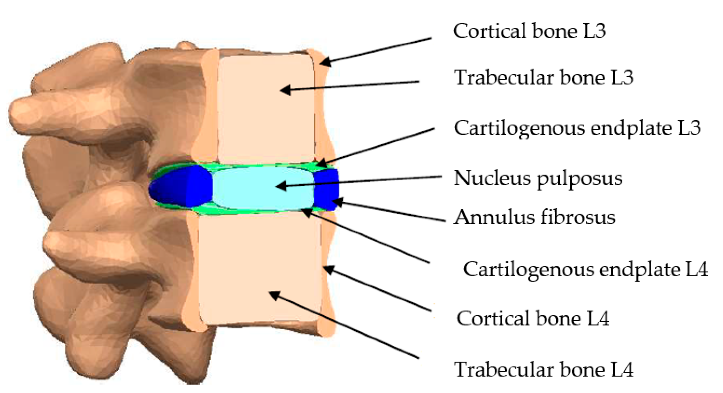
Table 3. Mechanical properties of the L3-L4 lumbar segment and interspinous spacer.
MaterialYoung’s Modulus (MPa)Density (kg/m3)Poisson’s Ratio
Cortical bone12,00019000.3
Trabecular bone1007000.2
Annulus fibrosus4.210650.45
Nucleus pulposus110000.4999
Cartilogenous endplates500---0.4
Ti6Al4V 113,80044200.342
Ultra high-density polyethylene11009500.42
Stainless steel
AISI 316 L
200,00077500.3
Table 4. Finite element’s result for static validation in vertebrae L3–L4.
StudyAxial Force (N)Moment or Force Intervertebral
Rotation (Degrees)
Reference
Bending movement11758 N-m 8 Jia-Yu Yin et al. [52]
Lateral bending7006 N-m 7
Axial rotations7204 N-m 2
Bending movement706.63 147.15 N 11.5Current study
Lateral bending706.63 83.3 N 8
Axial rotations706.63 49.05 N 2
Disclaimer/Publisher’s Note: The statements, opinions and data contained in all publications are solely those of the individual author(s) and contributor(s) and not of MDPI and/or the editor(s). MDPI and/or the editor(s) disclaim responsibility for any injury to people or property resulting from any ideas, methods, instructions or products referred to in the content.

