1. Introduction
Greenhouses are specially designed to provide suitable conditions which favor growth and production of plants annually. This is achieved through their unique structural characteristics which enable them to carry out their specified functions. For a greenhouse to be termed as well-designed, it must satisfy key objectives such as low construction and operation cost, efficient mechanical properties, efficient ventilation systems, low heat consumption, and allowance of high light transmittance.
Most existing greenhouses may be approved as inadequate in terms of resisting the design forces according to EN 13031 [
1] and Eurocodes [
2,
3,
4,
5] due to the fact that most of them are imported by European farmers from different countries such as Italy, The Netherlands, and Spain whose climatic and structural requirements are a little different from those of European Union (EU) countries [
6]. In other cases, the cultivators construct them on their own greenhouses. For all commercial greenhouses, the major problem is that the climate and terrain settings have significant differences amongst countries (which are also evident in different areas of the same country due to the rural geographical diversity); hence, it is quite unlikely that a greenhouse which was designed to be used in a different country is acceptable for use in different regions under the mentioned standards which govern the installation and application of greenhouses in different regions. Thus, local engineers have to make changes to the structural system to adapt to the particular local geographical environment.
Previous studies by Kim et al. [
7] and Vázquez et al. [
8] showed that the design of greenhouse steel structures has several deficiencies. Kim et al. [
7] discussed the different wind loads that are predicted based on different design codes worldwide, as well as the differences, uncertainties, and their effect on the safety of vaulted and pitched roof greenhouses. Vázquez et al. [
8] investigated the performance of typical cold-formed connections for a specific greenhouse and found that the design of the joints was inefficient.
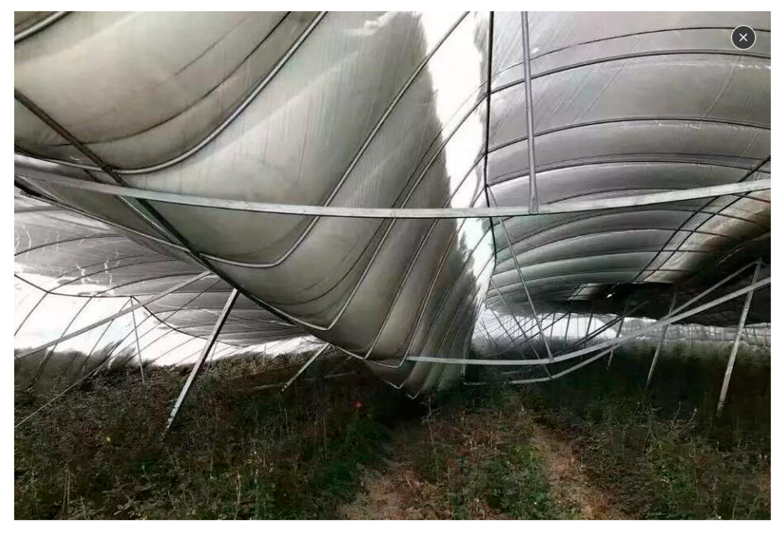
This study combines wind and snow loads according to European standard [
1,
2,
3] provisions, rendering the governing load combination [
4] for the ultimate limit state (ULS) design of steel structures [
5], which may lead to collapse (
Figure 1). This paper also focuses on strengthening techniques such as capacity and safety improvement methods due to poor initial design or the adoption of design standards from different regions.
Traditionally, many greenhouse structures experience natural disasters and various types of collapses occur, which usually do not involve loss of human life but significant loss of money and wealth. Thus, to protect them from collapse, appropriate repair and retrofitting techniques are in need, but there is scattered knowledge to date. This paper summarizes various core methods of repairing and retrofitting of such lightweight steel structures according to the code requirements. The assessment and retrofitting of two types of existing greenhouses are also presented as case studies.
2. Typical Structural System of European Steel Greenhouses
Greenhouses can be classified into two main categories based on their structural set-up: the standardized steel structures which are designed based on the national and international standards, and the low-cost greenhouses designed locally by farmers where the frames of the greenhouse are mainly wood. Different materials with different structural requirements are used to cover the standardized steel structures, which make each system unique. For example, the use of glass panels as a covering material requires a compact network of the main structure to make the roof, since glass panels are small and heavy, whereas their ability to withstand significant displacements and deflections of the supporting system is limited. Alternatively, flexible plastic films or other similar materials [
10] combined with lightweight steel structures can be designed to give different geometric types of covering materials. The geometry of a greenhouse affects both the structure and the micro-environment. There are two main forms of geometry in use and they include single and multi-span greenhouses. Greenhouses with single-span geometry have duo-pitch or vaulted roofs, while those with a multi-span geometry have vaulted or planar pitched roofs [
6].
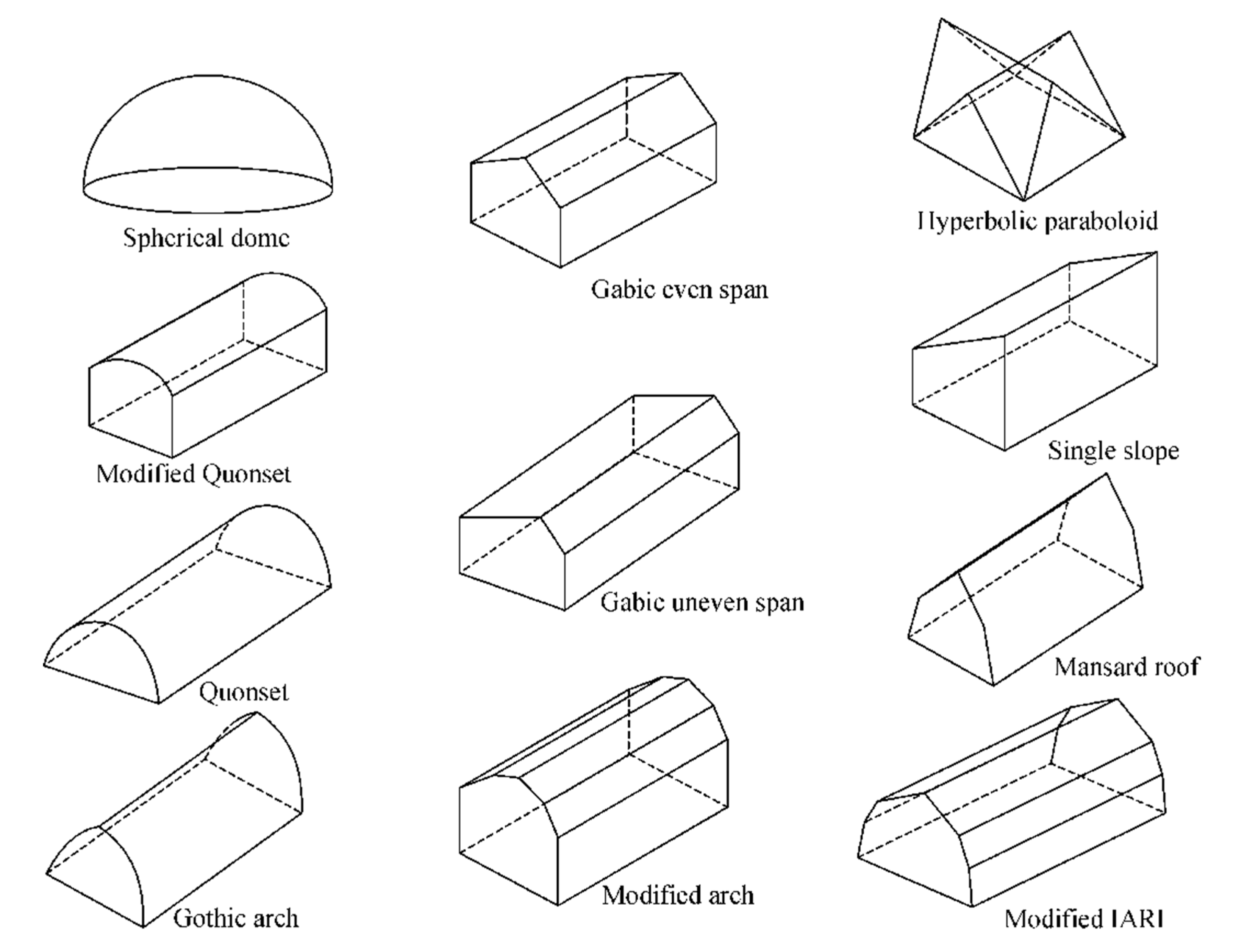
The structural layout of greenhouses consists of typical frames with different kinds of shapes. The most common shapes of the frames are Gabic even and uneven spans, mansard roof, Gothic arch, modified Quonset, Quonset, parabolic/hyperbolic, spherical dome, modified arch, and modified IARI, as indicated in
Figure 2.
Typical frames are formed by columns, main beams or trusses, purlins, vertical bracings, roof bracings, and gutters. The structural framing is most usually made of steel or aluminum. Smaller greenhouses constructed by farmers are sometimes made of wood. Moreover, another major classification parameter for greenhouses is the type of cladding. Typical coverings are made of glass, plastic film, PVC, or polyethylene [
11].
Greenhouses are also classified based on the expected life of the design. The life span of the cladding may differ from the design working life of the structural system. The minimum values of the design working life are given in EN 13031 [
1] and presented in
Table 1.
3. Greenhouse Structural Assessment Methodology
3.1. Collection of Data and Design Objectives
The primary aim of this paper is to lay out a methodology of structural assessment and retrofitting of existing greenhouses to resist design forces according to national codes.
The first step of the assessment study is to inspect the existing greenhouse and collect key signs such as frame damage, presence of corrosion, structural modification carried out during the life of the greenhouse without professional technical review, the level of deflections, signs of foundation settlements, damages to cladding, and added load or rig without the required professional structure review [
8].
When deciding to make any structural modifications on the greenhouse either to strengthen the structure or to modify an existing element, several objectives are considered during the process. These objectives include the following:
The information regarding the existing structural condition is sought first to understand the technical requirements.
The hidden structures which are costly or difficult to remove and may be obstructed by the service systems.
Undisrupted renovation works on the structure due to the need to continue greenhouse operations.
The true cost of retrofitting depends on a number of objectives since the non-structural costs often exceed the structural costs. The true costs depend on the number of works at different locations instead of the overall amount of work performed in each location, something which also determines decision analysis and the design of the structure [
12].
3.2. Actions on Greenhouses
Actions are defined according to EN 13031 [
1] and Eurocodes [
2,
3,
4,
5].
Permanent actions Gk1 are actions due to the non-structural elements and the structural self-weight. These do not include the installations, regardless of their presence.
Permanently present installation Gk2 actions are actions that result from equipment that is permanently installed such as that for ventilation, irrigation, shading, lighting, cooling, and heating.
Wind actions Qk1 and
snow actions Qk2 are calculated according to EN1991-1-4 [
4] and EN1991-1-3 [
3], taking into account the relative probability factor, the location, and the shape of the structure.
Crop actions Qk3 are actions due to crops and plants hanging or supported by the structure.
Concentrated vertical action Qk4 arises from maintenance and repair operations.
Incidentally present installation actions Qk5 are actions of variable magnitude due to mobile equipment such as gantries running on rails supported by the structure, and cleaning equipment running along the roof, including service personnel.
Thermal actions Qk6 are actions due to climatic and operational temperature differences and changes.
As the greenhouses have limited mass, the earthquake loading might not be of critical design importance when the greenhouse is built in a seismic area. In contrast, wind and snow load combinations are usually critical as they combine large horizontal loads due to wind with large vertical loads due to snow.
3.3. Structural Calculations
The structural behavior of the greenhouse is reflected in the calculations through the assumptions made and the general calculation model. This is done with ultimate accuracy which reflects the expected bearings, joints, members, and cross-sectional behaviors. If the deformed geometry (second-order) effects increase the effects of actions or have a significant effect, they are considered in the calculations. In particular, the requirements to be satisfied for each method of analysis are presented in
Table 2 as per EN 13031 [
1].
3.4. Design Checks
The design for serviceability and the ultimate limit states are performed in accordance with the applicable sections of EN 1992 through EN 1999 and their National Application Documents, depending on the materials and systems that are used. For steel structures, EN 1993 should be used. Greenhouses whose design actions lead frame displacement leading to limitation of the cladding system are named as type A; otherwise, they are named as type B according to EN 13031 [
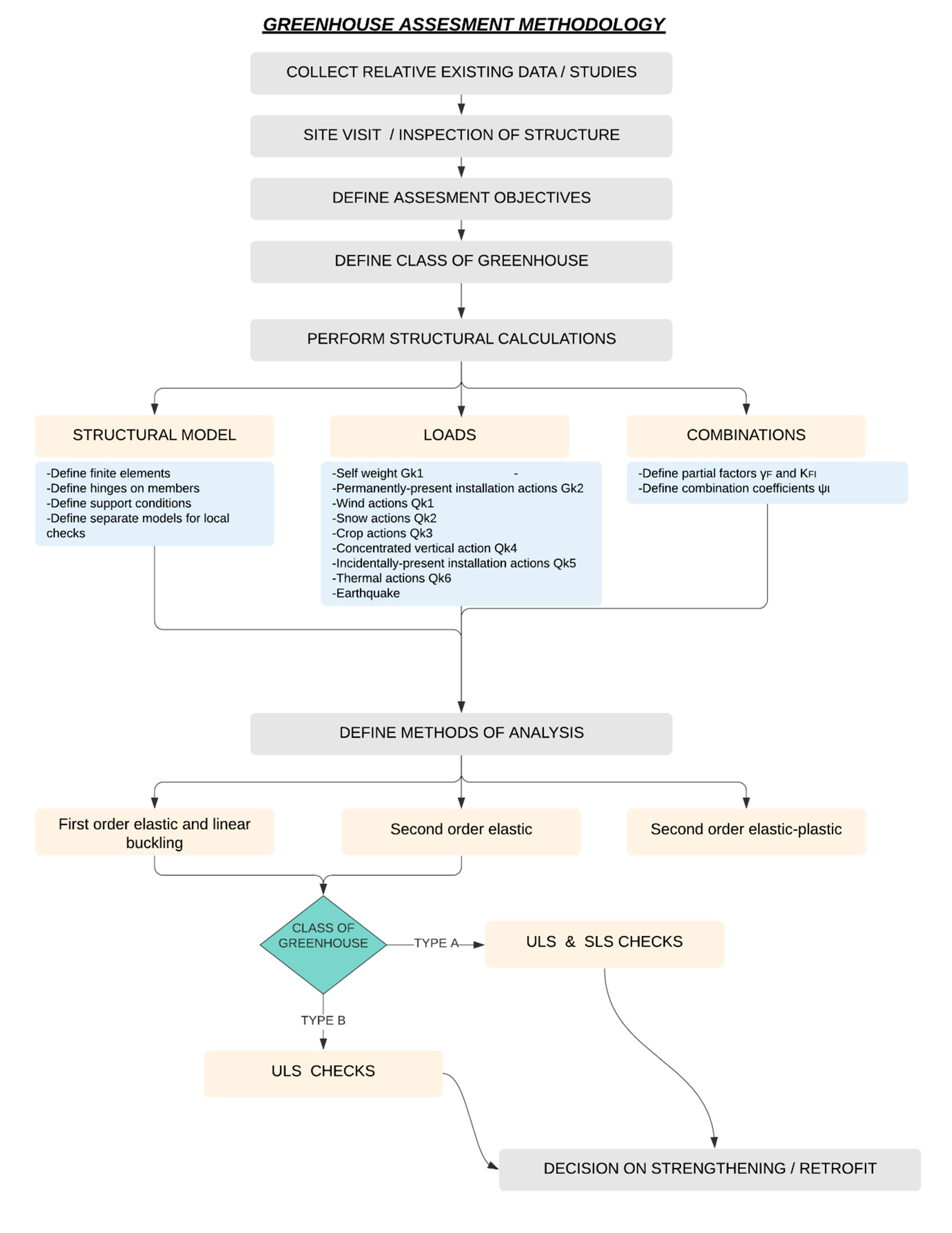
1]. Type A greenhouses are designed based on ULS and serviceability limit states (SLS). For type B greenhouses, only ULS is considered during the design. Displacements and deflections (SLS) should be checked at the gutter level at the column connection points with foundations. A typical flowchart of methodology assessment is indicated in
Figure 3.
4. Typical Strengthening Techniques
The strengthening techniques can be categorized as follows [
12]:
1. Reinforcing sections with welding plates (enlarge section with plates)
This method is used to enhance the flexural capacity, when reinforcing plates are welded in the bending direction (on each side of hollow sections of in the flanges of I/H sections), or the shear strength increment, when the plates are welded in the vertical sides of a hollow section or the web of I/H sections. Welding steel plates can also increase the stiffness on the weak axis of I or H sections, which leads to a decrease in buckling resistance of the member and increase in axial resistance. The increase in stiffness is generally limited by this method. Typical details are shown below in
Figure 4.
2. Reinforcing sections with Fiber Reinforced Polymers (FRPs)
The conventional method of attaching external steel plates as mentioned before is sometimes challenging due to fatigue and corrosion. FRPs and especially Carbon FRPs (CFRPs) have ideal mechanical properties such as a high strength-to-weight ratio, as well as resistance to corrosion. In addition, its inherent flexibility makes it easy to form different shapes; thus, handling during construction is easy. However, the use of this non-standard material presents several issues that require to be addressed before it is implemented in the provision of suitable retrofitting of existing structures. A major reason is that it cannot be used in closed areas due to toxic smoke if it is burning. Also, the adhesives used to connect FRPs with steel are sensitive to heating–cooling cycles that appear in greenhouse structures. Another area of concern is the bond of adhesives concerning the surfaces’ durability and preparation [
13]. On the contrary, they are not sensitive to corrosion due to moisture and chemicals which are often present in greenhouses.
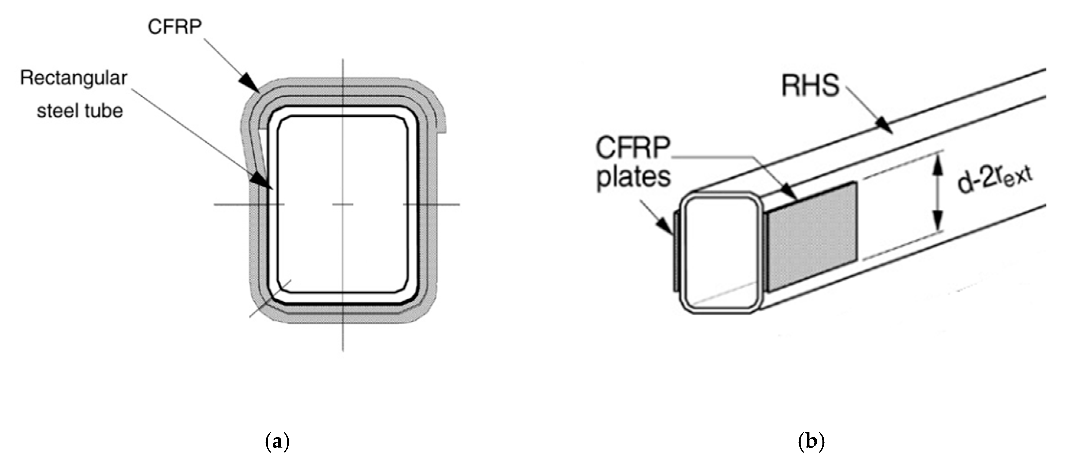
Figure 5 below shows the typical details.
3. Reinforcing connections
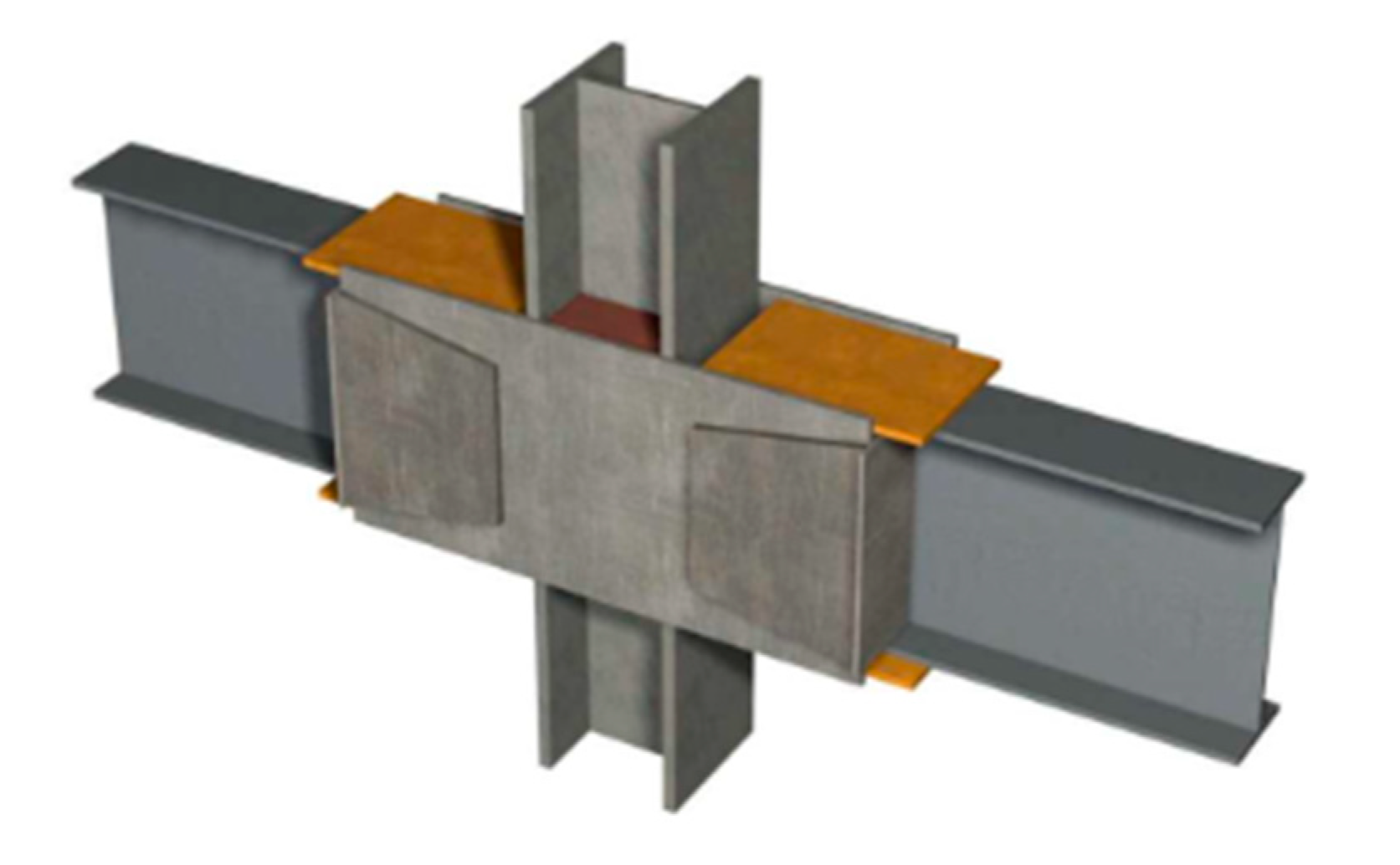
Inadequate steel connections can be strengthened in several ways. These include enhancement of braced connections, adding steel cover and web stiffener plates, conversion of single shear connections to double shear connections through plates and/or angles, addition of welding along the connection perimeter, or thorough cleaning of the existing welds and replacement of bolts with fasteners of high strength. For example, the connection between a column and a beam can be strengthened with the so-called side-plate retrofitting system (
Figure 6), where parallel full-depth side plates are applied to provide the physical separation between the column face (flange) and the edge of the beam to moderate concentration of stress. The parallel full-depth side plates achieve their role by acting as discrete continuity elements connecting the column and the beam [
11]. They are, therefore, designed with suitable strength and stiffness to enhance the transmission of significant plastic behavior to the beam from the connection system. Strengthening of connections must consider maintenance issues as the greenhouse environment is aggressive.
4. Increasing the stiffness of the structure
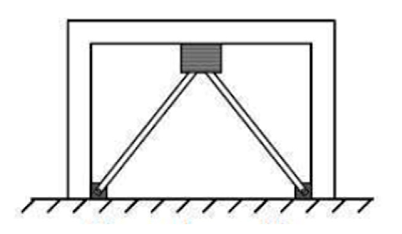
A typical problem of the greenhouse structures is the excessive displacements due to the fact that the structure is made of small cross-sections with small stiffness. The most common methods used to increase the structure stiffness include adding diagonal braces, converting gravity frames to moment-resisting frames, and/or increasing bending and axial stiffness of the columns.
The most efficient and popular strengthening method is the use of braces (
Figure 7). This can be attributed to the fact that braces do not require other complex strengthening methods and they provide the capacity needed; they represent a good implementation, as they have a lower overall cost and are easily applied.
5. Case Studies—Assessment and Strengthening of Two Greenhouses
Two greenhouse structures, a vaulted and a Venlo-type, presented in studies “Analysis of the collapse of a greenhouse with vaulted roof” [
14] and “Additional design requirements of steel commercial greenhouses in high seismic hazard EU countries” [
15], respectively, were used in this study.
The vaulted greenhouse is located in Greece. A section of the greenhouse collapsed during a day with moderate wind and heavy snowfall. The greenhouse failed due to the combined effect of snow and wind at levels above the design of the greenhouse, coupled with the elimination of several internal structural columns. The Venlo-type greenhouse is a commercial product made in The Netherlands designed according to Eurocodes with the local parameters of The Netherlands for wind and snow.
In this study, the structural adequacy of these two structures was assessed under specific parameters of wind and snow according to Eurocodes. As the information for both greenhouses came from the literature, the soil conditions were not known. The soil conditions are related to the support conditions of the columns, given that the foundation of the greenhouse columns is usually made by isolated spread footings. For this reason, fixed supports were used for the steel columns. This is a non-conservative approximation as the fixed conditions are favorable for the steel structure in terms of internal forces (M, V, N) and displacements.
5.1. Structural System of Vaulted Greenhouse
The greenhouse covers an area of approximately 7500 m
2, while the plan measures 76 m × 96 m. The steel profiles are galvanized and are of grade S275 in accordance with EN1993-1-1 [
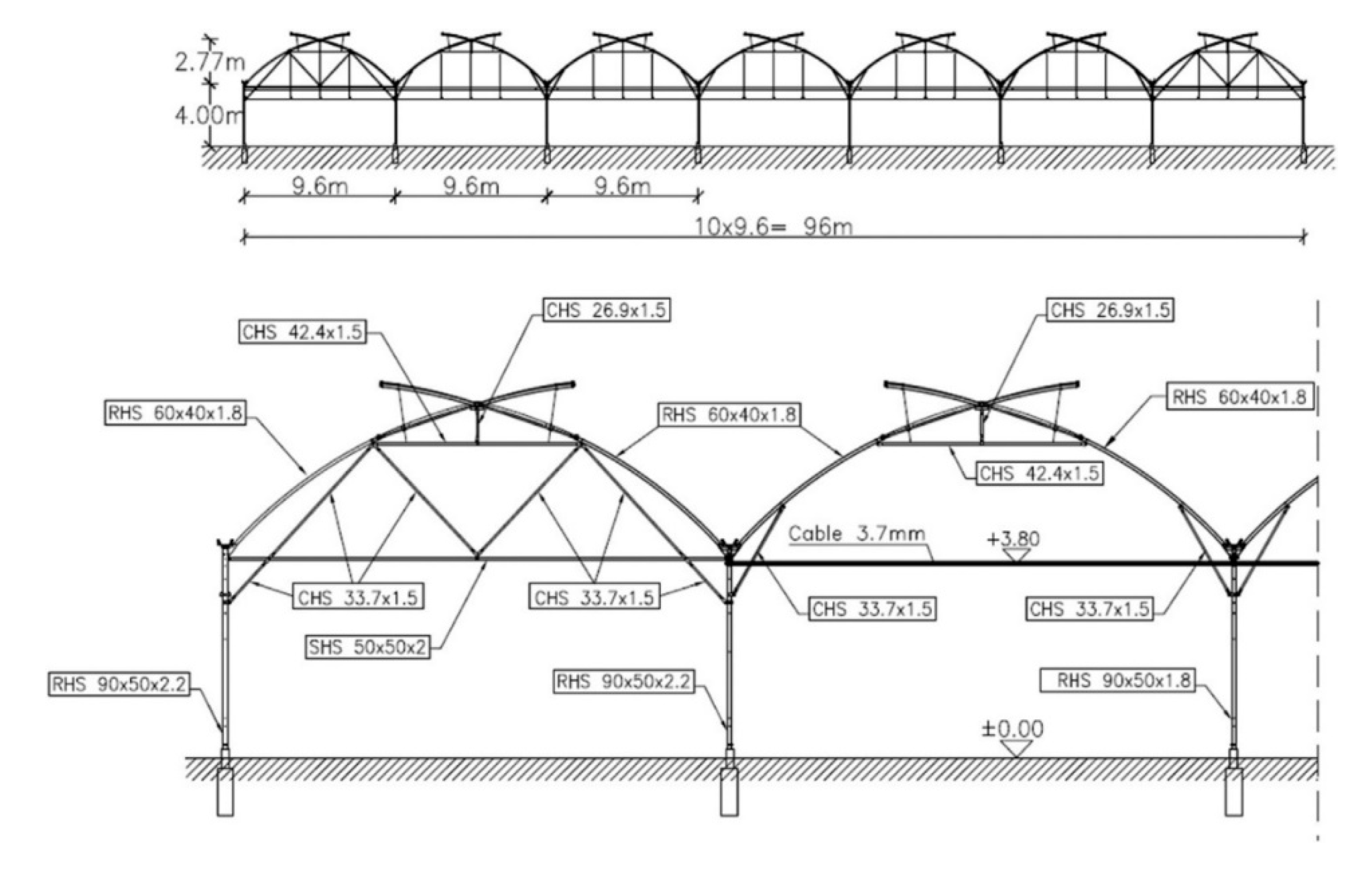
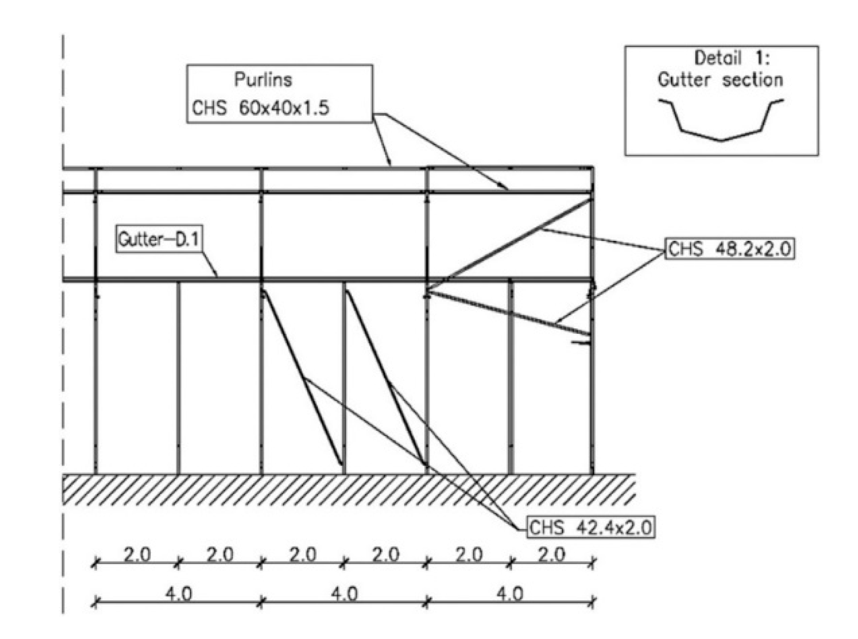
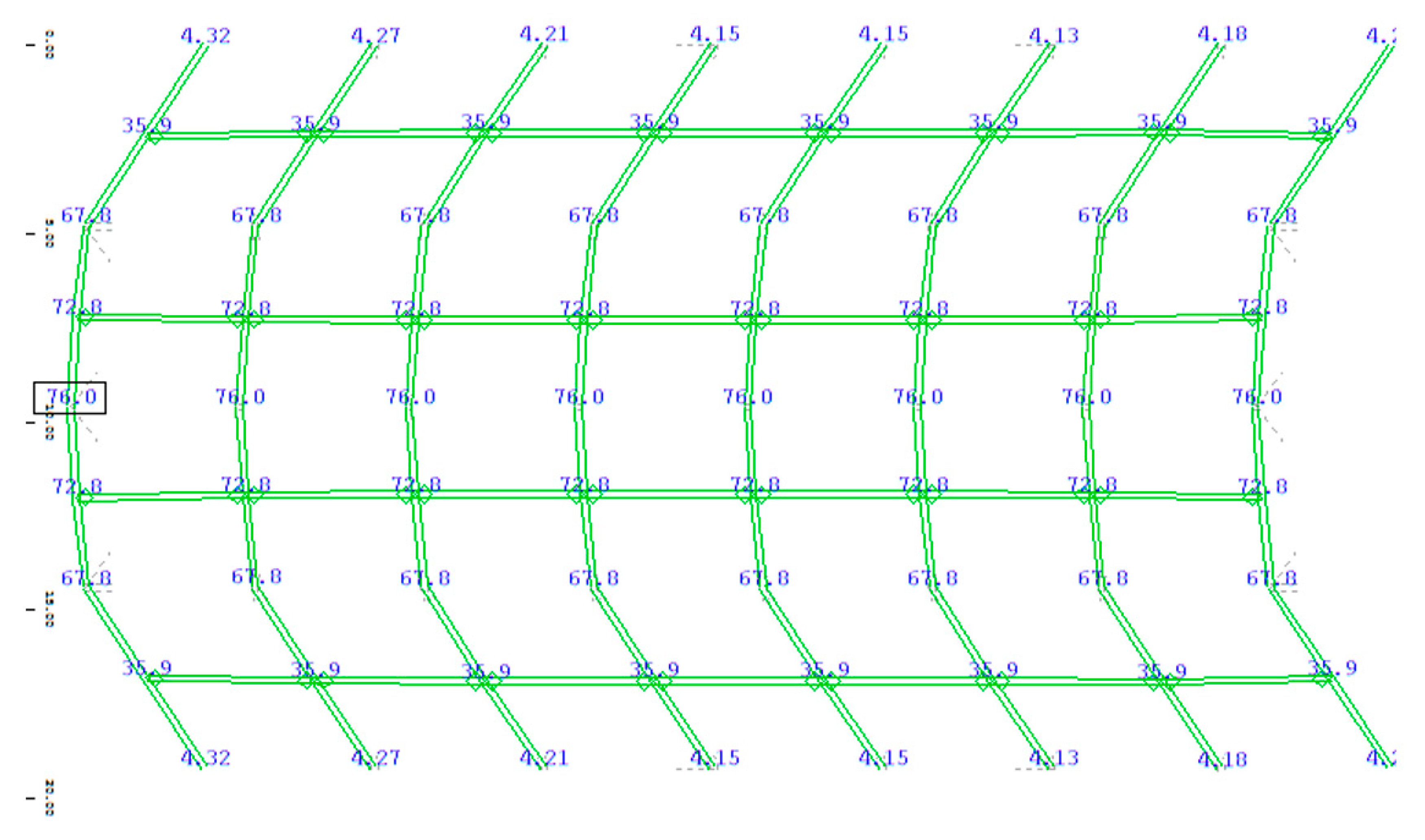
5]. The typical layout of the greenhouse is as shown in
Figure 8 and
Figure 9. Transversely, the structure consists of 10 bays with a span of 9.6 m. The height of the vaulted roof at the location of the gutter is 4 m while it is 6.77 m at the ridge. The steel profiles at the vaults are RHS 60 × 40 × 1.8. Columns of RHS 90 × 50 mm profile support the arches. The thickness of the columns is 2.2 mm for the rows on the outer side, while the thickness of the intermediate rows is 1.8 mm. Ties are used to connect the columns at the top. The ties have a diameter of 3.7 mm. The outer columns are connected using SHS 50 × 50 × 2 mm steel profiles with the ability to transmit compression and tension. Compression renders the ties ineffective and, hence, their contribution to load transfer is limited. Pre-tensioning of the cables is frequently done to ensure that the resulting force is always tension and they remain useful in load transfer. Internal ties are anchored by the triangulated trusses present on the external bays of the vaults. CHS 33.7 × 1.5 profiles provide the diagonal trusses, while CHS 42.4 × 1.5 profiles make up the horizontal beam. Inclined braces provide the internal vaults near the ends using CHS 33.7 × 1.5 profiles supporting the columns. Additional front columns are present at the back and front facades where two columns are added at each vault giving the cladding the required lateral support. Longitudinally, the distance between the vaults is 4 m. The distance between the columns in the vaults is 2 m since there is one intermediate column between the vaults. CHS 42.4 × 2 profiles located longitudinally act as the wind braces. Additional braces are present with a cross-section of CHS 48.2 × 2 between the first inner frames and external frames. There is the provision of three purlins for each vault whose profile is RHS 60 × 40 × 1.5. Two purlins are located between the gutter and the ridge, while one purlin is at the ridge. Hat section beams are used in column connections which also act as gutters. The purlins have a span of 4 m, which is similar to the distance between columns, while the span of the gutters is 2 m and is equal to the separation between the columns. However, this was not the case for frames with missing columns (removed or not installed at all), that is, the span was 4 m. Plastic film was used as the greenhouse cladding [
14]. The type of greenhouse is B15 according to EN 13031 [
1].
5.2. Structural System of Venlo-Type Greenhouse
The area covered by the greenhouse is approximately 604.8 m
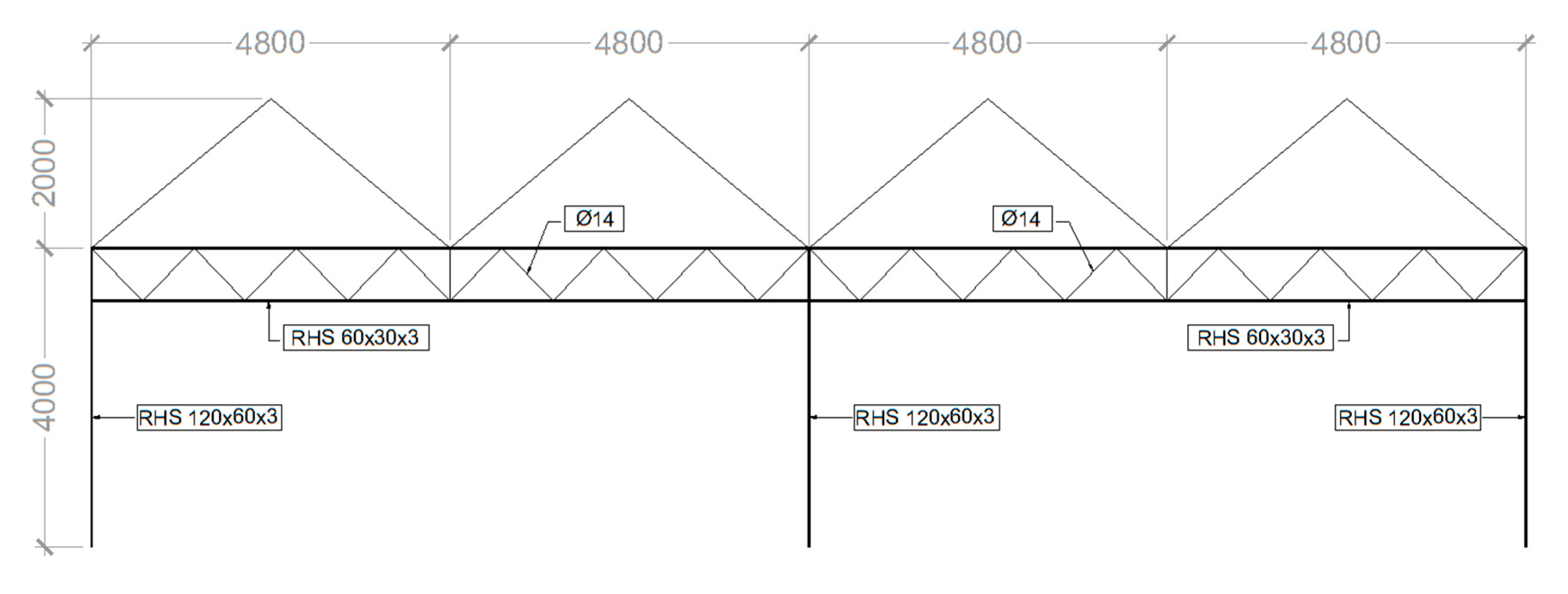
2. The plan measures 19.2 × 31.5. The steel profiles are galvanized and are of grade S235 in accordance with EN1993-1. Transversely, two bays with a span of 9.6 m make the structure with Gabic even roofs which measure 4.8 m at the gutter and 6 m at the ridge. The span between typical frames is 4.5 m. Its typical layout is indicated in
Figure 10.
The main truss beam consists of RHS 60.030.0 × 3.0 and Ø14 diagonals. The trusses are supported by columns of profile RHS 120.0 × 60.0 × 3.0. Vertical bracings are Ø12. Longitudinal beams are SHS 140.0 × 3.0. The greenhouse cladding is made of glass, and the type of greenhouse is A15 [
15].
5.3. Characteristic Values of Actions
The structural adequacy of the two aforementioned structures was assessed for the actions described below according to EN 13031 [
1] and Eurocodes [
2,
3,
4,
5].
The self-weight of the cladding of the vaulted and Venlo-type is 0.13 kN/m
2 and 0.50 kN/m
2, respectively. The minimum allowable permanent installations actions are 70 Pa according to EN13031 [
1]. According to Eurocode 1-1-4 [
4], the ultimate value of the basic wind velocity is v
b,0 = 27 m/s. EN 1991-1-4 [
4] was used to determine the probabilistic factor for the minimum reference of 15 years as c
prob = 0.93. The basic wind velocity was taken as vb
15 = 25.1 m/s. According to Eurocode 1-1-3 [
3] for Zone 1 of snow and adjustment of the ground, snow load according to the design return period of 15 years is s
k = 0.30 kN/m
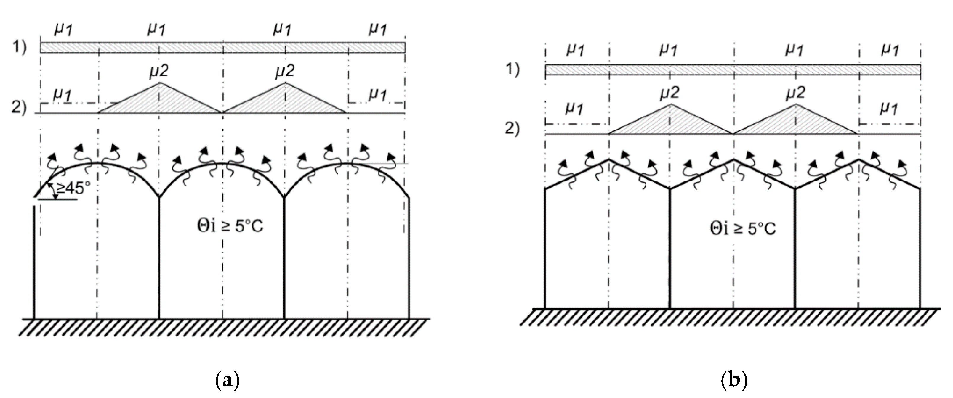
2. The snow load shape coefficients are μ
1 = 0.80 and μ
2 = 2.0. Crop loads are not considered as they are usually minor, and there was no information in the literature. Summary of the used actions is presented in
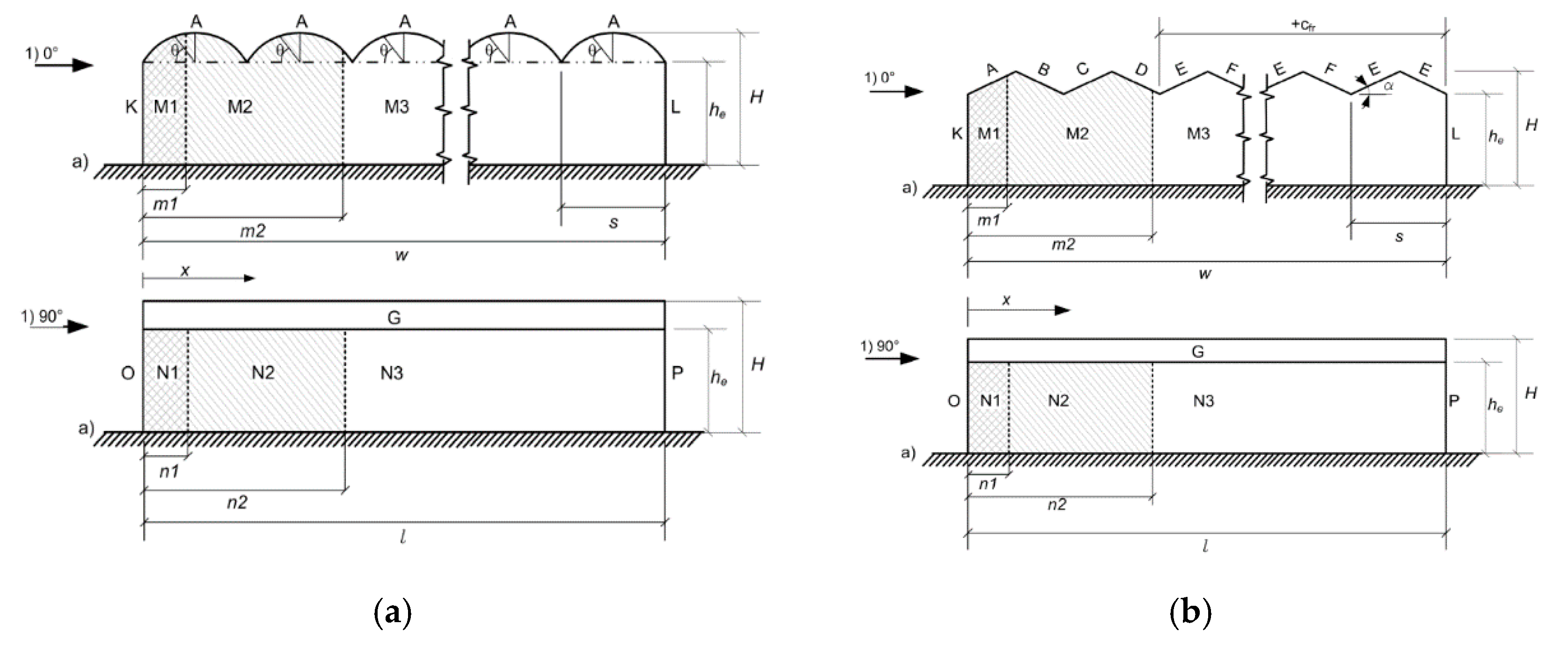
Table 3. The used wind and snow models are presented in
Figure 11 and
Figure 12 and the external pressure coefficients are presented in
Table 4.
5.4. Combination of Actions
The actions of interest combined according to EN 13031 were as follows:
For the case study, the partial factors are specified in sets; for actions which are permanent, γG,j = 1.20/1.00, while, for varying actions, γQ,j = 1.2(0.0 when favorable). The combination coefficient for the wind or snow actions is ψQ = 0.60.
5.5. Structural Analysis
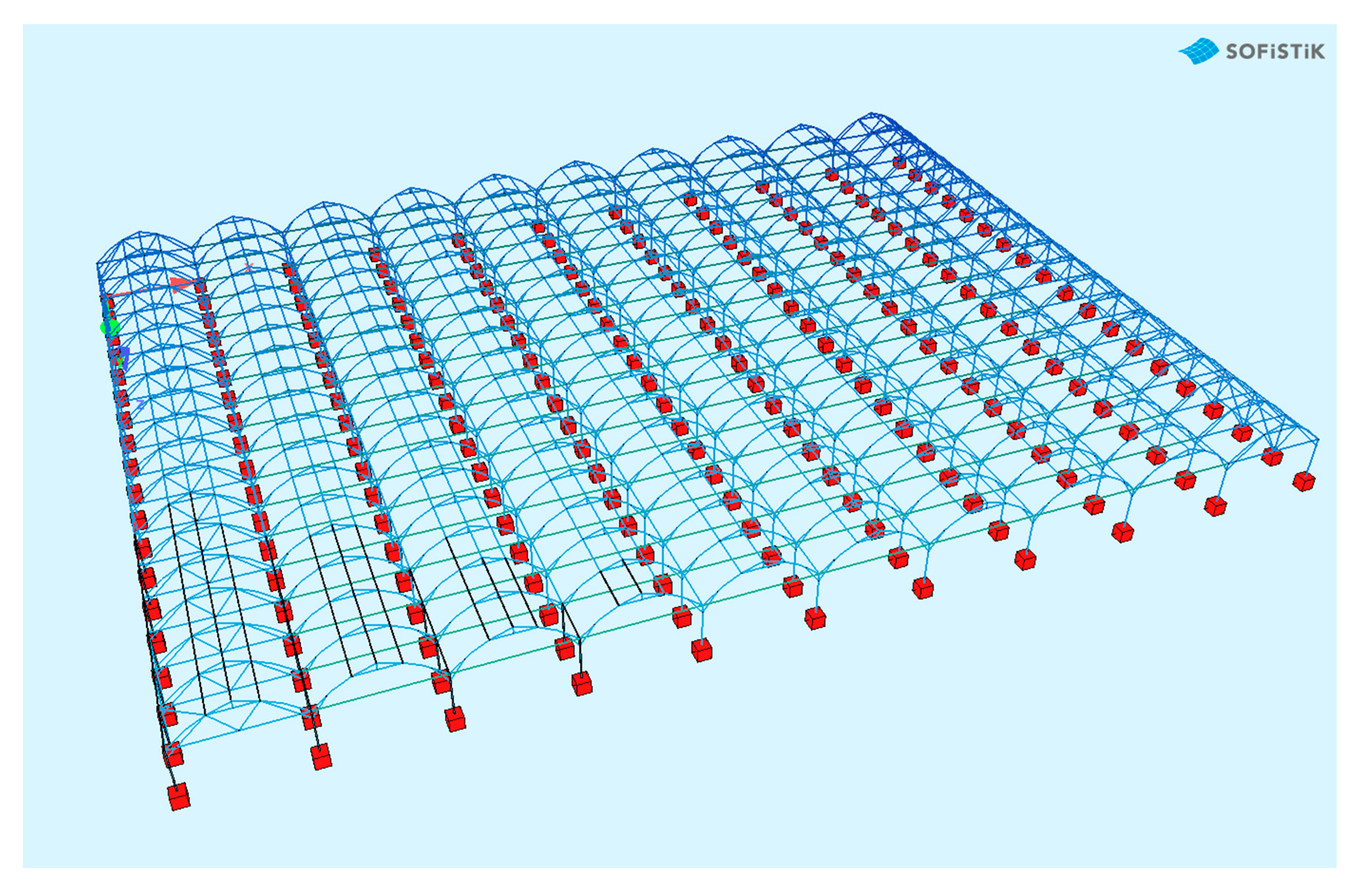
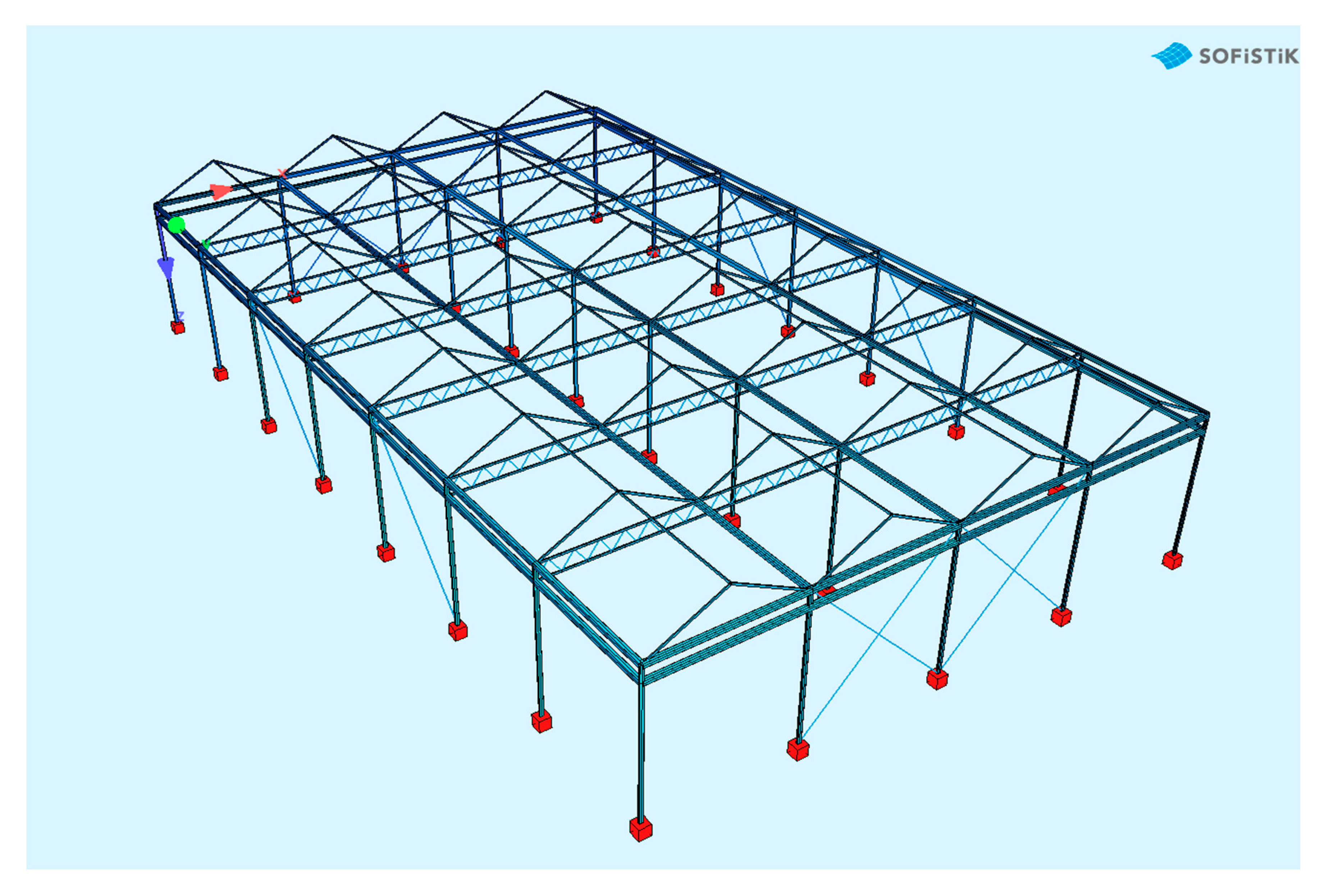
SOFiSTiK [
16] software was employed to generate the three-dimensional (3D) model of the entire structure of the greenhouse. Beam elements were used to represent the bracing, purlins, truss bars, arches, and columns, while cable elements were used to represent the tension ties. The cross-sectional properties and the material used for the steel represented the real structure. All main members were considered monolithically connected. To improve the accuracy of the generated model, boundary conditions at the structural member ends such as braces and diagonals were taken as hinged elements. Glass panels in Type A greenhouses should be considered as structural elements placed in the greenhouse structure to close the building, and they do not contribute to the stability of the main structure [
1]. Typical models are shown in
Figure 13 and
Figure 14.
5.6. Assessment of the Structural Capacity of Each Greenhouse
For both the vaulted and the Venlo-type greenhouses, all the required ultimate limit state (ULS) checks were performed. More specifically, the bending and the cross-sectional, instability resistance of the members (due to buckling), and the cross-sectional resistance to fracture under tension [
5] were assessed by member checks.
Axial, compression bending and the shear resistance of each cross-section were calculated as shown in
Table 5.
Buckling resistance of each cross-section was calculated as shown in
Table 6.
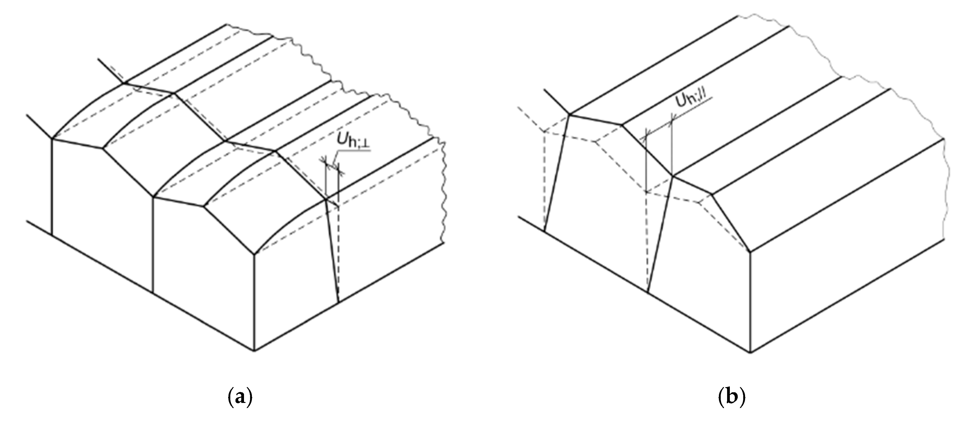
Serviceability limit state (SLS) checks were also performed for the Venlo-type greenhouse where frame displacement limits the cladding system. The horizontal displacements of the greenhouse at the gutter level, as well as perpendicular to the gutter, were checked. The limit values depend on the U
h;gw/swlim, U
h;rlim, which are the limiting values of the displacement in the horizontal direction of the gable wall at the gutter level perpendicular or parallel to the gutter, as a result of the cladding panel clearance in the gable wall and displacement of the roof in the horizontal direction parallel or perpendicular to the gutter, respectively, due to cladding panel clearances on the roof (
Figure 15 and
Table 7).
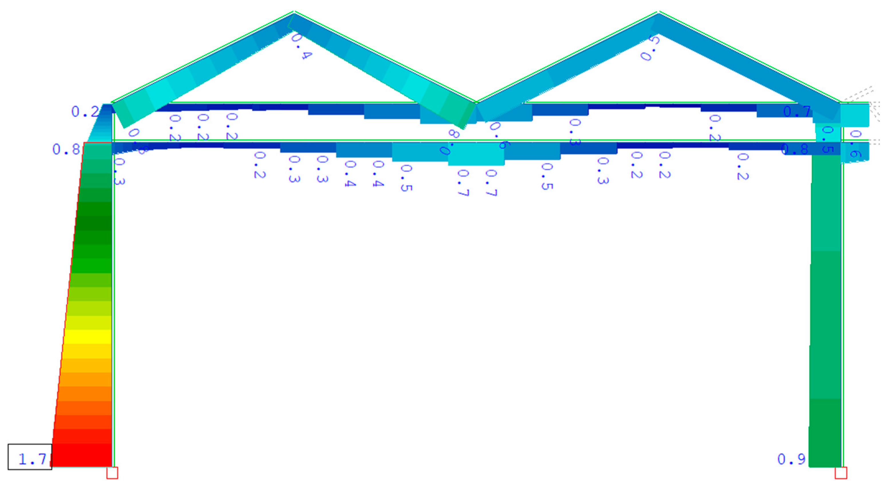
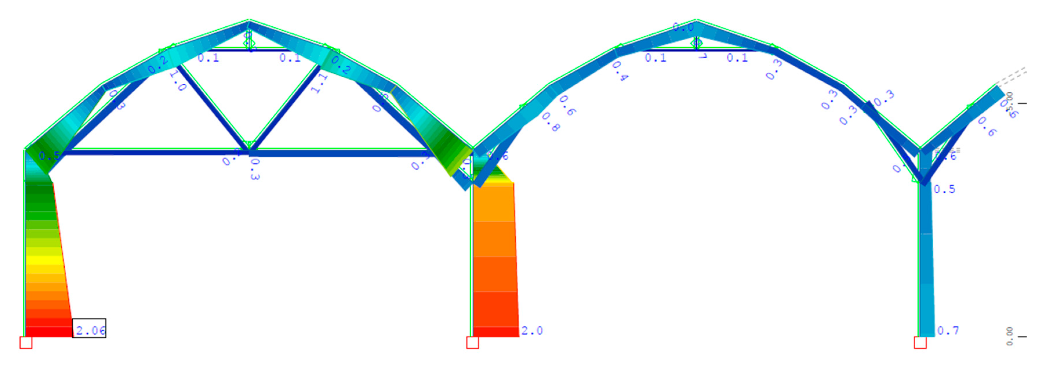
More specifically, according to the structural calculations, the capacity of the bending moment at the cross-section of the main columns on the perimeter of both the vaulted and Venlo-type greenhouses was exceeded (
Figure 16 and
Figure 17). The ULS is the critical combination with the wind as a leading variable action. In the Venlo-type greenhouse, the horizontal displacement parallel to the gutter due to wind actions was greater than the limit of 60 mm (
Figure 18 and
Table 8).
These types of inadequacies are common in such structures as they are usually designed to allow for the highest possible transmittance of light. This leads to the design of lightweight structural frames susceptible to large horizontal displacements. Furthermore, to allow for services (installation, crop, etc.), the placement of vertical bracings in the frames is eliminated and the frames resist horizontal loads via their bending resistance.
5.7. Strengthening of the Greenhouses
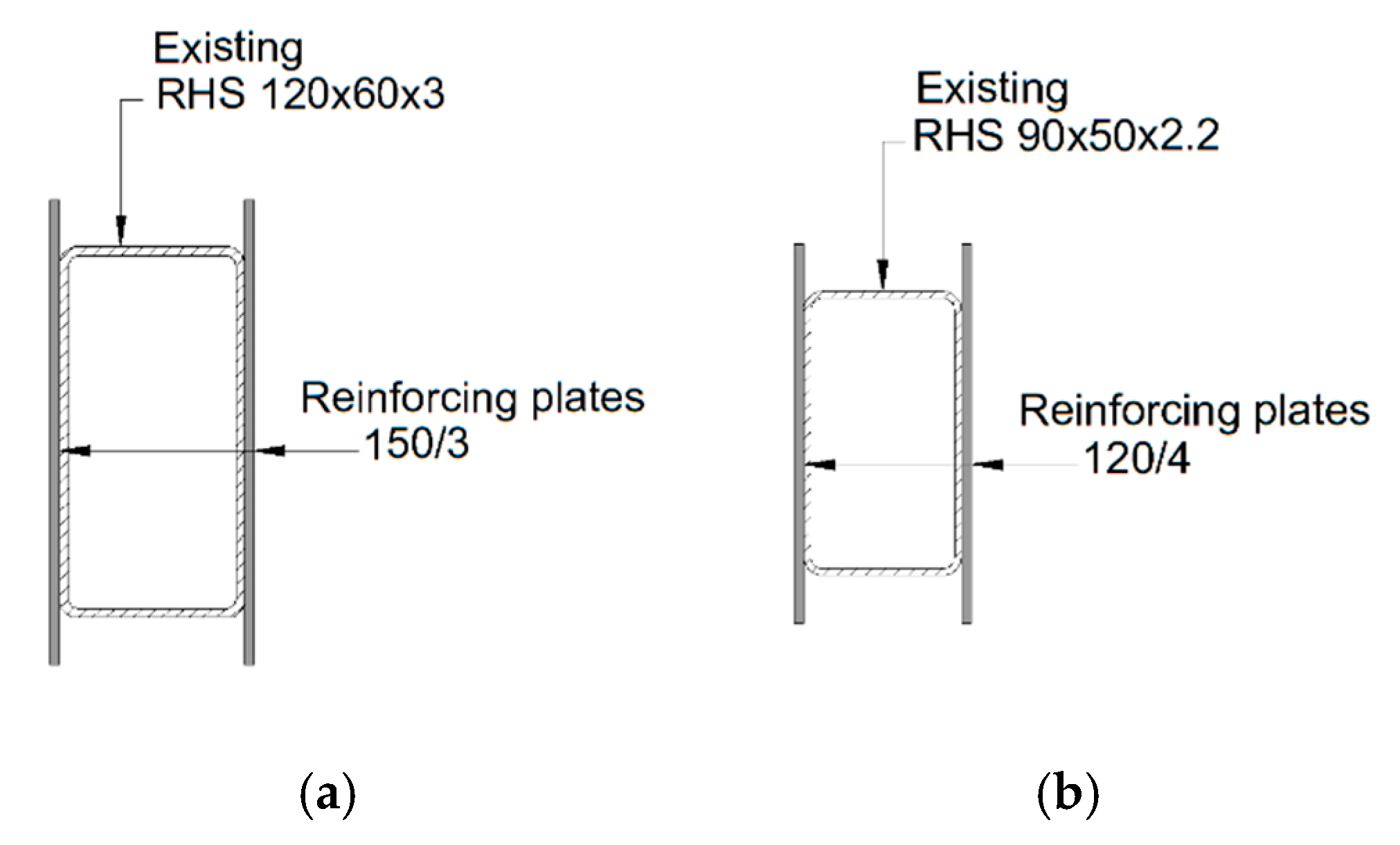
The columns of both greenhouses have insufficient design resistances due to combined compression and bending. Strengthening the columns by welding steel plates to increase their capacity was selected as the strengthening technique because it is a safer and simple way to strengthen a cross-section compared to FRPs as already mentioned before. The final proposed cross-sections are indicated in
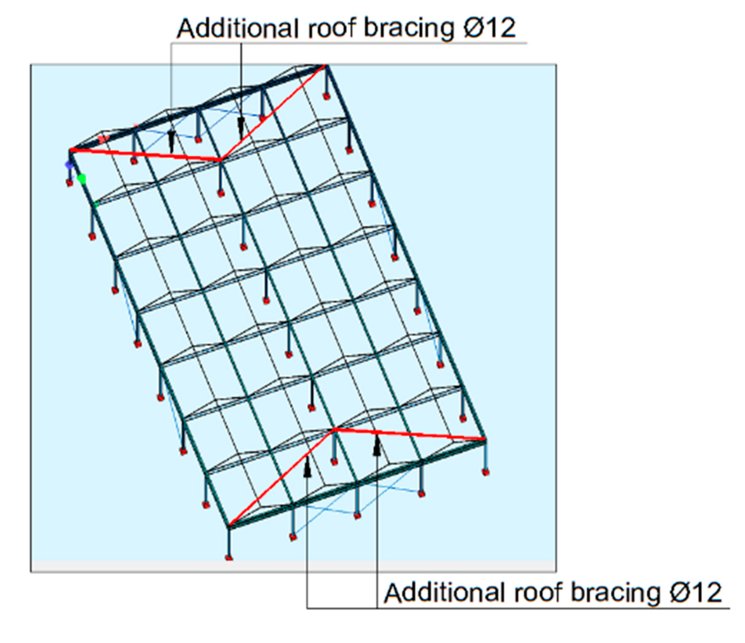
Figure 19 for each structure. To decrease the design displacements on the Venlo-type greenhouse roof, bracing Ø12 was added in the structure as indicated in
Figure 20. The strengthened structures were re-analyzed and re-checked following the assessment procedure presented in
Section 3.4, and their adequacy was confirmed for both ULS checks (
Table 9) and SLS checks (
Table 10).
5.8. Cost Estimation
An accurate cost analysis, between (a) the demolition and reconstruction, and (b) the strengthening, should include the long-term loss of crop production, the demolition cost, and the cost of reconstruction. As this information is not generally available, the cost estimation of the strengthening of both greenhouses was determined as the ratio of strengthening versus the initial construction cost of the steel structure and, for simplicity, the ratio of the steel weight needed for strengthening vs. steel weight of the initial steel structure, e.g., the increase in steel structure weight after the strengthening. The cost per kg of steel used for strengthening is higher than the cost per kg for the initial steel structures, as it requires increased workmanship per kg; generally, it can be considered as a retrofit cost of 1.5 €/kg, but this depends on many parameters. On the other hand, several other costs (transportation, foundation, excavations, etc.) are ignored for the initial steel structure. The weight comparison is presented in
Table 11, which shows that the strengthening weight ratio to the initial steel structure weight was only 36.57% for the vaulted and 13.6% for the Venlo-type structure. These ratios demonstrate that strengthening is an advantageous solution for the capacity upgrade of existing greenhouses.
6. Conclusions
For a well-designed greenhouse structure, it must satisfy some key objectives such as low construction and operation cost, efficient mechanical properties, efficient ventilation systems, low heat consumption, and allowance of high light transmittance. These objectives lead to the design of structures with a small cross-section and elimination of bracings. Also, steel greenhouse structures are generally constructed by sole contractors who use quick and empirical structural calculations or pre-engineered solutions, and it is also common to import standard greenhouses from abroad, mainly from The Netherlands, Italy, and France, and less commonly from Great Britain and Israel. Evidently, these objectives lead to code-deficient existing structures, and there is often a need for structural interventions. The major structural types of greenhouses are described in this paper, and their structural methodology assessment according to EN13031 and Eurocodes is analyzed. The most common types of strengthening techniques that may be applied to greenhouse structures are outlined. Case studies of assessment and strengthening of vaulted and Gabic (Venlo-type) greenhouses are presented. Both types were found to have inadequate bending moment capacity combined with compression of columns due to horizontal loads such as wind with combined snow, while the Venlo-type greenhouse also experienced excessive horizontal displacements. In both structures, reinforcing steel plates are commonly welded to the columns to increase their bending capacity and stiffness. In the Venlo-type roof, bracings are commonly added to decrease the excessive horizontal displacements.
The main conclusion of this study is that existing greenhouse structures that are commercially imported from other countries or those designed based on empirical structural calculations often require structural upgrades to resist design forces according to Eurocodes. A methodology of assessment and some strengthening techniques are presented herein. Moreover, the cost analysis demonstrated that the strengthening of a greenhouse structure is a very advantageous solution, as the construction cost is low, and it does not interrupt crop production. Another approach could be the evaluation of wind loads with advanced wind models [
17] or Computational Fluid Dynamics (CFD) models [
18,
19,
20,
21] which may lead to less conservative wind pressures than the requirements of EN13031-1 [
1] and, thus, more meticulous design and retrofitting methods.
