1. Introduction
The rapid advancements of the third industrial revolution and computer technology have ushered in a new era of “smart life”, where integration with smart devices, cities, airports, and more is becoming a reality. In this context, many urban designers and planners did not anticipate the pace of technological progress and its continued development. However, the city of Macao is actively promoting education, training, and awareness related to smart city development, intending to significantly enhance the overall quality of life.
One area where smart technology can have a significant impact is the airport, which is a crucial infrastructure that can benefit from innovations such as smart parking and automated baggage handling.
While there have been successful implementations of smart technology in airports around the world, such as London Heathrow [
1,
2] and Singapore Changi Airport [
3], most research studies focus on improving the “in-system” experience, with less attention being paid to the “out-system”, such as the parking lot. This is where our contribution comes in.
In this paper, we propose an innovative, economical, and plug-and-play smart parking system for Macao International Airport that integrates various methods such as IPM (inverse perspective mapping), object detection with deep learning, and a guidance system with a rig of multiple cameras. Our system is easy to install, making it an attractive solution for other airports looking to adopt smart parking technology. The possibilities of smart technology are endless, and our contribution is just the beginning of what can be achieved with the integration of smart technology in airport management.
We use a 3D scene to simulate our system and its functions. To evaluate the accuracy of our proposed method, we conducted an experiment where 977 vehicles were placed in 100 randomly generated scenes, and the images of the six cameras and the coordinates of the placed vehicles were collected. Our proposed method successfully located 948 vehicles with an accuracy of 97.03% and a mean distance error of 8.59 pixels, which is acceptable given the average size of the vehicles. These results demonstrate the effectiveness of our proposed method in accurately detecting and locating vehicles in parking lots.
Overall, our proposed smart parking system can greatly benefit airport management by improving efficiency and reducing costs. Our contributions can be summarized as follows:
We proposed a simple yet effective smart parking system based on cameras that enhances the parking experience for users.
We designed basic functions for this system, including parking lot modeling, vehicle detection, parking space management, and guidance.
We adopted many mature algorithms used in the corresponding field, which provide many solutions to troubleshooting maintenance problems.
This paper is organized as follows. The related works are reviewed in
Section 2. Our system architecture and its components are presented in
Section 3, while simulation results using a simulated 3D scene of Macao International Airport are discussed in
Section 4. We discuss our system and its limitations in
Section 5. Finally, we conclude our work and its limitations in
Section 6.
2. Related Works
Smart parking systems have become increasingly popular as they help solve the problem of parking in urban cities, improve parking efficiency, and create smart cities. Smart parking is an important component of the larger trend toward digital technologies in all areas of customer service, and its implementation has been studied in various contexts. The benefits of smart parking include streamlining parking systems, reducing congestion, and improving the overall user experience.
In [
4], the authors analyze the implementation of smart parking as a part of the smart airport concept. The authors argue that airports are increasingly interested in improving customer services, and parking is an important area of customer service that airports provide to their customers. Smart parking can help airports streamline their parking systems, reduce congestion, and improve the overall passenger experience. Similarly, in [
5], the authors discuss the high acquisition costs associated with constructing a smart parking lot.
Most research studies on smart parking aim to either upgrade existing parking systems or implement new ones, and there are two trends in terms of smart parking designs: IoT-based and visual-algorithm-based methods.
IoT-based methods: ESDTW [
6] is an underground parking navigation system that estimates vehicle position using LTE signal strength and smartphone sensors. However, it has limitations in terms of its signal availability and performance in weak or noisy areas and may not be compatible with other wireless technologies. An IoT-based smart parking management system [
7] uses Arduino components, Android apps, and infrared sensors to detect and reserve parking spaces, but requires many sensors and controllers for installation and maintenance. The Edge AI Parking Surveillance System [
8] detects parking occupancy in real time using AI algorithms and edge computing, with excellent performance demonstrated in a real parking lot for three months. However, these approaches may all face security challenges such as data leakage, unauthorized access, and malicious attacks on IoT devices.
Visual-algorithm-based methods: The smart parking system in [
9] uses image processing and AI to assign parking spaces and provide parking information and user recommendations. However, the paper lacks experimental results, comparative analysis, risk assessment, and ethical considerations. Aerial Image Parking Lot Analysis [
10] uses elevation information to analyze and visualize parking lots from aerial images, including vehicle detection and simulation. However, it cannot be applied to smart parking in airports because it is limited to aerial images of airports. Image Processing Parking Space Detection [
11] uses cameras and image processing to detect vacant parking spaces and display real-time data, but lacks analysis and comparison with other systems.
Overall, IoT-based methods are reliable but may require many sensors and devices, leading to high acquisition and maintenance costs. Visual-algorithm-based methods, on the other hand, offer good performance in their respective scenarios, but may not be easily applicable to other types of smart parking systems, making their methods less persuasive.
3. System Architecture
In this section, we will describe the architecture of our proposed smart parking system based on surveillance videos.
Figure 1 illustrates the various major components of the system. The operations in the preparation stage are only required to be performed once before the system starts running. During preparation, the system takes images from its cameras to generate coordinate relations and extract parking spaces. When the system is running, it uses images from its cameras to detect vehicles and guide users.
3.1. Parking Lot Coordinates Mapping
Perspective transformation is widely used in image restoration, which is the projection of an image onto a new view plane. For example, when two cameras take pictures of a plane at different angles, the coordinates of the same point in the plane are different in the two pictures. Perspective transformation achieves the function of mapping the same point in the two pictures. By the same token, when multiple cameras are taking pictures of a parking lot, the picture of each camera contains information about a part of the parking lot. Using this series of transformations can make it possible to obtain aerial view images without the need for special equipment, such as a UAV.
Many methods can achieve coordinate mapping, such as stereo-based [
12], adaptive-based [
13], and 4-point-based [
14] methods. The 4-point-based method is recommended as the preferred option in our system among these methods because it has fewer factors (parameters of algorithms, position or pose of cameras changed by installation mistakes, or extreme weather) involved. In addition, the 4-point-based method completely satisfies the requirements of this system with regard to robustness; therefore, we apply this method to our system.
There are two steps to achieve parking lot coordinate mapping using a 4-point-based method:
Obtain the perspective transformation matrix and calculate the perspective transformation from the four pairs of corresponding points;
Apply a perspective transformation to images via the perspective matrix.
The first step can be modeled by Equation (
1):
is the source matrix, which is a matrix of coordinates of four points on the source image, requiring any three of the points to not be co-linear. Similarly,
is the target matrix, which is a matrix consisting of the coordinates of four points on the target plane, requiring any three of the points to not be co-linear and for each point to correspond to
.
X represents the perspective transformation matrix,
x and
are the coordinates of the four points in the source image and target plane, respectively, and these points satisfy the constraint of no co-linearity in geometry.
Next, we expand Equation (
1) as follows:
from which
defines transformations such as rotation, scaling, etc.;
is the translation vector; and
is the projection vector. LU decomposition can be used to solve this, and then we can obtain the perspective transformation matrix
X.
Then, we can apply this matrix to an image to obtain any transformed point in the target plane. This process could be formulated by the following equation:
After solving
X in Equation (
1) and applying that value of
X to Equation (
3), we can obtain the coordinate mapping between one camera and the aerial view using 4-point-based IPM.
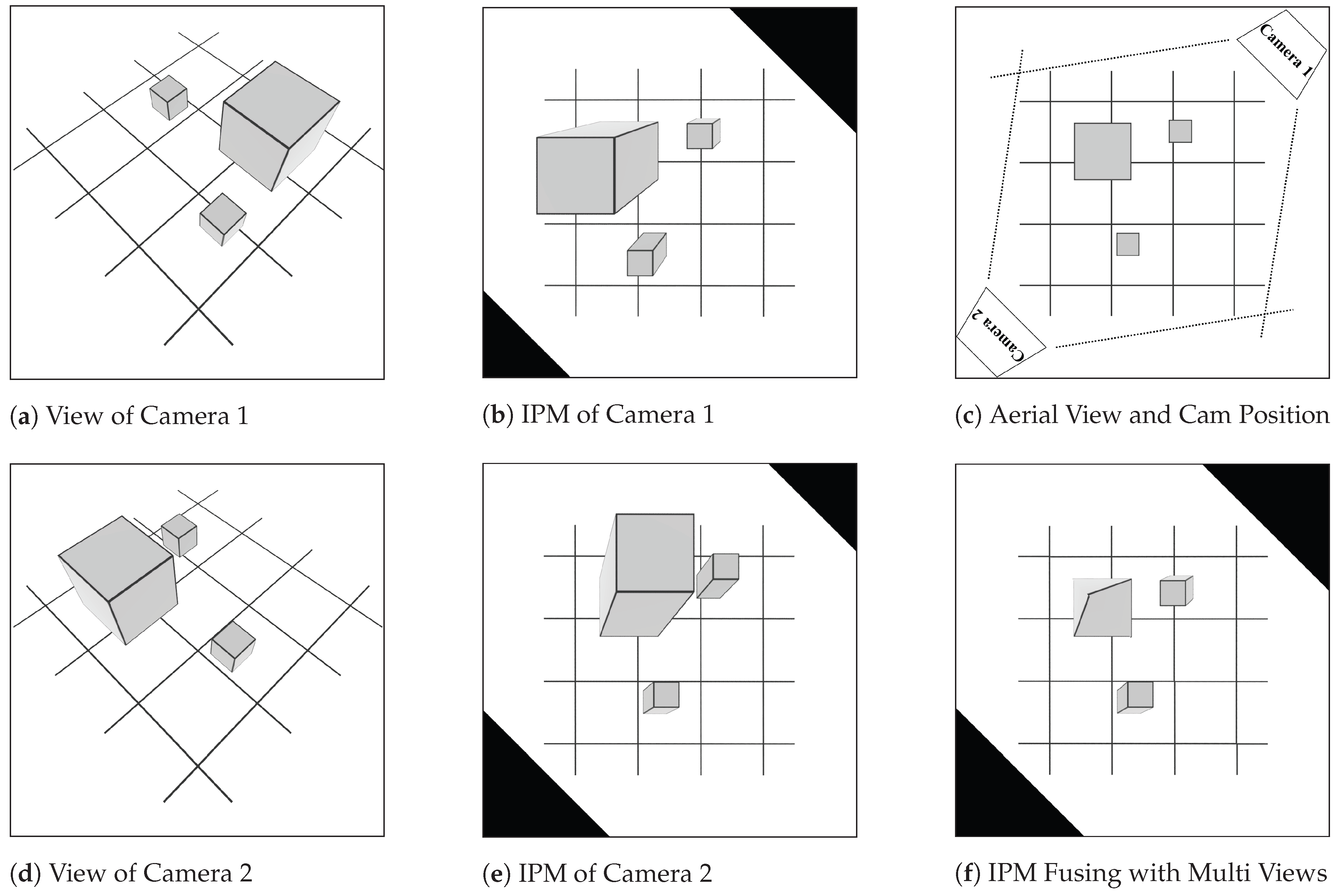
Figure 2 introduces the workflow of 4-point-based IPM. For simplicity, these intersecting lines in
Figure 2a,d are used as an abstraction of the parking lot. At first, when obtaining the camera frame and the initialization of the system, it is necessary to know the pixel coordinates of at least four marks. The marks are usually small and clear, such as an end of a line or a line–line intersection. Secondly, the coordinates in the real world should be obtained from the aerial view (shown in
Figure 2c); however, it is difficult to obtain the aerial view since the airport is so strict in controlling UAVs. The coordinates of the real world could be obtained by converting them from virtual coordinates (scaled in the computer). In the following works, virtual coordinates are used in representing the position of objects in the parking lot. Furthermore, by measuring the length and width of each parking space and the width of routes in the real world, we can assign a virtual coordinate to corners of parking spaces where mark points are usually selected from. Then, by applying 4-point-based IPM, the projected relationship between virtual coordinates and camera frames can be obtained. Then, as shown in
Figure 2b,e, based on these two sets of virtual coordinates, the computer can calculate the IPM result of the view of the camera. Finally, fusing all of the IPM results can output a fused aerial view image which is extremely similar to the aerial view in terms of the relationship of coordinates (as shown in
Figure 2c,f). In this step, the fused image is generated by calculating the nearest camera for each pixel and then copying its corresponding pixel.
3.2. Parking Lot Modeling
Before the system starts to detect vehicles, a precise model of the parking lot is necessary. This is useful in determining whether a vehicle is located in a parking space or not. Some routes in parking lots are designed to be one-way, which should be followed when guiding vehicles. The model can be labeled manually because this task only needs to be completed once before the system runs. In this paper, we try to propose a more automatic method.
In the model of the parking lot, information on every parking space and route should be provided. In this section, we will introduce how we extract these two types of information. Note that the locations and heights of cameras are manually provided as this information is difficult to analyze from surveillance images.
3.2.1. Parking Space Extraction
The shapes of parking spaces may vary greatly in different parking lots, but basically, all the parking spaces have two straight lines at two sides, which we consider the most useful characteristic in extracting parking spaces. Therefore, to detect these straight lines, surveillance images covering the whole parking lot are required. In addition, the parking lot should be empty, which ensures that no line will be blocked by vehicles.
After mapping surveillance images to a fused aerial view image, the system can use it to extract parking spaces.
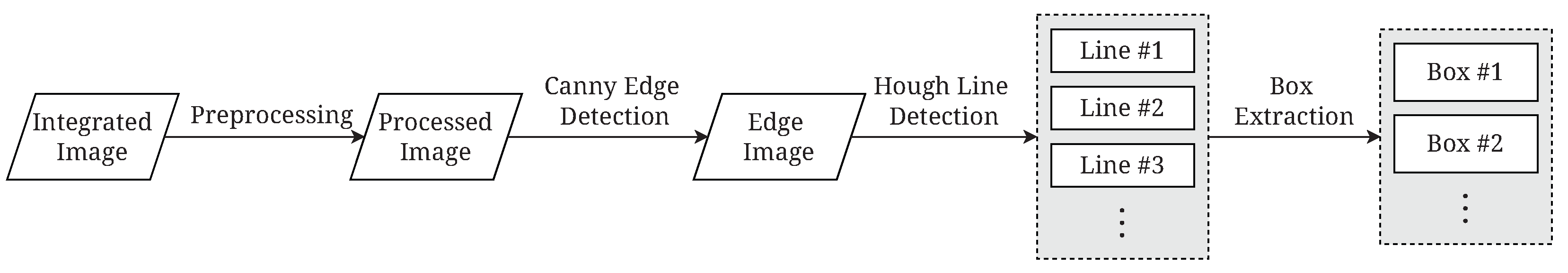
Figure 3 shows the process of parking space extraction using the generated fused aerial view image. The whole process can be divided into two stages: target line extraction and bounding box extraction.
Target Line Extraction: In this stage, the lines of the parking spaces are extracted for constructing bounding boxes. Firstly, the preprocessing stage contains a blur function. When transforming surveillance images to aerial view images, the pixels are mapped onto the fused image. The pixels far from the camera are expanded and distorted. As a result, the edges of transformed lines may be jagged, which affects the performance of the following steps. The blur function can alleviate this situation. Secondly, we use the Canny edge detector [
15] to detect the edges in the fused image. The result of the edge detector is an image containing edges, where the image has the same size as the fused image. To further ensure the edges of the parking space can be extracted as lines, we perform a dilation operation on the edge image in case the edges are shattered. The third step is to extract lines from the edges. A line detection method based on Hough Transformation is provided in [
16]. We use this method to extract lines. The majority of the extracted lines are not from the edges of parking spaces; therefore, we need to filter the lines. Since the fused aerial view image is generated with respect to the real coordinates, the length of parking spaces in pixels can be calculated. Extracted lines with large length differences from the actual length are filtered. In addition, the direction of parking spaces can also be used to filter the lines. For example, if the parking spaces are perpendicular to the edge of the parking lot, the lines that are not perpendicular to the edge of the parking lot are filtered. If there are multiple alignment directions of parking spaces, the lines perpendicular to each direction can be reserved. After this step, the lines reserved should be those extracted from the edges of parking spaces and the length should be similar to the edges.
Bounding Box Extraction: To extract the boxes of parking spaces, we consider repeated boxes with the same size as the characteristic. Similar to filtering lines, the distance of lines, i.e., the width of the parking space, can be calculated.
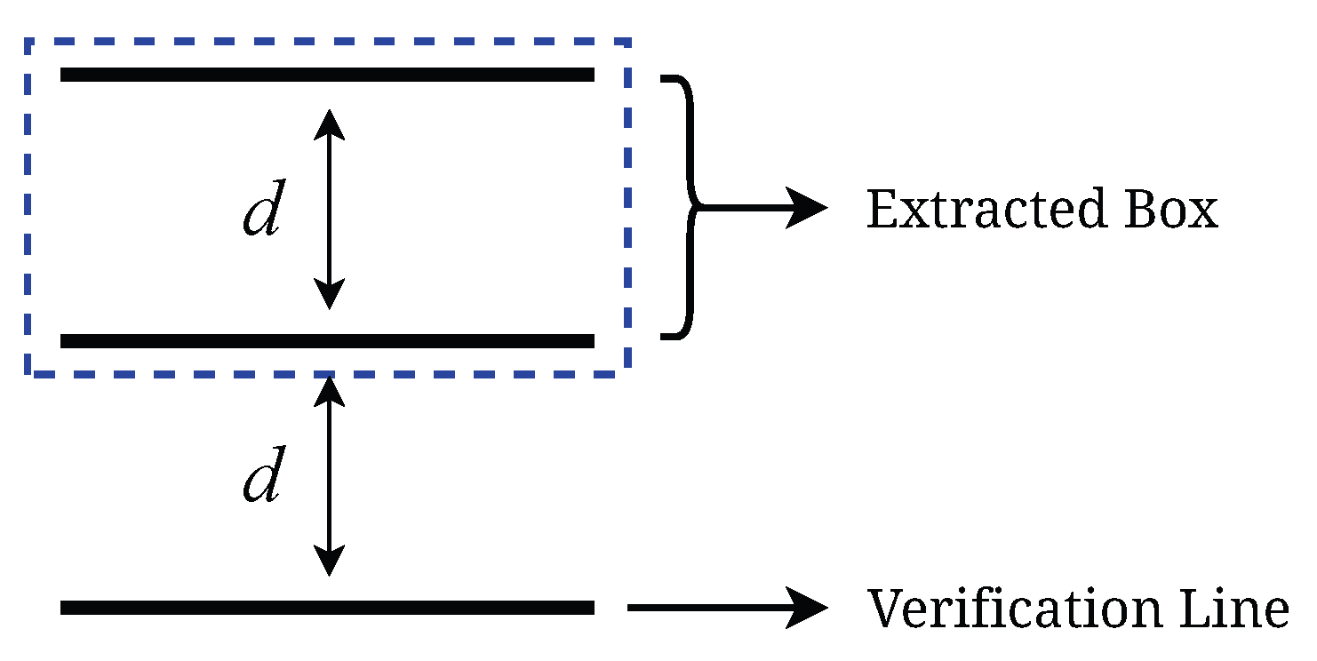
Figure 4 illustrates extracting the bounding box with a verification line. Firstly, when there are two lines with centers in one of the alignment directions and their distances meet the expected length, the box they form is considered as a candidate bounding box. Then, we follow the alignment direction and the opposing direction to check if there exists a verification line. The verification line should have the same direction and its distance to the candidate bounding box should meet the expected distance. If a verification line is found, we consider the candidate bounding box to be a box of a parking space and store it for the next step. If the parking spaces have multiple alignment directions, the lines can be divided into groups depending on their direction, and then we perform the extraction. Finally, sometimes more than one line is extracted from the edge of a parking space, which leads to redundant boxes being extracted. Therefore, in the last step of box extraction, we calculate the IOUs (intersection over union) of boxes to remove the redundant boxes.
3.2.2. Route Modeling
Route information is another important type of information in a parking lot. However, it is difficult to extract because there is no obvious and common characteristic of routes in different parking lots. Furthermore, some routes are designed to be one-way and the direction signs are variable, making it more difficult to extract information accurately. Compared with the parking spaces, routes are easier to label manually as the number of routes in a parking lot is much smaller than the number of parking spaces. Therefore, in our work, we label the routes and their directions manually from the fused aerial view image.
A graph is a classical data structure using vertices (also known as nodes) and edges to express the relationships among vertices. An edge usually contains a weight, which refers to the consumption between two nodes. Because the routes are one-way in some parking lots, a directed graph can be used to model a parking lot. The turns in the parking lot are modeled by nodes in the graph. An edge in the graph represents the road between two turns and its direction follows the direction of the road. Meanwhile, the entrance and exit of the parking lot are modeled as nodes as well. A node in the graph records its coordinates and the weight of an edge is the distance between two vertices.
3.3. Vehicle Detection
Nowadays, vehicle detection techniques are increasingly relying on sensors to make them more intelligent. For our system, cameras are the best data collectors because a lot of useful information can be extracted from camera images (colors, locations, and so on). In our system, the camera frames go through the object detector, which returns a branch of the bounding box of detected vehicles in a short time. Then, the location information of the vehicles in the camera frame is sent to the guidance system for the next process.
3.3.1. Object Detector
Due to the demand for high speed and accuracy, YOLOv5 [
17] is a good object detector for this system and performed well in different areas [
18,
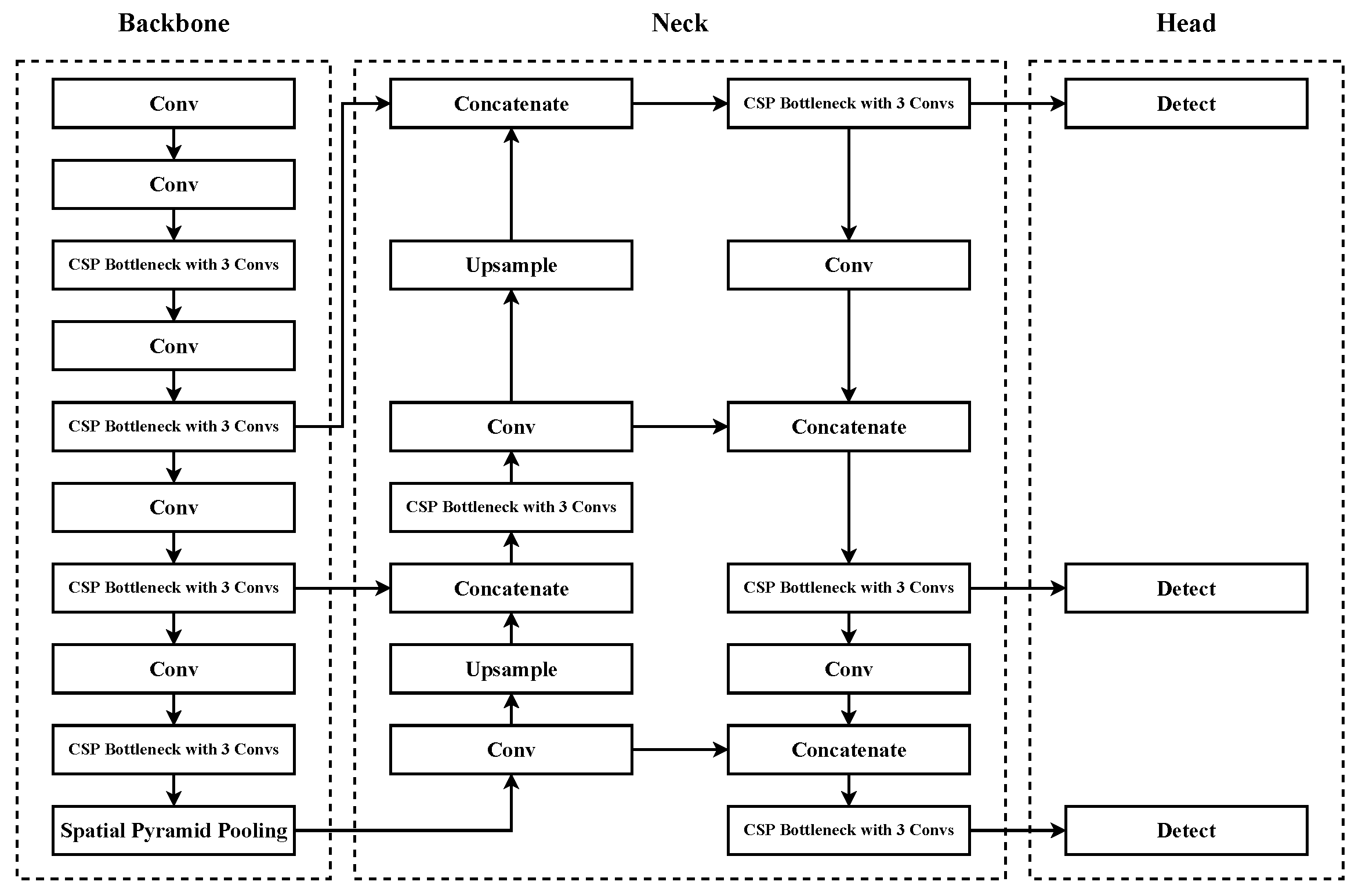
19]. YOLOv5 belongs to the one-stage algorithm, which makes it quick enough to detect an image, and uses many techniques to achieve high performance, such as data augmentation, and more advanced training strategies, etc. As shown in
Figure 5, it follows the structure of YOLOv3 and YOLOv4, which can be described as “Backbone-Neck-Head”. With this design, YOLOv5 can detect objects with high accuracy and speed. Meanwhile, YOLOv5 also uses depth and width multipliers to control the scale of its models, so these factors come in handy to manage the depth of the neural network.
Not only does it perform well, but YOLOv5 also supports PyTorch Hub, which is a model-sharing platform, and allows users to call or deploy a model in a short period of time with a few lines.
3.3.2. Locating the Position of a Vehicle
The detection results are a series of bounding boxes from vehicles. By applying IPM, the center of a bounding box can be transformed into virtual coordinates. As illustrated in
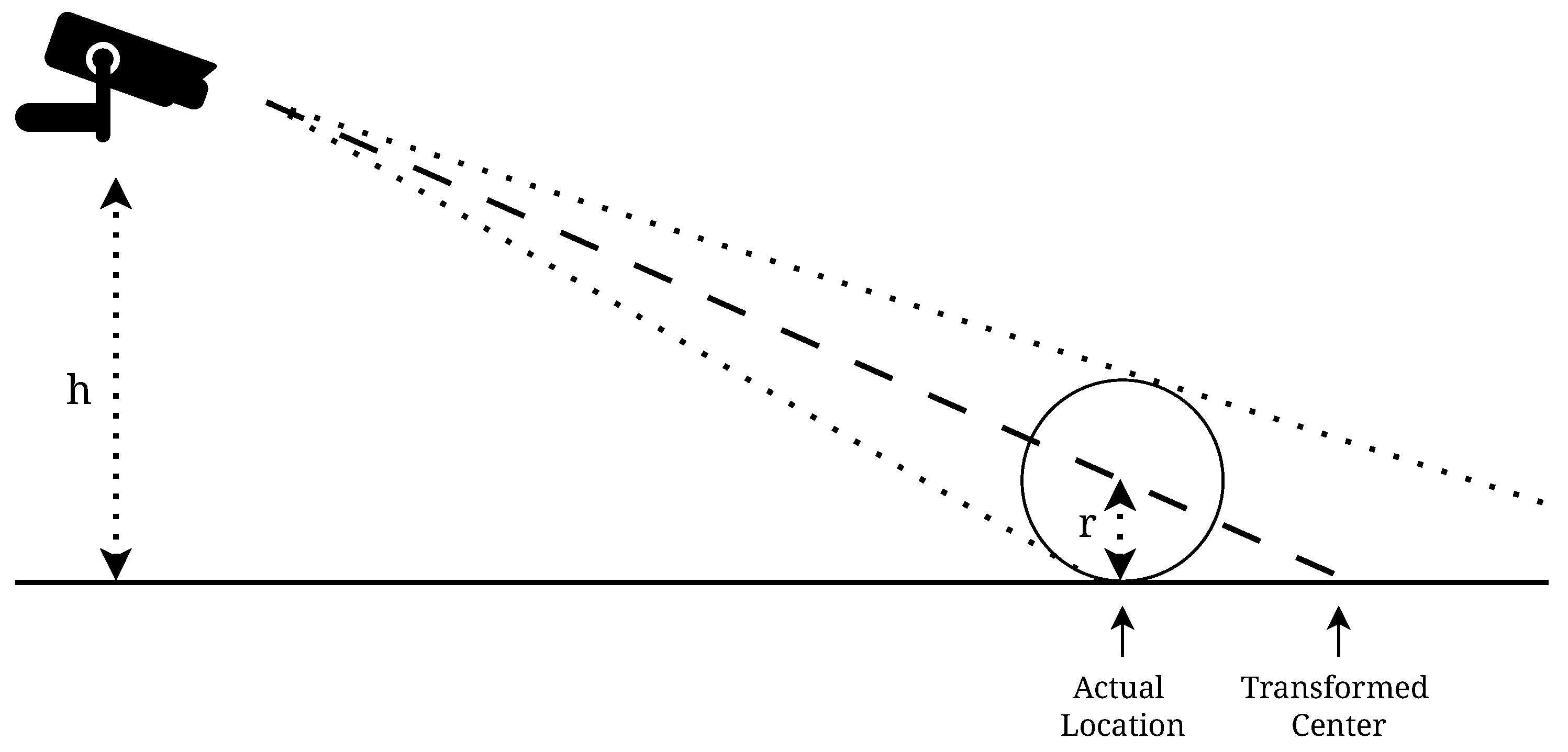
Figure 6, when the position of the box center is transformed, the transformed location is not the actual location of the vehicle. The position of the transformed center needs to be adjusted to the actual location as closely as possible. We simply model the detected vehicle as a circle.
h denotes the height of the camera and
r denotes the half height of the vehicle. The distance between the bottom and the actual location is denoted by
and the distance between the bottom and the transformed center is denoted by
. When the heights of the camera and the vehicle are known, the actual distance can be calculated as follows:
In the aerial view, the locations are denoted in points.
O denotes the location of the camera,
A denotes the actual location, and
C denotes the location of the transformed center.
A can be calculated by the following equation:
In the implementation, the height of the camera is known and we use the average height of vehicles as r. After the calculation, the difference between the calculated location and the ground truth is reduced. However, because vehicles and their poses are variable, the result may still not be accurate when the distance between the camera and the detected vehicle is too long. Similar to the fused aerial view image, we can assign a responsible area to each camera, i.e., for each camera; only the results located in this area (where the camera is the nearest one to every pixel inside) are accepted. In the case of a vehicle located on the border between two areas, which may lead to both results not being accepted, we set a tolerance. In detail, each pixel not only accepts the result from the nearest camera, but also the camera whose distance to this pixel is less than the nearest camera distance plus a predefined value.
3.3.3. Vehicle Tracking
The detected bounding boxes are not directly labeled to a certain vehicle. A tracking method should be used to track vehicles by their coordinates in a sequence of frames. An object tracking framework is provided in [
20]. It uses an object detector to find the bounding boxes of vehicles, then uses a Kalman filter to predict future bounding boxes and associate them with the vehicles. Our system uses this method to track the vehicles in the parking lot with some modifications. The bounding boxes were converted to coordinates in the previous section; therefore, the input and output of the Kalman filter are coordinates. In addition, due to the tolerance, a vehicle may be related to multiple coordinates. To associate these coordinates, when a new vehicle is detected by a camera (except for the vehicle located at the entrance), the system will associate it with the nearest coordinates.
3.4. Parking Space Management and Guidance System
When the parking lot is large and almost full, it is difficult for a user to find an available parking space, which is time consuming and frustrating. With the functions mentioned above, a parking space management and guidance system is proposed. This system applies those functions and guides the users to an available parking space.
3.4.1. Parking Space Allocation
In the previous sections, the coordinates of each parking space and vehicle were captured. Using this information, the system can determine the occupancy of a parking space. If a vehicle is located in the bounding box of a parking space, this parking space will be marked as occupied. The occupancy detection for parking spaces should be periodic in case some users do not use this system.
When a new vehicle enters the parking lot and uses this system to find a parking space, the system will allocate an available parking space to it, referring to the occupancy of parking spaces. The allocation strategy may vary considering the different situations or requirements of the parking lot. For example, the system can allocate the nearest parking space to a short-term parking user and allocate a parking space in a particular area to a long-term parking user. With the allocated parking space, the user can follow the guidance function to find it, which will be introduced in the following section.
3.4.2. Route Planning and Guiding
In this section, the processes of route planning and guiding will be introduced. Each parking space has a route for entering the parking lot and a route for exiting. When planning a route, we first update the graph for the departure and destination. Next, we utilize an algorithm to find the shortest path to the parking space. Once these two steps are completed, the guidance system can provide accurate guidance to the users and lead them to their destination.
Graph Updating: Before route planning, the origin and destination should be represented in the graph. Two temporal nodes are created upon a user requesting the guiding service: indicates the node for the target parking space, and indicates the node for the vehicle. is calculated by projecting the center of the allocated parking space to the nearest edge. is located at a predefined location where the user can access the system. Both of the two nodes are inserted into the target edge and connected to the vertices on that edge. The new edge follows the direction of the target edge.
Route Planning: Route planning is the shortest path problem because the system should use the shortest possible distance to guide the user towards the location. There are a lot of choices for the shortest path problem, i.e., Dijkstra [
21], Bellman-Ford [
22], A* algorithms [
23], etc. Dijkstra is a simple but powerful and popular algorithm with many good solutions [
24,
25]. It is the most suitable algorithm for this system to carry out route planning. The process of applying the Dijkstra algorithm to route planning can be briefly described in the following steps:
Initialize the graph with the origin node and destination. Here, the directed graph created in
Section 3.2.2 can be used.
Create the Shortest Set and Unvisited Set. Assume S as the Shortest Set, and add the to this set. Meanwhile, add other nodes to the Unvisited Set (U) and set their distance to infinity.
Find the nodes that connect a node in S, then calculate their distance. Update the distance if it is smaller than before; otherwise, maintain the original. Among these nodes, add the node with the minimum distance to S and record the shortest path.
Repeat step 2 and 3 until the is added to the S. The path recorded is the shortest.
In our system, the guidance function is requested when a user enters or leaves the parking space. Therefore, for each parking space, the route from the entrance to the parking space and the route from the parking space to the exit can be calculated and stored in advance. When the guidance function is requested, the corresponding route can be called directly, which saves processing time.
Workflow of Guidance System: When requesting guidance services, the user should access the guidance system through methods such as scanning the QR code or using a mobile application. If the user is at the entrance, the system will locate the vehicle at the entrance. If the user is in a parking space, the user can be located through a method such as inputting the identification number of the parking space, scanning the QR code corresponding to the parking space, or using the guidance information when entering the parking lot. The path consists of a sequence of nodes that the user is expected to follow. At first, the user is considered to be located at the first edge, which is represented by the first two nodes in the path. The system tracks the position of the user to provide further direction by repeating the following steps:
The system calculates the distance of the vehicle and the current edge to ensure it is following the guidance.
The system calculates the projection of the vehicle coordinates on the edge to obtain the position on the graph.
According to the path, the direction to the next node is returned to the user.
This process ends when the user reaches the target position or does not follow the guidance. After guidance ends, the occupancy detection will be called to update the occupancy status of the parking spaces.
4. System Simulation
In this section, we will discuss the result of simulating the processes of system operations through 3D software. We implemented the functions in the system through Python and its OpenCV library. We used YOLOv5 based on PyTorch as our object detector. We used a 3D model of a parking lot using Unity3D. The structure of this model is similar to the north parking lot of Macao International Airport. It consists of 119 parking spaces, 6 cameras, and other infrastructure. The heights of the cameras are the same, but the poses are manually adjusted to cover the whole parking lot and to simulate manual installation.
Figure 7 shows the aerial view of the model and camera views of the six cameras. The positions, directions, and approximate fields of view are illustrated in
Figure 7d. Note that the cameras are adjusted to ensure that every parking space is covered by at least one camera.
4.1. Parking Lot Coordinate Mapping
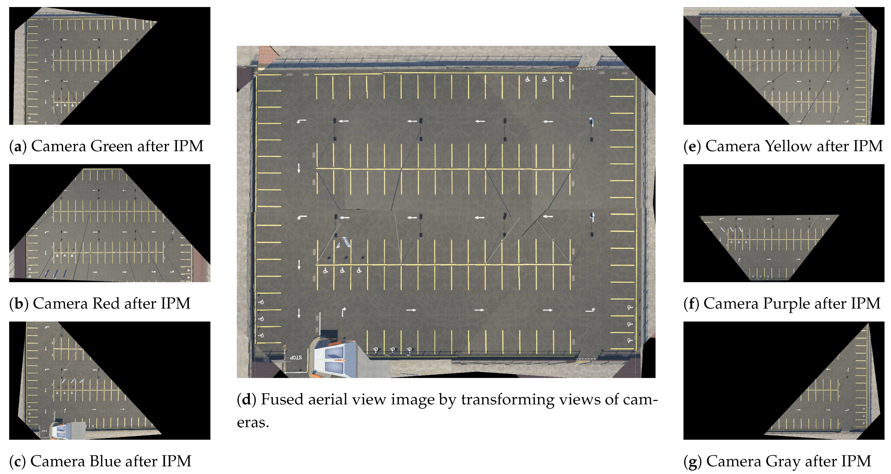
For each camera, we choose four points (which are basically ends of lines or line–line intersections) as marks. Then, we find the pixel coordinates of the marks and calculate virtual coordinates. Note that the quadrilateral formed by the four points in a camera view should be as large as possible to reduce the deviation. By applying IPM, we can obtain the perspective transformation matrices, which contain the relationships between the camera views and aerial views of the cameras. The transformed views of cameras are shown in
Figure 8a–g.
Then, we build a camera lookup table, which records the distances and orders of distance from all cameras for each pixel in aerial view. For example, the value in the table for the pixel in the top-left corner stores an array:
. The array contains the colors of the cameras and the nearer camera has a smaller index. With this lookup table, a fused aerial view image can be generated. For each pixel, it copies the color of the transformed view of the nearest camera. If that camera does not cover this pixel, it will find the next nearest camera. The generated image is shown in
Figure 8d.
4.2. Parking Lot Modeling
We use the fused aerial view image generated in the previous section to extract parking spaces. The process follows the steps mentioned in
Section 3.2.1.
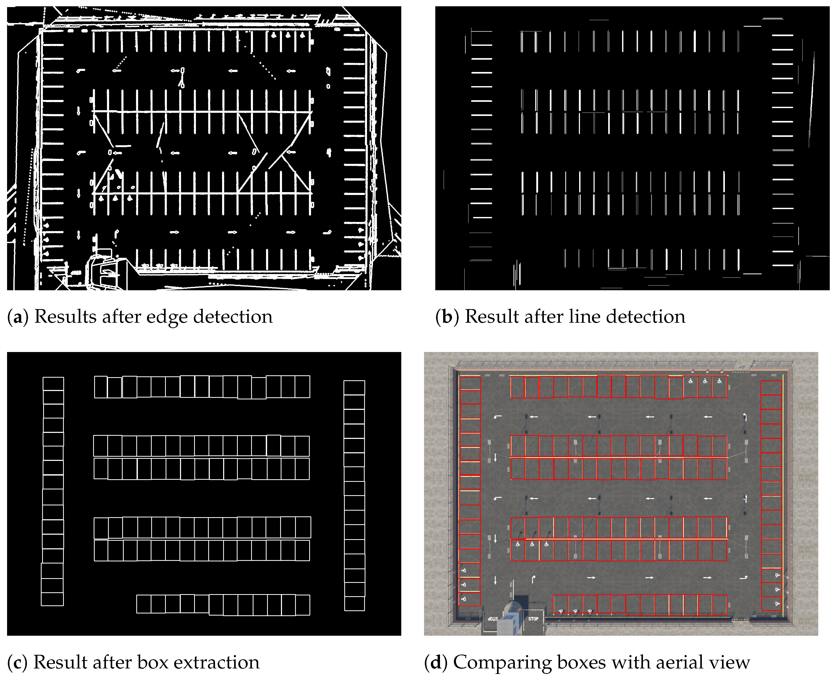
Figure 9a–c show the result of each step in parking space extraction.
In the parameter settings, the number of kernels for the blur operation is 4, the thresholds for the Canny edge detector are 150 and 250, the pixels at the edges dilate by 1 pixel in four directions, and the threshold for the Hough transformation is 50.
We first blur the fused aerial view image. Then, we apply Canny edge detection to the image and dilate it. The result is shown in
Figure 9a. Next, we detect the lines in the result and filter the lines by their direction and length. Because the parking spaces in the model have horizontal and vertical alignments, the lines perpendicular to these two directions are retained. When filtering lines by length, we set a tolerance on length to prevent incorrect filtering. The detected lines are shown in
Figure 9b. Then, the lines are divided into two groups according to their direction and the boxes are extracted from them. The extracted boxes are shown in
Figure 9c. The comparison of extracted boxes with the real aerial view is shown in
Figure 9d. The comparison shows that every parking space is extracted and basically covered by its box.
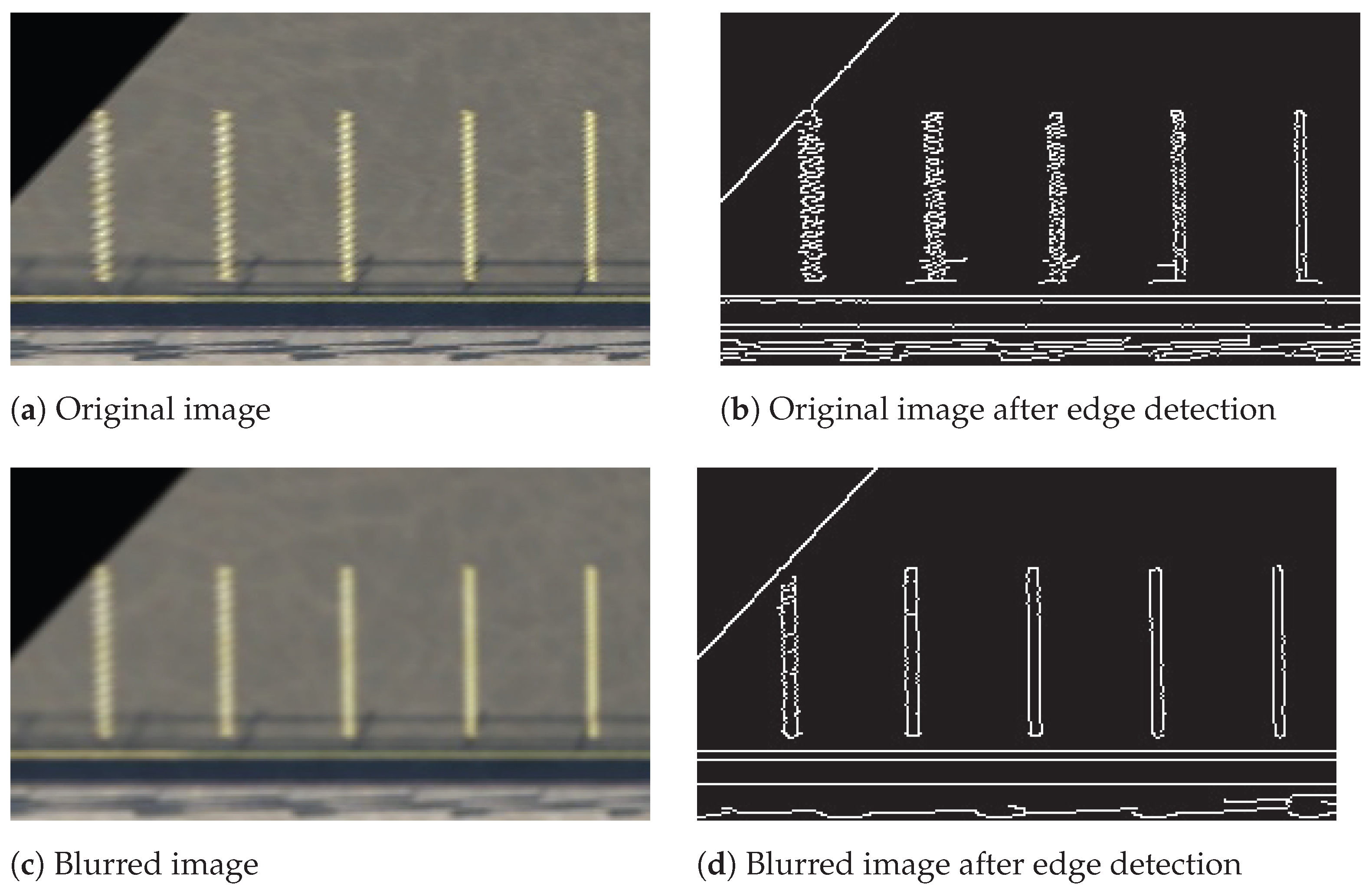
In this simulation, the parking spaces far from the camera did not encounter too much distortion because the resolution of the images was high.
Figure 10 shows a downsampled example. This example was originally located at the bottom of the transformed view of Camera Gray (
Figure 8g). The example image was downsampled to 50% of its original size, and the result of edge detection for the original downsampled image was disordered. For the blurred image, we use 50 and 200 as the Canny thresholds. The edges detected from the blurred image are much clearer.
As described in
Section 3.2.2, a directed graph is used as a routing model to help the system collect route information easily. The routing model is a graph consisting of the following components:
V, the vertices set will include the entrance and exit.
E, the edges set will be unilateral due to the guidance of the arrows in the parking lot.
Figure 11 illustrates the graph representing the routes in the parking lot. The weight of each edge is shown. The weight is the distance between two vertices in thousands of pixels.
4.3. Vehicle Detection and Locating
To simulate a normal situation in a parking lot, we randomly put some vehicles in the model. PyTorch Hub is used to deploy YOLOv5. After detecting vehicles on each camera view, the center of each bounding box is extracted. As mentioned in
Section 3.3.2, the centers will be transformed to the virtual coordinates with adjustments. Measured in the software, the height of each camera is 5.75 and the average height of vehicles is 0.75. The tolerance of accepting results is set to 200 pixels. The camera lookup table generated in
Section 4.1 is used with the tolerance to filter the results. After applying the perspective transformation matrices produced in
Section 4.1 and the steps in
Section 3.3.2, the results are illustrated in
Figure 12. A circle in the figure shows a detected vehicle and its color indicates the camera that detects this vehicle. The line connects the detected vehicle and the detecting camera. In this case, all the vehicles in the model are successfully detected and their calculated locations basically cover their models.
Based on this model, we designed an experiment to evaluate the accuracy of vehicle detection and location. We developed a script to randomly place 5 to 15 vehicles on this parking lot and used it to generate scenes for the experiment. For each scene, we used the script to randomly place vehicles. Furthermore, the images of the six cameras and the coordinates of the placed vehicles were collected. We collected data for 100 randomly generated scenes, where 977 vehicles were placed in total. For the collected images, we used the proposed method to convert them into the located points. For the coordinates of placed vehicles, we transformed them into the virtual coordinates, i.e., the pixel coordinates in the aerial view. If a vehicle was close to a located point and the distance was less than 30 pixels, we considered it as located. Otherwise, it was considered missing. Note that the average length of the vehicles in the aerial view was around 60 pixels. In addition, if a vehicle was close to points from multiple cameras, we used the mean of the points as the located point.
Two metrics are used to evaluate the method. The first is accuracy:
where
denotes the total number of vehicles, and
denotes the number of successfully located vehicles. The second is mean distance error:
where
denotes the coordinates of the point located by the cameras,
is the actual coordinates, and
is the L2-norm calculating the distance between
and
.
Table 1 shows the evaluation results. In total, 948 out of 977 vehicles were successfully detected. The accuracy of the experiment is 97.03%. The mean distance error is 8.59 pixels. Because the average length of a vehicle is around 60 pixels and the average width is around 25 pixels, this distance error is acceptable.
4.4. Guidance
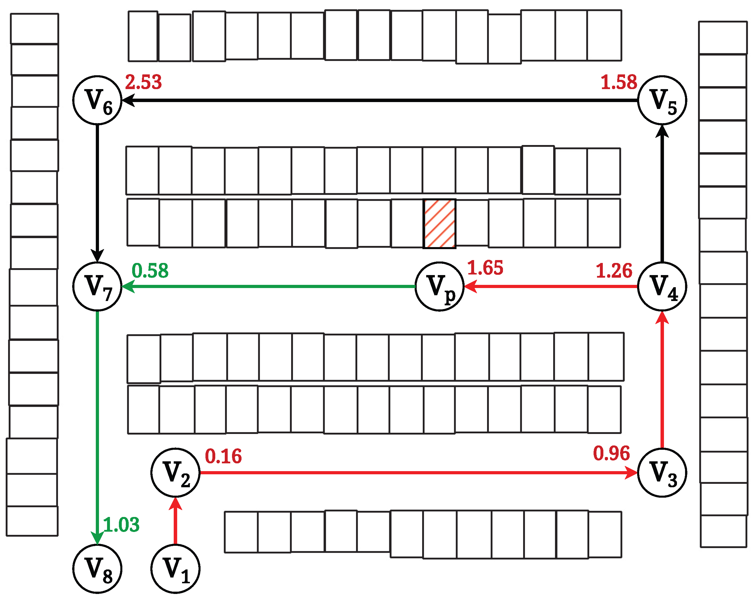
In the simulation for the guidance system, we assumed that a vehicle enters the parking lot and requests guiding service at
. The system randomly allocates a parking space to the vehicle, which is the bounding box with red hatching as illustrated in
Figure 13.
The process of calculating paths for this parking space follows the steps in
Section 3.4.2. The system projects the location of the allocated parking space to the nearest edge and adds a temporal node as the destination. The new node is located on the edge
. The weight of the new edge
is calculated to be
, and the weight of
is
. Then, the Dijkstra algorithm is applied. As shown in
Figure 13, until the shortest distance of
is added, the distance of the reached nodes is shown next to the node. The shortest path to the parking space is
. The shortest path to the exit is
. The system follows this path to guide the vehicle until it reaches
. When the vehicle is going to leave the parking lot, the system will guide it, following the path from
to
.
5. Discussion
The proposed system boasts significant advantages, such as its simplicity and ease of installation. It has been designed as a plug-and-play solution that can be easily deployed in most situations with cameras that can be installed. Additionally, the system has adopted many mature algorithms used in the corresponding field, which provide many solutions to troubleshooting maintenance problems. However, similar to our simulation results in the parking lot of Macao International Airport, to optimize the system’s performance, certain limitations must be addressed.
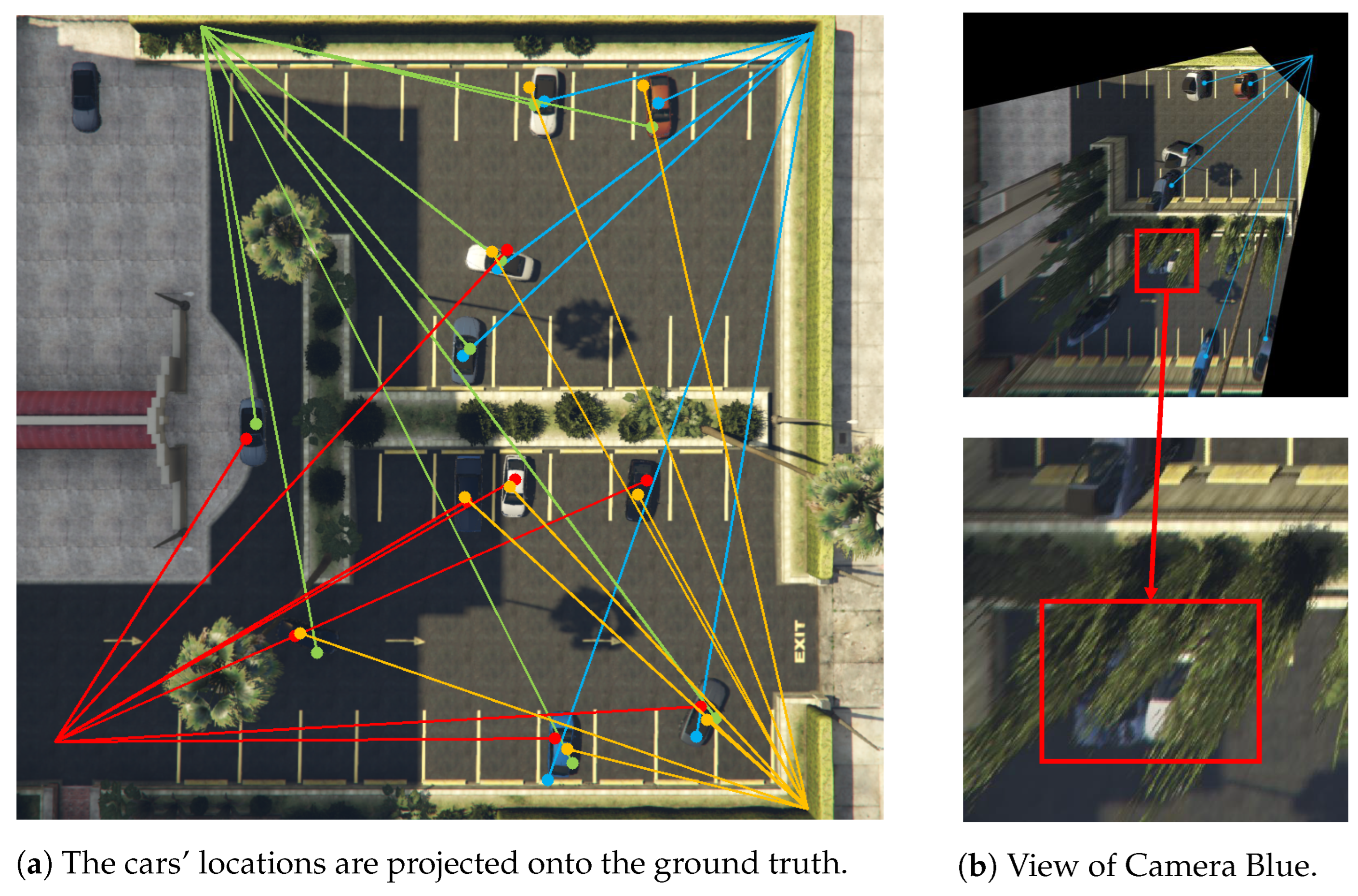
Another evaluation of our proposed location method in a different parking lot is illustrated in
Figure 14. We encountered some challenges in detecting vehicles due to blockages caused by plants, as indicated by
Figure 14b. For our proposed location method, the accuracy of the system is sensitive to such blockages and can affect the overall performance. To address this, it is important to note that the pose and position of the cameras need to be carefully designed to ensure optimal performance in challenging environments.
Meanwhile, our proposed methods require precise information from the parking lot. In the simulations, we took extensive measures to ensure the precision of data to improve the performance of the functions. For instance, if the data are not precise enough, the parking space extraction process may not be able to generate a complete parking space map, because the lines crossing two responsible areas may be broken. Furthermore, bad coordinate mapping may cause bad accuracy in locating vehicles. In addition, the coordinate transformation model is relatively simple, and a more generalized transformation method can reduce the estimated distance error in different scenarios.
In the guidance system, we currently use pre-calculated routes to guide users. However, when there are too many users on the route, congestion inside the parking lot may occur, and the pre-calculated routes cannot handle the congestion. A possible solution is to recalculate the shortest route when there are too many vehicles detected on the pre-calculated route. The weight of an edge should be updated according to the number of vehicles detected on that edge.
In our paper, we assumed limited types of vehicles commonly found in parking lots for convenience. However, as discussed in
Section 3.3.2, the coordinates of the detected bounding box need to be transformed before estimating its real coordinates. Here, we calculated them using one set of transformation parameters (average height, etc.), which only fit the limited types of vehicles we considered. This means that the set of parameters may not be suitable for other types of vehicles. A possible solution is to generalize the model by fine-tuning YOLOv5, which was originally trained on the COCO dataset, and updating our parameters in coordinate transformation to account for different types of vehicles and scenarios, such as buses or trucks. By doing so, we can improve the performance of our system and make it more adaptable to various scenarios.
6. Conclusions and Future Work
In this paper, we present a cutting-edge camera-based smart parking system that leverages perspective transformation. Our system goes beyond the traditional use of cameras for security purposes and utilizes them as data collectors to provide location and tracking information for vehicles. By optimizing inverse perspective mapping (IPM), we fuse frames from different cameras to create an aerial view image that facilitates parking space extraction and route modeling. The collected data were processed and analyzed using a variety of tools, including YOLOv5.
To evaluate our system’s performance, we conducted tests on a 3D model of the Macao International Airport parking lot. We installed six cameras at various angles and heights to capture the entire lot, and the system was able to produce highly accurate and valuable information, resulting in increased efficiency. For vehicle detection and location, our system also works well with an accuracy rate of 97.03% and a mean distance error of 8.59 pixels.
However, our system has some limitations that need to be addressed, such as the need for precise data for effective parking lot modeling and sensitivity to occlusions in camera frames. Nevertheless, our camera-based smart parking system, which utilizes IPM, object detection, and a guidance system with multiple cameras, has tremendous potential for enhancing the parking experience for users, and improving profitability and management efficiency for airport managers. Our unique contributions, such as the use of perspective transformation and aerial view images for parking space extraction and route modeling, have significant potential for advancing smart city development.
By highlighting the significance of our novel techniques, we aim to demonstrate the value and potential impact of our research on the field of smart parking systems. Going forward, we plan to deploy our system in the Macao International Airport parking lot to further increase efficiency and support Macao’s smart city development.


