Article

Power Quality Analysis by H-Bridge DSTATCOM Control by Icosθ and ESRF SOGI-FLL Methods for Different Industrial Loads

1
Department of Electrical and Electronics Engineering, National Institute of Technology Sikkim, Ravangla 737139, India
2
Department of Railroad and Electrical Engineering, Woosong University, Jayang-dong, Dong-gu, Daejeon 34606, Republic of Korea
*
Author to whom correspondence should be addressed.
Smart Cities 2022, 5(4), 1590-1610; https://doi.org/10.3390/smartcities5040081
Submission received: 16 October 2022 / Revised: 9 November 2022 / Accepted: 14 November 2022 / Published: 17 November 2022

Abstract

:
This work develops the analysis of power quality by the H-bridge Static Distribution Compensator (DSTATCOM) as well as its control techniques in different industry-based loading conditions. The function of DSTATCOM is to diminish power quality problems arising due to commercial as well as industrial loads. For reference current extraction, the novel Icosθ and proposed enhanced SRF SOGI-FLL (synchronous reference frame second-order generalized integrator frequency-locked loop) controller have been adopted in the H-bridge DSTATCOM. The Icosθ controller’s performance is dependent on the in-phase and quadrature-phase angle, which changes accordingly as load changes, whereas the proposed enhanced SRF SOGI-FLL controller works in synchronization with the grid with an inverter. The two control techniques were compared in terms of balancing, power factor improvement, DC-link voltage control, and harmonic minimization. The harmonics minimization of the proposed controller has been validated by IEEE 519 standards. The extracted reference currents are fed to the hysteresis current controller for the generation of pulses toward the inverter switches of DSTATCOM. The DSTATCOM system along with control algorithms have been tested on various loading conditions, i.e., voltage source- and current source-based non-linear loads, induction heating-based loads, and electric arc furnace. The complete DSTATCOM systems were implemented and executed in the MATLAB/Simulink platform and then power quality improvement features were investigated.

1. Introduction

Today, non-linear loads based on power electronics are intrinsically used in AC power systems [1]. These loads represent non-linear characteristics of a time-varying nature and draw non-sinusoidal current from the grid, which results in the deterioration of the superiority of the power in the AC supply [2]. In the current situation, continuity and quality of electricity supply are critical because we rely heavily on electricity and its applications [3]. Many loads utilized for industrial [4], commercial [5], and domestic [6] reasons are made up of power electronic gadgets. Some examples of power electronics appliances based on non-linear loads are computers [7], induction furnaces, electric arc furnaces, EV chargers [8], traction systems [9], drive systems [10], etc. These loads create power quality problems in the AC distribution system. There are two types of power quality issues: voltage quality and current quality [11]. The DSTATCOM is one of several shunt-connected custom power devices that are employed in the supply structure to mitigate current quality problems [12].
In addition, when excess current flows through the neutral line of a three-phase four-wire (3P4W) structure due to unequal loads, this situation worsens [13]. Performances of DSTATCOM topologies in the 3P4W structures have been proposed in the literature [14]. The multilevel converter topologies discussed in the literature [15] have smaller losses, reduced filter size, and higher efficiency than conventional two-tier voltage source converters. However, they are expensive. The functioning of these topologies is based on the number of switches and their switching strategies. In this paper, H-bridge-based multilevel converter topology has been employed in DSTATCOM. In the last few decades, several researchers have focused on building up the efficient and robust control of DSTATCOM. To ensure control of the DSTATCOM, a number of control strategies have been discussed in the literature [16]. Phase-locked loop (PLL) in the SRF control technique synchronizes the grid frequency with the power inverter, but the major drawback of PLLs is their implementation in digital circuits, larger computational time, less efficiency to correct distortion of voltage profile, voltage frequency variation, etc. [17]. The literature [18] offers independent and enhanced DC voltage control capable of managing the insulated capacitors of an asymmetric converter. The design and functioning of DSTATCOM’s robust control, i.e., sliding mode control (SMC) to adjust for voltage sag phenomena, were explained in [19]. The incorporation of electric vehicles (EVs) into the distribution system has an impact on power quality issues. This can be avoided by employing the neural fuzzy control technique [20]. This research presents a unique three-phase harmonic power flow (HPFA) algorithm for unbalanced radial distribution (URDN) networks with linear and non-linear loadings and the integration of a DSTATCOM device [21]. The recommended mitigation strategy has been incorporated in the distribution of static compensators, which successfully reduce light flickers regardless of whether the fast charging station’s output power is estimated or actual [22]. A non-linear MINLP (Mixed Integer Programming) model is used to solve the problem of optimal regulation of the reactive power stream [23]. Reference [24] discussed a unique control strategy for improving power quality using an artificial neural network (ANN)-based distribution static compensator. The conventional proportional-integral (PI) controller is replaced with a novel online-trained wavelet Takagi–Sugeno–Kang fuzzy neural network (WTSKFNN) controller to improve the transient responses of grid currents and DC-link voltage control, as well as the performance of the DSTATCOM [25]. Incorporating DSTATCOM into the distribution system provides harmonic compensation, load balancing, and neutral current compensation [26]. The main difficulty of sliding mode control is to design the sliding surface in the dynamic system. If the surface design is not appropriate in dynamic conditions, it will give an unacceptable performance.
In this article, SRF control is used without PLL, and, for signal synchronization, SOGI-FLL is used. Less computational time, less complexity, and the minimum time requirement to synchronize the frequency and phase angle of the grid with a power inverter are the key advantages of SOGI-FLL as compared to other conventional controllers.
Hence, in this paper, the proposed enhanced SRF SOGI-FLL [27] and Icosθ controller [28] have been employed in the H-bridge DSTATCOM and performances have been compared under both control techniques. This paper has been organized into different sections. Section 1 covers the introduction of this paper. Section 2 elaborates on the circuit configuration of the H-bridge VSI-based DSTATCOM. Section 3 illustrates control methods adopted in the H-bridge DSTATCOM. Section 4 contains discussions of various types of non-linear loads employed in the distribution networks. Section 5 illustrates the discussion of results under various loading conditions. The last Section 6 is the conclusion of this paper.

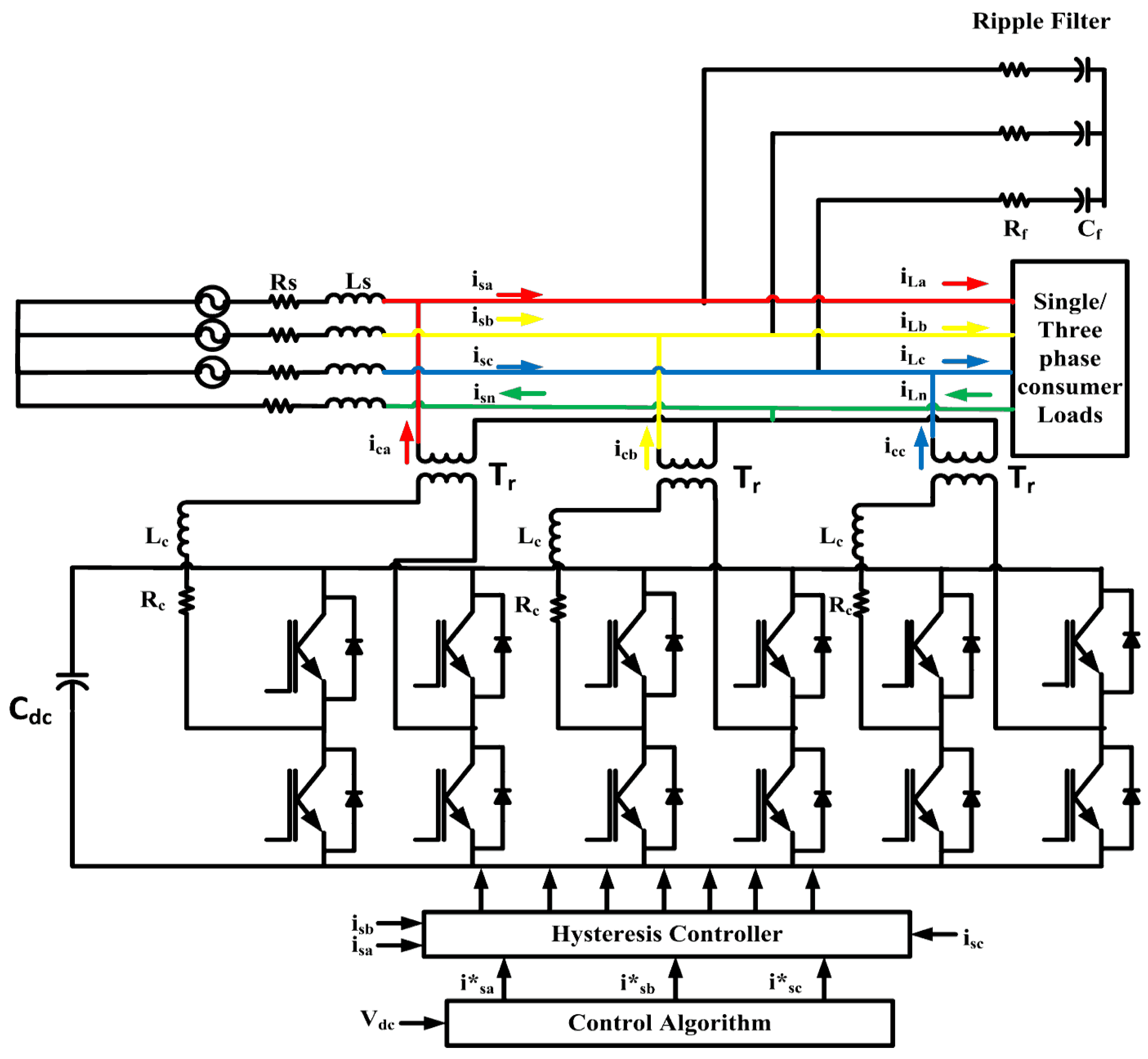
2. Distribution Static Compensator (DSTATCOM)

To alleviate the current quality issue in the supply structure, DSTATCOM is adopted as a customized power supply device [29]. It also alleviates the odd and even harmonics of the grid current, which are generated due to the existence of non-linear loads. DSTATCOM comprises a voltage source inverter (VSI) having 12 IGBT/antiparallel diode switches, a DC capacitor, and an interfacing inductor L f   for minimizing the ripples [30].
Figure 1 shows the circuit arrangement of three H-bridge DSTATCOMs bonded to a 3P4W structure feeding a non-linear load. In this figure, I s a ,     I s b , and I s c represent the source current of three-phase AC mains, respectively. I L a ,   I L b , and   I L c represent the three-phase load currents. Resistance and inductance of the three-phase supply are R s and L s , correspondingly. I c   and V c denote the injecting current and DSTATCOM voltage. L f   is an interfacing inductor connected at the AC side of the voltage source inverter. V d c   is the internal voltage of the DC-link capacitor. The ripple filter is modeled as R f and C f   , which are attached at the PCC. In this article, the control algorithms of the proposed enhanced SRF SOGI-FLL and Icosθ controller have been selected. The task of the hysteresis controller is to give out gate pulses for VSI switches.

3. Control Algorithms

The key point of the DSTATCOM control algorithms is to compute the reference currents by means of feedback signals [31]. These reference currents and corresponding sensed currents are fed to hysteresis controllers to achieve PWM gating signals for switching devices (IGBTs) of the VSI employed as a DSTATCOM [32]. The control algorithms proposed in this paper are enhanced SRF SOGI-FLL and Icosθ controllers, which are discussed below:

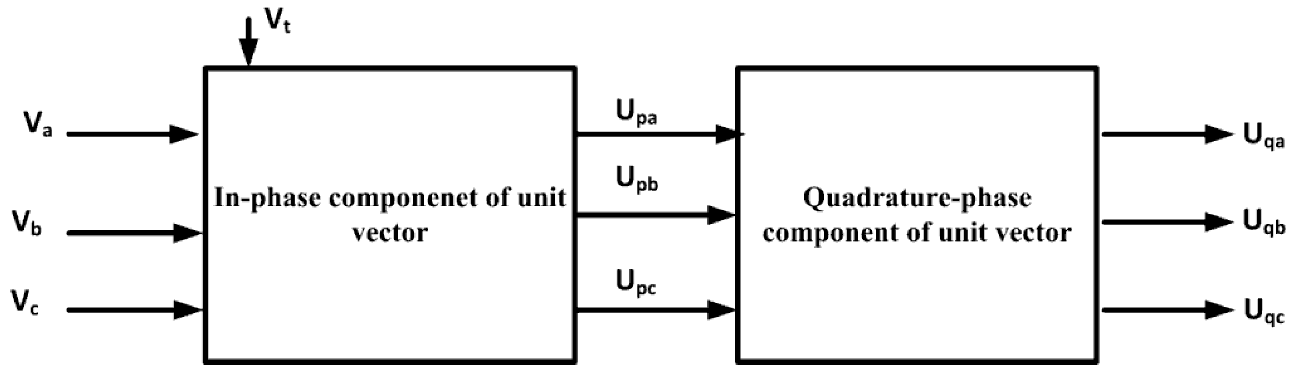
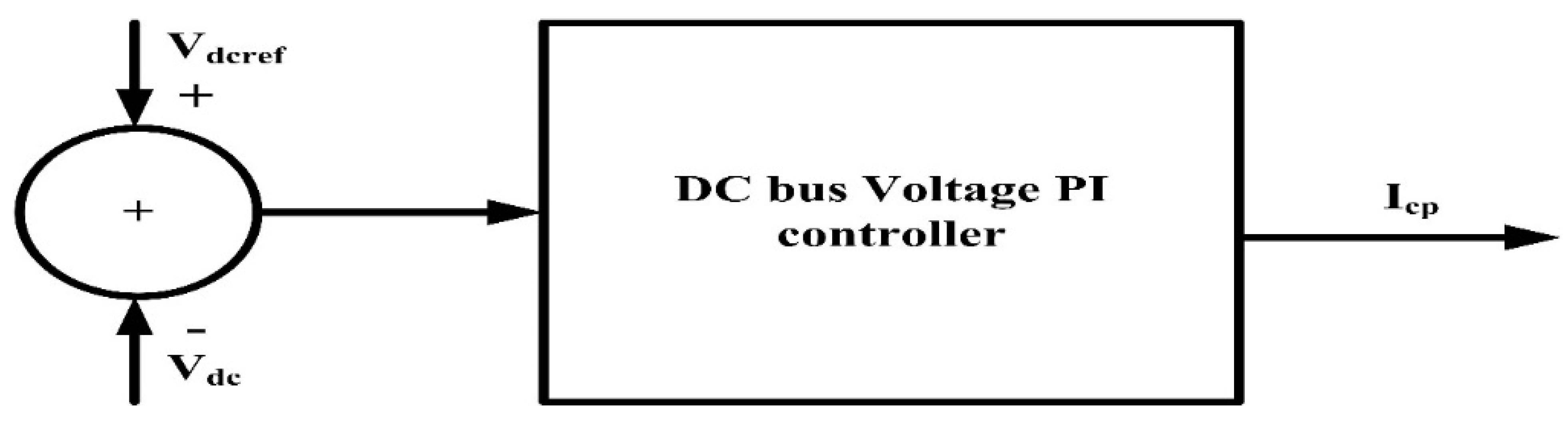
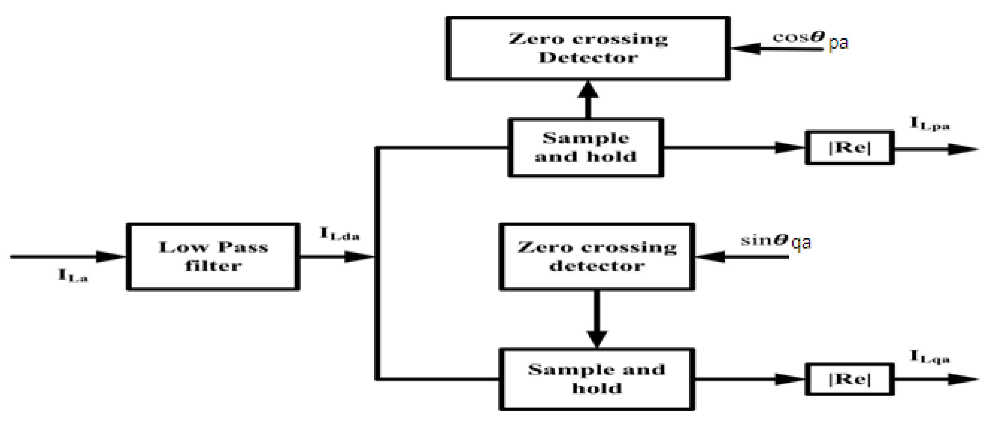
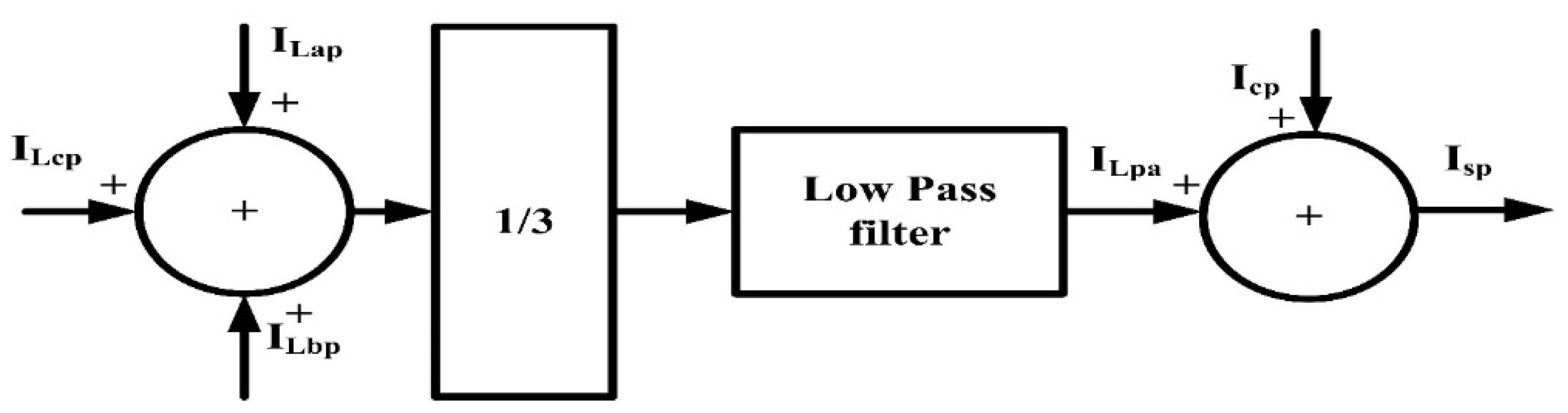
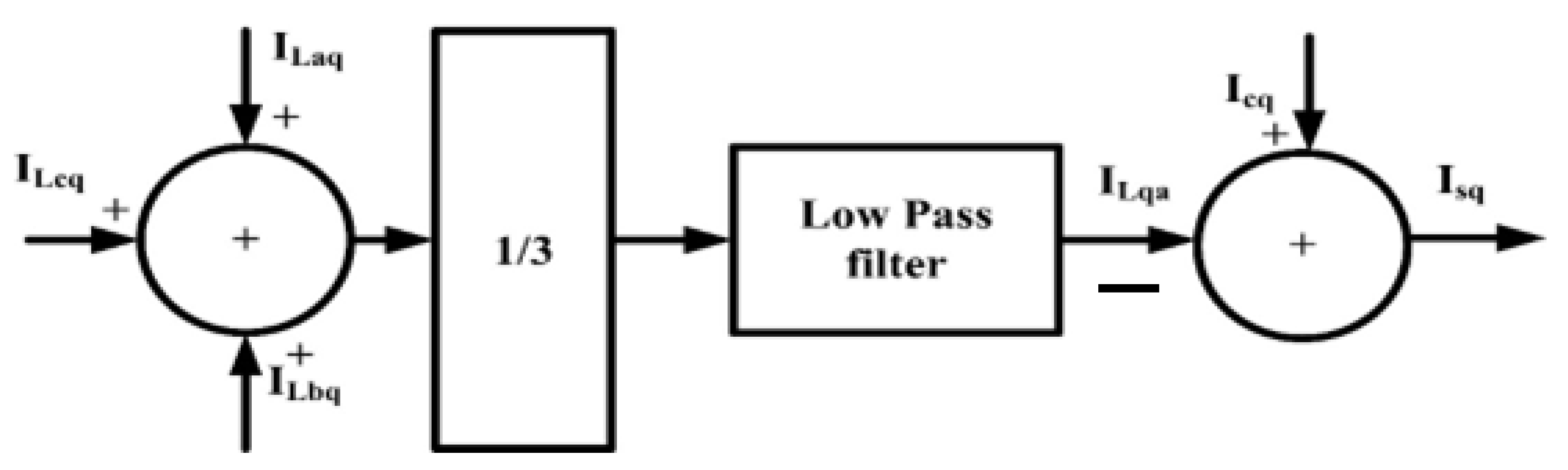
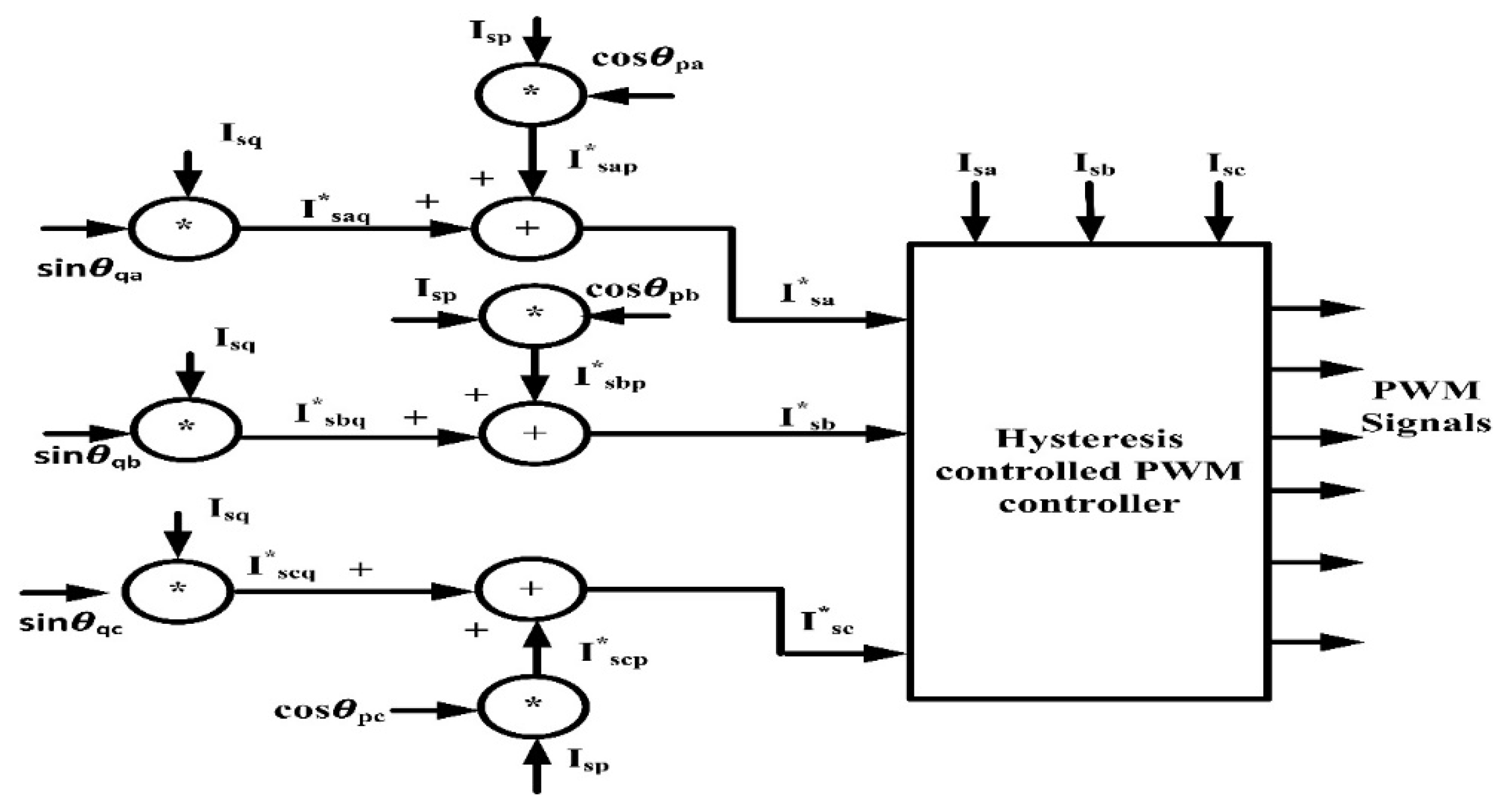
3.1. Icosθ Controller

Step 1: Calculation of in-phase and quadrature-phase components of the unit vector
V a , V b ,   a n d   V c are the three-phase points of common coupling (PCC) voltage. The amplitude of the terminal voltage V t   is obtained from these PCC voltages as shown in in Figure 2.
V t = 2 V a 2 + V b 2 + V c 2 3
In-phase component of the unit vector:
U a p = V a V t = cos θ p a ,   U b p = V b V t = cos θ p b ,     U c p = V c V t = cos θ p c
Quadrature-phase component of the unit vector:
U a q = ( U b p + U c p ) 3 = sin θ q a
U b q = ( U a p 3 + U b p U c p ) 2 = sin θ q b
U c q = ( U a p 3 + U b p U c p ) 2 = sin θ q c
Step 2: Calculation of I_cp, which is a part of the d-axis component
The Figure 3 represents the design of I_cp.
V d c e ( k ) = V d c r e f ( k ) V d c
I c p = k p d { V d c e ( k ) V d c e ( k 1 ) } + k i d V d c e ( k )
In the DC bus, proportional and integral constants are kpd and kid, respectively.
Step 3: Calculation of I_cq, which is the part of the q-axis component
The Figure 4 represents the design of I_cp.
V t e ( k ) = V t r e f V t
I c q = k p a { V t e ( k ) V t e ( k 1 ) } + k i a V t e ( k )
For AC voltage controllers, proportional and integral constants are k p a and k i a , respectively.
Step 4: Computation of the d-axis and q-axis part of the three-phase load current
The Figure 5 represents the design of I L p a and I L q a .The magnitude of the real power and reactive power parts of the load current of phase “a” is extorted from the fundamental component of the load current I L d a (achieved after filtering through a low-pass filter) on the zero crossing of the p-phase and q-phase unit template of the PCC voltage ( cos θ p a and sin θ q a ). A zero-crossing detector and “sample and hold” logic have been employed to extort I L p a and I L q a . Similarly, the amplitudes of the active power and imaginary power parts of currents for line “b” and line “c” can be estimated.
Step 5: Calculation of amplitude of the d-axis component of load current
The Figure 6 represents the design of amplitude of d-axis load current.
The magnitude of the real power part of the load current I L p a :
I L p a = { I L a p + I L b p + I L c p } / 3
The real power part of load currents in the a-b-c frame is I L a p , I L b p , and I L c p .
The amplitude of the d-axis component of the load current:
I s p = I L p a + I c p
Step 6: Calculation of amplitude of q-axis component of load current
The Figure 7 represents the design of amplitude of q-axis load current.
The amplitude of the reactive power component of the load current:
I L q a = { I L a q + I L b q + I L c q } / 3
The imaginary power part of load currents in the a-b-c frame are I L a q , I L b q , and I L c q .
The amplitude of the q-axis component of the load current:
I s q = I c q I L q a
Step 7: Generation of gate pulses
Active-phase parts of reference source currents have been computed as
I s a p = I s p cos θ p a
I s b p = I s p cos θ p b
I s c p = I s p cos θ p c
Quadrature-phase parts of reference source currents have been computed as
I s a q = I s q sin θ q a
I s b q = I s q sin θ q b
I s c q = I s q sin θ q c
Net reference three-phase supply currents are the addition of active-phase and q- phase reference supply currents:
I s a = I s a p + I s a q
I s b = I s b p + I s b q
I s c = I s c p + I s c q
These calculated reference supply currents ( I s a , I s b ,   I s c )   and the actual supply currents ( I s a , I s b ,   I s c ) produce a gating pulse width modulation (PWM) signal as shown in Figure 8.

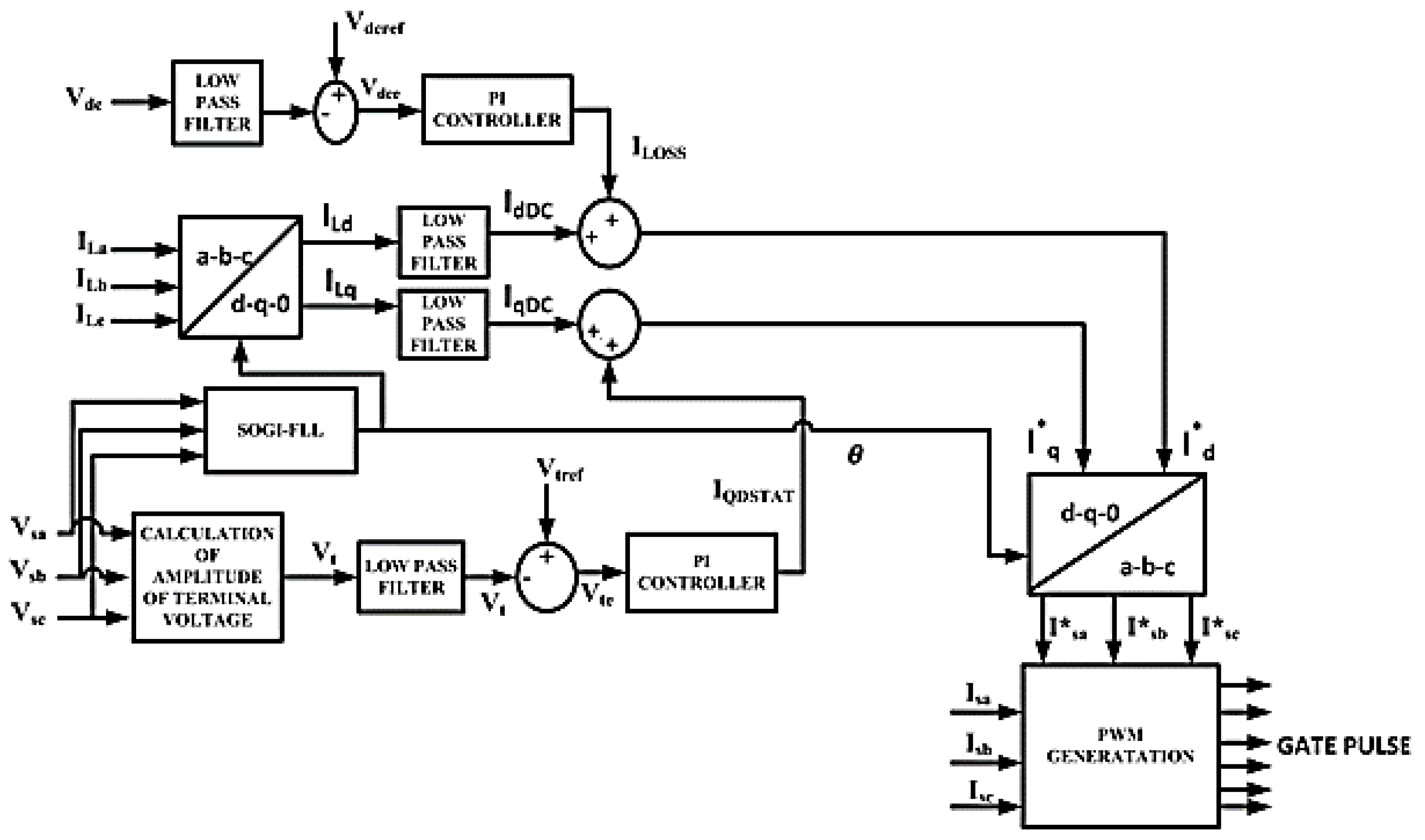
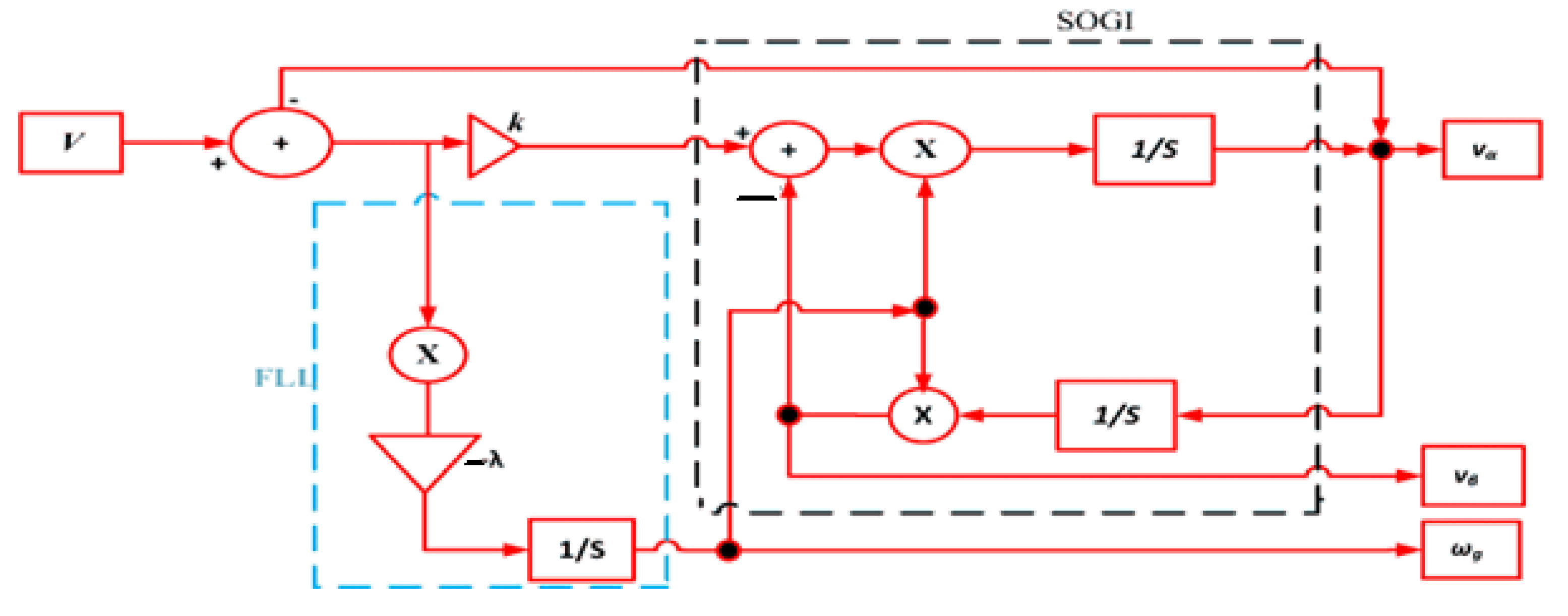
3.2. Enhanced SRF SOGI-FLL

Figure 9 represents the Enhanced SRF SOGI-FLL controller. In this novel control algorithm, conventional PLL has been replaced by SOGI-FLL [33]. SOGI-FLL has a faster response, less computational time, and better response in eliminating power quality issues present in the non-ideal grid. Here, mathematical modeling of the controller has been designed.
Figure 10 shows the block diagram of SOGI-FLL. v α is the single-phase input signal. v α ^ and v β ^ are the real and imaginary parts of the input signal v α , respectively. The input signal’s magnitude, frequency, and phase are v ^ , ω g , and θ respectively. The value of gains for SOGI and FLL are K and λ , respectively. The output signal of the SOGI-FLL is represented by v α ( s ) and v β ( s ) .
v α ^ ( s ) = K ω g ^ s S 2 + K ω g ^ s + ω ^ g 2 s v ( s )
v β ^ ( s ) = K ω g 2 ^ S 2 + K ω g ^ s + ω ^ g 2 s v ( s )
Figure 11 and Figure 12 show the frequency response of v α ^ ( s ) and v β ^ ( s ) for different values of k, respectively.

3.2.1. Dynamics of SOGI-FLL

Initially, taking the supply voltage V s free from harmonic distortion:
v ( t ) = v α ( t ) = v cos ( ω g t + φ )
We take ω g t + φ = θ .
The output of the SOGI for the d-axis and q-axis becomes:
v α ^ ( t ) = V ^ cos θ ^
v β ^ ( t ) = V ^ sin θ ^

3.2.2. Mathematical Modeling of Standard SOGI-FLL

v ^ and θ ^ are the amplitude and phase angle of the input supply voltage, respectively. Assuming SOGI-FLL is in a quasi-locked state, v ^ v and θ ^ θ   ( extremely close values of v   and   θ are achieved during steady state), which indicates the linearization concept of FLL.
The differential equation obtained from Figure 10 is given by:
v α ^ ˙ = ω g ^ [ k ( v α v α ^ ) v β ^ ]
v β ^ ˙ = ω g ^ v α ^
ω g ^ ˙ = λ v 2 ( v α v α ^ ) v β ^
Substituting the value of v α and v α ^ :
ω g ^ ˙ = λ v 2 [ v cos θ v ^ cos θ ^ ] sin θ ^
= λ 2 v [ v sin ( θ θ ^ ) + v ^ sin 2 θ ^ v sin ( θ ^ + θ )
Assume that sin ( θ θ ^ ) ( θ θ ^ ) :
v ^ sin 2 θ ^ v sin ( θ ^ + θ ) 0
From the above assumption, the equation becomes:
= λ 2 v [ v ( θ θ ] ^
= λ 2 [ ( θ θ ] ^
Phase angle θ ^ is determined from the SOGI-FLL structure:
θ ^ = tan 1 v β v α
Differentiating with respect to time yields:
θ ^ ˙ = v α v β ^ ˙ v α ^ ˙ v β v α 2 ^ + v β 2 ^ θ ^ ˙ = v α v β ^ ˙ v α ^ ˙ v β V 2 ^ ˙
Consider v α 2 ^ + v β 2 ^ = V ^ 2 .
Substitute the value of v α and v β in Equation (36):
θ ^ ˙ = ( v ^ α 2 + v ^ β 2 ) ω g ^ k ω g ^ ( v α v α ^ ) v β ^ V ^ 2
Consider ( v α v α ^ ) v β ^ = ω g ^ ˙ V 2 ^ ˙ λ
ω g ^ ˙ = ω g + ( k ω ^ g λ ) ω g ^ ˙
The coefficient of k ω ^ g λ , i.e., ω g ^ ˙ , is grid frequency, which is the time-dependent parameter. So, the Laplace transform of Equation (37) is not possible. Hence, for obtaining the linear model, the estimated coefficient of the time-dependent frequency is approximated to its nominal value:
ω g ^ ˙ = ω g + ( k ω ^ n λ ) ω g ^ ˙
Now, from the figure, the estimated amplitude for supply voltage is:
V ^ = v ^ α 2 + v ^ β 2
Differentiating the above equation with respect to time yields
V ^ ˙ = v α ^ v α ^ ˙ + v β ^ v β ^ ˙ v α 2 + v ^ β 2 V ^ ˙ = v α ^ v α ^ ˙ + v β ^ v β ^ ˙ V ^
Taking the value of v α ^ and v β ^ in Equation (40):
V ^ ˙ = k ω g ( v α v ^ α ) V ^ α V ^ V ^ ˙ = k ω g [ V cos θ V ^ cos θ ^ ] V ^ cos θ ^ V ^
= k ω g 2 { V cos ( θ θ ^ ) + { V cos ( θ + θ ^ ) V ^ cos ( 2 θ ^ ) V ^ }
Consider cos ( θ θ ^ ) = 1 ,   V cos ( θ + θ ) ^ V ^ cos 2 θ ^ = 0 :
V ^ k ω g 2 ( V V ^ )
The coefficient of k 2 , i.e., ω g , is grid frequency, which is the time-dependent parameter. So, the Laplace transform of Equation (43) is not possible. For obtaining the linear model, the estimated coefficient of the time-dependent frequency is approximated to its nominal value:
V ^ k ω n 2 ( V V ^ )
Based on the above linearization model, the approximated magnitude of the supply voltage, phase angle, and angular frequency are obtained as:
V ^ ( s ) = k ω n 2 S + k ω n 2 V ( s )
θ ^ ( s ) = ( k ω n 2 ) s + λ 2 s 2 + ( k ω n 2 ) s + λ 2 θ ( s )
ω g ^ ( s ) = λ 2 s 2 + ( k ω n 2 ) s + λ 2 ω g ( s )

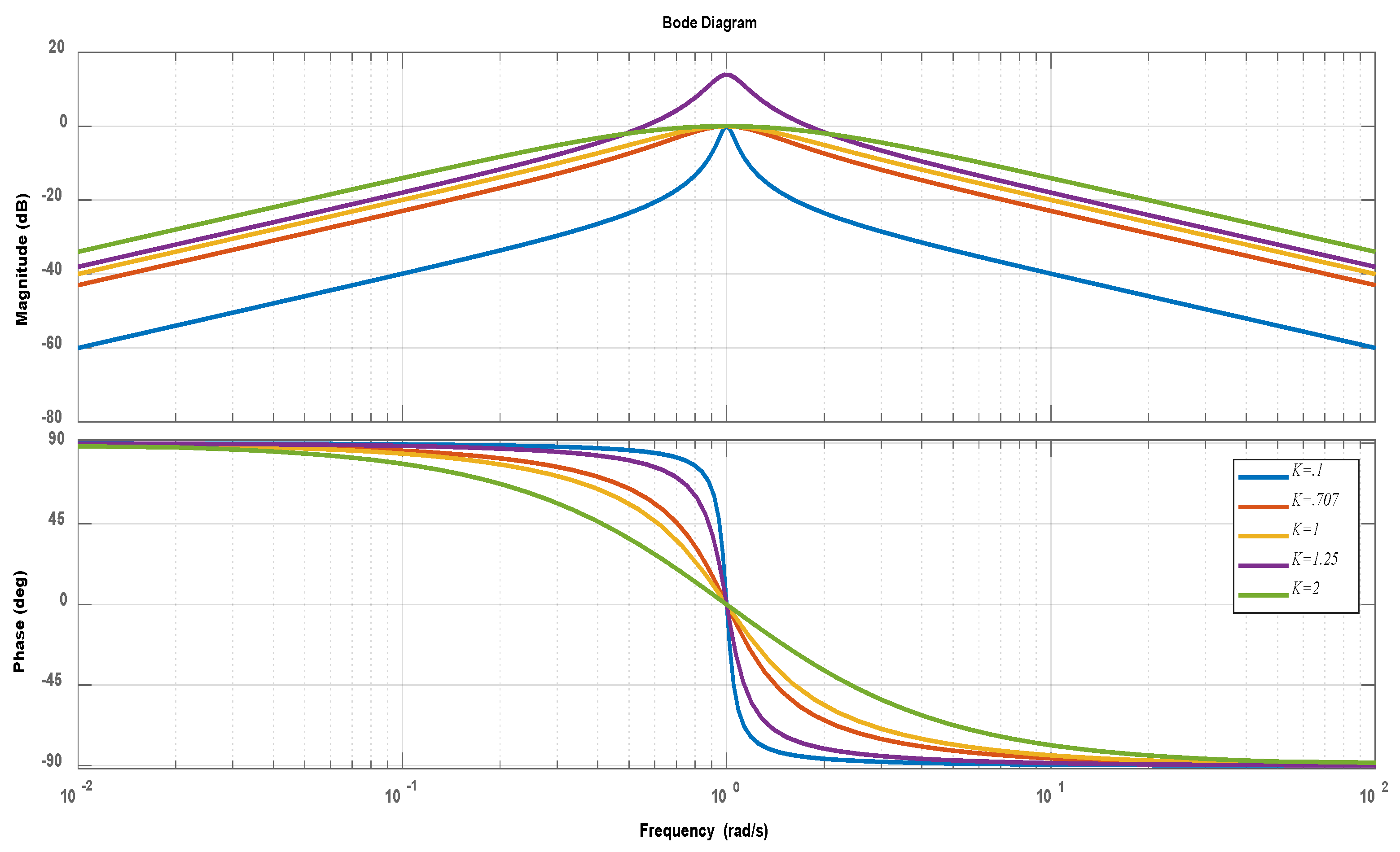
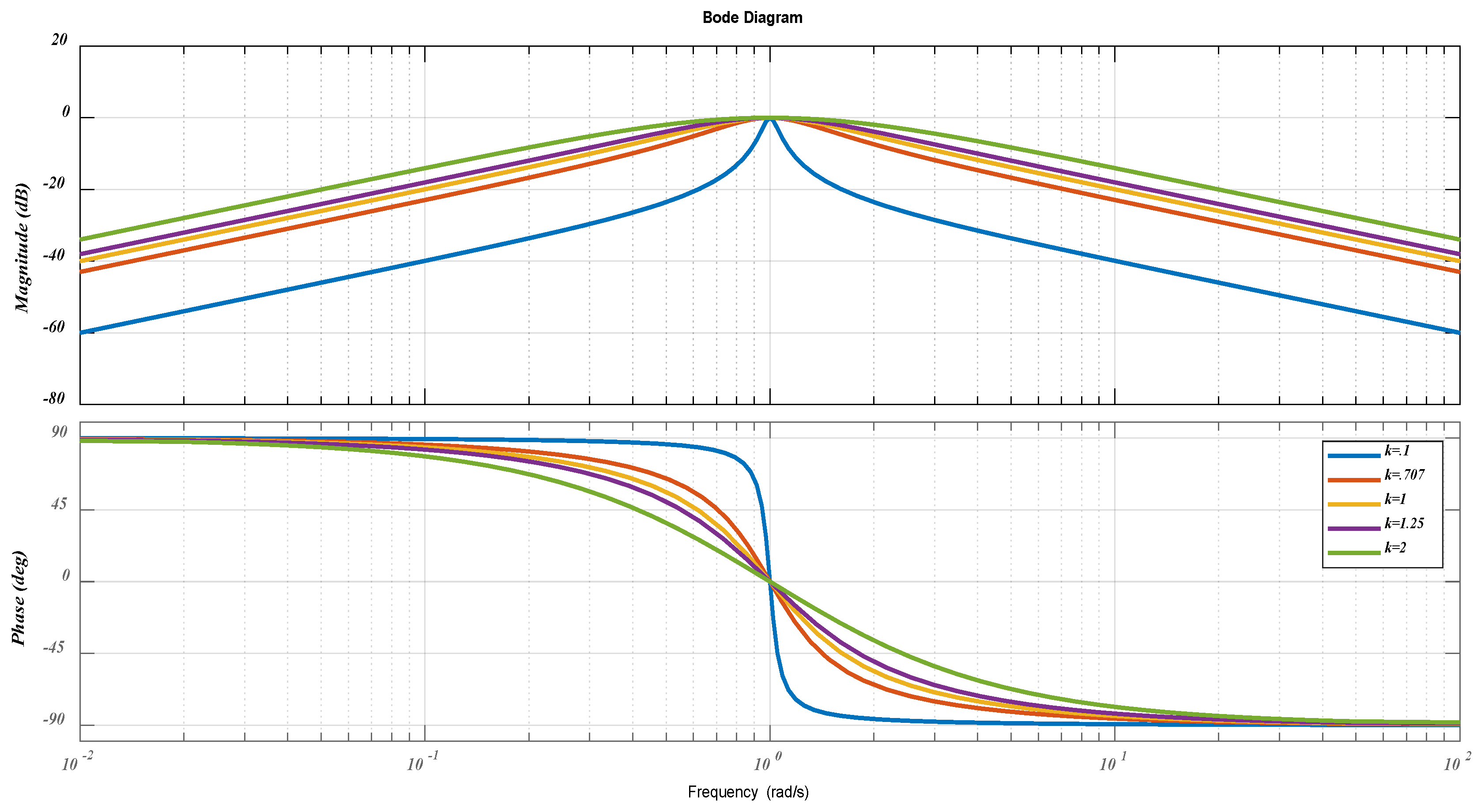
3.2.3. Modeling of Tuning Parameters [35]

The characteristics equation obtained from Equation (47) is
s 2 + ( k ω n 2 ) s + λ 2
The generalized form of the characteristics equation for the second-order system is
s 2 + 2 ϵ ω n s + ω n 2
On comparing Equations (48) and (49), we found 2 ε ω n = k ω n 2 , where ϵ = damping factor, ω n 2 = λ 2 , where ω n = natural frequency and ω n = nominal value of grid frequency.
Consequently, only two parameters, k and λ are to be optimized to the best value so that the optimum tradeoff between settling time and overshoot will occur. From the frequency response of in-phase and quadrature-phase supply voltage, it is quite clear that ϵ = 0.707 (or 1/ 2 ) gives the best tradeoff between settling time and overshoot. So, ϵ = 0.707 (or 1/ 2 ) is considered.
ω n 2 = λ 2 λ = 2 ω n 2 ω n = k ω n 4 ε
λ = k 2 ω n 2 8 ϵ 2
Put ϵ = 1/ 2 :
λ = k 2 ω n 2 4
From (52), it is quite obvious that k and λ are related to each other. In this work, k = 1 / 2 and   λ = 12337 have been selected. Table 1 indicates parameters of SOGI-FLL

4. Non-Linear Loads

4.1. Non-Linear Load of the Voltage Source and Current Source Form

Non-linear loads can be categorized with respect to their harmonic attributes, i.e., voltage-source and current-source type. Figure 13a represents a diode rectifier having a smoothing DC capacitor. Here, the diode rectifiers act as a harmonic voltage source, and the combination of diode rectifiers with the DC capacitor (parallel connected) is known as a voltage source-type non-linear load. Figure 13b represents a diode rectifier with a DC inductor to decrease the DC load current ripple. Here, the diode rectifiers act as a harmonic current source and the combination of diode rectifiers with a DC inductor (series connected) is known as a current source-type non-linear load.

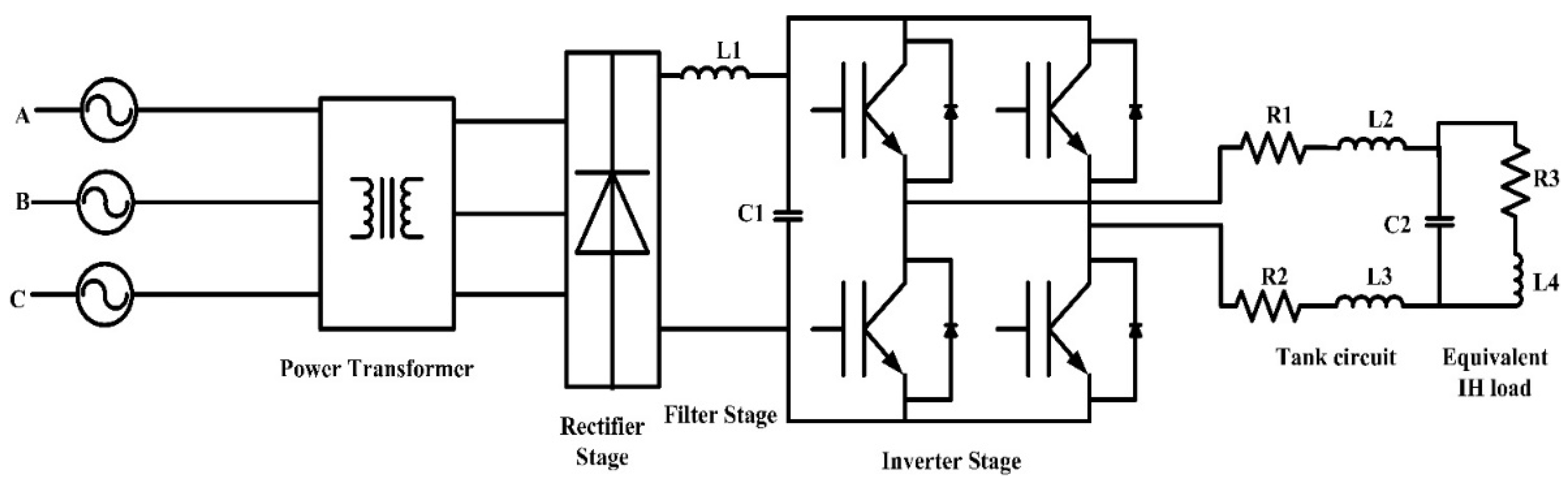
4.2. Induction Heating-Based Non-Linear Load

Figure 14 represents the circuit diagram of an induction heating-based non-linear load. A-B-C represents the three phases of the grid. A power transformer has been employed to step down the voltage of the supply side [36]. The output voltage of the transformer is converted into DC voltage by means of a six-pulse rectifier. This stage is called the rectifier stage. The combination of the inductor and capacitor increases the voltage to the desired level for the inverter. The DC voltage is converted into AC voltage, which increases the frequency in the inverter stage. The inverter output is connected to the induction furnace-based load. In order to provide regulated resonance frequency, the capacitor is shunted with an inductor coil and acts as a tank circuit.

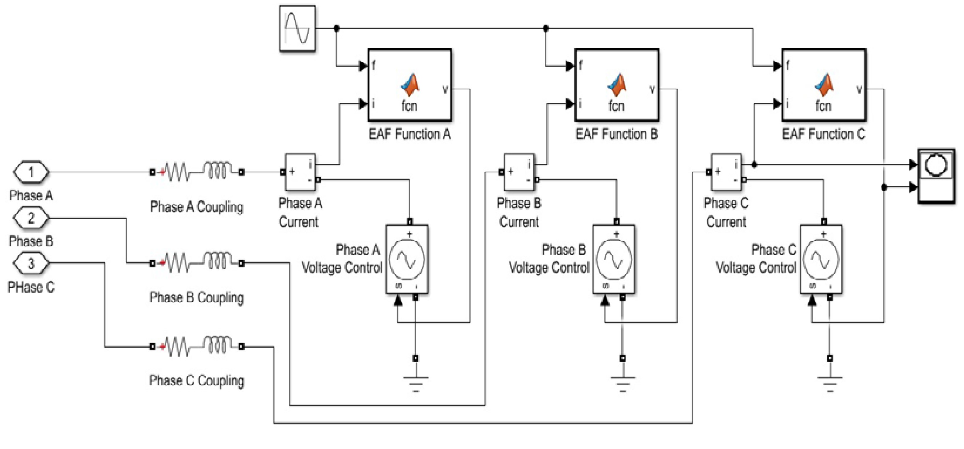
4.3. Electric Arc Furnace Type Non-Linear Load

Figure 15 depicts the circuit diagram of the electric arc furnace (EAF), designed in MATLAB Simulink 2018a. An electric arc furnace has inherent non-linear characteristics due to its time-varying behavior. This property affects the power quality in a distribution line. An EAF is the largest source of flicker voltage and produces odd and even harmonics. Hence, electric arc furnaces are producing voltage quality problems in terms of flicker as well as current quality problems in terms of harmonics.
Detailed analysis of electric arc furnaces is described in [37]:
V h y p ( i ) = { V a t + C ( D + i ) } s g n ( i )
V a t = threshold voltage of arc length, i = phase current, C = arc power, and D = arc current.
V a t ( t ) = V a t 0 [ 1 + m sin ( ω f t ) ]
Flicker voltage is always determined by its threshold voltage.
V a t 0 = base reference voltage when the arc is absent, m = modulation index, and ω f = flicker frequency. Table 2 represents simulation parameters of the proposed work.

5. Analyses of Results

5.1. Performances Investigation under Voltage Source-Based Non-Linear Load

Figure 16 and Figure 17 show the performance of DSTATCOM in uncompensated as well as compensated modes. DC voltage regulation, compensating current, source current, and load current waveforms are represented. During t = [0–0.2] s, DSTATCOM is in the “off” condition and no controller works, hence, no compensation occurs, i.e., no current until 0.2 s. DC voltages have a constant value of 700 V throughout the 0.2 s, and source currents are non-sinusoidal. After 0.2 s, when DSTATCOM is in the “on” condition, source currents become sinusoidal and compensations will start. After some gradual changes in DC voltages, it will stabilize at 0.25 s for Icosθ and at 0.22 s for enhanced SRF SOGI-FLL control, which has been depicted in the figures. Load currents remain non-sinusoidal and the same throughout time due to non-linear load.

5.2. Performances Investigation under Current Source-Based Non-Linear Load

DSTATCOM performances have been validated with current source-type non-linear load under Icosθ and enhanced SRF SOGI-FLL control techniques, which are depicted in Figure 18 and Figure 19. In these figures, various waveforms of DC voltage regulation V d c , compensating current   I c , source current I s , and load current I L have been represented. In the initial stage, when DSTATCOM is “off” at t = [0–0.2] s, source currents I s are distorted, and when DSTATCOM comes into operation, source currents become sinusoidal. DC voltage regulates near 700 V. Due to the transient in the system, the timing for DC voltage regulations differs with respect to controllers. Load currents are non-sinusoidal during the whole period. There are zero and non-zero values of compensating currents in the ‘off’ and ‘on’ states of DSTATCOM, respectively.

5.3. Performances Investigation under Induction Heating-Based Non-Linear Load

Figure 20 and Figure 21 represent the performances of DSTATCOM under different controllers with an induction heating-based non-linear load. As the induction heating is time-varying in nature, it behaves as a non-linear load. During the operation of the induction furnace, the wave shape of the load current is highly deformed because of the large quantity of harmonics established in the system. The DSTATCOM is in the uncompensated mode during [0–0.2] s, and after t = 0.2 s, DSTATCOM comes into operation. So, before 0.2 s, performances of DSTATCOM have not been recognized and they only represent the behavior of non-linear load. In these figures, source currents are non-sinusoidal and its phases are not balanced. Non-sinusoidal source currents create the deterioration of the power factor and reactive power burden. When DSTATCOM comes into operation, source currents become sinusoidal. DC voltages regulate after the quick action of DSTATCOM. Load currents are non-sinusoidal due to the distortion of the sine wave.

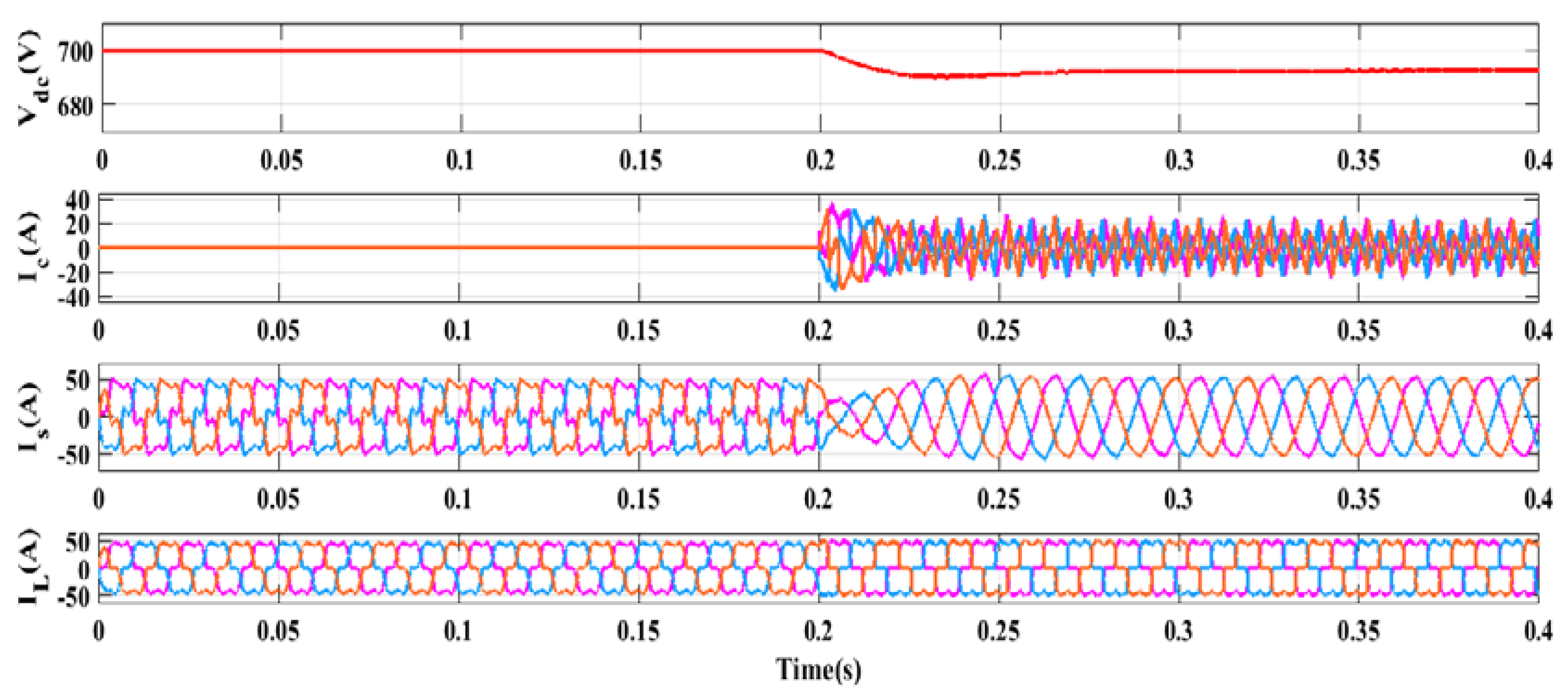
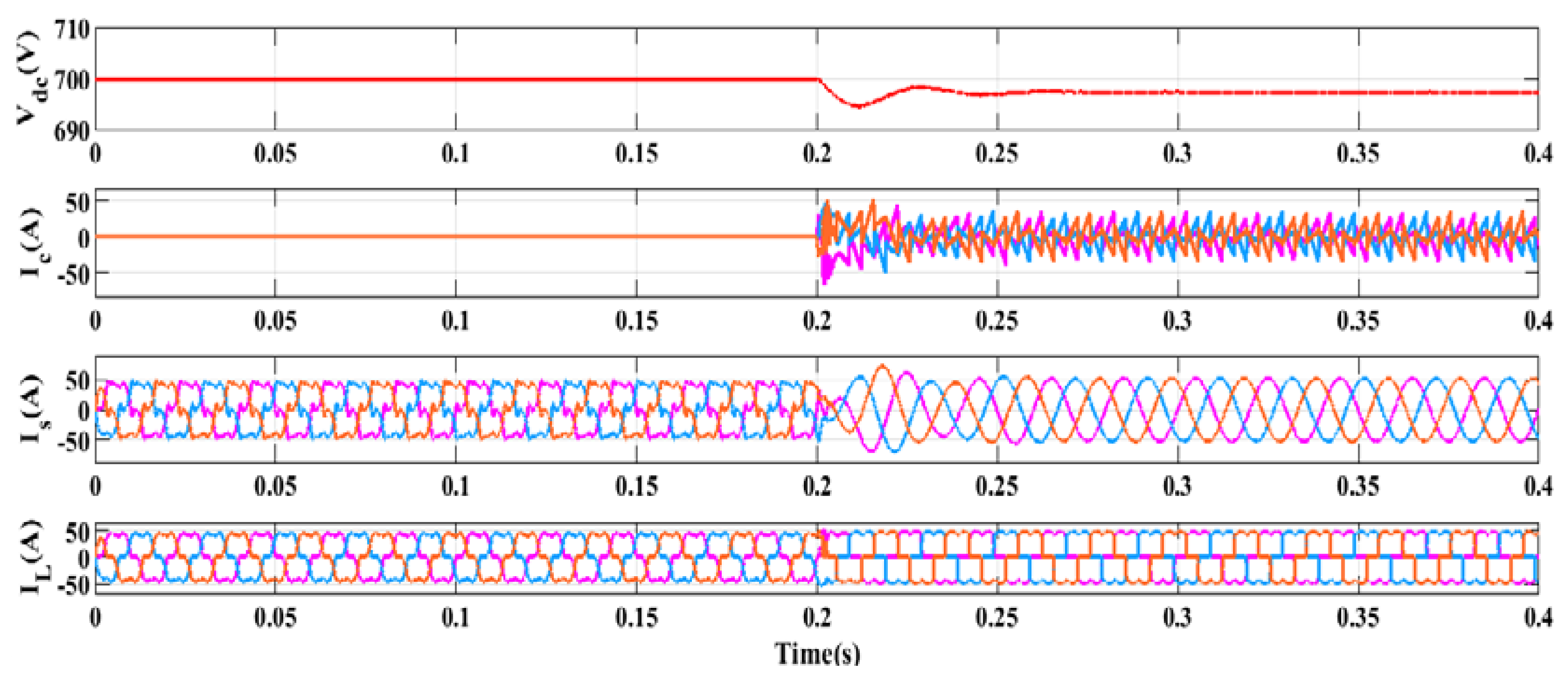
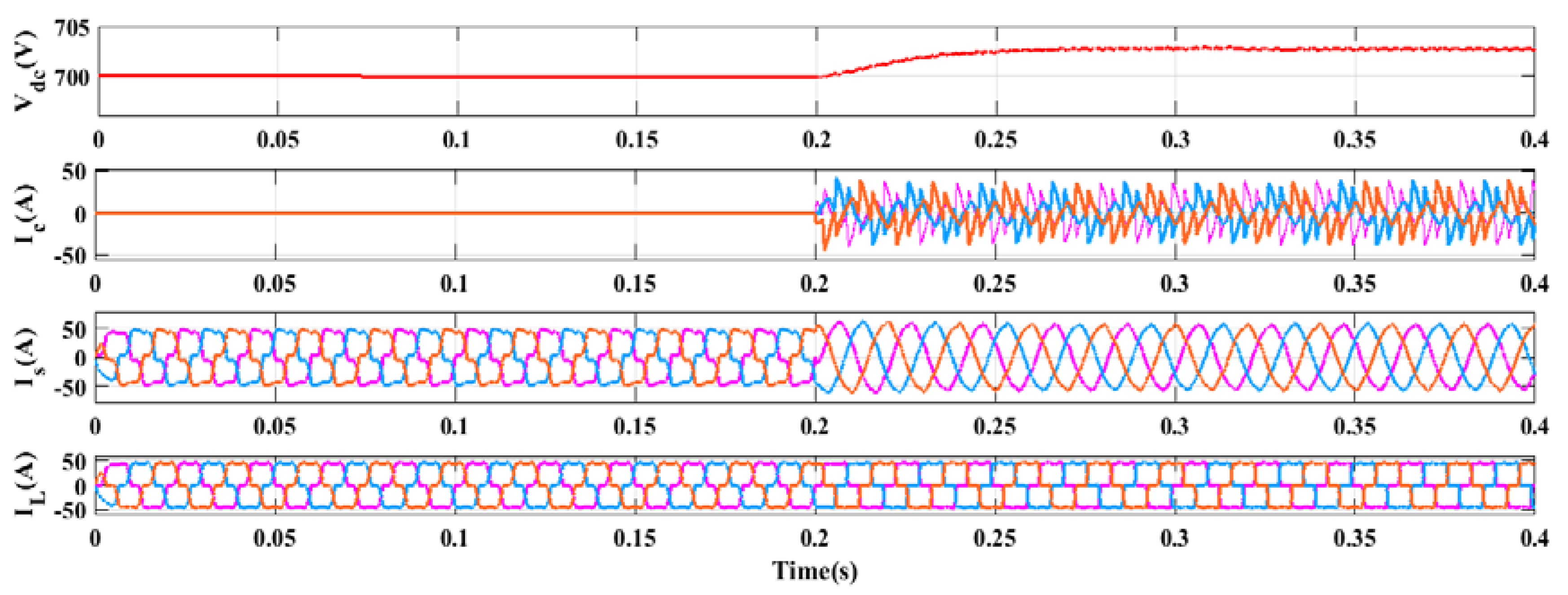
5.4. Performances Investigation under Electric Arc Furnace-Based Non-Linear Load

In the simulation works, the hyperbolic model of an electric arc furnace has been taken as a non-linear load. Figure 22 and Figure 23 represent the performances of DSTATCOM with an electric arc furnace under Icosθ and enhanced SRF SOGI-FLL control techniques. The waveforms of DC voltage regulation, compensating current, source current, and load current have been depicted in these figures. During t = [0–0.2] s, DSTATCOM is in the “off” condition, i.e., no controllers work. Hence, compensator currents show a zero value until 0.2s. DC voltages have the same voltage throughout the 0.2 s, and source currents are non-sinusoidal. After 0.2 s, when DSTATCOM is in the “on” condition, controllers start working, and source currents become sinusoidal. This leads to a reduction of harmonics in the source currents. After some gradual changes in DC voltage regulations, it stabilizes at 0.25 s for Icosθ and 0.21 s for the enhanced SRF SOGI-FLL controller as shown in the figures. The load current waveforms are non-sinusoidal due to non-linear load under the both ‘off’ and ‘On’ condition of the DSTATCOM.
Table 3 represents source current harmonic analysis in terms of % of total harmonic distortion (THD) under various non-linear loads, i.e., voltage Source, current Source, induction furnace, and arc furnace-type non-linear loads having Icosθ and an enhanced SRF SOGI-FLL controller. It has been found that the THDs of source current in Icosθ and the enhanced SRF SOGI-FLL controller are well within the stipulated limits of the IEEE-519 standard [39]. Additionally, the proposed enhanced SRF SOGI-FLL controller-based DSTATCOM has lower THD values (of source current) as compared to the Icosθ controller-based DSTATCOM, which represents better power quality performances of the proposed enhanced SRF SOGI-FLL controller-based DSTATCOM.
Figure 24 shows the comparative analysis of Icosθ and the proposed enhanced SRF SOGI-FLL controller with different non-linear loads. To visualize this figure, DC voltage regulations have been selected as 7 instead of 700 V. It has been also found that the proposed controller gives better features in terms of power factor improvement, THD [40], as well as DC voltage regulation.

6. Conclusions

The deficit consequences of industrial-based non-linear loads on the active behavior of distribution systems are discussed in this article. Traditionally, the Icosθ technique is used to control H-bridge DSTATCOM, but a novel enhanced SRF SOGI-FLL control has also been implemented in the H-bridge DSTATCOM to study the proper behavior of DSTATCOM. This novel control technique is very efficient in grid synchronization and reference current generation for dynamic systems. PWM pulses are generated in a real-time system for voltage source converter switches using a hysteresis control scheme. Both control strategies are capable of controlling the THD value of source currents within the IEEE-519 standard. These control strategies also compensate for reactive power, balance voltage, and current phases, and improve the power factor under a variety of loading conditions. The H-bridge DSTATCOM comparative results demonstrated that the novel enhanced SRF SOGI-FLL control has better power quality improvement features than the Icosθ control under various loading conditions.

Author Contributions

Conceptualization, S.I. and P.K.; methodology, S.I., A.K. and S.R.S.; software, S.I. and S.R.S.; validation, P.K., A.K. and S.R.S.; formal analysis, S.I., P.K., A.K. and S.R.S.; investigation, S.R.S.; resources, S.I. and S.R.S.; data curation, S.I.; writing—original draft preparation, P.K. and S.R.S.; writing—review and editing, S.I., P.K., A.K. and S.R.S.; visualization, S.I. and A.K.; supervision, P.K., A.K. and S.R.S.; project administration, S.I. and A.K.; funding acquisition, P.K. and S.R.S. All authors have read and agreed to the published version of the manuscript.

Funding

Woosong University’s Academic Research Funding-2022.

Data Availability Statement

Not applicable.

Conflicts of Interest

The authors declare no conflict of interest.

References

  1. Ghosh, A.; Ledwich, G. Power Quality Enhancement Using Custom Power Devices; Kluwer: London, UK, 2002. [Google Scholar]
  2. Dugan, R.C.; Mc Granaghan, M.F.; Santoso, S.; Beaty, H.W. Electric Power Systems Quality; McGraw-Hill: New York, NY, USA, 2006. [Google Scholar]
  3. Thentral, T.T.; Palanisamy, R.; Usha, S.; Bajaj, M.; Zawbaa, H.M.; Kamel, S. Analysis of Power Quality issues of different types of household applications. Energy Rep. 2022, 8, 5370–5386. [Google Scholar] [CrossRef]
  4. Fuchs, E.F.; Masoum, M.A.S. Power Quality in Power Systems and Electrical Machines; Elsevier: London, UK, 2008. [Google Scholar]
  5. Myneni, H.; Kumar, G.S. Simple algorithm for current and voltage control of LCL DSTATCOM for power quality improvement. IET Gener. Transm. Distrib. 2019, 13, 423–434. [Google Scholar] [CrossRef]
  6. Chittora, P.; Singh, A.; Singh, M. Simple and efficient control of DSTATCOM in three phase four wire polluted grid system using MCCF-SOGI based controller, IET Gener. Transm. Distrib. 2018, 12, 1213–1222. [Google Scholar] [CrossRef]
  7. Singh, B.; Chandra, A.; Al-Haddad, K. Power Quality: Problems and Mitigation Techniques; John Wiley & Sons: Hoboken, NJ, USA, 2015. [Google Scholar]
  8. Mariscotti, A. Harmonic and Supraharmonic Emissions of Plug-In Electric Vehicle Chargers. Smart Cities 2022, 5, 496–521. [Google Scholar] [CrossRef]
  9. Milešević, B.; Uglešić, I.; Filipović-Grčić, B. Power quality analysis in electric traction system with three-phase induction motors. Electr. Power Syst. Res. 2016, 138, 172–179. [Google Scholar] [CrossRef]
  10. Singh, B.; Bhuvaneswari, G.; Garg, V. 24-Pulse AC-DC Converter for Power Quality Improvement in Vector Controlled Induction Motor Drives. Electr. Power Compon. Syst. 2006, 34, 1077–1098. [Google Scholar] [CrossRef]
  11. Cespedes, M.; Sun, J. Impedance modelling and analysis of grid-connected voltage-source converters. IEEE Trans. Power Electron. 2014, 29, 1254–1261. [Google Scholar] [CrossRef]
  12. Malathi, S.; Jayachandran, J. FPGA implementation of NN based LMS–LMF control algorithm in DSTATCOM for power quality improvement. Control. Eng. Pract. 2020, 98, 104378. [Google Scholar] [CrossRef]
  13. Qasim, M.; Kanjiya, P.; Khadkikar, V. Optimal current harmonic extractor based on unified ADALINEs for shunt active power filters. IEEE Trans. Power Electron. 2014, 29, 6383–6393. [Google Scholar] [CrossRef]
  14. Latran, M.B.; Teke, A.; Yoldaş, Y. Mitigation of power quality problems using distribution static synchronous compensator: A comprehensive review. IET Power Electron. 2015, 8, 1312–1328. [Google Scholar] [CrossRef]
  15. Bouafia, S.; Benaissa, A.; Barkat, S.; Bouzidi, M. Second order sliding mode control of three level four leg DSTATCOM based on instantaneous symmetrical component theory. Energy Syst. 2018, 9, 79–111. [Google Scholar] [CrossRef]
  16. Mangaraj, M.; Panda, A.K. Performance analysis of DSTATCOM employing various control algorithms. IET Gener. Transm. Distrib. 2017, 11, 2643–2653. [Google Scholar] [CrossRef]
  17. Kumar, P.; Kumar, N.; Akella, A.K. A Simulation Based Case Study for Control of DSTATCOM. ISA Trans. 2014, 53, 767–775. [Google Scholar] [CrossRef] [PubMed]
  18. Nunes, W.T.; Encarnação, L.F.; Aredes, M. An Improved Asymmetric Cascaded Multilevel D–STATCOM with Enhanced Hybrid Modulation. Electronics 2015, 4, 311–328. [Google Scholar] [CrossRef] [Green Version]
  19. Shahgholian, G.; Azimi, Z. Analysis and Design of a DSTATCOM Based on Sliding Mode Control Strategy for Improvement of Voltage Sag in Distribution Systems. Electronics 2016, 5, 41. [Google Scholar] [CrossRef] [Green Version]
  20. Irfan, M.M.; Rangarajan, S.S.; Collins, E.R.; Senjyu, T. Enhancing the Power Quality of the Grid Interactive Solar Photovoltaic-Electric Vehicle System. World Electr. Veh. J. 2021, 12, 98. [Google Scholar] [CrossRef]
  21. Satish, R.; Vaisakh, K.; Abdelaziz, A.Y.; El-Shahat, A. A Novel Three-Phase Harmonic Power Flow Algorithm for Unbalanced Radial Distribution Networks with the Presence of D-STATCOM Devices. Electronics 2021, 10, 2663. [Google Scholar] [CrossRef]
  22. Alshareef, S.M. Analyzing and Mitigating the Impacts of Integrating Fast-Charging Stations on the Power Quality in Electric Power Distribution Systems. Sustainability 2022, 14, 5595. [Google Scholar] [CrossRef]
  23. Mora-Burbano, J.A.; Fonseca-Díaz, C.D.; Montoya, O.D. Application of the SSA for Optimal Reactive Power Compensation in Radial and Meshed Distribution Using D-STATCOMs. Algorithms 2022, 15, 345. [Google Scholar] [CrossRef]
  24. Irfan, M.M.; Malaji, S.; Patsa, C.; Rangarajan, S.S.; Hussain, S.M.S. Control of DSTATCOM Using ANN-BP Algorithm for the Grid Connected Wind Energy System. Energies 2022, 15, 6988. [Google Scholar] [CrossRef]
  25. Chen, J.-H.; Tan, K.-H.; Lee, Y.-D. Intelligent Controlled DSTATCOM for Power Quality Enhancement. Energies 2022, 15, 4017. [Google Scholar] [CrossRef]
  26. Dash, A.; Bagarty, D.P.; Hota, P.K.; Sahu, M.K.; Hazra, T.; Behera, S.; Behera, A.K.; Behera, S.; Nayak, A.K.; Mohapatra, S.B.; et al. Grid-Tied Distribution Static Synchronous Compensator for Power Quality Enhancement Using Combined-Step-Size Real-Coefficient Improved Proportionate Affine Projection Sign Algorithm. Energies 2022, 15, 197. [Google Scholar] [CrossRef]
  27. Golestan, S.; Guerrero, J.M.; Vasquez, J.C.; Abusorrah, A.M.; Al-Turki, Y. Modeling, tuning, and performance comparison of advanced second-order generalized integrator-based FLLs. IEEE Trans. Power Electron. 2018, 33, 10229–10239. [Google Scholar] [CrossRef] [Green Version]
  28. Duarte, S.N.; Souza, B.C.; Almeida, P.M.; Araujo, L.R.; Barbosa, P.G. Control algorithm for DSTATCOM to compensate consumer generated negative and zero sequence voltage unbalance. Int. J. Electr. Power Energy Syst. 2019, 120, 105957. [Google Scholar] [CrossRef]
  29. Penthia, T.; Panda, A.K.; Mangaraj, M. Experimental Validation of ADALINE Least Mean Square Algorithm in a Three-Phase Four-Wire DSTATCOM to Enhance Power Quality. Electr. Power Compon. Syst. 2020, 48, 769–780. [Google Scholar] [CrossRef]
  30. Jampana, B.; Veramalla, R.; Askani, J. Performance of four-leg VSC based DSTATCOM using single phase PQ theory. J. Inst. Eng. India Ser. B 2017, 98, 65–76. [Google Scholar] [CrossRef]
  31. Raveendra, N.; Madhusudhan, V.; Jaya Laxmi, A. RFLSA control scheme for power quality disturbances mitigation in DSTATCOM with n-level inverter connected power systems. Energy Syst. 2020, 11, 753–788. [Google Scholar] [CrossRef]
  32. Singh, B.; Kandpal, M.; Hussain, I. Control of grid tied smart PV-DSTATCOM system using an adaptive technique. IEEE Trans. Smart Grid 2018, 9, 3986–3993. [Google Scholar] [CrossRef]
  33. Puranik, V.; Arya, S.R. SOGI-FLL based adaptive filter for DSTATCOM under variable supply frequency. J. Inst. Eng. India Ser. B 2017, 98, 423–431. [Google Scholar] [CrossRef]
  34. Punna, S.; Mailugundla, R.; Salkuti, S.R. Design, Analysis and Implementation of Bidirectional DC–DC Converters for HESS in DC Microgrid Applications. Smart Cities 2022, 5, 433–454. [Google Scholar] [CrossRef]
  35. Zou, Z.X.; Liserre, M. Modeling phase-locked loop-based synchronization in grid-interfaced converter. IEEE Trans. Energy Convers. 2019, 35, 394–404. [Google Scholar] [CrossRef]
  36. Saggu, T.S.; Singh, L.; Gill, B. Harmonics Mitigation in a Steel Industry using eleven level Cascaded Multilevel Inverter based Dstatcom. Can. J. Electr. Comput. Eng. 2017, 40, 110–115. [Google Scholar] [CrossRef]
  37. Bhonsle, D.C.; Kelkar, R.B. Analyzing power quality issue in electric arc furnace by modeling. Energy 2016, 115, 830–839. [Google Scholar] [CrossRef]
  38. Noroozi, M.; Haghjoo, F.; Javadi, H.; Zolghadri, M.R. Power quality improvement in single-phase transformerless semi-quasi-Z-source inverters for off-grid photovoltaic systems. Int. J. Electr. Power Energy Syst. 2023, 145, 108703. [Google Scholar] [CrossRef]
  39. IEEE. Recommended Practice and Requirements for Harmonic Control in Electric Power Systems—Redline. In IEEE Std 519-2014 (Revision of IEEE Std 519-1992)—Redline; IEEE: Piscataway, NJ, USA, 2014; pp. 1–213. [Google Scholar]
  40. Hemalatha, R.; Ramasamy, M. Microprocessor and PI controller based three phase CHBMLI based DSTATCOM for THD mitigation using hybrid control technique. Microprocess. Microsystem. 2020, 76, 103093. [Google Scholar] [CrossRef]
Figure 1. Configuration of H-bridge-based DSTATCOM system (* indicates reference value).
Smartcities 05 00081 g001
Figure 2. In-phase and Q-phase of the unit vector.
Smartcities 05 00081 g002
Figure 3. Design of I_cp.
Smartcities 05 00081 g003
Figure 4. Design of I_cq.
Smartcities 05 00081 g004
Figure 5. Design of I L p a and I L q a .
Smartcities 05 00081 g005
Figure 6. Design of amplitude of d-axis load current.
Smartcities 05 00081 g006
Figure 7. Design of amplitude of q-axis load current.
Smartcities 05 00081 g007
Figure 8. Gate pulse generation (* indicates reference value)
Smartcities 05 00081 g008
Figure 9. Block diagram of enhanced SRF SOGI-FLL controller [34].
Smartcities 05 00081 g009
Figure 10. Block diagram of standard SOGI-FLL.
Smartcities 05 00081 g010
Figure 11. Frequency response plot of v α ( s )
Smartcities 05 00081 g011
Figure 12. Frequency response plot of v β ( s )
Smartcities 05 00081 g012
Figure 13. Circuit diagrams of three phase non-linear loads.
Smartcities 05 00081 g013
Figure 14. Circuit diagram of induction heating-based load.
Smartcities 05 00081 g014
Figure 15. Circuit configuration of electric arc furnace.
Smartcities 05 00081 g015
Figure 16. Performance of Icosθ control-based DSTATCOM under voltage-source non-linear load.
Smartcities 05 00081 g016
Figure 17. Performance of enhanced SRF SOGI-FLL control DSTATCOM under voltage-source non-linear load.
Smartcities 05 00081 g017
Figure 18. The behavior of Icosθ-based DSTATCOM in current source-based non-linear load.
Smartcities 05 00081 g018
Figure 19. The behavior of enhanced SRF SOGI-FLL-based DSTATCOM under current source-based non-linear load.
Smartcities 05 00081 g019
Figure 20. The behavior of Icosθ-based DSTATCOM with induction heating-based non-linear load.
Smartcities 05 00081 g020
Figure 21. The behavior of enhanced SRF SOGI-FLL-based DSTATCOM with induction heating-based non-linear load.
Smartcities 05 00081 g021
Figure 22. Performance of Icosθ-based DSTATCOM with electric arc furnace-based non-linear load.
Smartcities 05 00081 g022
Figure 23. Performance of enhanced SRF SOGI-FLL-based DSTATCOM with electric arc furnace-based non-linear load.
Smartcities 05 00081 g023
Figure 24. Bar representation of comparative analysis.
Smartcities 05 00081 g024
Table 1. SOGI Parameters.
ParametersValue
SOGI gain 1 / 2
FLL gain 12337
Frequency50 Hz
Nominal angular frequency ω n 2 π × 50   rad/s
Table 2. Simulation parameters with the application of various loads [38].
Non-Linear LoadsParameter Used in the SimulationApplicationPower Quality Issues
Voltage source-based R 1 = 12   , C 1 = 5 μFHousehold appliances, switched-mode power supply (SMPS)Harmonics, power factor deterioration, reactive power burden
Current source-based L 1 = 0.002 H,
R 1 = 12  
Electric motor, industrial loadCurrent harmonics, power factor deterioration, reactive power burden
Induction heating-based R 1 = 5  
R 2 = 12  
R 3 = 20  
L 1 = 0.002 H
L 2 = 0.006 H
L 3 = 0.008 H
L 4 = 0.003 H
C 1 = 5 μF
C 2 = 2.5 μF
Steel industries, cooking induction heaterUnbalanced phases, reactive power burden, harmonics
Electric Arc Furnace V a t ( t ) = 360 V
m = 0.2
ω f = 0.4
V a t 0 = 200 V
C = 23,000
D = 5000
Welding industries, heavy engineering industriesFlicker, voltage fluctuation, harmonics
DSTATCOM V d c = 700   V
L 1 = 0.0004 H
C d c = 9000 μF
Power quality issues’ mitigation
Source/Grid V = 415 V
R s = 0.001  
L s = 0.002 H
Table 3. Comparative source current harmonic analysis in %THD.
Non-Linear LoadHarmonic Order
(Uncompensated Mode)
Control AlgorithmHarmonic Order
(Compensated Mode)
3rd5th7th9th3rd5th7th9th
Voltage source4.12%6.23%2.23%1.5%Icosθ2.32%1.18%0.98%0.63%
SOGI-FLL2.10%1.02%0.78%0.63%
Current source3.25%5.32%2.01%1.9%Icosθ2.01%1.23%0.69%0.25%
SOGI-FLL1.98%1.25%0.32%0.21%
Induction furnace5.72%3.12%2.03%1.02%Icosθ2.15%0.96%1.78%0.89%
SOGI-FLL2.89%1.06%1.54%0.26%
Arc furnace6.89%4.07%2.30%1.87%Icosθ2.96%1.23%0.75%0.23%
SOGI-FLL1.56%1.25%0.89%0.45%
Publisher’s Note: MDPI stays neutral with regard to jurisdictional claims in published maps and institutional affiliations.

