Article

Multi-Analytical Study of Damage to Marine Ballast Tank Coatings After Cyclic Corrosion Testing

by
Yanwen Liu
1,
Douglas Beaumont
2,
Xiaorong Zhou
1,
Timothy Burnett
1,
Suzanne Morsch
1,
Stuart Lyon
1,*,
Paul Iannarelli
2,
Claudio Di Lullo
2,
Niek Hijnen
2,
Reza Emad
1,
Lawrence Coghlan
1 and
Teruo Hashimoto
1
1
Corrosion@Manchester, Department of Materials, The University of Manchester, Manchester M13 9PL, UK
2
AkzoNobel, Stoneygate Lane, Felling, Gateshead NE10 0JY, UK
*
Author to whom correspondence should be addressed.
Corros. Mater. Degrad. 2025, 6(1), 1; https://doi.org/10.3390/cmd6010001
Submission received: 8 November 2024 / Revised: 29 November 2024 / Accepted: 19 December 2024 / Published: 24 December 2024
(This article belongs to the Special Issue Advances in Corrosion Protection by Coatings)

Abstract

:
Seawater ballast tanks in vessels are subject to severe service conditions caused by repeated filling/emptying, as well as temperature variation. Consequently, relatively thick, barrier-type coatings are used for corrosion protection of their internals. These are generally formulated with solvent-based epoxy binders and contain a range of flake pigments designed to limit environmental entry. Here, we report on a detailed study of damage processes in order to understand the mechanisms of failure after hygro-thermal cyclic corrosion testing. Similar formulations were cured using variant phenalkamine cross-linkers. Visual observation after corrosion testing shows minimal changes and no sign of corrosion damage. However, high-resolution analytical microscopy and nanoscale tomography reveal the onset of microstructural and chemical damage processes inside the coating. Thus, kaolin and talc pigments in the coating remained stable under hygro-thermal cycling; however, dolomite and barium sulphate dissolved slightly, causing voids. Galvanic protection of the substrate by aluminium flake pigments was disproven as no electrical connection was evident. Vibrational spectroscopy revealed a decrease in residual epoxy functionality after exposure for the coating cured with the more stable phenalkamine. This was correlated with an increase in glass transition temperature (Tg) and no observable corrosion of aluminium flakes. In contrast, the less stable phenalkamine cross-linker caused the binder Tg to decrease and aluminium flakes and substrate corrosion to become evident.

1. Introduction

Protective coatings used in the water ballast tanks of ships and offshore structures are commonly based on epoxy-amine polymer binders pigmented with mineral extender pigments [1,2], including talc, kaolin, micas etc. [2,3]. Additionally, aluminium flake pigments can be included to restrict under-coating corrosion and give improved resistance to cathodic delamination at coating defect areas [1]. Properly formulated and applied, these barrier coatings typically last in excess of 20 years while operating under the aggressive conditions present in ship ballast tanks, which typically involve hygro-thermal cycling between elevated temperatures at high humidity and ambient temperatures immersed in sea water [4,5,6,7]. Although current high-performance barrier coatings used in marine environments meet industry requirements, increasing regulatory pressure will require manufacturers to develop newer coatings which meet the evolving environmental protection requirements (i.e., lower volatile organic compounds (VOCs) and fewer substances of very high concern (SVHC)) and compliance with environmental regulations (i.e., REACH: Registration, Evaluation, Authorization of Chemicals in the EU) [8]. Since the service life of these protective coatings is in the order of decades, it is a major challenge to create and interpret accelerated laboratory tests to manage a developmental cycle which is much shorter than their service life. To confidently speed up the development of coatings that meet evolving environmental regulation whilst retaining their durability in service, it is necessary to understand the coating degradation mechanisms, which are influenced by the formulation, i.e., polymer binders and pigments/extender pigments and processing.
Originally tar epoxy resins (containing epoxy resin and coal tar) were used for water ballast tank coatings and showed excellent stability with minimal degradation over long service lives [9]. However, these materials have long been phased out due to their toxicity and substituted by pure, or hydrocarbon-modified, epoxy-amines/amides. Numerous studies have found that prolonged hygro-thermal ageing may lead to irreversible damage of these resins due to susceptibility of the polymer binder to oxidation [10,11,12,13], or hydrolysis [14]. Degradation is commonly accompanied by a change in the glass transition temperature (Tg), where increases in Tg represent an increase in the rigidity of the coating and decreasing (Tg) signifies softening. Increases in the Tg was proposed to be due to a combination of continued loss of solvent, polymer relaxation processes, and further cross-linking [12,15,16,17]. On the other hand, a decrease in Tg has been attributed to oxidation or hydrolysis-associated chain scission [14,18].
The presence of flaky/lamellar aluminium pigments is found to improve corrosion resistance and reduce the extent of delamination of coatings from steel panels [1,19,20,21,22,23]. However, a known drawback of flaky pigments is that solvent evaporation is retarded [3]. High-aspect ratio pigments such as aluminium flakes reduce environmental transport and provide reinforcement resisting volume changes due to environmental changes, consequentially reducing the internal strain/stress of the binder [24]. Extender oxide pigments such as talc, mica, and kaolin, enhance barrier protection [25], increase mechanical properties (elastic modulus and hardness) [26], and increase water resistance [27]. Talc has been found to be more effective than mica or carbonate minerals (e.g., dolomite) in providing corrosion protection to steel substrates [28]. Kaolin is an environmentally friendly material which improves opacity and gloss and extends service life [29,30], and micaeous iron oxide also improves the corrosion protection properties of coatings [31].
Many previous studies on such types of coating are based on electrochemical, gravimetric, and related measurements but not direct microstructural observation, for which there are very few reports in the literature. In this paper, we use analytical microscopy, supported by vibrational and thermal spectroscopy, to identify damage processes in barrier-type coatings under cyclic hygro-thermal testing conditions before they become apparent visually.

2. Experimental Methods

An organic coating, intended for use as corrosion protection for seawater ballast tanks in vessels, was formulated and applied to steel panels (details below). After application and curing, some panels were retained as unexposed controls while the remainder were subject to 6 months of cyclic hygro-thermal ageing (details below). Barrier-type coatings are generally used for this very demanding application and generally comprise an epoxy-amine binder pigmented with low-dimensional flake-like pigments, for example, aluminium, kaolin (layered aluminium silicate), mica (layered magnesium/aluminium silicate), and talc (magnesium silicate).
The reference coatings were applied onto 10 cm by 15 cm low carbon steel substrates (similar to AISI 1050) of 4 mm thickness, which were grit-blasted to SA 2.5 (ISO 8501-1) and allowed to cure at ambient laboratory temperature (18–22 °C) under dust-free conditions. The dry film thickness (±10%) was about 350 microns, comprising two coats each of about 175 microns. Coatings were formulated at 70 ± 2% NH stoichiometry on epoxy groups with nominally identical pigment materials (albeit from different suppliers), pigment volume concentration (~28 ± 2%), and solvent content and applied by airless spray or draw-down applicator bar, as indicated in Table 1. The intent was to identify performance differences arising from the application method (draw-down bar v. airless spray) and two variant cross-linking agents (phenalkamine #1 and #2).
To simulate conditions occurring between alternately full and drained ballast tanks of crude oil or chemical products tankers carrying hot cargoes, the coated panels were exposed to a hygro-thermal cyclic corrosion test (CCT) with repeated weekly cycles of 4 days of immersion at 25 °C in artificial seawater (ASTM 1141) and then 3 days at 70 °C and 100% relative humidity. The test duration was 26 weeks with examination carried out before exposure and on samples from the same batch after exposure. Control (i.e., unexposed) samples were analysed together with exposed samples after the cyclic corrosion testing was completed.
The coating microstructure was characterised using analytical scanning electron microscopy (SEM: Zeiss Germany, models “Sigma” and “Merlin”). Elemental mapping and analysis were performed using energy dispersive x-ray analysis and/or back-scattered electron imaging. X-ray nano-computerised tomography (CT) used a Zeiss Xradia 810 Ultra X-ray microscope in absorption contrast mode. Samples were sectioned for X-ray nano-CT using a Thermo-Scientific Helios 5 Laser Focused Ion Beam (FIB). Three-dimensional images were reconstructed from ~350 × 2D slices, resulting in an analytical volume of ~30 × 30 × 40 microns, giving a voxel resolution of ~150 nm3. Grey-scale segmentation and conversion of the nano-CT raw data into false-colour images were undertaken using Avizo 3D software, v.2022.2 (Thermo-Scientific, UK).
Chemical changes to the coatings were studied using Fourier transform infrared spectroscopy (FTIR: Nicolet iS10 Spectrometer). Spectra were averaged over at least 32 measurements with 4 cm−1 resolution across the 500 to 4000 cm−1 range. Measurements were obtained from the coating surface in attenuated total reflection (ATR) geometry using the Nicolet Smart iTX sampling accessory with a ZnSe crystal.
Samples of the coating were detached from substrates mechanically and cut into representative sections weighing between 1 and 2 g. Glass transition temperatures (Tg) were then determined using differential scanning calorimetry (DSC, Netzsch 200 F3) before and after cyclic corrosion testing using Netzsch Proteus software, v.7. Between 5 and 10 samples were used for each Tg determination using a heating rate of 10 °C per minute. The variation in measured Tg for nominally identical samples was less than 1.5 °C.

3. Results

3.1. Visual Appearance

Optical images of the coating surfaces before and after exposure were obtained using a digital camera. The images are relatively featureless before testing (Figure 1a,c,e). Significantly, they show minimal changes after corrosion testing and certainly no signs of corrosion damage (Figure 1b,d,f), although samples prepared with the phenalkamine #2 cross-linker showed colour changes. The absence of visual damage is important to show here because internal microstructural changes, including substrate corrosion, are revealed using high-resolution cross-sectional microscopy in later figures.

3.2. Thermal Analysis

The glass transition temperatures (Tg) of the coatings were measured using DSC [32]. For cross-linked thermosets, such as epoxy binders in protective coatings, the glass transition temperature (Tg) is the point at which a rigid (glassy) structure becomes more flexible. This, in turn, reflects the degree of polymer chain cross-linking and mobility. Environmental exposure may cause additional cross-linking (higher Tg) or chain breaking (lower Tg), while water ingress will cause plasticisation (lower Tg). Vibrational (infrared) spectroscopy provides qualitative and quantitative data on the functional groups present in the polymer. Environmental exposure will cause water ingress (i.e., increase in -OH absorption) and may cause hydrolysis of susceptible bonds (e.g., decrease in ester absorption).
Values of Tg are listed in Table 2. The variability of repeated measurements was less than 1.5 °C, and therefore, the changes reported are statistically significant. Tg decreased for coatings B and C, indicating plasticisation of the polymer binder by water ingress and/or chain bond breaking. In contrast, the Tg of coating A increased, which indicates increased cross-linking and greater bond stability.

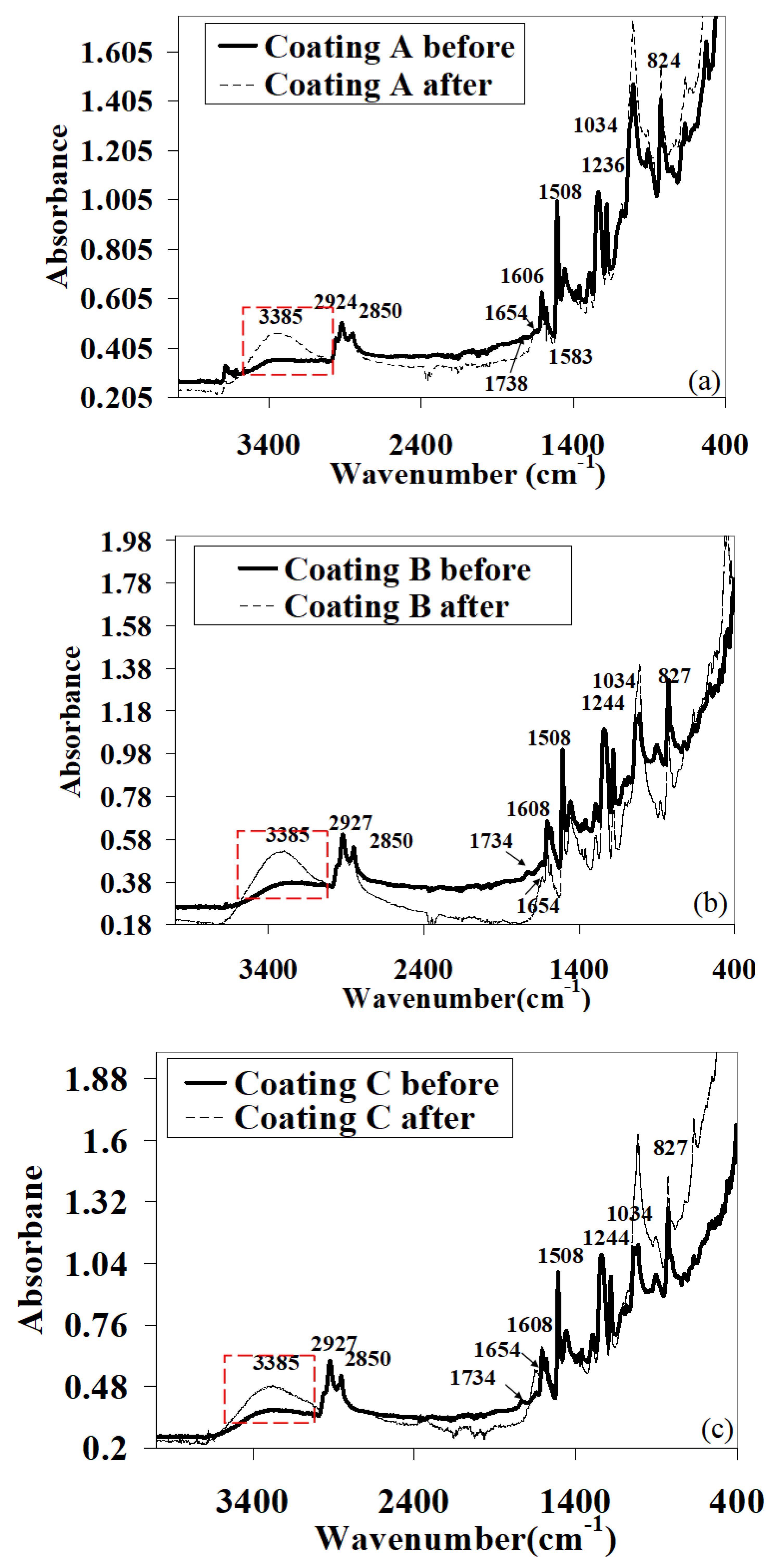
3.3. Vibrational Spectroscopy

Attenuated total reflection FTIR spectra obtained from unexposed coating surfaces were normalised to the aromatic absorbance band at 1508 cm−1 (Figure 2). Characteristic features of epoxy binders were observed in all spectra, including p-phenylene groups (824 cm−1), an epoxy functional group (912 cm−1), ether C–O stretch (1034 cm−1), phenyl C–O stretch (1236 cm−1), (CH3)2 gem dimethyl C–H deformation (1362 and 1382 cm−1), aromatic doublet peaks (1454, 1508, 1583, and 1606 cm−1), an amide C=O carbonyl group at (1654 cm−1), aliphatic C–H stretching (2850 and 2924 cm−1), and a broad peak associated with hydrogen-bonded O–H stretching centred on 3380 cm−1 [33,34,35,36]. The only significant difference observed between the coatings was an ester link (-(C=O)-O) at 1734 cm−1, which was present in coatings B and C (phenalkamine #2) but absent in coating A (phenalkamine #1). After exposure, a significant increase in absorbance in the O-H stretching around 3380 cm−1 was evident in all coatings and associated with water uptake and metal oxidation.
Figure 3 shows zoomed spectra for coatings A (phenalkamine #1) and C (phenalkamine #2) for the bands 760 to 960 cm−1 (epoxy) and 1400 to 1800 cm−1 (carbonyl). Since the same cross-linker was used for coating B, the results are not reported. Epoxy absorption in coating A at 912 cm−1 decreased after exposure, which implies increased cross-linking of the polymer binder. This is consistent with the measured increase in Tg. Conversely, no significant reduction in the epoxy peak was observed for coating C. Instead, a significant increase in amide C=O carbonyl at 1654 cm−1 was accompanied by the disappearance of –(C=O)–O ester at 1734 cm−1. This is indicative of bond hydrolysis, chain scission, and decreasing cross-linking, explaining the reduced Tg observed for coatings B and C.

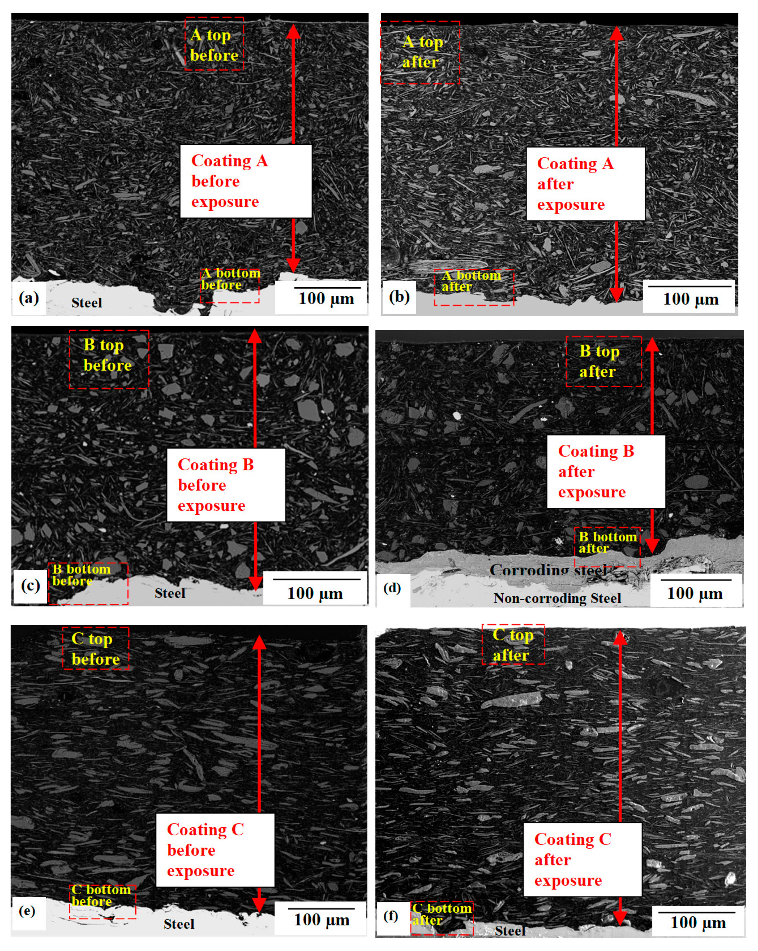
3.4. Coating Cross-Section

Coatings were examined in cross-section before and after exposure using back-scattered scanning electron microscopy (BSE-SEM) (Figure 4). In this mode, image contrast is representative of local net atomic number. Thus, lighter regions have higher atomic numbers (more scattering) and darker regions have lower atomic numbers (less scattering). Pigments are therefore revealed as regions with lighter contrast, whereas the polymer binder appears darker. The substrate is visible at the bottom of each image as a bright region. Pigment volume concentrations (PVCs), quantified from the 2D sections, were respectively 30%, 29.5%, and 26.3% for coatings A, B, and C, which is consistent with the designed formulation (PVC of 28 ± 2%.) Substrate corrosion is evident in coatings B and C (phenalkamine #2) as the grey region visible adjacent to the steel, which corresponds to an iron oxide corrosion product. On the other hand, corrosion was not observed in coating A (phenalkamine #1). Draw-bar application (coating C) appears to cause flake pigments to align slightly more parallel with the substrate compared with spray application (coating B). However, the differences are minor, and it appears that draw-bar application produces similar microstructural morphology to spray application, at least in this experiment.

3.5. High-Resolution Analytical Microscopy

The dotted areas indicated in Figure 4 comprise representative regions selected from the top and the bottom of the coating. These were zoomed and imaged at high resolution, with analysis using energy dispersive x-ray spectroscopy (EDX), and are presented in Figure 5 (coating A), Figure 6 (coating B), and Figure 7 (coating C).

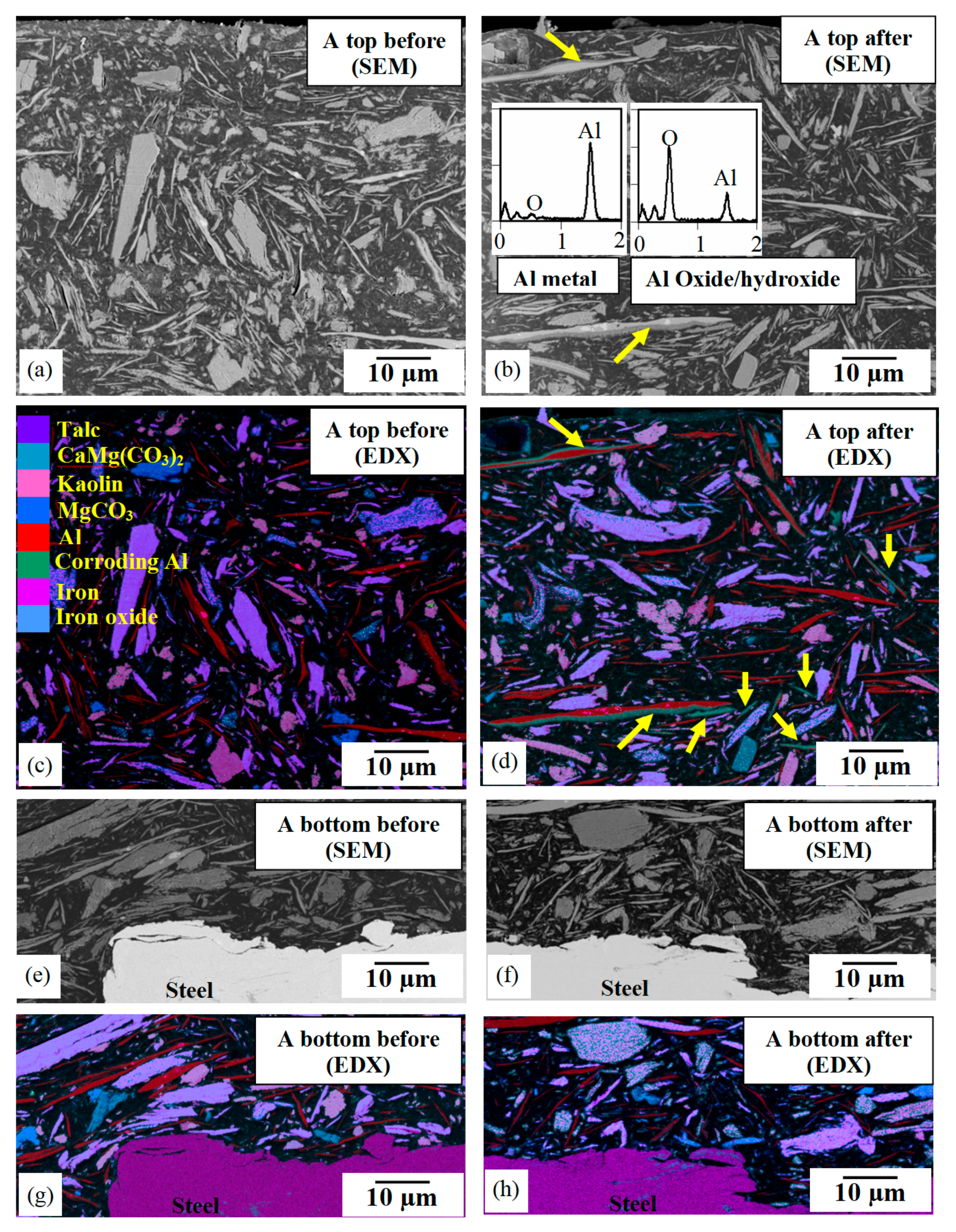
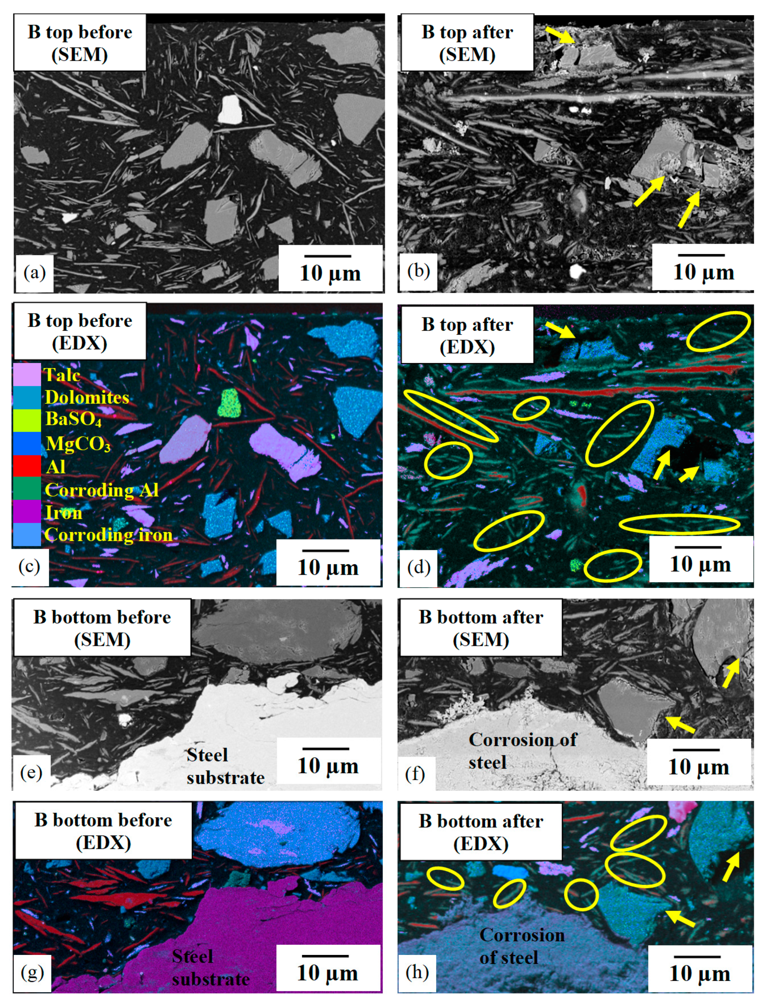
3.5.1. Pigment Analysis

Pigments used in the coating had nominally the same specification and were added in similar volume fractions but were from different suppliers. Flake aluminium pigments can always be unambiguously identified due to their lamellar morphology and were confirmed by analysis to be commercially pure aluminium. On the other hand, the inorganic ceramic pigment materials are naturally sourced and will have intrinsic variability. More detailed analyses were therefore carried out to confirm composition and to identify minor components.
Coating A (Figure 5) contained aluminium flakes, talc, and kaolin, consistent with the expected formulation. Pigments in coating B (Figure 6) were also consistent with the formulation but with significant quantities of dolomite and minor amounts of barium sulphate also present. In coating C (Figure 7), talc was the dominant pigment, with only minor amounts of kaolin and with minor amounts of dolomite as impurity.

3.5.2. Microstructural Damage

At the top surface of coating A before and after exposure (Figure 5a,c and Figure 5b,d, respectively), differing contrast is evident at the edges of flake pigments (Figure 5b, indicated by yellow arrows). EDX spot analyses confirmed that these pigments were aluminium metal with their edges enriched in oxygen (insert in Figure 5b). This is evidence of surface corrosion forming an aluminium oxide/hydroxide. The base of coating A adjacent to the steel substrate is imaged in Figure 5e,f, with EDS elemental maps in Figure 5g,h. At this location, no oxygen enrichment was found, and therefore, neither aluminium flakes nor the steel substrate were corroded.
Comparing the top surface regions of coating B before and after exposure (Figure 6), the dolomite contaminant had dissolved/fragmented after exposure, indicated by the yellow arrows in Figure 6b,d,f,h. Furthermore, the smaller aluminium metal flakes (coloured red in EDX maps) had corroded completely to aluminium hydroxide (green colour in the EDX maps) through the thickness to the base (oval areas in Figure 6d,h). Larger aluminium flakes were also corroded, but their cores remained in the metallic state. Significant corrosion of the steel substrate was observed after exposure, as can be seen in the SEM image (Figure 6f) and EDX map (Figure 6h).
Finally, coating C showed similar features as coating B but with the absence of dolomite (Figure 7). Thus, exposure with the smaller aluminium particles (≤10 µm) were almost entirely corroded (Figure 7d,e), while the larger flakes were surface corroded with their cores remaining metallic. Less corrosion damage was evident on the steel substrate (Figure 7f,h) compared with coating B.

3.6. Nanoscale X-Ray Tomography

Absorption contrast X-ray tomography relies on density and atomic number differences between sample components for visualisation. Thus, coating C was selected for tomography as it contained pigments easily identified by their distinct morphologies and densities. The sample region was taken approximately 30 µm below the surface and was used to investigate internal degradation (Figure 8). Segmentation of the image grey scales, with subsequent false colour assignments, allows the software to selectively emphasise or remove components of the 3D volume for imaging. For clarity, the grey scale representing the polymer binder is rendered transparent in order to reveal all the internal pigments (Figure 8a).
The flake aluminium pigments are false-colour-segmented (Figure 8b) to observe their spatial distribution and extent of corrosion. This shows that most aluminium pigments are orientated relatively parallel to the surface following application by the draw-down bar method. Also, the metallic aluminium (coloured light blue and indicated by red arrows) is surrounded by an oxide corrosion product layer. A grey-scale virtual cross-section of the sample with atomic number contrast is displayed (Figure 8c), which also reveals corroded aluminium at the flake edges and their intact metallic core with brighter contrast. This image is similar to the 2D scanning electron image shown in Figure 5a. The talc pigment particles were also false-colour-segmented (Figure 8d) and appear intact with no observable damage.
To observe the corrosion of flakes in more detail, individual aluminium pigments are singled out (Figure 8e,f), where metallic aluminium is blue and corroded aluminium is transparent dark green. In the top part of Figure 7e, the large aluminium flake is metallic in its core, whereas the smaller flakes in the figure are almost totally corroded. In Figure 8f, a substantial part of the aluminium flake is corroded around the edges. These images confirm that the corrosion of aluminium flakes initiated from the outer surface (edges) of pigments, progressing inwards.

4. Discussion

4.1. Coating Performance and Ranking

This research was originally intended to study whether different phenalkamine cross-linking agents or different coating application methods caused differences in anti-corrosion performance of a marine barrier coating. Accordingly, a comparison between coating A and coating B was intended to show performance differences between two phenalkamine cross-linkers. Similarly, a comparison between coating B and coating C should reveal whether coating application by airless spray or draw-bar causes differences in performance.
Unfortunately, post-exposure analyses revealed that the extender pigment packages, which were specified to be kaolin plus talc, were not consistent. Although one package was as expected (used in coating A), the second contained dolomite as a major impurity and barium sulphate as a minor impurity (used in coating B), while in the third package, talc was dominant, with dolomite also present as an impurity (used in coating C). Since analyses of the coatings occurred at the end of testing for both the exposed and control (unexposed) samples, this consistency problem was only discovered late in the research. However, we believe that, although unintended, the variation present provides additional insight into the corrosion protection of the formulated coatings. A summary of changes within the coatings and their performance is given in Table 3, with further discussion following.

4.2. Alignment and Orientation of Pigments

Industrial coatings are invariably spray-applied in practice; however, draw-bar application is often used for coating laboratory test panels, with the expectation that the application method does not influence field performance. Barrier coating performance relies on a significant volume fraction of pigments with a flake/lamellar morphology, which work most effectively when aligned parallel with the substrate. Thus, draw-bar application tends to align flake pigments more effectively than spray application.
The coating cross-section revealed in Figure 4 shows no significant difference in orientation of the flake aluminium pigments between the coatings. Although there is a performance difference between coatings B and C, this cannot be related to the differences in pigment alignment and orientation. Therefore, for this barrier coating formulation, it can be confirmed that the coating application method is of little significance in terms of anti-corrosion performance.

4.3. Aluminium Flake Pigments

Aluminium flake pigments are added to marine barrier coatings to enhance resistance to cathodic disbonding where anodes are present. The mechanisms proposed for this effect include consumption of cathodically produced hydroxide (i.e., pH buffering) and boosting of the physical barrier [19,20,21,22,23] Additionally, enhancement of mechanical resilience by stiffness reinforcement is reported [24]. In this current formulation, the aluminium pigments are effectively isolated from each other and from the substrate, so no galvanic interaction is possible with steel.
Figure 5, Figure 6 and Figure 7 and particularly the tomographic images in Figure 8, confirm that the corrosion of the aluminium starts and progresses from the flake exteriors inwards. There is no evidence of localised corrosion on the flakes, which appear to have corroded relatively uniformly. Furthermore, the aluminium corrosion products retain good adhesion with both the metallic aluminium side and the polymeric binder side without significantly damaging the physical or mechanical integrity of the coatings. Given the small size and volume fraction of the individual aluminium flakes, stresses arising in the polymer binder from corrosion volume expansion would be small in comparison to the volume changes due to different temperatures in the CCT cycle. Corrosion of the aluminium is impossible without an aqueous environment. Therefore, it can be concluded that corrosion damage of the flakes is direct evidence of environmental penetration during the hygro-thermal cyclic corrosion test.

4.4. Phenalkamine Cross-Linker

An infrared analysis of coatings revealed significant changes in relevant absorption bands associated with the thermoset network cross-linking. A peak from unreacted epoxy at 912 cm−1, consistent with the amine-to-epoxy stoichiometry, was evident in all coatings. For coating A (phenalkamine #1), Figure 3 shows this residual epoxy peak had decreased after CCT, which is consistent with the continued consumption of epoxy (and increased cross-linking) during the test [12,16,37]. Conversely, this decrease was not evident for coatings B and C (phenalkamine #2); however, a reduction in the ester band at 1734 cm−1 was seen, which is consistent with the hydrolysis of ester links during CCT [10,14]. Discolouration, reminiscent of phenolic oxidation, was apparent after exposure but only for coatings prepared using phenalkamine #2. From this, it can be concluded that the phenalkamine #1 cross-linker was more stable/hydrophobic than the phenalkamine #2 variant under the test conditions.
The glass transition temperature of coating A increased by about 10 °C after 6 months CCT, which is consistent with the infrared analysis showing decreased epoxy functionality and supports the interpretation that the cyclic corrosion test encourages greater network cross-linking, resulting in a lower free volume in the binder and reduced environmental ingress. On the other hand, for coatings B and C, glass transition temperatures decreased by around 8 °C after 6 months. This is also consistent with the infrared data where ester cross-links were seen to have hydrolysed. For these coatings, CCT induces network breakdown and increases free volume and environmental permeability.
Overall, these changes suggest that the polymer binder in coatings B and C is less stable than in coating A and becomes more open/permeable to water over time. Consequently, this facilitates easier electrolyte/ion/environment transport through the polymer to the metallic aluminium flake pigments and the steel substrate, resulting in the earlier onset of corrosion damage.

4.5. Inconsistency in Extender Pigments

Mineral extender pigments of talc and kaolin were specified for all coatings, and microscopy reveals variations in size and shape of the pigment particles. However, it was only later, after cross-section analytical microscopy, that differences in appearance and composition of the pigments were realised. As the three coatings were mixed and applied separately, it is assumed that pigments sourced from three different suppliers were used in the formulations.
Pigments were present in a largely flake-like morphology, in coating A, but with a smaller aspect ratio (i.e., shorter and wider) compared with aluminium flakes. However, in coatings B and C, some pigments were flaky, while some had a more globular appearance. Where present, talc and kaolin were found to be effectively unchanged after CCT and therefore possess high levels of stability contributing to the coating barrier properties.
A material analysis for coating A revealed the expected amounts of talc and kaolin (Figure 5). However, a significant volume fraction of dolomite (magnesium carbonate) was present in coating B (Figure 6), presumably arising as a contaminant in the natural mineral. Also present was barium sulphate, perhaps as an accidental contaminant. In comparison, the pigments in coating C had lower levels of dolomite and no barium sulphate (Figure 7). After CCT, dolomite and barium sulphate particles were partially dissolved and fragmented, particularly in coating B. This created pathways for easier ingress of the environment, resulting in increased corrosion of the steel substrate and the aluminium flake pigments. Figure 2b (coating B) shows increased absorption in the water band (3385 cm−1) compared with coatings A and C, which supports this hypothesis.

5. Conclusions

  • Three similar barrier-type marine ballast tank coatings, differing in phenalkamine curing agent, method of application, and extender pigments, were evaluated by analytical microscopy and spectroscopy before and after 6 months of hygro-thermal cyclic corrosion testing (CCT). Significant differences were observed in anti-corrosion performance, which can be related to the properties of the binder and pigments.
  • Based on the evidence provided in this study, there was little difference in flake pigment orientation, whether the coating was applied by airless spray or by draw-down bar. This suggests, for these coatings at least, that draw-down bar-applied laboratory coatings may be used to reflect the performance of spray-applied coatings, but this needs to be assessed on a case-by-case basis.
  • Where the environment had penetrated into the coating, varying amounts of corrosion damage to the steel substrate and of the aluminium flake pigments were revealed by cross-sectional microscopy. As aluminium flakes were isolated from each other and from the substrate, galvanic protection was absent in this system. High-resolution studies of individual flakes failed to detect any localised attack, and aluminium therefore appeared to corrode relatively uniformly. Volume expansion by the generation of an aluminium corrosion product did not appear to disrupt the binder/pigment interface.
  • It is confirmed that the polymer binder cross-link density and its environmental resistance is influenced by the stability of the phenalkamine curing agent. Thus, the more stable cross-linker had an increased Tg with no corrosion evident after CCT. Conversely, the less stable cross-linker had a decreased Tg with substrate and flake aluminium corrosion observed.
  • Where present, sparingly soluble contaminants (e.g., dolomite and barium sulphate) in the extender pigment increased water uptake into the coating and diminished its barrier protection.

Author Contributions

Conceptualization, S.L. and T.B.; methodology, D.B. and X.Z.; validation, Y.L., S.M., T.H. and R.E.; investigation, Y.L., R.E. and L.C.; resources, D.B., C.D.L., N.H. and P.I.; data curation, Y.L., L.C. and T.H.; original draft preparation, Y.L., L.C. and S.L.; review and editing, S.L.; visualization, Y.L., L.C. and T.H.; supervision, T.B., X.Z. and S.L.; project administration, T.B., X.Z. and S.L.; funding acquisition, S.L. All authors have read and agreed to the published version of the manuscript.

Funding

This research was funded by the UK Engineering and Physical Sciences Research Council and AkzoNobel, under grant number EP/S004963/1 (Sustainable Coatings by Rational Design).

Data Availability Statement

Original research data is available on reasonable request from the corresponding author.

Conflicts of Interest

The authors declare no conflicts of interest.

References

  1. Reed, C.; Eliasson, J. Coatings Cracking in Water Ballast Tanks: A Different Look. In NACE—International Corrosion Conference Series, Proceedings of the Corrosion Conference and Expo 2017, New Orleans, LA, USA, 26–30 March 2017; Volume 3, pp. 1928–1935.
  2. Iannarelli, P.; Beaumont, D.; Liu, Y.; Zhou, X.; Burnett, T.L.; Curioni, M.; Lyon, S.B.; Gibbon, S.R.; Morsh, S.; Emad, S.; et al. The degradation mechanism of a marine coating under service conditions of water ballast tank. Prog. Org. Coat. 2022, 162, 106588. [Google Scholar] [CrossRef]
  3. Song, E.; Lee, S.; Lee, H.; Kim, D. Effect of Coating Formulation on Crack Resistance of Epoxy Coatings. In NACE—International Corrosion Conference Series; NACE: Philadelphia, PA, USA, 2011; p. 11033. [Google Scholar]
  4. Oriaifo, E.; Perera, N.; Guy, A.; Leung, P.S.; Tan, K. A review of test protocols for assessing coating performance of water ballast tank coatings. Int. J. Mech. Aerosp. Ind. Mechatron. Manuf. Eng. 2014, 8, 1691–1696. [Google Scholar]
  5. 87 IACS Recommendation, Guidelines for Coating Maintenance & Repairs for Ballast Tanks and Combined Cargo/Ballast Tanks on Oil Tankers. Available online: https://www.iacs.org.uk/resolutions/recommendations/81-100/rec-87-rev2-cln/ (accessed on 20 December 2024).
  6. The Maritime Safety Committee (MSC); International Maritime Organization (IMO). RESOLUTION MSC.215(82): Performance Standard for Protective Coatings for Dedicated Seawater Ballast Tanks in All Types of Ships and Double-Side Skin Spaces of Bulk Carriers. 2006. Available online: https://www.imo.org/en/OurWork/Safety/Pages/ProtectiveCoatings.aspx (accessed on 20 December 2024).
  7. Eliasson, J.; Rauta, D.; Gunner, T. Ballast water tank coatings for the future. In Corrosion 2005; OnePetro: Richardson, TX, USA, 2005. [Google Scholar]
  8. EU Regulation (EC) No 1907/2006 “Registration, Evaluation, Authorisation and Restriction of Chemicals (REACH)”. Available online: https://echa.europa.eu/regulations/reach/legislation (accessed on 20 December 2024).
  9. Sakashita, S.; Shiotani, K.; Kashima, K.; Murakoshi, S.; Fukunaga, K.; Baba, T.; Takai, A.; Takada, A.; Osawa, N. Onboard study on deterioration of coated steel in water ballast tank. In Proceedings of the Twenty-Fifth International Ocean and Polar Engineering Conference, Kona, HI, USA, 21–26 June 2015; OnePetro: Richardson, TX, USA, 2015. [Google Scholar]
  10. Morsch, S.; Liu, Y.; Lyon, S.; Gibbon, S.; Gabriele, B.; Malanin, M.; Eichhorn, K.-J. Examining the early stages of thermal oxidative degradation in epoxy amine resins. Polym. Degrad. Stab. 2020, 176, 109147. [Google Scholar] [CrossRef]
  11. Morsch, S.; Emad, S.; Liu, Y.; Lyon, S.; Gibbon, S. Local oxidation of the buried epoxy-amine/iron oxide interphase. Prog. Org. Coat. 2021, 160, 106516. [Google Scholar] [CrossRef]
  12. Krauklis, A.E.; Echtermeyer, A.T. Echtermeyer, Mechanism of Yellowing: Carbonyl Formation during hygro-thermal ageing in a Common Amine Epoxy. Polymers 2018, 10, 1017. [Google Scholar] [CrossRef] [PubMed]
  13. Meiser, A.; Willstrand, K.; Possart, W. Possart, Influence of Composition, Humidity, and Temperature on Chemical ageing in Epoxies: A Local Study of the Interphase with Air. J. Adhes. 2010, 86, 222–243. [Google Scholar] [CrossRef]
  14. Lin, Y.C.; Chen, X.; Zhang, H.J.; Wang, Z.P. Effects of hygro-thermal ageing on epoxy-based anisotropic conductive film. Mater. Lett. 2006, 60, 2958–2963. [Google Scholar] [CrossRef]
  15. Ernault, E.; Richaud, E.; Fayolle, B. Thermal-oxidation of epoxy/amine followed by glass transition temperature changes. Polym. Degrad. Stab. 2017, 138, 82–90. [Google Scholar] [CrossRef]
  16. Rocha, I.B.C.M.; Raijmaekers, S.; Nijssen, R.P.L.; van der Meer, F.P.; Sluys, L.J. Hygro-thermal ageing behaviour of a glass/epoxy composite used in wind turbine blades. Compos. Struct. 2017, 174, 110–122. [Google Scholar] [CrossRef]
  17. Xiao, G.Z.; Shanahan, M.E.R. Irreversible Effects of hygro-thermal ageing on DGEBA/DDA Epoxy Resin. J. Appl. Polym. Sci. 1988, 69, 363–369. [Google Scholar] [CrossRef]
  18. Xiao, G.Z.; Delamar, M.A.; Shanahan, M.E.R. Irreversible Interactions Between Water and DGEBA/DDA Epoxy Resin During hygro-thermal ageing. J. Appl. Polym. Sci. 1997, 65, 449–458. [Google Scholar] [CrossRef]
  19. Reed, C. Underfilm Corrosion Creep and Cathodic Delamination: Under the Microscope. In Corrosion 2014; NACE International: Philadelphia, PA, USA, 2014; p. 4271. [Google Scholar]
  20. Knudsen, O.Ø.; Bardal, E.; Steinsmo, U. Effect of Barrier Pigments on Cathodic Disbonding Part 1: Aluminium and Glass Pigments. J. Corros. Sci. Eng. 1999, 2, 13. [Google Scholar]
  21. Knudsen, O.Ø.; Steinsmo, U. Effect of Barrier Pigments on Cathodic Disbonding Part 2: Mechanism of the Effect of Aluminium Pigments. J. Corros. Sci. Eng. 1999, 2, 37. [Google Scholar]
  22. Ramezanzadeh, B.; Khazaei, M.; Rajabi, A.; Heidari, G.; Khazaei, D. Corrosion Resistance and Cathodic Delamination of an Epoxy/Polyamide Coating on Milled Steel. Corrosion 2014, 70, 56–65. [Google Scholar] [CrossRef]
  23. Nikravesh, B.; Ramezanzadeh, B.; Sarabi, A.A.; Kasiriha, S.M. Evaluation of the corrosion resistance of an epoxy-polyamide coating containing different ratios of micaceous iron oxide/Al pigments. Corros. Sci. 2011, 53, 1592–1603. [Google Scholar] [CrossRef]
  24. Sato, K. The Internal Stress of Coating Films. Prog. Org. Coat. 1980, 8, 143–160. [Google Scholar] [CrossRef]
  25. Abil, E.; Arefinia, R. The influence of talc particles on corrosion protecting properties of polyurethane coating on carbon steel in 3.5% NaCl solution. Prog. Org. Coat. 2022, 172, 107067. [Google Scholar] [CrossRef]
  26. Katiyar, J.K.; Sinha, S.K.; Kumar, A. Friction and wear durability study of epoxy-based polymer(SU-8) composite coatings with talc and graphite as fillers. Wear 2016, 362–363, 199–208. [Google Scholar] [CrossRef]
  27. Dzulkafli, H.H.; Ahmad, F.; Ullah, S.; Hussain, P.; Mamat, O.; Megat-Yusoff, P.S. Effects of talc on fire retarding, thermal degradation and water resistance of intumescent coating. Appl. Clay Sci. 2017, 146, 350–361. [Google Scholar] [CrossRef]
  28. Abdel-Gaber, A.; Nabey, B.A.-E.; Khamis, E.; Abdelattef, O.; Aglan, H.; Ludwick, A. Influence of natural inhibitor, pigment and extender on corrosion of polymer coated steel. Prog. Org. Coat. 2010, 69, 402–409. [Google Scholar] [CrossRef]
  29. Ahmed, N.M.; Abdel-Fatah, H.T.M.; Youssef, E.A. Corrosion studies on tailored Zn·Co aluminate/kaolin core–shell pigments in alkyd based paints. Prog. Org. Coat. 2012, 73, 76–87. [Google Scholar] [CrossRef]
  30. Zhao, Q.; Zhao, X.; Jin, Z.; Wang, P.; Fan, L.; Deng, J.; Yuan, S.; Sun, Y.; Duan, J. Mechanism of an organic-inorganic composite coating with anticorrosive and versatile superhydrophobic properties: A combined electrochemical and molecular dynamics exploration. Prog. Org. Coat. 2023, 182, 107610. [Google Scholar] [CrossRef]
  31. Abid, M.; Khan, S.M.; Butt, M.T.Z. Investigation of Cathodic Protection, Morphological, Rheological, and Mechanical Properties of Graphene/Iron Oxide Nanoparticle-Embedded Cold Galvanizing Compounds at Reduced Pigment Volume Concentration. ACS Omega 2022, 7, 20556–20568. [Google Scholar] [CrossRef] [PubMed]
  32. ISO11357:2; Plastics—Differential Scanning Calorimetry (DSC); Part 2: Determination of Glass Transition Temperature and Step Height. ISO: Geneva, Switzerland, 2020.
  33. Bukalo, N.N.; Ekosse, G.I.E.; Odiyo, J.O.; Ogola, J.S. Fourier Transform Infrared Spectroscopy of Clay Size Fraction of Cretaceous-Tertiary Kaolins in the Douala Sub-Basin, Cameroon. Open Geosci. 2017, 9, 407–418. [Google Scholar] [CrossRef]
  34. Ngally Sabouang, C.J.; Mbey, J.A.; Liboum Thomas, F.; Njopwouo, D. Talc as raw material for cementitious products formulation. J. Asian Ceram. Soc. 2014, 2, 263–267. [Google Scholar] [CrossRef]
  35. Shameli, K.; Darroudi, M.; Bin Ahmad, M.; Yunis, W.M.Z.W.; Ibrahim, N.A. Synthesis and characterization of silver/talc nanocomposites using the wet chemical reduction method. Int. J. Nanomed. 2010, 5, 743–751. [Google Scholar] [CrossRef]
  36. Gokulakumar, B.; Nedunchezhian, G.; Vijayaraj, C.; Balamurugan, A. Fourier transform infrared spectroscopy studies on talcum powders. Int. J. Recent. Sci. Res. 2016, 7, 14505–14507. [Google Scholar]
  37. Odegard, G.M.; Bandyopadhyay, A. Physical ageing of Epoxy Polymers and Their Composites. J. Polym. Sci. Part B Polym. Phys. 2011, 49, 1695–1716. [Google Scholar] [CrossRef]
Figure 1. Optical microscopy of coating A (a,b), coating B (c,d), and coating C (e,f); left-hand images are before and right-hand images are after cyclic hygro-thermal corrosion testing.
Cmd 06 00001 g001
Figure 2. Wide spectrum FTIR analysis of coatings A (a), B (b), and C (c), before (broad dark line) and after (dotted or light line) cyclic corrosion testing. Annotated numbers on figures indicate peak positions in cm−1.
Cmd 06 00001 g002
Figure 3. Zoom FTIR spectra for coatings A (a,c) and C (b,d) before (broad dark line) and after (dotted or lighter line) cyclic corrosion testing in the regions around 912, 1654, and 1734 cm−1.
Cmd 06 00001 g003
Figure 4. Backscattered scanning electron images of coating cross-sections: A (a,b), B (c,d), and C (e,f). Image contrast is determined by relative local atomic number. Left-hand images are before and right-hand images are after exposure. Substrate corrosion was present in coatings B and C but not A.
Cmd 06 00001 g004
Figure 5. Coating A: high-resolution scanning electron with corresponding elemental maps from the top and bottom of the coating. Left-hand images (a,c,e,g) are before and right-hand images (b,d,f,h) are after corrosion testing. Yellow arrows point to corrosion damage on aluminium flakes.
Cmd 06 00001 g005
Figure 6. Coating B, high-resolution scanning electron images with corresponding elemental maps from the top and bottom of the coating. Left-hand images (a,c,e,g) are before and right-hand images (b,d,f,h) are after corrosion testing. Arrows indicate fragmented dolomite particles, and oval areas show corroded aluminium pigments; substrate corrosion is evident.
Cmd 06 00001 g006
Figure 7. Coating C, high-resolution scanning electron images with corresponding elemental maps from the top and base of the coating. Left-hand images (a,c,e,g) are before and right-hand images (b,d,f,h) are after corrosion testing. Dotted outlined areas show corroded aluminium flake pigments. Substrate corrosion is also observed.
Cmd 06 00001 g007
Figure 8. Three-dimensional X-ray nanoCT of coating C near the top surface: (a) flake aluminium pigments are aligned relatively parallel to the substrate; (b) corroded aluminium flakes with oxide on the exterior and retaining a metallic core (red arrows); (c) virtual cross-section using atomic number contrast similar to the cross-section shown in Figure 7b; (d) zoom on talc particles, which were largely intact and undamaged; (e,f) the corrosion damage of individual aluminium flakes can be quantified by comparing volume ratios of the residual metallic core and the oxide corrosion product.
Cmd 06 00001 g008
Table 1. Coating characteristics.
ApplicationCross-Linker“Active” PigmentExtendersPigment Fraction
Coating Asprayphenalkamine #1aluminium flakekaolin, talc28 ± 2%
Coating Bsprayphenalkamine #2aluminium flakekaolin, talc28 ± 2%
Coating Cdraw-downphenalkamine #2aluminium flakekaolin, talc28 ± 2%
Table 2. Tg before and after cyclic corrosion testing, measured by DSC.
CCT Exposure TimeTg
Coating AT = 0
T = 6 months
57 ± 1.5 °C
67 ± 1.5 °C
Coating BT = 0
T = 6 months
63 ± 1.5 °C
56 ± 1.5 °C
Coating CT = 0
T = 6 months
63 ± 1.5 °C
52 ± 1.5 °C
Table 3. Summary of coating changes after cyclic hygro-thermal corrosion testing.
Coating A
(Phenalkamine #1, Spray)
Coating B (Phenalkamine #2, Spray)Coating C (Phenalkamine #2, Draw Bar)
Binder stability(a) Tg increase; (b) binder cross-linking increase; (c) binder hydration(a) Tg decrease; (b) binder chain scission; (c) binder hydration and oxidation(a) Tg decrease; (b) binder chain scission; (c) binder hydration and oxidation
Al flake pigmentsvery minor corrosionsignificant corrosionsome corrosion
Pigment composition and stabilitykaolin + talc: stablekaolin + talc: stabletalc: stable
Impurity composition and stabilitynone identifieddolomite + barium sulphate: unstabledolomite: unstable
Substrate steel corrosionno corrosion~20 µm corrosion depth~10 µm corrosion depth
Disclaimer/Publisher’s Note: The statements, opinions and data contained in all publications are solely those of the individual author(s) and contributor(s) and not of MDPI and/or the editor(s). MDPI and/or the editor(s) disclaim responsibility for any injury to people or property resulting from any ideas, methods, instructions or products referred to in the content.

