Article

Carbonation-Induced Corrosion of Reinforced Concrete Elements according to Their Positions in the Buildings

by
Pascual Saura Gómez
1,*,
Javier Sánchez Montero
2,
Julio Emilio Torres Martín
2,
Servando Chinchón-Payá
2,
Nuria Rebolledo Ramos
2 and
Óscar Galao Malo
3
1
Department of Architectural Constructions, University of Alicante, 03690 Alicante, Spain
2
Instituto Eduardo Torroja de Ciencias de la Construcción (IETcc-CSIC), Calle de Serrano Galvache, 4, 28033 Madrid, Spain
3
Department of Civil Engineering, University of Alicante, 03690 Alicante, Spain
*
Author to whom correspondence should be addressed.
Corros. Mater. Degrad. 2023, 4(3), 345-363; https://doi.org/10.3390/cmd4030018
Submission received: 3 April 2023 / Revised: 15 June 2023 / Accepted: 19 June 2023 / Published: 21 June 2023

Abstract

:
Most regulations on the manufacturing of concrete for reinforced concrete structures rest on durability models that consider the corrosion of reinforcements. Those models are based on factors such as humidity, frost, presence of chlorides, and internal characteristics of the concrete itself, like resistance, porosity, type of cement, water/cement ratio, etc. No regulations, however, adopt a purely constructive perspective when evaluating the risk of corrosion, i.e., the relative position of the reinforced concrete in buildings. The present work focuses on the relationship between the position of the damaged element and the building envelope. A total of 84 elements (columns and reinforced concrete beams) across twenty buildings were analysed in the provinces of Alicante and Murcia (Spain). The reinforcement concrete of these elements underwent carbonation-induced corrosion according to their positions in the buildings: (A) façade columns in contact with the ground; (B) interior columns in contact with the ground; (C) columns of walls in contact with the ground; (D) columns and external beams protected from rain; (E) columns and external beams exposed to rain; (F) columns and beams in air chambers under sanitary slabs; and (G), columns and interior beams. Of all types, elements (E) and (F) suffered carbonation-induced corrosion faster than the models used in the regulations, and type (G) underwent slower carbonation.

1. Introduction

1.1. Concrete and Corrosion

The concrete coating of reinforced concrete provides a suitable medium of protection owing to its thickness and alkalinity. The high alkalinity of concrete (pH above 13) is due to the hydroxides of sodium, potassium, and especially calcium formed in the hydration reactions of cement silicates. These substances ensure the passivation of the reinforcements, which are oxide coated, forming a compact layer that keeps them protected [1].
Concrete carbonation [2,3,4,5] and chlorides [6,7] are the two major triggering factors of corrosion. These conditions are aggressive: they weaken the protective coating, allowing corrosion to occur before the minimum duration of the expected useful life has elapsed. The consequences can sometimes be serious [8].
The useful life of a structure corresponds to the period of time during which the conditions of safety, stability, functionality, and aesthetics defined in the project are preserved. Tuutti [9] elaborated a model that distinguishes two periods: corrosion initiation [10], corresponding to the time it takes for aggressive agents (carbonation or chlorides) to reach the reinforcement and depassivate it, and the propagation period [11,12], which is the time it takes for the reinforcement to oxidise when unprotected, until reaching an unacceptable state as it no longer meets the minimum conditions of the project (safety, stability, functionality, and aesthetics). This service life concept can be valid for any type of pathology that affects the service structure. In the case of reinforced concrete corrosion, however, service life will be defined according to a limit, i.e., a value that will, in turn, depend on project factors (type of structural element, safety coefficients, risks affecting safety) [11,13,14,15].

1.2. Carbonation

The reaction takes place via concrete pores in an aqueous solution and can be described as in [15,16]:
C O 2 + Ca ( OH ) 2 CaCO 3 + H 2 O
The carbonation reaction begins in the outer layer of the concrete coating and produces a low pH front that advances as the diffusion and reaction of CO2 take place. Carbonated concrete can be detected by applying an alcoholic solution of phenolphthalein to a newly extracted sample of the element to be studied. The latter will turn to pink in basic environments (pH greater than 13), and to a greyish colour corresponding to the concrete itself in the carbonate zone. Phenolphthalein can cause serious health problems, so stains composed of harmless indicators can also be applied. The latter include solutions with curcumin [17]; in this case, a reddish colour indicates that the concrete has not been carbonated, or solutions with anthocyanins [18], natural pigments from flowers and fruits that vary from blue to green depending on the pH—also in the range of mortar and concrete carbonation processes.
The diffusion of CO2 decreases over time, and therefore, so does the carbonation rate, because the penetration of the aggressive agent is hindered by the area previously carbonated. The penetration of carbonation is mathematically expressed as follows [9,19,20,21]:
c = K C O 2 t n
where c is the carbonation depth (mm), and t is the time (years). The carbonation coefficient KCO2 (mm/year1/n) measures the carbonation rate of penetration based on given environmental conditions and characteristics of the concrete. The carbonation rate may vary over time according to the parabolic formula. The carbonation rate tends to be negligible after a certain time in highly waterproof types of concrete as well as in very humid environments, n > 2. In most cases, it can be considered that n = 2, so c = KCO2· t .
The carbonation rate depends on both environmental factors (humidity, carbon dioxide concentration, and temperature) and concrete-related factors (mainly alkalinity and permeability) [20,21,22].
Humidity. Humidity is the most decisive carbonation rate factor. At constant relative humidity, the carbonation rate can be calculated according to the model in the literature [4,23], which sets maximum carbonation at humidities of 60–90%, decreasing to minimum carbonation levels outside that range.
CO2 concentration. The atmosphere in rural environments presents low carbon dioxide concentration rates (0.03%). Those of urban environments are much higher (0.1%). However, very high carbon dioxide concentrations may be present in some areas of the building. The higher the concentration of CO2 in the air, the higher the carbonation rate [2,4,24].
Temperature. Higher temperatures increase corrosion speed because they favour the movement of ions. A lower temperature, however, can produce condensation and consequently higher humidity levels, which is the most decisive corrosion factor.
Concrete quality. The composition of the concrete and its manufacturing process will provide the element with the intrinsic characteristics below that will also influence the carbonation process:
Water/cement ratio. If the w/c ratio decreases, the cement paste porosity and capillarity will be lower, and therefore the carbonation penetration process will be slower and more difficult [24]. This ratio is related to the characteristic strength of concrete, which increases if the w/c ratio decreases.
Characteristic resistance, fck. These data are highly indicative of concrete quality in terms of its alkalinity and, therefore, protection of the reinforcement. Indeed, a low w/c ratio implies greater amounts of cement of greater strength and higher pH.
Porosity. Concrete permeability greatly influences the carbonation rate because it facilitates the diffusion of carbon dioxide. The coating is the most likely layer to lose the curing water by evaporation, so insufficient curing will lead to greater coating porosity and, therefore, poor reinforcement protection [25].
Type of cement. When the cement paste has high alkalinity, the concrete can fix a greater amount of carbon dioxide. The hydration of pozzolanic materials or slag, therefore, leads to a higher corrosion rate [26].
Recent studies confirm that carbonation is not the direct cause of corrosion, but it favours its development under certain conditions of Ca(OH)2 loss, pH decrease, presence of H2O, CO2, and the other factors mentioned above [27].

1.3. Norm Codes

Reinforced concrete started to be regulated in Spain in 1939 with the IH-39 Instruction for the Design and Execution of Concrete Works [28]. The norm was then reviewed by a Commission—which the Eduardo Torroja Institute is part of—and the IH-44 was approved [29]. Subsequently, the Special Instruction for reinforced concrete structures HA-58 and HA-61—elaborated by the Eduardo Torroja Institute of Construction and Cement—came into force, followed by the Standards for Concrete Elements EH-68 [30], EH-73 [31], EH-80 [32], and EH-82 [33]. The minimum coating defined in the first regulation was 10 mm and increased to 15 mm in 1968. Different types of environments started to be considered from the EH-88 [34] and EH-91 [35] Standards onwards, and a minimum coating of 20 mm was defined. In all cases, the characteristic strength of concrete and the water/cement ratio were limited. With the entry into force of EHE-98 [36] and EHE-08 [37] on Structural concrete elements, a minimum characteristic strength of 25 N/mm2 (HA-25) was defined for concrete in reinforced concrete elements.
Current legislation, i.e., the Structural Code [19], is based on the European standard “Eurocode 2: Design of concrete structures” [38]. The service life of building structures and other common structures is 50 years, which will be directly affected by the corrosion of their reinforcements. The Structural Code and Eurocode 2 consider different types of exposure relating to the environmental conditions of structural concrete: no risk of corrosion attack (X0); carbonation-induced corrosion (XC); chloride-induced corrosion of non-marine origin (XD); chloride-induced corrosion of marine origin (XS); freeze/thaw attack (XF); chemical attack (XA); and erosion (XM). Regarding the environmental conditions of carbonation-induced corrosion, the following exposure classes are distinguished: XC1 (dry or permanently wet environments), XC2 (humid or rarely dry), XC3 (moderate humidity), and XC4 (cyclic dryness and humidity) [19].

1.4. Objectives

All models that analyse the corrosion rate of concrete reinforcement in concrete elements undergoing carbonation consider the factors mentioned above. Nevertheless, no regulations have hitherto examined corrosion in relation to the type of structural element and its position relative to the outer building envelope (contact with the ground, façade, and/or roof) [39,40,41,42,43].
The main objective of this study was to analyse the evolution of the apparent carbonation coefficient defined in the Structural Code and its relationship with the real carbonation coefficient in each case. To do so, we compared the data obtained according to the building element position, considering this position as a significant variable that has hitherto been overlooked.

2. Methodology

2.1. Buildings and Construction Elements Studied

Twenty buildings in south-eastern Spain were analysed, most of them in the province of Alicante and one in the province of Murcia. In all cases, the concrete reinforcements had suffered carbonation-induced corrosion. Chloride corrosion was not considered because none of the analysed elements showed any presence of Cl ions, or their proportion was negligible. Figure 1 shows the location of the buildings studied (listed in the supplementary material).
The complete list of buildings and sketches taken in situ is provided as attached documentation. They allow us to identify the position of the elements studied with respect to the construction envelopes.
All the buildings analysed in this study had been subjected to professional interventions in a project which used tests performed by Quality Control laboratories approved by the Generalitat Valenciana as starting data. In all cases, columns and beams were analysed in different positions of buildings for which information on building age was available, from its construction date to the test date. The tests described below were conducted.

2.2. Variable According to the Location of the Element in the Building

In this study, we considered 7 different element positions, according to the material characteristics of the element, based on the construction solutions that we could consider homogeneous in each case. We selected the different position variables according to the singular points of the elements in relation to the construction solutions of the building envelope systems and which were in contact with the outside. In accordance with Spain’s Technical Building Code, the construction systems of all building envelopes consist of the floors and walls in contact with the ground, the façades, and the roofs.
Therefore, a series of variables were defined, which we regarded as qualitative, since they were interpreted according to the relative quality of the position of the structural element analysed with respect to other construction systems of the building. The latter were as follows:
  • Façade columns in contact with the ground
  • Interior columns in contact with the ground
  • Wall columns in contact with the ground
  • External columns and beams protected from rain
  • External columns and beams exposed to rain
  • Columns and beams in air chambers beneath sanitary slabs
  • Interior columns and beams
These elements are illustrated in the diagram below, which defines all possible positions of the different structural elements with respect to the envelope (red line) in a building (Figure 2).
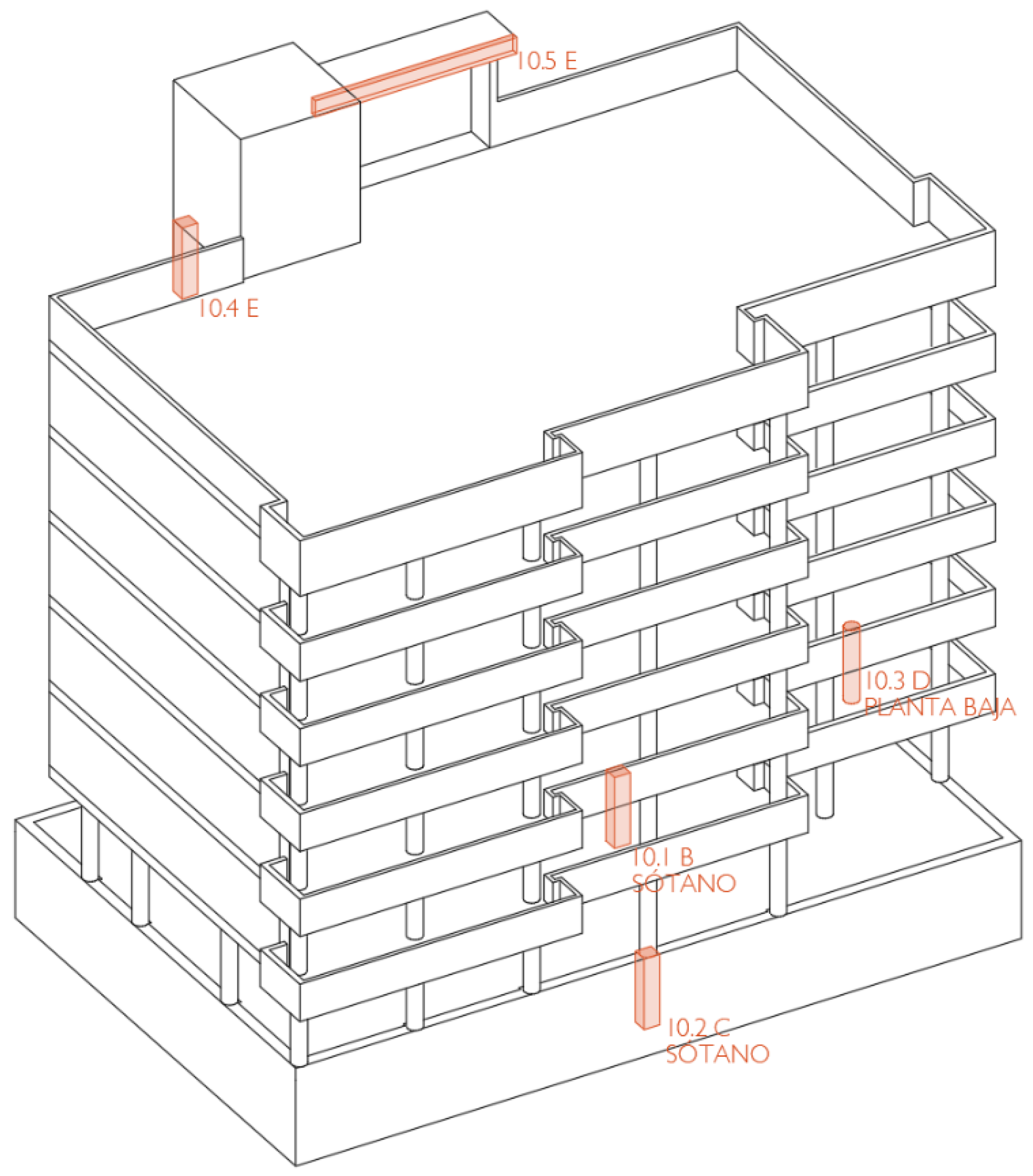
The 84 reinforced concrete elements (columns and beams) were identified by means of sketches drawn up in situ and other graphic documentation. Figure 3 below, corresponding to building number 10, is an example.

2.3. Testing

In the experimental phase, we compiled the laboratory data, which served as the basis for the studies and repair projects. They are described below.
Tests of the characteristic strength of concrete. For all 84 elements of the twenty buildings under study, each approved laboratory proceeded to extract a core sample in accordance with the UNE-EN 12504-1 and UNE-EN 12390-3 Standards. A 75 mm diameter rotating probe was used to determine the compressive strength of the concrete. In some cases, non-destructive tests were conducted to measure the speed of ultrasound propagation in elements of the same building. The objective was to determine their resistance based on a comparative study using the samples tested for compression.
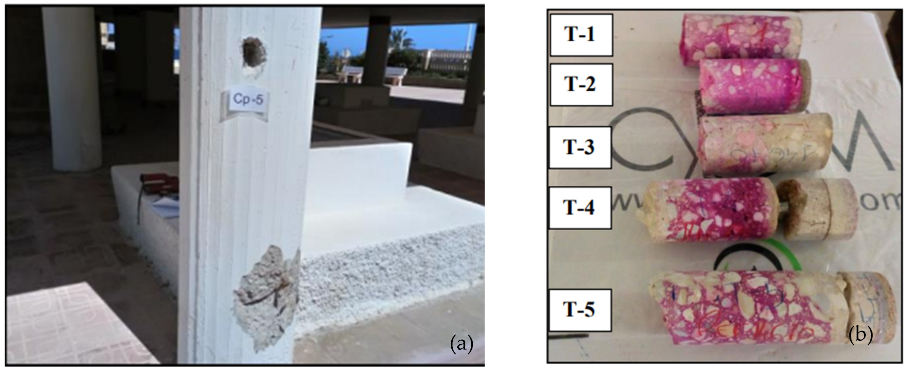
Carbonation depth test, sampling the reinforced concrete element, used the same core sample as the basis for the previous test or drilling in the element using a mechanical drill by rotation and applying a solution of 1% phenolphthalein in 95° ethanol alcohol. This solution is a pH indicator that turns pink in basic zones (pH above 8.5) when the concrete is not carbonated. In the most acidic areas where carbonation occurred, the sample remains colourless. This test consists of a mere visual inspection (Figure 4).
Determination of chloride content. The presence of chlorides in all samples was analysed to verify their absence in order to discard any potential chloride corrosion and to focus the study on carbonation.
Concrete coating. The measurements were taken with a flexometer. Data were similar to the minimum coatings contemplated in the project. When measurements were impossible to obtain, the authors considered the data provided by the project.
Diameter of the reinforced concrete. Both the longitudinal and transverse reinforcements were measured using a calliper.
Age of the building. All buildings were linked to the professional experience of one of the authors in collaboration with the laboratories involved. All buildings were between 9 and 60 years old. The building age was obtained from the data collected in the original project and the documentation provided by the property owners.
Both the concrete coating and the reinforcement diameter were used to verify whether the carbonation had reached the steel and, therefore, whether corrosion had begun.

2.4. Calculation of Kap,carb, and KCO2—Models and Statistical Processing

2.4.1. Calculation of Kap,carb

The Structural Code apparent carbonation coefficient Kap,carb expressed in mm/year1/2 was calculated using Equation (3).
K a p , c a r b = C e n v · C a i r · a · ( f c k + 8 ) b
where
Cenv = Environment coefficient, which is 1 if the element is protected from rain, 0.5 if it is exposed, 0.3 if it is buried above the water table, and 0.2 if it is buried below the water table. Table A12.3.1.a. of the Structural Code.
Cair = Coefficient of use of air entrainment. Concretes with less than 4.5% of occluded air have Cair of 1; concretes with more or equal to 4.5% of occluded air have Cair of 0.7 (Table A12.3.1.b) of the Structural Code.
a, b = Dimensionless parameters, which depend on the type of cement. Portland cement (a = 1800; b = −1.7); Portland cement + 28% fly ash (a = 360; b = −1.2); and Portland cement + 9% silica smoke (a = 400; b = −1.2), according to Table A12.3.1.c of the Structural Code.
fck = Characteristic concrete strength.

2.4.2. Calculation of KCO2

The real carbonation coefficient KCO2 of the analysed element is the result of relating its true carbonation depth (c) and the element age (t) by means of Equation (4).
K C O 2 = c t
where
KCO2 = Real carbonation coefficient in mm/year1/2.
c = Real carbonation depth of the analysed element in mm.
t = Real time of the analysed element in years.

2.4.3. Models and Statistical Processing

To develop the models and statistical processing, we used the calculated K and the qualitative variables defined above ((1) environment variable of the Structural Code defined in Section 1.3 and (2) position variable defined in Section 2.2).
We studied the correlation between all the data and variables mentioned and statistically assessed their inter-dependence. The software used for these studies was Excel and SPSS.

3. Results and Discussion

The data necessary to calculate the apparent carbonation coefficient Kap,carb according to the Structural Code model depend on the characteristic strength of the concrete element analysed, as well as the environment and air coefficients [19]. According to these data, we proceeded to calculate the Kap,carb based on the factors shown in the results table below.
We also calculated the real carbonation coefficient KCO2 of each element based on the building age and the results obtained from the carbonation depth of the element.
The relationship was calculated using Kap,carb, and KCO2, KCO2/Kap,carb. This helped us to understand the real carbonation processes in each environment as well as the positions of the elements analysed, comparing the real KCO2 carbonation (based on the measurement of the carbonation depth with respect to building age) and the theoretical Kap,carb carbonation according to the Structural Code model.
In addition, two qualitative variables were introduced. The first was XC1, XC2, XC3, and XC4 (according to the environments defined in the Structural Code [19]). The XC0 variable was not considered because all elements analysed belonged to real buildings and structures whose environments were not totally dry. The second series of variables, called A, B, C, D, E, F, and G, were based on the position of the element in the building relative to the building envelope. The latter constitutes a new line of study on the exposure of reinforced concrete elements to agents and factors that influence their carbonation, which may induce corrosion.
These results were transferred to Figure 5, which shows the carbonation coefficients (the real, KCO2, and the Code model, Kap,carb) ordered according to the characteristic strength of the concrete element fck. A decreasing tendency can be observed as the characteristic resistance of the element increases.
Based on the data presented in Figure 5 above, we discuss the results independently for each studied variable below.

3.1. Results of the XC Variable

The sample was heterogeneous and encompassed 84 elements across 20 different buildings. We, therefore, present the results by analysing the theoretical and real carbonation coefficients in the four classified environments of carbonation-induced corrosion in accordance with the Structural Code, i.e., in cases XC1, XC2, XC3, and XC4. We did not consider the XC0 environment, since it did not apply to any of the building elements studied. The results were ordered according to the influence of the greater characteristic strength of concrete fck as a determining factor of adequate carbonation behaviour (the higher the fck, the lower the theoretical Kap,carb and real KCO2 carbonation coefficient).
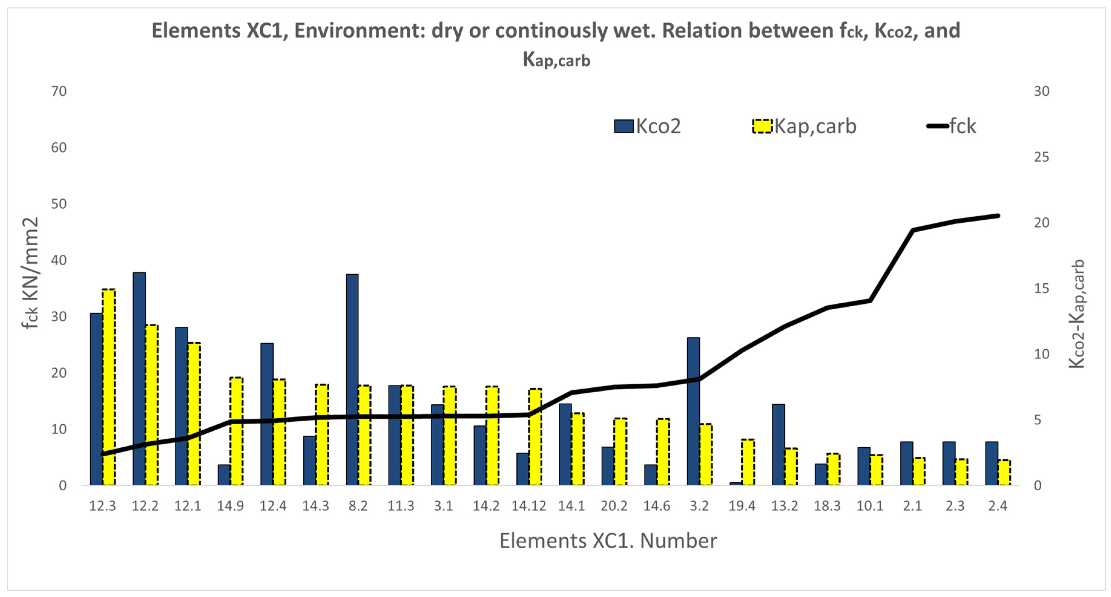
As shown in Figure 6, according to the model, carbonation varied in XC1 environments (i.e., dry or continuously wet) from 14.91 mm/ y e a r to 1.93 mm/ y e a r , with uniform behaviour with respect to fck. The real carbonation ranges from 16.20 mm/ y e a r to 0.20 mm/ y e a r . It corresponds to an interior column (element 19.4) and differs significantly from the model, with a much lower level of carbonation than expected.
For XC2 environments (wet and rarely dry), and according to Figure 7, the model carbonation drops with the increase in fck and ranges from 0.68 to 1.48 mm/ y e a r ; the data of the real carbonation (KCO2) present low and sometimes null values. They corresponded in all cases to structural elements (wall columns) in contact with the ground.
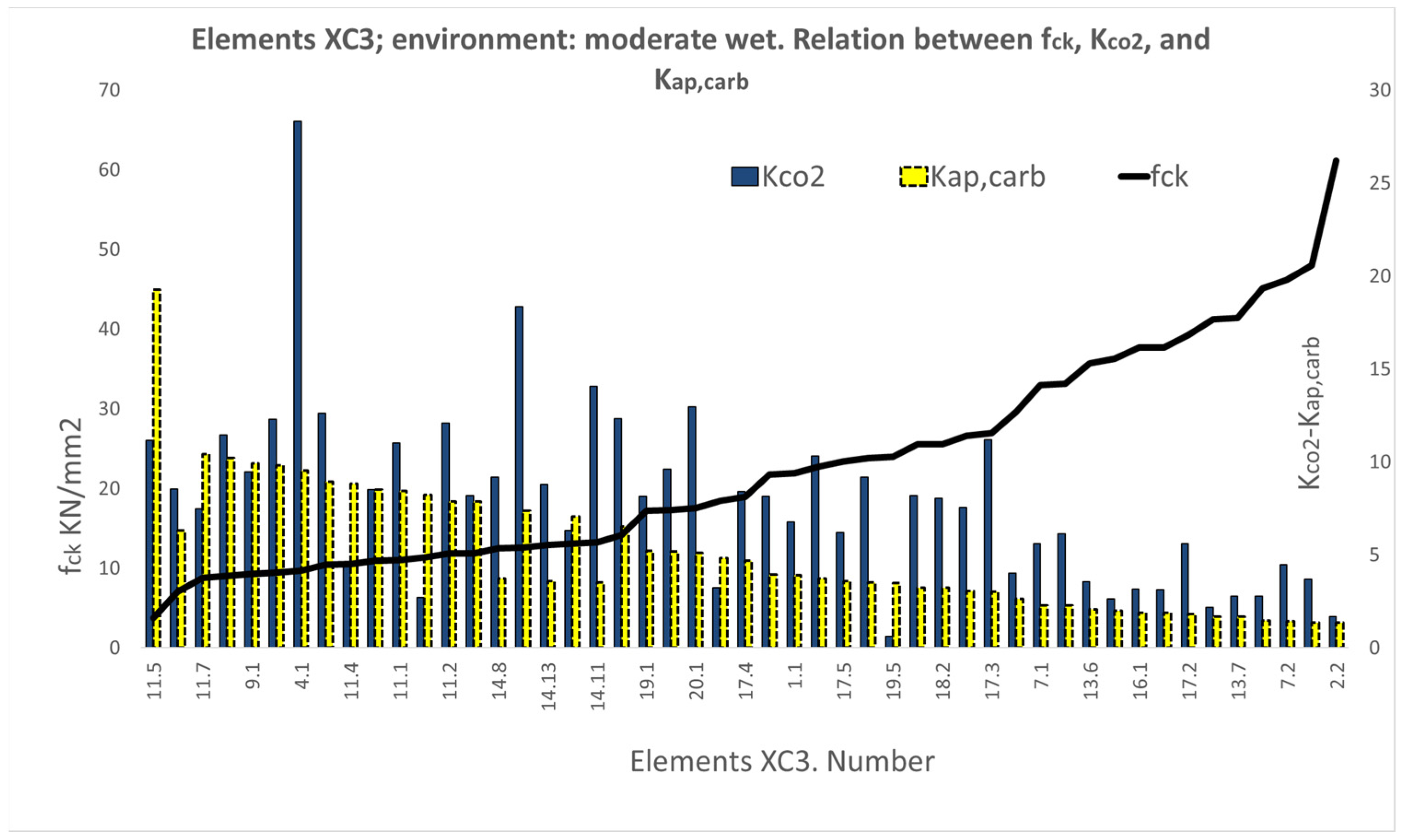
Figure 8 shows the results of 49 elements considered in XC3 environments (moderately wet) with relative humidity above 65%, that is, in the outer building envelope, but protected from rain. The same trend as in previous cases can generally be observed, but positions were also found in which there were significant variations between the real carbonation and that predicted by the Code, both above and below the theoretical values. The carbonation KCO2 reached 28.33 mm/ y e a r (element 4.1), a much higher value than the theoretical value. The lowest data of the real carbonation were at 0.61 mm/ y e a r (element 19.5), which is much lower than the theoretical value.
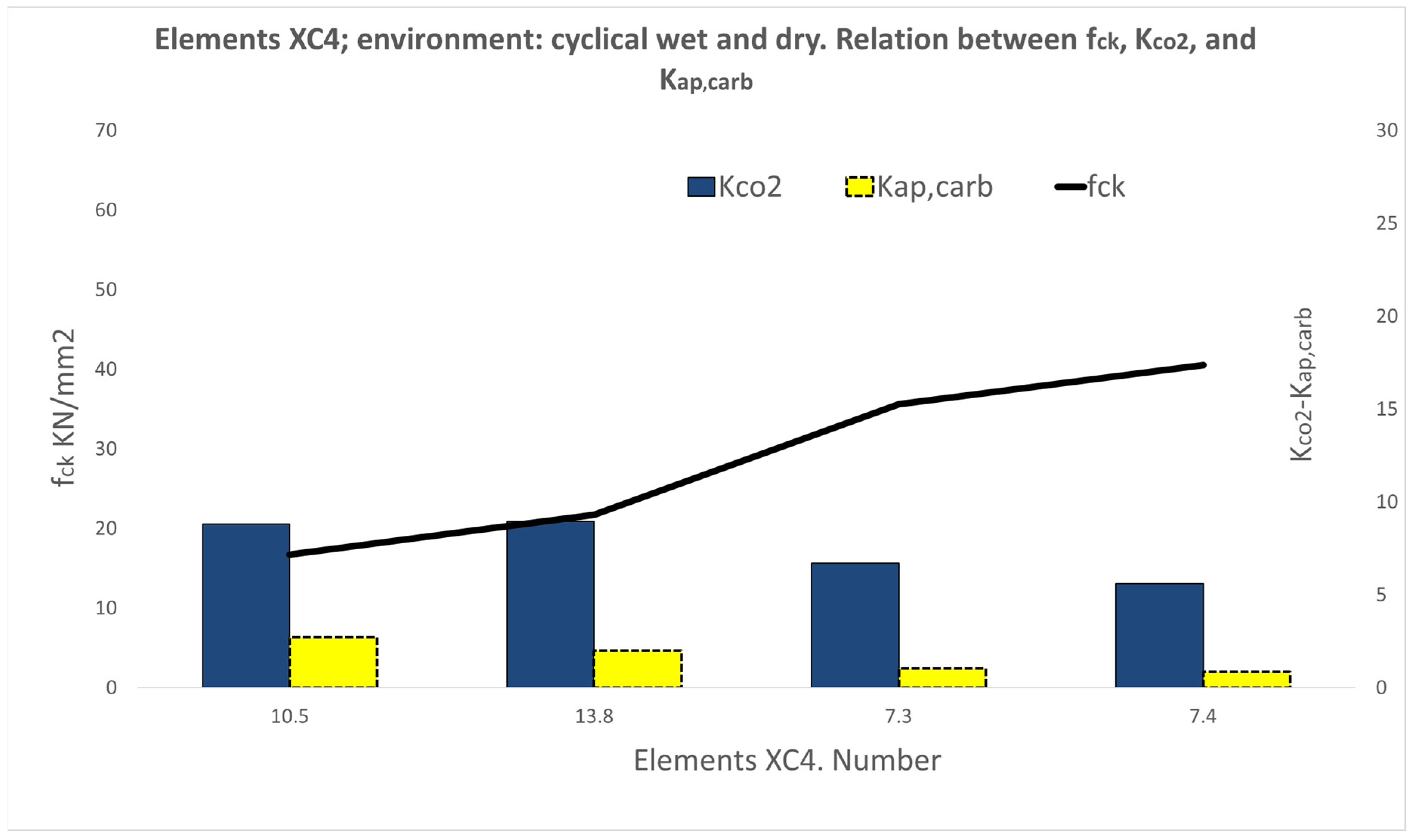
However, in the case of XC4 environments (wet and dry cycles), as shown in Figure 9, the real carbonation depths ranged between 5.59 and 8.95 mm/ y e a r , representing much higher values than the theoretical ones, expected to range between 0.86 mm/ y e a r and 2.70 mm/ y e a r .
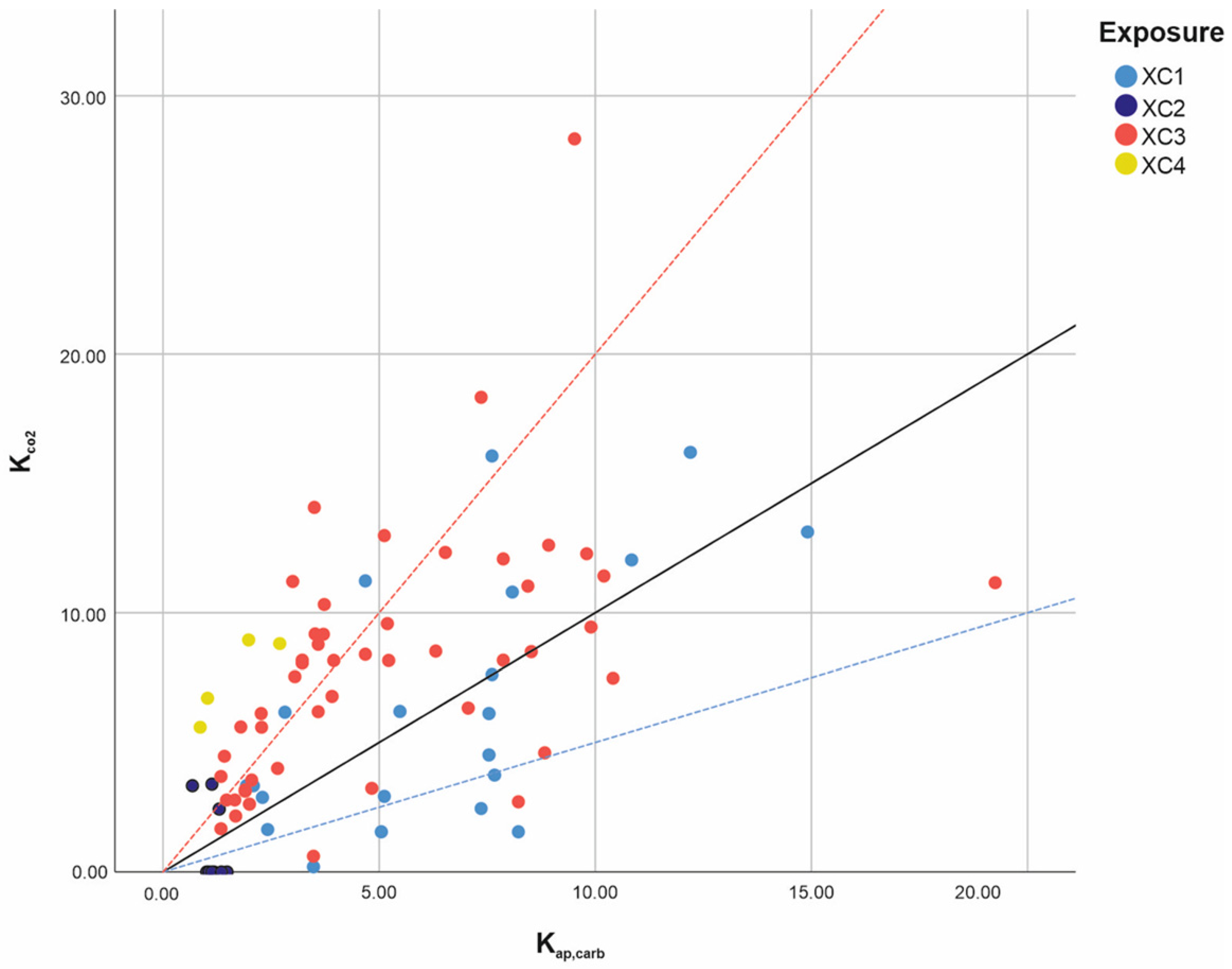
In all cases, there was a clear tendency of decreasing carbonation with increasing characteristic strength; however, this trend presented different levels of response according to the different environments considered by the standard. We, therefore, performed a comparative study of the real carbonation KCO2 coefficient and the theoretical Kap,carb, coefficient, as shown in Figure 10.
To establish a relationship between the carbonation data obtained in reality and that deriving from the models, we considered that the element carbonation represented in Figure 10 would approach an acceptable result if the values obtained ranged between half and double (represented as the lines y = 0.5x and y = 2x). The XC3 variable presented the largest number of values above the y = 2x line; however, the environment represented by XC4 led to the values furthest above the y = 2x line and, therefore, much higher real carbonation than expected. All of this explains the difficulties in obtaining accurate models based on the functions estimated by the Structural Code, especially with regard to the variables XC3 and XC4.
To complete the analysis, the statistical indicators (sample number N, median M, average x , and standard deviation σ, of the values KCO2/Kap,carb ratio obtained for the XC1, XC2, XC3, and XC4 variables are presented (Table 1), which help us to understand the results correctly and to consider them as acceptable.
We can confirm that the variables XC3 ( x = 1.82) and XC4 ( x = 5.20) offer the highest values of the KCO2/Kap,carb average (close to or greater than the straight line y = 2x), as shown in the graphical representation in Figure 10). The σ indicator shows the mean root squared errors and the complexity of the environment models.

3.2. Results of the Variable Series A, B, C, D, E, F, and G

The objective was to explore another variables that would help to forecast and thereby establish protection measures guaranteeing the greater durability of concrete structures for buildings. The results obtained according to the new variable defined in this study are presented below. They are based on the location of the elements analysed in the building; the comparison of the theoretical and real carbonation coefficients calculated independently; and the estimation of the seven possibilities analysed.
Type A elements are located on the building façade and in contact with the ground. They present moderate humidity since they are on the building’s skin, but they are protected from rain. We considered that the environments defined in the Structural Code would be included in XC3 environments. Figure 11 shows the results with a uniform decrease in Kap,carb, from values of 9.9 mm/ y e a r for the least resistant concretes, up to 1.34 mm/ y e a r for concretes with a greater fck. The real carbonation, KCO2, varied between 1.67 and 28.33 mm/ y e a r , and was always greater than the theoretical carbonation. One exception was element 11.4, which corresponds to a façade column protected by a cantilever on the ground floor of commercial premises.
Type B elements are interior columns on the ground floors (that start from the foundations). They are therefore protected and subject to low relative humidity. The trend was similar to the case A columns, with some elements presenting KCO2 < Kap,carb. Notable, however, is the example of element 19.4, with a real carbonation close to zero, i.e., much lower than expected. It corresponds to a ground floor interior column of the Teaching Centre. In this case, according to the Code, type B elements (Figure 12) can be considered to correspond to XC1 environments.
The columns and reinforced concrete walls in basement levels were considered to belong to type C, where foundation elements would also be included. In this case, the environment is humid since the concrete elements are permanently in contact with the ground, as in the XC2 environment elements of the Code. Very low carbonation was detected, and in some cases, it was null; these values, however, are close to those obtained with the theoretical models, as shown in Figure 13.
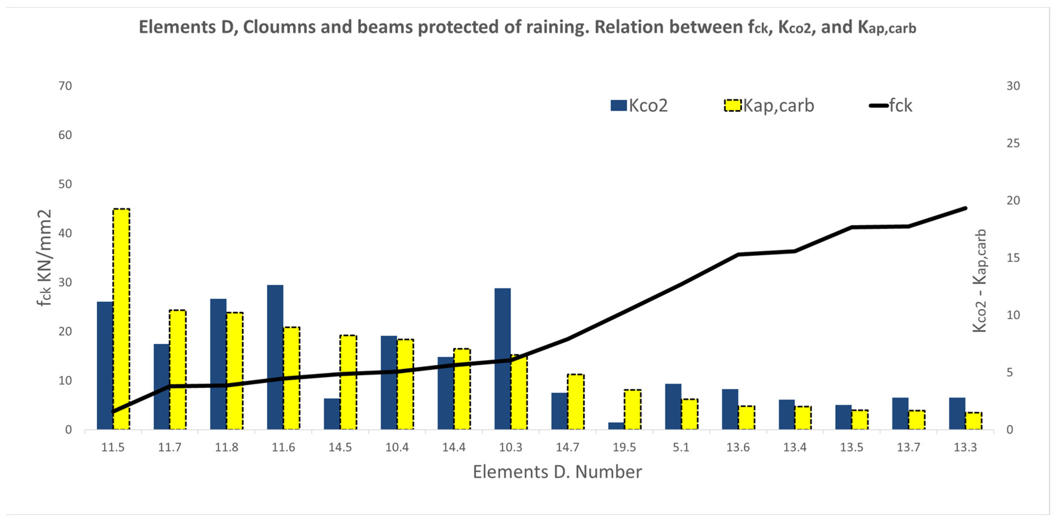
The D columns are located on the façades or exterior areas of the building, with the presence of moderate humidity, but are protected from rain, either by the envelope, or because the concrete elements are exposed but covered by the building. We can consider them as elements in XC3 environments sharing a similar trend as that of the cases above; carbonation decreases with the characteristic strength of concrete, and the real results are usually higher than the theoretical results. Very low carbonation is again found with respect to the theoretical carbonation level in the building element 19.5, with a value of KCO2 = 0.61 mm/ y e a r << Kap,carb = 3.48 mm/ y e a r , and in the building element 14.5, with a value of KCO2 = 2.71 mm/ y e a r < < 8.22 mm/ y e a r . The maximum value reached for KCO2 is 12.61 mm/ y e a r . These results are collected in Figure 14.
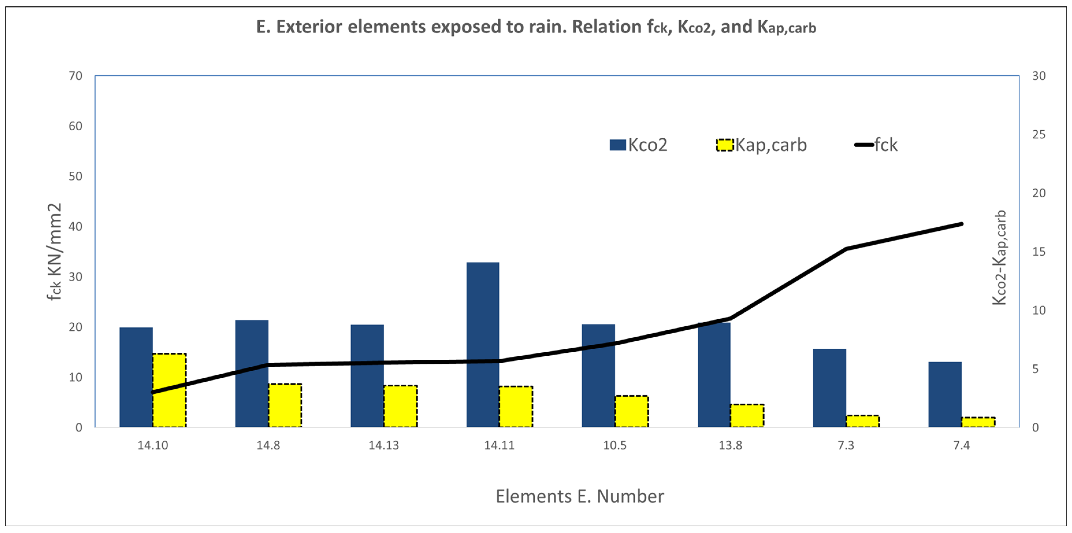
Type E elements are exterior beams and columns, which are unprotected and exposed to rain. These would clearly correspond to XC4 environments with wet and dry cycles. Theoretical models predict lower carbonation for more resistant elements in this case, while the results showed values of KCO2 >> Kap,carb, as shown in Figure 15.
The columns and beams found in the air chambers of sanitary slabs are type F. They can be regarded to correspond to type XC3 in the Structural Code because they are situated in building interiors with moderate humidity. As in the case of type E elements, the results obtained ranged from KCO2 >> Kap,carb, in most cases close to the double relationship, with KCO2 values ranging from 3.12 to 12.98 mm/ y e a r and Kap,carb between 1.34 and 5.22 mm/ y e a r , as shown in Figure 16.
The last studied position was type G, corresponding to columns and beams in interior environments that are totally disconnected from the building envelope (they are not in contact with the façade, roof, or floor). They correspond to XC1 dry environments, in closed rooms (isolated) with low air humidity, and normally have coatings to protect them from the environment. The carbonation results obtained were very low in all cases, from 1.55 to 2.92 mm/ y e a r , and they were always lower than those of the Code models, between 2.42 and 8.22 mm/ y e a r , as shown in Figure 17, with ratios close to 0.5 or below.
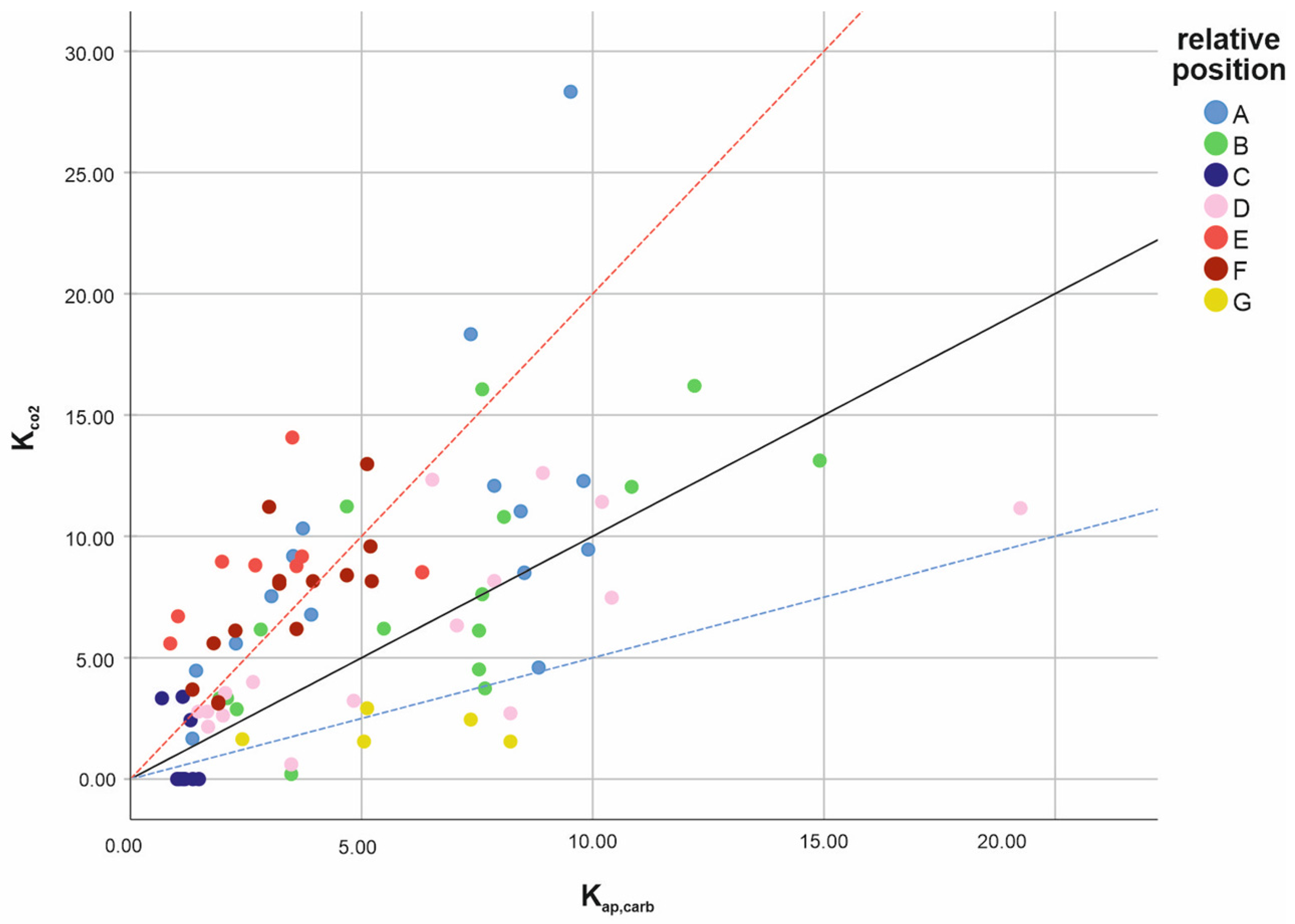
We proceeded to compare all the results described for the range of proposed variables A, B, C, D, E, F, and G across the 84 elements under study. The KCO2 value is represented on the ordinates axis and Kap,carb on the abscissa to study the degree of alignment and/or acceptance of the carbonation coefficient results obtained in reality and by applying the Structural Code recommended formulas. The data are represented in Figure 18 as greater than double (red dashed line y = 2x) in the case of positions E (beams and columns exposed to rain) and F (elements in sanitary air chambers). Moreover, elements in G-type positions (indoors, totally protected from the outside and separated from the envelope) offered values close to or less than 0.5 (blue dashed line y = 0.5x).
The indicators sample number N, median M, average x , and standard deviation σ, are now presented for the values of KCO2/Kap,carb ratio corresponding to the A, B, C, D, E, F, and G variables (Table 2) to complete the graphic study carried out and consider the results obtained as acceptable.
We can confirm that the variables E ( x = 3.89) and F ( x = 2.30) offer the highest values of the KCO2/Kap,carb average (close to or greater than the straight line y = 2x) and the values of G ( x = 0.42) are the lowest, close to the line y = 0.5x, as shown in the graphical representation in Figure 18. In general, the σ values decrease, particularly for G, although they remain high for the C and E variables.
Based on a comparative analysis of the Structural Code variable environments and the new qualitative variables under study here, we found that variables XC2 and XC4 corresponded to positions C and E, respectively. Elements exposed to XC1 environments corresponded to type B and G positions, and XC3 environments covered cover building positions A, D, and F. Table 3 shows this correlation and comparison of the different environments with the different positions defined in this study. The colours shown for each variable correspond to those shown in the figures (Figure 10 and Figure 18)

4. Conclusions

This work shows the difficulty of defining a durability model of reinforced concrete based on the depth of its carbonation. Figure 2 represents the drawing of the studied elements according to their position in relation to the building envelope, and Table 3 explains the relationship between the new A, B, C, D, E, F, and G variables, and the XC1, XC2, XC3, and XC4 Standard variables.
The carbonation results obtained for the building elements studied, KCO2 and Kap,carb, decreased with higher levels of the characteristic strength of concrete. However, when we studied the KCO2/Kap,carb ratio, a certain value dispersion was found (the standard deviation was from 0.20 to 1.89). The values tended to exceed the expected values because the KCO2/Kap,carb ratio average was between 1.09 and 5.20 (>1), except in the case of highly protected interior elements like type G with a 0.42 average (<1). The environments defined in the Structural Code are generic, and further specifications are required to better adjust the model to reality.
After exploring how to improve the durability models of reinforced concrete (XC1, XC2, XC3, and XC4) in the face of carbonation-induced corrosion, we proposed a new classification of element types A, B, C, D, E, F, and G according to their position in relation to the building envelope. These types reflect the Code environment more accurately. According to this study, type A elements (protected on the façade and in contact with the ground) presented a higher carbonation level than expected (the average ẋ of KCO2/Kap,carb = 1.90), which was quite acceptable in XC3 environment (moderate humidity and protected from rain) ( x = 1.82). The carbonation of type B elements ( x = 1.30) (interiors in contact with the ground) was similar to that predicted by the model in an XC1 environment ( x = 1.10) (low humidity). The behaviour of type C elements ( x = 1.09) (reinforced concrete elements in contact with the ground) corresponded to XC2 environments ( x = 1.09) (wet environments). The type D elements ( x = 1.14) in the outer envelope protected from rain presented a similar carbonation to that of the XC3 environment model ( x = 1.82). Type E elements ( x = 3.89) (exposed outdoors to rain) could be assimilated to XC4 environments ( x = 5.20) (wet and dry cycles) but presented much higher carbonation depths than in theory. Type F beams and columns ( x = 2.30) (in sanitary slab chambers) could be assimilated to the XC3 wet environment ( x = 1.82) and showed greater carbonation depths than in theory. Lastly, type G elements ( x = 0.42) (inside the building), in dry environments protected by coatings, presented minimal or no carbonation, i.e., lower levels than according to the model.
To conclude, the position of elements type E and type F presented a greater ratio of real carbonation than in the theoretical model and, thus, a greater level of corrosion than expected. However, indoor environments, type G, presented a more favourable trend. These results open a significant new line of research on the durability of elements located in positions E and F. A broader study could be performed on the variables in construction systems that connect with the structural system. Analyses could also be conducted on how this could affect the choice of solutions for singular points (meeting points, protection, developments, ventilation, etc.), taking into account exposure to aggressive conditions that generate this unfavourable carbonation behaviour. Moreover, the models for columns, slabs, and G-type beams could be reviewed. Indeed, the latter hardly requires any protection against carbonation as the environment inside the building guarantees greater durability.

Supplementary Materials

The following supporting information can be downloaded at: https://www.mdpi.com/article/10.3390/cmd4030018/s1, in the documentation presented, the elements under study were part of the following buildings: 1. Isolated block for residential use with a ground floor and four storeys in Águilas (Murcia). 2. Warehouse for office use and warehouse with a basement and two storeys in Rebolledo (Alicante). 3. Building between dividing walls with ground floor premises and four residential-use storeys in Dolores (Alicante). 4 Building between dividing walls with ground floor premises and four residential-use storeys in Guardamar del Segura (Alicante). 5. Building between dividing walls with ground floor, three storeys and penthouses in Torrevieja (Alicante). 6. Isolated block for semi-basement parking and three residential-use storeys in La Mata-Torrevieja (Alicante). 7. Isolated block for residential use with ground floor and four storeys in La Mata-Torrevieja (Alicante). 8. Building between dividing walls with ground floor premises and first floor residential-use in Dolores (Alicante). 9. Building between dividing walls of ground floor premises and two residential-use storeys in Rojales (Alicante) 10. Isolated block of basement parking, diaphanous ground floor and five residential-use storeys in El Altet-Elche (Alicante). 11. Building between dividing walls with ground floor premises and four residential-use storeys in Alicante. 12. Building between dividing walls with basement parking, ground floor premises and five residential-use storeys in Alicante. 13. Isolated block with basement parking, diaphanous ground floor and fifteen residential-use storeys in Alicante. 14. Isolated block for tourist use with basement parking, ground floor and five storeys in Alicante. 15. Water tank in Alicante. 16. Isolated residential block with ground floor and five storeys in Alicante. 17. Isolated block for residential use with ground floor and ten storeys in Alicante. 18. Secondary School in Catral (Alicante). 19. José Granero Early Childhood Education School in Santa Pola. 20. Ramón Cuesta de Santa Pola Early Childhood Education School.

Author Contributions

Conceptualization, P.S.G. and Ó.G.M.; methodology, P.S.G.; software, P.S.G. and S.C.-P.; validation, P.S.G., J.S.M., J.E.T.M., N.R.R., S.C.-P. and Ó.G.M.; formal analysis, P.S.G. and J.S.M.; investigation, P.S.G.; resources, P.S.G. and J.S.M.; data curation, P.S.G. and J.E.T.M.; writing—original draft preparation, P.S.G.; writing—review and editing, P.S.G. and S.C.-P.; visualization, J.E.T.M. and N.R.R.; supervision, J.S.M.; project administration, P.S.G.; funding acquisition, J.S.M. All authors have read and agreed to the published version of the manuscript.

Funding

This research was funded by the European Union-Next Generation EU grant number reference RECUALI 21-08 (Requalification of the Spanish University System 2021–2023).

Data Availability Statement

Data is contained within the article or supplementary materials.

Acknowledgments

This work was possible thanks to the collaboration and contribution of work documentation from the contractor company VNP Lesiones y Patologias del Hormigón S.L, represented by Pedro Carlos Ferrández. Quality Control Laboratories: Intecom SAL, Cytem, Levatec, and Horysu. The author, Pascual Saura, wishes to thank the University of Alicante, the Ministry of Universities, and the European Union for the financial support of the Requalification of the Spanish University System 2021–2023 granted for the Stay at the Instituto Eduardo Torroja de Ciencias de la Construcción (research group on Reinforcement Corrosion and Structural Safety), where the present study was performed.

Conflicts of Interest

The authors declare no conflict of interest.

References

  1. Pourbaix, M. Thermodynamics and Corrosion. Corros. Sci. 1990, 30, 963–988. [Google Scholar] [CrossRef]
  2. Al-Kadhimi, T.K.H.; Banfill, P.F.G.; Millard, S.G.; Bungey, J.H. An Accelerated Carbonation Procedure for Studies on Concrete. Adv. Cem. Res. 1996, 8, 47–59. [Google Scholar] [CrossRef]
  3. Chávez-Ulloa, E.; Pérez López, T.; Reyes Trujeque, J.; Corvo Pérez, F.; Osorno Carrillo, J.B. Carbonatación de concreto en atmósfera natural y cámara de carbonatación acelerada. Rev. CENIC Cienc. Químicas 2010, 41. ISSN: 1015-8553. Available online: https://www.redalyc.org/articulo.oa?id=181620500029 (accessed on 2 April 2023).
  4. Ho, D.W.S.; Lewis, R.K. Carbonation of Concrete and Its Prediction. Cem. Concr. Res. 1987, 17, 489–504. [Google Scholar] [CrossRef]
  5. Alonso, C.; Andrade, C. Life Time of Rebars in Carbonated Concrete. In Proceedings of the 10th European Corrosion Congress—Progress in the Understanding and Prevention of Corrosion, Barcelona, Spain, 31 May–4 June 1993; Volume 1, pp. 634–641. [Google Scholar]
  6. Chen, C.; Liu, R.; Zhu, P.; Liu, H.; Wang, X. Carbonization Durability of Two Generations of Recycled Coarse Aggregate Concrete with Effect of Chloride Ion Corrosion. Sustainability 2020, 12, 10544. [Google Scholar] [CrossRef]
  7. Geng, J.; Liu, J.; Yan, J.; Ba, M.; He, Z.; Li, Y. Chemical Composition of Corrosion Products of Rebar Caused by Carbonation and Chloride. Int. J. Corros. 2018, 2018, 7479383. [Google Scholar] [CrossRef] [Green Version]
  8. Sanchez, J.; Fullea, J.; Andrade, C. Corrosion-Induced Brittle Failure in Reinforcing Steel. Theor. Appl. Fract. Mech. 2017, 92, 229–232. [Google Scholar] [CrossRef]
  9. Tuutti, K. Corrosión of Steel in Concrete. Ph.D. Thesis, KTH Royal Institute of Technology, Stockholm, Sweden, October 1982. [Google Scholar]
  10. Kim, C.; Choe, D.-E.; Castro-Borges, P.; Castaneda, H. Probabilistic Corrosion Initiation Model for Coastal Concrete Structures. Corros. Mater. Degrad. 2020, 1, 328–344. [Google Scholar] [CrossRef]
  11. Otieno, M.B.; Beushausen, H.D.; Alexander, M.G. Modelling Corrosion Propagation in Reinforced Concrete Structures—A Critical Review. Cem. Concr. Compos. 2011, 33, 240–245. [Google Scholar] [CrossRef]
  12. Andrade, C.; Menéndez, E.; Lima, L.; Luchtenberg, C. Vida Útil de la Estructuras de Hormigón. Proyecto y Modelización; Fundación Rogelio Segovia para el Desarrollo de las Telecomunicaciones: Madrid, Spain, 2013. [Google Scholar]
  13. Andrade, C.; Menéndez, E.; Lima, L.; Villagrán, Y.; Luchtenberg, C. Diseño Prestacional para la Durabilidad de Estructuras de Hormigón Armado. Vida Útil de Estructuras Existentes. Monitoreo, Intervención y Rehabilitación; Fundación Rogelio Segovia para el Desarrollo de las Telecomunicaciones: Madrid, Spain, 2013. [Google Scholar]
  14. Torres Martín, J.E.; Rebolledo Ramos, N.; Chinchón-Payá, S.; Helices Arcila, I.; Silva Toledo, A.; Sánchez Montero, J.; Otero García, F.; Llorente Sanjuán, M.; Agulló Soto, S.; de Haan, L. Durability of a Reinforced Concrete Structure Exposed to Marine Environment at the Málaga Dock. Case Stud. Constr. Mater. 2022, 17, e01582. [Google Scholar] [CrossRef]
  15. Galan, I.; Sanchez, J.; Andrade, C.; Evans, A. Carbonation Profiles in Cement Paste Analyzed by Neutron Diffraction. J. Phys. Conf. Ser. 2012, 340, 12108. [Google Scholar] [CrossRef]
  16. Galán, I.; Perdrix, C.A.; Castellote, M.; Rebolledo, N.; Sánchez-Montero, J.; Toro, L.; Puente-Orench, I.; Campo, J.; Fabelo, O. Neutron Diffraction for Studying the Influence of the Relative Humidity on the Carbonation Process of Cement Pastes. J. Phys. Conf. Ser. 2011, 325, 012015. [Google Scholar] [CrossRef]
  17. Chinchón-Payá, S.; Andrade, C.; Chinchón, S. Indicator of Carbonation Front in Concrete as Substitute to Phenolphthalein. Cem. Concr. Res. 2016, 82, 87–91. [Google Scholar] [CrossRef]
  18. Chinchón-Payá, S.; Andrade, C.; Chinchón, S. Use of Anthocyanin Solutions in Portland Cement Concrete to Identify Carbonation Depth. Mater. Struct./Mater. Constr. 2020, 53, 4–9. [Google Scholar] [CrossRef]
  19. Código Estructural, Real Decreto 470/2021. 2021. (In Spanish). Available online: https://www.boe.es/eli/es/rd/2021/06/29/470 (accessed on 2 April 2023).
  20. Yoon, I.-S.; Chang, C.-H. Time Evolution of CO2 Diffusivity of Carbonated Concrete. Appl. Sci. 2020, 10, 8910. [Google Scholar] [CrossRef]
  21. Garces, P.E. Procesos de Degradación Físico-Químicos en Estructuras de Hormigón Armado; Publicacions Universitat Alacant: Alicante, Spain, 2021; ISBN 9788497177450. [Google Scholar]
  22. Stefanoni, M.; Angst, U.; Elsener, B. Corrosion Rate of Carbon Steel in Carbonated Concrete—A Critical Review. Cem. Concr. Res. 2018, 103, 35–48. [Google Scholar] [CrossRef]
  23. Parrott, L.J. Carbonation, Moisture and Empty Pores. Adv. Cem. Res. 1992, 4, 111–118. [Google Scholar] [CrossRef]
  24. Page, C.L.; Treadaway, K.W.J. Aspects of the Electrochemistry of Steel in Concrete. Nature 1982, 297, 109–115. [Google Scholar] [CrossRef]
  25. Balayssac, J.P.; Détriché, C.H.; Grandet, J. Effects of Curing upon Carbonation of Concrete. Constr. Build. Mater. 1995, 9, 91–95. [Google Scholar] [CrossRef]
  26. von Greve-Dierfeld, S.; Lothenbach, B.; Vollpracht, A.; Wu, B.; Huet, B.; Andrade, C.; Medina, C.; Thiel, C.; Gruyaert, E.; Vanoutrive, H.; et al. Understanding the Carbonation of Concrete with Supplementary Cementitious Materials: A Critical Review by RILEM TC 281-CCC. Mater. Struct./Mater. Constr. 2020, 53, 136. [Google Scholar] [CrossRef]
  27. Melchers, R.E.; Richardson, P.J. Carbonation, Neutralization and reinforcement corrosion for concrete in long-term atmospheric exposures. Corrosion 2023, 79, 395–404. [Google Scholar] [CrossRef]
  28. Ministerio de Obras Públicas. Orden de 3 de Febrero de 1939 Instrucción para el Proyecto y Ejecución de Obras de Hormigón; Ministerio de Obras Públicas: Madrid, Spain, 1939. [Google Scholar]
  29. Ministerio de Obras Públicas. Orden de 23 de Marzo de 1944 Instrucción Definitiva para el Proyecto y Ejecución de Obras de Hormigón; Ministerio de Obras Públicas: Madrid, Spain, 1944. [Google Scholar]
  30. Presidencia del Gobierno. Decreto 2987/1968 de 20 de Febrero Instrucción para el Proyecto y Ejecución de Obras de Hormigón en Masa y Armado; Presidencia del Gobierno: Madrid, Spain, 1968. [Google Scholar]
  31. Presidencia del Gobierno. Decreto 3062/1973 de 20 de Febrero Instrucción para el Proyecto y Ejecución de Obras de Hormigón en Masa o Armado. Instrucción EH-73; Presidencia del Gobierno: Madrid, Spain, 1973. [Google Scholar]
  32. Ministerio de Obras Públicas y Urbanismo. Real Decreto 2868/1980 de 17 de Octubre Instrucción para el Proyecto y Ejecución de Obras de Hormigón en Masa o Armado (EH-80); Ministerio de Obras Públicas y Urbanismo: Madrid, Spain, 1980. [Google Scholar]
  33. Ministerio de Obras Públicas y Urbanismo. Real Decreto 2262/1982 de 24 de julio Instrucción para el Proyecto y Ejecución de Obras de Hormigón en Masa o Armado (EH-82); Ministerio de Obras Públicas y Urbanismo: Madrid, Spain, 1982. [Google Scholar]
  34. Ministerio de Obras Públicas y Urbanismo. Instrucción para el Proyecto y Ejecución de Obras de Hormigón en Masa o Armado (EH-88); Ministerio de Obras Públicas y Urbanismo: Madrid, Spain, 1988. [Google Scholar]
  35. EHE-91 REAL DECRETO 1039/1991, de 28 de Junio, Por El Que Se Aprueba La «Instrucción Para El Proyecto y La Ejecución de Obras de Hormigón En Masa o Armado (EH-91)». 1991. Available online: https://www.boe.es/buscar/doc.php?id=BOE-A-1991-17068 (accessed on 2 June 2023).
  36. Ministerio de Fomento. Real Decreto 2661/1998 de 11 de Diciembre Instrucción de Hormigón Estructural (ECH-99); Ministerio de Fomento: Madrid, Spain, 1998. [Google Scholar]
  37. Ministerio de la Presidencia. Real Decreto 1247/2008 de 18 de Julio. Instrucción de Hormigón Estructural (EHE-08); Ministerio de la Presidencia: Madrid, Spain, 2008. [Google Scholar]
  38. EN 1992-1-1; European Standard Eurocode 2: Design of Concrete Structures-Part 1-1: General Rules and Rules for Buildings. European Committee for Standardization: Brussels, Belgium, 2004.
  39. Liu, X.; Niu, D.; Li, X.; Lv, Y.; Fu, Q. Pore Solution PH for the Corrosion Initiation of Rebars Embedded in Concrete under a Long-Term Natural Carbonation Reaction. Appl. Sci. 2018, 8, 128. [Google Scholar] [CrossRef] [Green Version]
  40. Sohail, M.G.; Laurens, S.; Deby, F.; Balayssac, J.P. Significance of Macrocell Corrosion of Reinforcing Steel in Partially Carbonated Concrete: Numerical and Experimental Investigation. Mater. Struct. 2013, 48, 217–233. [Google Scholar] [CrossRef]
  41. Sohail, M.G.; Laurens, S.; Deby, F.; Balayssac, J.P.; Al Nuaimi, N. Electrochemical Corrosion Parameters for Active and Passive Reinforcing Steel in Carbonated and Sound Concrete. Mater. Corros. 2021, 72, 1854–1871. [Google Scholar] [CrossRef]
  42. Bossio, A.; Faella, G.; Frunzio, G.; Guadagnuolo, M.; Serpieri, R. Diagnostic Reliability in the Assessment of Degradation in Precast Concrete Elements. Infrastructures 2021, 6, 164. [Google Scholar] [CrossRef]
  43. Wang, C. Explicitly Assessing the Durability of RC Structures Considering Spatial Variability and Correlation. Infrastructures 2021, 6, 156. [Google Scholar] [CrossRef]
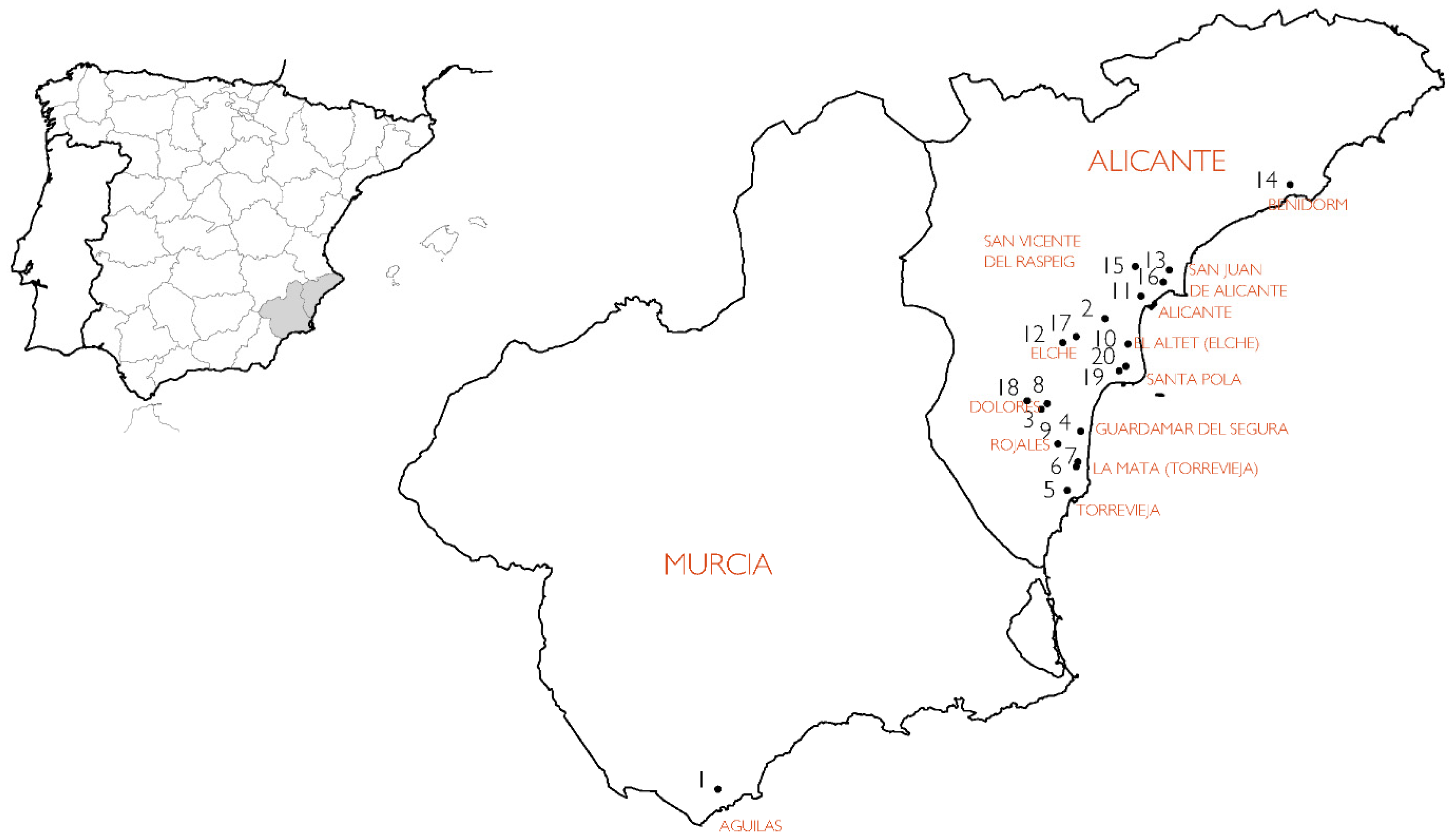
Figure 1. Map of south-eastern Spain indicating the locations of the buildings studied.
Cmd 04 00018 g001
Figure 2. Diagram of the relative position variable of the elements in the building.
Cmd 04 00018 g002
Figure 3. On-site data collection by means of an element identification sketch.
Cmd 04 00018 g003
Figure 4. (a) Core sample extraction and (b) testing with phenolphthalein solution (building 10).
Cmd 04 00018 g004
Figure 5. Results of KCO2 (real) and Kap,carb (model) ordered according to fck.
Cmd 04 00018 g005
Figure 6. Results of KCO2 and Kap,carb in XC1 environments.
Cmd 04 00018 g006
Figure 7. KCO2 and Kap,carb results in XC2 environments.
Cmd 04 00018 g007
Figure 8. KCO2 and Kap,carb results in XC3 environments.
Cmd 04 00018 g008
Figure 9. KCO2 and Kap,carb results in XC4 Environments.
Cmd 04 00018 g009
Figure 10. Representation of KCO2 (real carbonation)/Kap,carb (carbonation according to the Structural Code model) of the elements in environments XC1, XC2, XC3, and XC4.
Cmd 04 00018 g010
Figure 11. Position type A elements.
Cmd 04 00018 g011
Figure 12. Position type B elements.
Cmd 04 00018 g012
Figure 13. Position type C elements.
Cmd 04 00018 g013
Figure 14. Position type D elements.
Cmd 04 00018 g014
Figure 15. Position type E elements.
Cmd 04 00018 g015
Figure 16. Position type F elements.
Cmd 04 00018 g016
Figure 17. Position type G elements.
Cmd 04 00018 g017
Figure 18. Representation of KCO2/Kap,carb according to the variables A, B, C, D, E, F, and G.
Cmd 04 00018 g018
Table 1. Statistical indicators. KCO2/Kap,carb for the XC1, XC2, XC3, and XC4 variables.
Statistical Indicators. KCO2/Kap,carb
VariableNMedian = M Average = x Standard Deviation = σ
XC1221.061.100.66
XC290.001.091.80
XC3491.721.820.87
XC445.515.201.60
Table 2. Statistical indicators. KCO2/Kap,carb for the A, B, C, D, E, F, and G variables.
Statistical Indicators. KCO2/Kap,carb
VariableNMedian = M Average = x Standard Deviation = σ
A151.731.900.84
B171.251.300.61
C90.001.091.80
D161.201.140.54
E83.643.891.89
F142.282.300.65
G50.330.420.20
Table 3. Correspondence between the Structural Code environments and the element types studied. The colours shown for each variable correspond to those shown in the figures (Figure 10 and Figure 18).
Structural CodeVariables according to the Building Position
XC1BG
XC2C
XC3ADF
XC4E
Disclaimer/Publisher’s Note: The statements, opinions and data contained in all publications are solely those of the individual author(s) and contributor(s) and not of MDPI and/or the editor(s). MDPI and/or the editor(s) disclaim responsibility for any injury to people or property resulting from any ideas, methods, instructions or products referred to in the content.