Article

Safe Treatment of Surface Coalfield Fires Above Shallow-Buried Goaf in Steeply Dipping Coal Seams

1
School of Geology and Mining Engineering, Xinjiang University, Urumqi 830046, China
2
Xinjiang Baodi Mining Co., Ltd., Urumqi 830048, China
3
No. 156 Coalfield Geological Exploration Team, Xinjiang Uygur Autonomous Region Coalfield Geological Bureau, Urumqi 830047, China
4
Xinjiang Yaxin Coal Bed Gas 156 Exploration Co., Ltd., Urumqi 830049, China
*
Author to whom correspondence should be addressed.
Submission received: 10 December 2024 / Revised: 13 January 2025 / Accepted: 15 January 2025 / Published: 18 January 2025

Abstract

Xinjiang is a region of China that suffers severe energy resource loss and air pollution resulting from long-term coalfield fires in near-surface inclined coal seams. Beneath these fire areas, abandoned mined-out goaf is common. Accidents easily occur during the treatment of such fire areas owing to the instability of strata overlying the goaf. Here, we carried out non-destructive exploration of the goaf below a fire area using the airborne transient electromagnetic method, accurately identifying the locations and sizes of 21 goaf areas. We then established a stratigraphic model using the thermal-solid coupling function in UDEC software. Our simulations showed that under the combined action of high temperature generated by coal combustion and high pressure generated by fire-fighting machinery, the maximum displacement and vertical stress in strata overlying the goaf were 1.42 m and 36 MPa, respectively. Such large displacement and stress values inevitably lead to the destabilization of overlying strata via turning, sliding, and tipping, seriously threatening the safety of mining personnel and machinery. In the field, the rock layer above the goaf was first accurately blasted, and then fire extinguishing was carried out after the overlying rock had collapsed and compacted.

1. Introduction

At present, on the basis of the intrinsic combustion conditions and external factors of a given coal fire, various methods are employed both domestically and internationally to manage surface coal fires. These methods include covering with surface loess, drilling and water/gel injection, grouting, filling with inert gases to extinguish fires, stripping and removing the fire source, as well as integrated fire-fighting techniques [1,2,3]. Coal fire extinguishing technology is relatively mature.
Meanwhile, scholars have made progress in studying the stability of the overburden during the temperature-stress coupling process, mainly focusing on the field of underground coal gasification. Bajestani et al. [4] investigated long-term thermo–hydro–mechanical behavior in the near-field of a deep geological repository system and found that the stress distribution varied along with the temperature changing. Shao et al. [5] studied the long-term performance of nuclear waste repositories at micro-and macroscopic levels and found that crystal structure and/or crystalline aggregates were influenced greatly by temperature variation. Shang et al. [6] conducted mineral composition, pore structure, and mechanical characteristics of pyroxene granite exposed to heat treatments. Their results indicated that the high-temperature effect can be roughly identified as three stages: 25–500 °C, 500–800 °C, 800–1200 °C, In 800–1200 °C, quartz reacts chemically to produce the crystal state of the minerals, which deteriorate dramatically; the mechanical parameters of granite samples all change significantly, the uniaxial compressive strength (UCS) and the elastic modulus decrease by 81.30%, 81.20%, and 92.52%, respectively; the failure mechanism of granite samples transforms from quasi-brittle to plastic. Zhang et al. [7,8,9,10] studied high-temperature effects on the porosity, pore size, and pore morphology of various materials such as coal, sandstone, concrete, and limestone, using CT scanning electron microscope (CT-SEM), mercury intrusion porosimetry (MIP), micro-CT, low-field nuclear magnetic resonance (NMR), and ultrasonic velocity measurement (UVM). They obtained thermal damage and microcracks are induced by high temperature, and the law of thermal stress caused by thermal expansion of the overburden under the influence of high temperatures, which supports the upward movement of rock strata and reduces the amount of subsidence.
These results generally indicate that the strength and modulus of rock strata decrease with increasing temperature, and the corresponding bearing capacity and deformation resistance are rapidly decreased. The stability of the roof strata in the goaf is bound to decline due to the high temperature action of coal fire and the weight of the vehicle in surface fire fighting operations for a long time, which poses a threat to the safety of the coal fire extinguishing above the goaf.
Therefore, building upon the aforementioned studies, we here focus on the No. 1 fire area in the Chatekale Fire Area (Xingliang II Mine Field), Gaochang District, Xinjiang, because this area is characterized by long ignition history, high surface temperature, and difficulty in fire fighting. Utilizing methods including precise geophysical exploration, thermo-solid coupling numerical simulations, and field tests, we aim to investigate management techniques for coal fires above near-surface goaf in steeply dipping coal seams, with the ultimate goal of providing a robust reference for similar engineering management elsewhere.

2. Materials and Methods

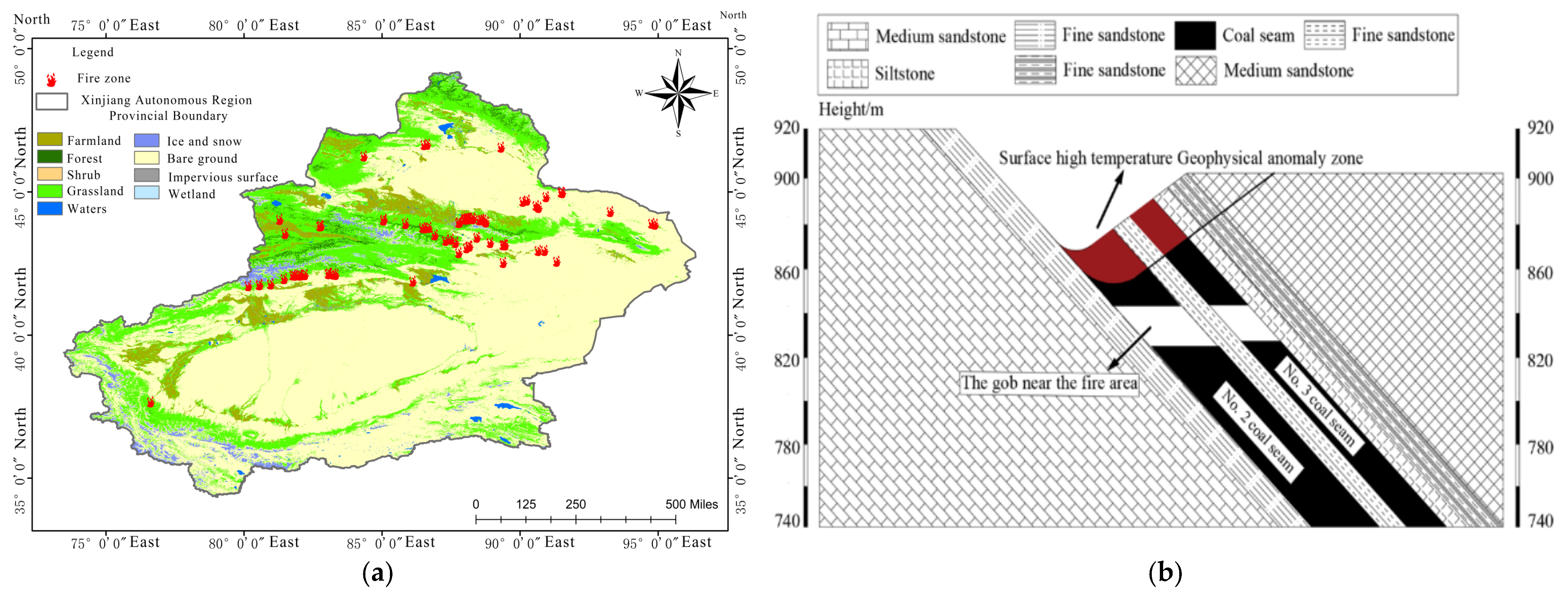
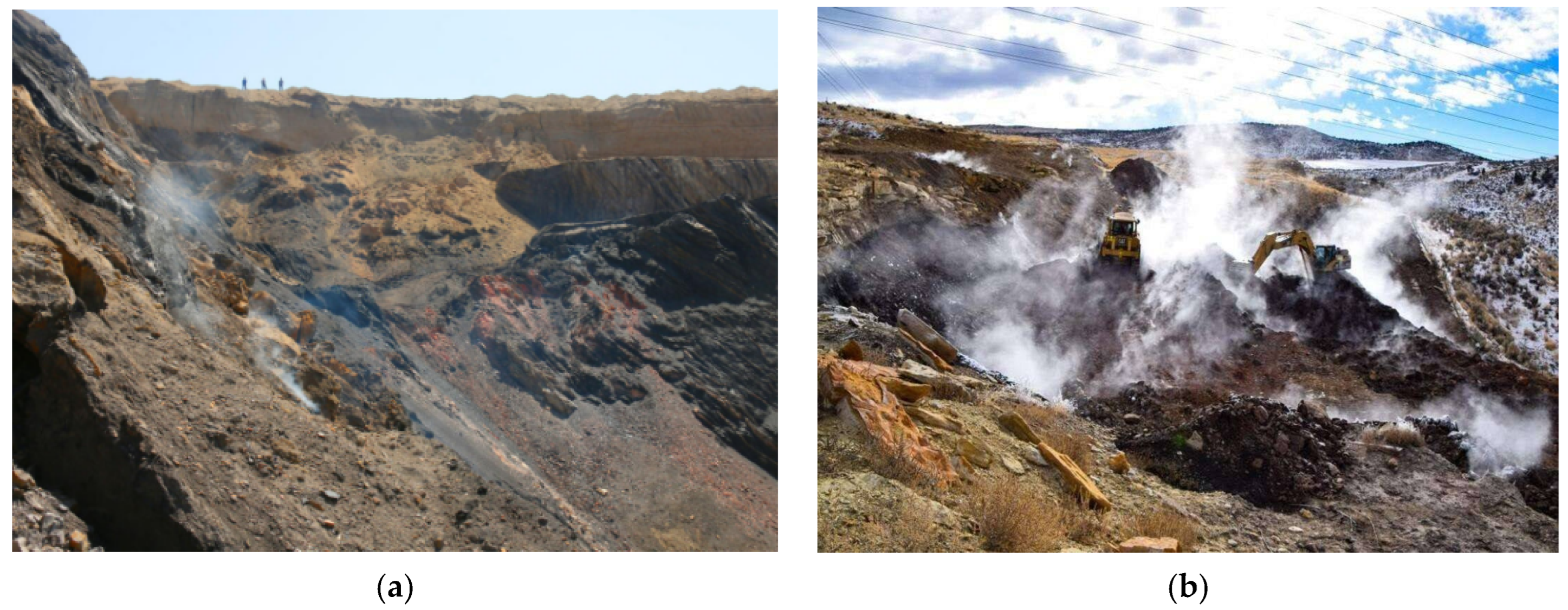
2.1. Engineering Background

The Xinjiang region is located in the heart of the Eurasian continent and is characterized by intense geological activity. Coal seams in this region are primarily steeply dipping because the region has experienced many crustal movements and climate changes in its history. Notably, steeply dipping coal seams in the Urumqi mining area alone account for over one-quarter of China’s total reserves of such coal seams [11,12]. Consequently, the region has abundant coal outcrops and, influenced by the temperate continental climate, the exposed coal seams are highly susceptible to spontaneous combustion. Xinjiang is one of the regions’ most severely affected by coalfield fires in China, and indeed globally [13]. As of the end of 2020, Xinjiang had 40 untreated fire areas, covering a total area of 4,777,300 m2 (as shown in Figure 1). Each year, such fires result in a loss of 4,561,600 tons of coal resources, bringing direct economic losses of approximately CNY 2 billion along with indirect environmental pollution, chiefly in the form of acid rain and greenhouse warming [14].
Considerable quantities of coal resources in Xinjiang are found at relatively shallow depths (average depth of <200 m). During the extraction of shallow coal seams, mining-induced fractures can easily penetrate the entire overburden, connecting the goaf with surface fire areas and enabling a rapid spread of fires into deeper coal seams. Meanwhile, the interaction between thermal stress caused by high temperatures and mining-induced stresses in the fire areas can damage the surrounding rock, as shown in Figure 1b. When this damage reaches a certain level, it results in a decrease in the strength of the overburden roof (coal body) [15]. When managing coal fires near a goaf, accidents caused by roof instability can easily occur. Therefore, researching management techniques for surface coal fires above shallow-buried goaf in steeply dipping coal seams in this region is vitally important to ensure safety in coal fire management and the green and sustainable development of the coal industry in China.
The No. 1 fire area in the Chatekale Fire Area (Xingliang II Mine Field) is located in Qiquanhu Town, Turpan City. According to a detailed survey report, the fire area is approximately 1135 m long from east to west and approximately 103 m wide from north to south, with a total area of 98,643 m2. The No. 1 fire area burns through the No. 2 and 3 coal seams, with a maximum temperature reaching 943 °C. The combustion depth ranges from 5 to 35 m, and the bottom boundary of combustion is at a depth of 855 m. The No. 2 and 3 coal seams are stable and well-developed throughout the area, gradually thickening from west to east. The seams dip to the north at an angle of 40°–42°. The thickness of the No. 2 coal seam ranges from 24.87 to 38.20 m, with an average of 28.53 m, while that of the No. 3 coal seam ranges from 7.53 to 20.28 m, with an average of 13.85 m.

2.2. Airborne Transient Electromagnetic Measurement

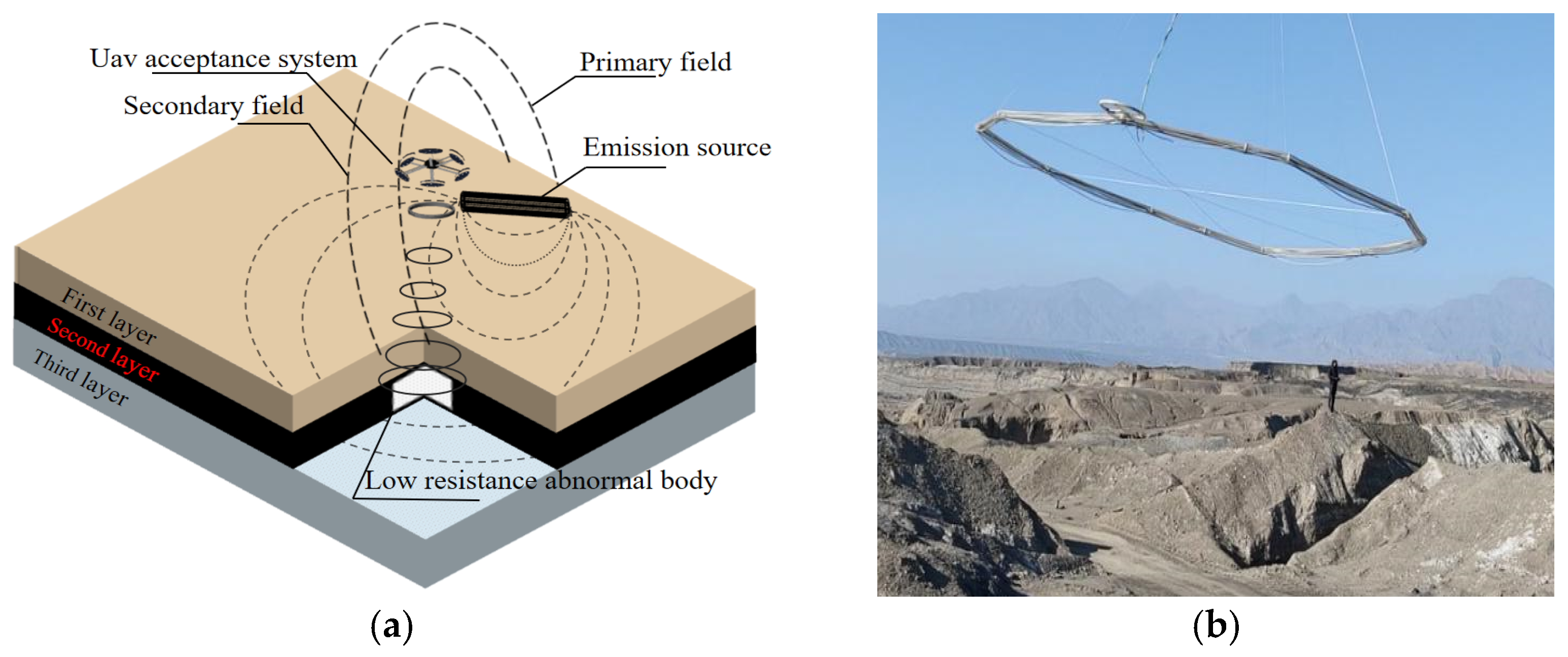
2.2.1. Exploration Principles

The coal seams in the fire-fighting area have experienced a long history of mining, resulting in numerous old kilns and goafs that are widely distributed. The main purpose of this exploration was to ascertain the spatial distribution characteristics and scale of goafs within the study region. This information then provided a modeling basis for evaluating the stability of goaf overburden under the influence of the temperature field in the fire area in numerical simulations, as well as theoretical and technical support for selecting subsequent management methods for the fire area.
The geophysical exploration area is affected by the collapse of goafs and construction activities for coal fire management; in addition, substantial topographical changes and gulleys hinder the precision of surface geophysical work. The topography of the study area is shown in Figure 2. The airborne transient electromagnetic method is characterized by its flexibility, high resolution, high efficiency, large coverage area, and strong adaptability to terrain [16,17]. Therefore, we employed this method to investigate a sub-area approximately 3800 m long from east to west and approximately 180 m wide from north to south within the fire area. The goal was to obtain information on the distribution of goafs within a depth range stretching 200 m below the surface in the exploration area.
When a cavity forms in a certain part of the underground rock strata, it disrupts the integrity and continuity of the original strata, resulting in a substantial electrical conductivity difference between the cavity and surrounding rock [18]. The airborne transient electromagnetic method is based on the differences in conductivity and magnetic susceptibility of rocks (minerals). It follows the principle of electromagnetic induction, utilizing airborne coils to emit electromagnetic wave pulses. On the basis of the secondary induced electromagnetic field signals received by receiving coils, it examines the electrical conductivity differences in the strata both horizontally and vertically and describes the electrical conductivity characteristics of the geoelectric section, ultimately detecting the characteristics of underground structures [19,20]. The exploration principle is illustrated in Figure 3. The principle is consistent with that of the ground transient electromagnetic method, with only the data acquisition method and inversion calculations being adjusted accordingly.
There is evidently a substantial electrical conductivity difference between water-bearing goafs and non-water-bearing goafs. Water-bearing goafs exhibit a low resistivity response, while non-water-bearing goafs show a relatively high resistivity response. Here, the geophysical exploration area is a collapsed fracture zone. According to preliminary design documents, the groundwater level above the goaf is +860 m, which lies in close proximity to the goaf and is accompanied by ground subsidence and fractures caused by coal mining. On the basis of currently available mining information, the goafs in this region are commonly water-bearing, and their electrical anomalies should present as low apparent resistivity anomalies against a high resistivity background (coal seams).

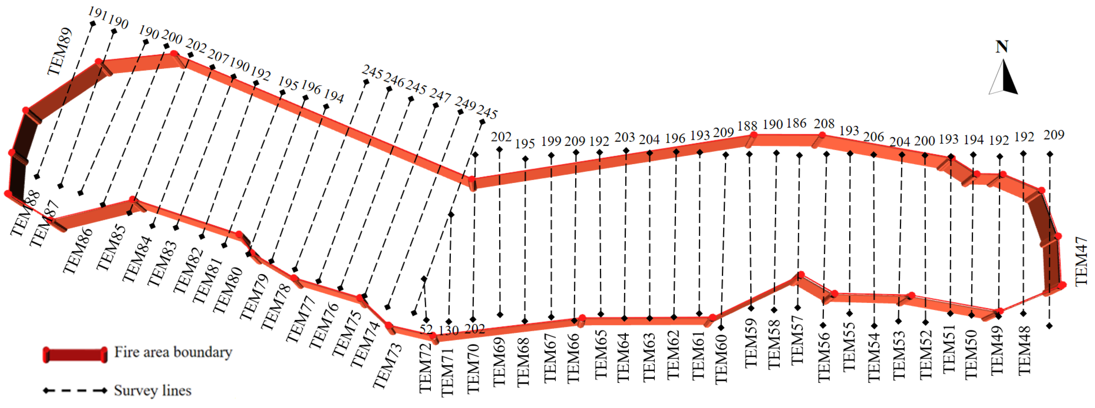
2.2.2. Layout of Geophysical Exploration Lines

As shown in Figure 4, the geophysical exploration measurement lines in the No. 1 fire area were arranged nearly vertically along the trend of the coal seams (the trend of the goaf). According to the Specification for Fire Extinguishing in Coal Fields, the spacing between measurement lines was set at 30 m, with measurement points spaced 3 m apart. The numbers in Figure 4 represent the lengths of the measurement lines. Following pre-construction tests, the construction parameters used in this study were as follows: the height of the coils above the ground was controlled to be approximately 5 m; the diameter of the transmitting coil was 5 m; the diameter of the receiving coil was 0.5 m; and the flying speed was 8 m/s. A total of 43 transient electromagnetic measurement lines were arranged in the No. 1 fire area, numbered TEM47-TEM89.

2.3. Numerical Simulation

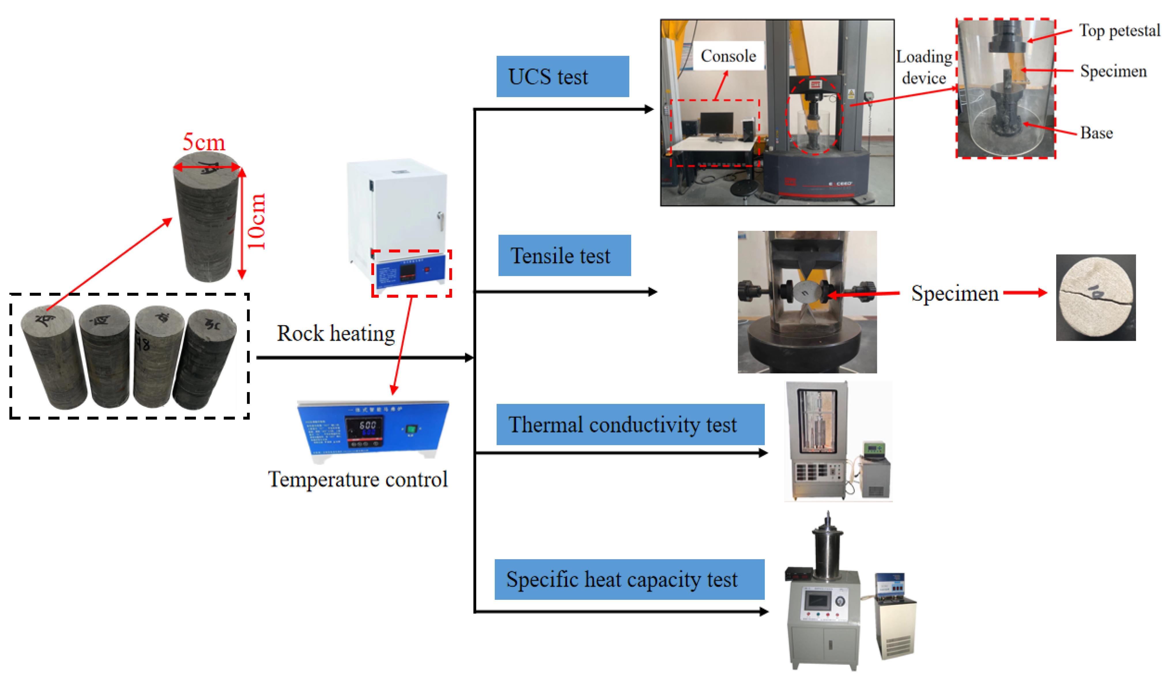
2.3.1. Properties of Overlying Rocks

Table 1 presents the basic mechanical parameters of rocks at room temperature. The high temperature of 943 °C in the fire area will cause thermal expansion of the rocks, leading to thermal stress. More importantly, the physical properties of the rocks will change with variations in temperature [21,22]. Therefore, to more accurately reflect the actual conditions on site, the model not only simulates the effects of thermal stress caused by the temperature field but also considers the range of high-temperature effects on the raw coal and overburden, as well as the variations in their mechanical properties.
For three typical rock samples—medium sandstone, fine sandstone, and siltstone—tests were conducted to measure their basic physical and mechanical parameters, including specific heat capacity, thermal conductivity, tensile strength, and elastic modulus at different temperatures. The experimental process is shown in Figure 5. In the UDEC calculation software (Version 7.0), the aforementioned material parameters were set as functions that varied with temperature.

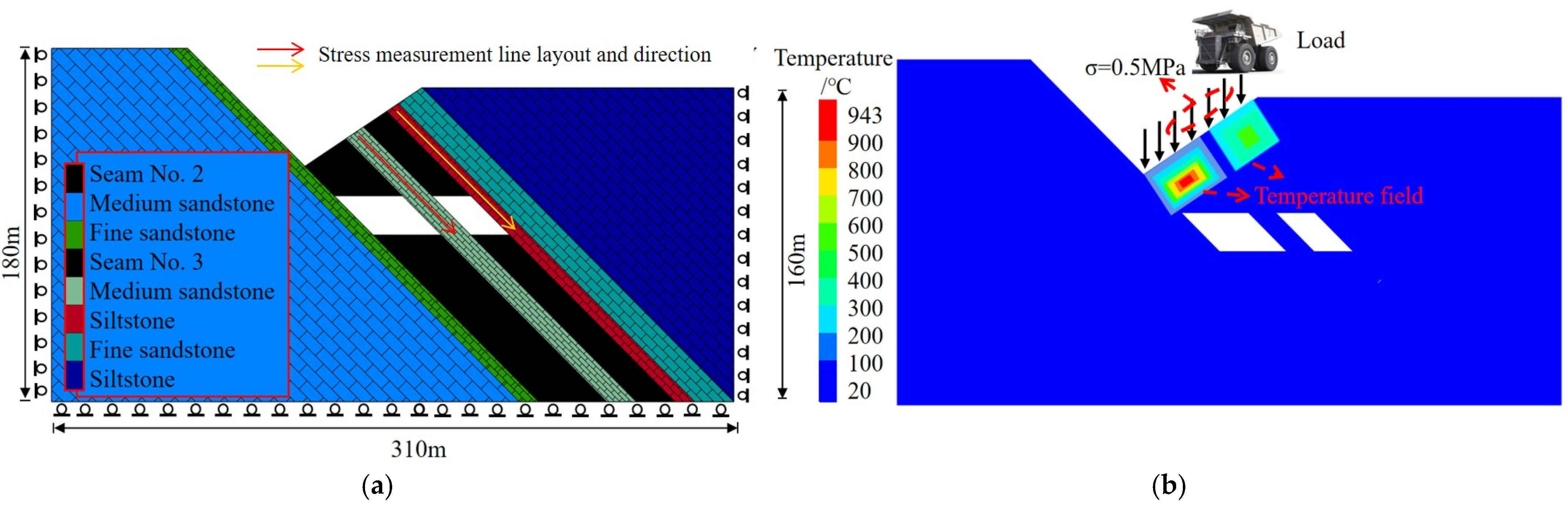
2.3.2. Numerical Calculation Model and Scheme

The block discrete element software UDEC features both mechanical analysis and thermal analysis modules, enabling thermo-solid coupling analysis of a research object. In UDEC, the thermal conduction process of the object follows Fourier’s law. For one-dimensional heat conduction, the magnitude of the heat flux can be calculated using the following equation [23]:
Q i = - λ i j T x j ,
where Qi is the heat flux in the i direction, in W/m2; λij is the thermal conductivity, in W/m°C; and T is the temperature, in °C. For a given object mass, the change in temperature can be expressed as follows:
T t = Q n e t c M ,
In UDEC, temperature changes will cause variations in the stress of the block. While temperature changes lead to variations in stress, the mechanical changes caused by thermal stress do not affect temperature changes. The change in elemental stress owing to temperature can be calculated using the following equation [24]:
Δ σ i j = δ i j 3 K α T Δ T ,
where Δσij is the stress change tensor; δij is the Kronecker delta, where δij = 1 when i = j and δij = 0 when i ≠ j; K* = K (plane strain) and K* = 6KG/(3K + 4G) (plane stress); K and G are the bulk modulus and shear modulus, respectively; αT is the coefficient of linear expansion; and ΔT is the change in temperature.
Combining the geological conditions of the No. 1 fire area in the Chatekale Fire Area and reasonably integrating and simplifying the strata conditions of the actual fire area in view of the actual geological background, a UDEC thermo-solid coupling numerical calculation model was established based on the locations of the goafs obtained from our geophysical results. This model was used to simulate stability changes in goaf overburden under three scenarios: without thermal coupling in the fire area, with thermal coupling in the fire area, and under the loading effects of large machinery during subsequent fire-fighting operations, providing guidance for the formulation of future fire-fighting plans. The basic numerical calculation model and a schematic diagram of the temperature field loading application are shown in Figure 6. The left, right, and lower boundaries of the model were fixed, with the rock strata modeled using the Coulomb slip model and the blocks modeled using the elastic model. In the model, on the basis of the temperature distribution results for the fire area at this section, measured using a DT-8869H high-temperature dual laser infrared thermometer, a temperature field was applied to simulate the effect of an area of fire above the goaf. The initial temperature of each rock stratum before coal combustion was set to 20 °C. Static loads simulating the effects of large machinery were applied, with the loading magnitude determined to be 0.5 MPa based on the actual weight of the machinery on site.

3. Results

3.1. Location and Dimensions of the Goaf

Through screening, filtering, and baseline correction of the raw data collected in No. 1 fire area in the Chatekale Fire Area (Xingliang II Mine Field), the exploration results were ultimately represented as contour maps of the apparent resistivity through various cross-sectional profiles, as shown in Figure 7. A total of 21 anomaly areas were detected. Our interpretation of the apparent resistivity contour maps was based on geophysical feature analysis, integrating the distribution of apparent resistivity contour anomalies, groundwater levels, minimum mining elevations, and the position of coal seam floors, among other factors, to provide a comprehensive interpretation. The area covered by the measurement lines was almost entirely comprised of goafs, and no anomalies were found in goafs outside the mining boundaries of +825 to +845 m. However, there were variations in the continuity of the overlying rock strata in the goafs, indicating differences in the degree of large-scale subsidence and fracture development. The exploration results for line TEM50 were verified through drilling, and the results were consistent, confirming the accuracy of the exploration results obtained using the airborne transient electromagnetic method.

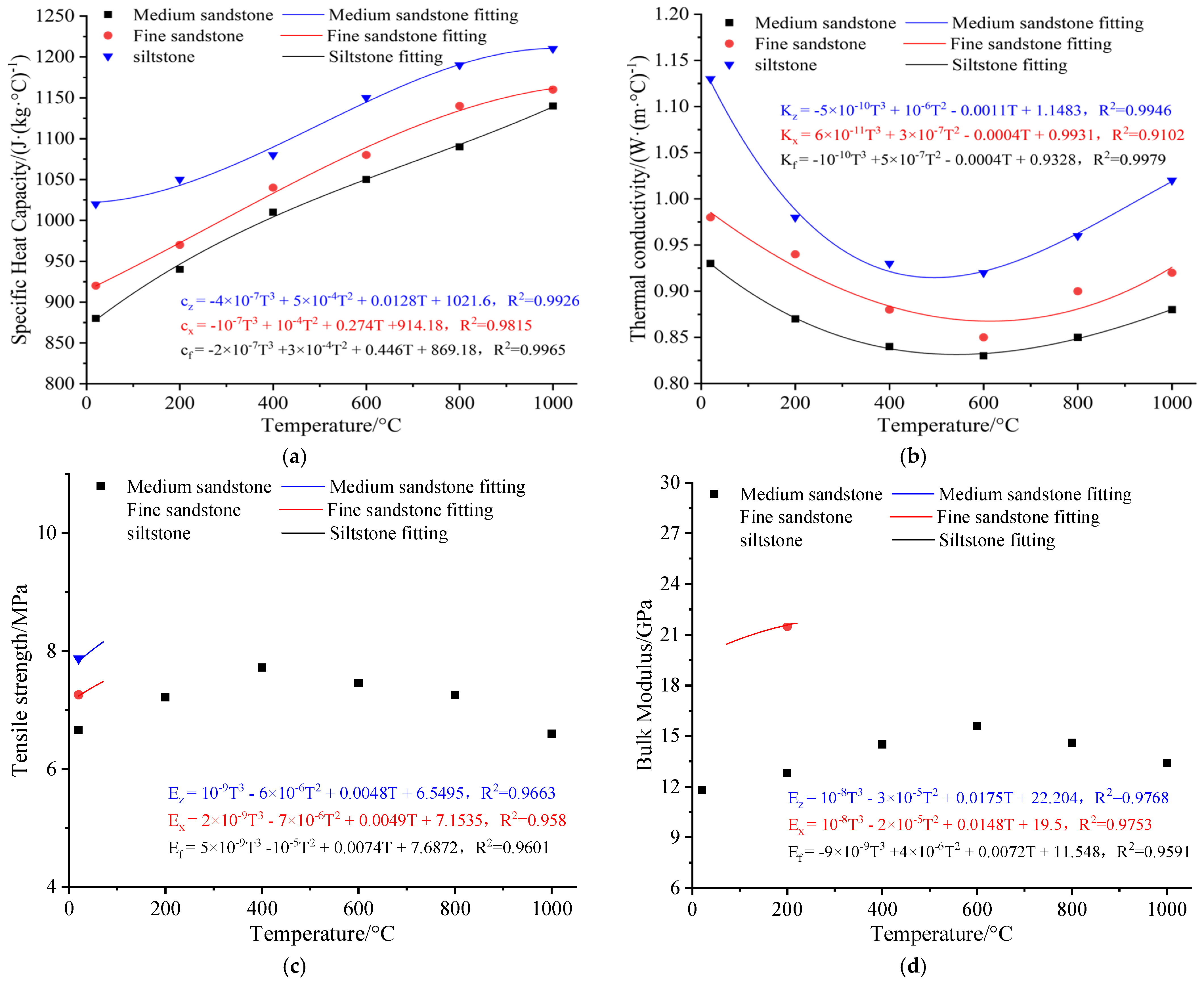
3.2. Thermophysical Properties of Overlying Rocks at Different Temperatures

The specific heat capacity was tested using a high-temperature calorimeter for solid materials, while the thermal conductivity was measured using a thermal conductivity meter. During the experiment, the samples were heated to predetermined temperatures (room temperature, 200, 400, 600, 800, and 1000 °C) using a muffle furnace, and the specific heat capacity and thermal conductivity of the rock samples were measured. The variations in specific heat capacity and thermal conductivity with changing temperature, as well as the fitting results for each rock type, are shown in Figure 8a,b. From these graphs, it can be observed that as the temperature increased, the thermal conductivity of medium sandstone, fine sandstone, and siltstone generally showed a trend of initially decreasing and then increasing, while the specific heat capacity exhibited an overall increasing trend. This mechanical behavior of sandstone at high temperatures has also been reported in previous studies.
To obtain the deformation parameters of rocks at high temperatures, uniaxial compression and tensile experiments were conducted. These experiments were carried out using a microcomputer-controlled electronic universal testing system (MTS) and a microcomputer-controlled triaxial electro-hydraulic servo universal testing machine (WAW-1000KN) (China Jinan Xinguang Testing Machine Manufacturing Co., Ltd., Jinan, China). The samples were heated to the predetermined temperatures in a muffle furnace and maintained at those temperatures for 20 min before conducting the corresponding tests. The experimental results were fitted, with the fitting results shown in Figure 8c,d. It can be observed that as the temperature increased, the tensile strength and bulk modulus of sandstone exhibited similar trends, initially increasing and then decreasing. Before 400 °C, the thermal expansion effect generated by high temperature makes the pores in the sandstone compressed and closed, and the sandstone becomes denser, so its tensile strength and elastic modulus show an increasing trend. However, after 400 °C, the excessive thermal expansion stress generated by high temperature causes new cracks among the crystalline particles in the sandstone, and the structural integrity of the sandstone decreases, so its tensile strength and elastic modulus gradually decrease with the continuous rise of temperature.

3.3. Stability Analysis of Overburden Above Goafs

From the above analysis, it can be seen that the mechanical properties of rock strata at the top of the goaf eventually decrease after the action of high temperature greater than 400 °C. Especially when the overlying rock in the goaf is thin, the coal fire burning for a long time will weaken the strength of the overlying rock in the whole thickness, which will seriously threaten the safety of the subsequent coal fire extinguishing engineering.

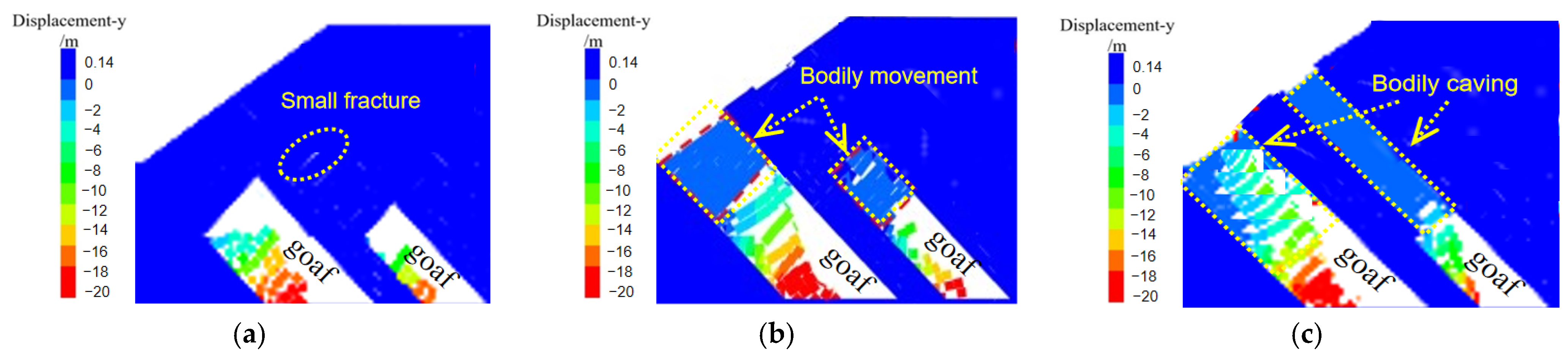
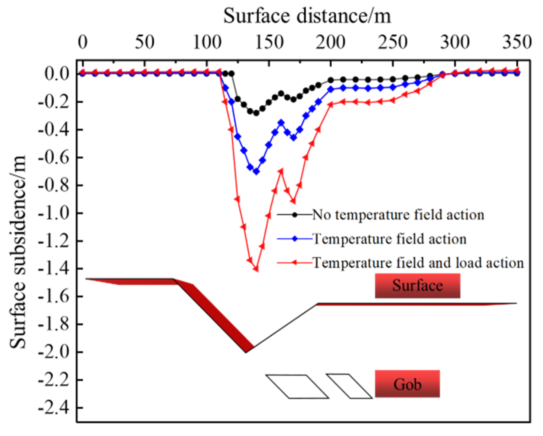
3.3.1. Analysis of Overburden Movement Law

The numerical simulation results were processed and analyzed, with Figure 9 illustrating the movement of rock strata in the fire area and surface subsidence under the three different simulation scenarios. From Figure 9, it can be seen that after coal mining, the stress in the coal body above the goaf was redistributed. When the tensile or shear stress on the coal body exceeded its ultimate strength, local failure occurred, causing blocks to fall into the goaf. In the absence of an applied temperature field, the coal body above the goaf remained structurally stable under the compression of the roof and floor rock strata, and the coal body did not slide into the goaf. Instead, blocks below the coal body fell into the goaf owing to their self-weight stress. After applying the temperature field, under the coupled effects of thermal stress and mining-induced stress, substantial displacement areas appeared in the coal body above the goaf, causing the overburden structure to tilt further into the goaf. Additional blocks of coal dropped, and some of these falling blocks formed overlaps owing to the compressive forces and friction between the rock strata, preventing further sliding of the coal body into the goaf. After applying the load, the amount of sliding of the coal body into the goaf further increased, with blocks at the interface between the coal body and rock layers dropping into the goaf. The compressive forces on the coal body from the roof and floor rock strata gradually decreased. Under the influence of these two adverse factors, friction between the rock strata decreased. When the frictional force is less than the external force, the overburden structure becomes unstable, leading to severe mining accidents.
The curve of vertical displacement at surface measurement points in the fire area as it varies with different working conditions is shown in Figure 10. It can be observed from this figure that the effects of the temperature field and the coupling of the temperature field with load did not influence the overall subsidence pattern of the surface, which consistently exhibited a “W” shape, where the maximum subsidence coincided with the central position of the goaf. However, the presence of the temperature field within the fire area and the coupling of this field with load markedly affected the displacement deformation of the surface. The existence of the fire area expanded the influence range of surface displacement above the goaf by approximately 10 m, with the maximum surface displacement increasing from 0.45 to 0.78 m. After the application of the load, the maximum surface displacement increased from 0.45 to 1.42 m, representing a displacement increase of up to 216%.

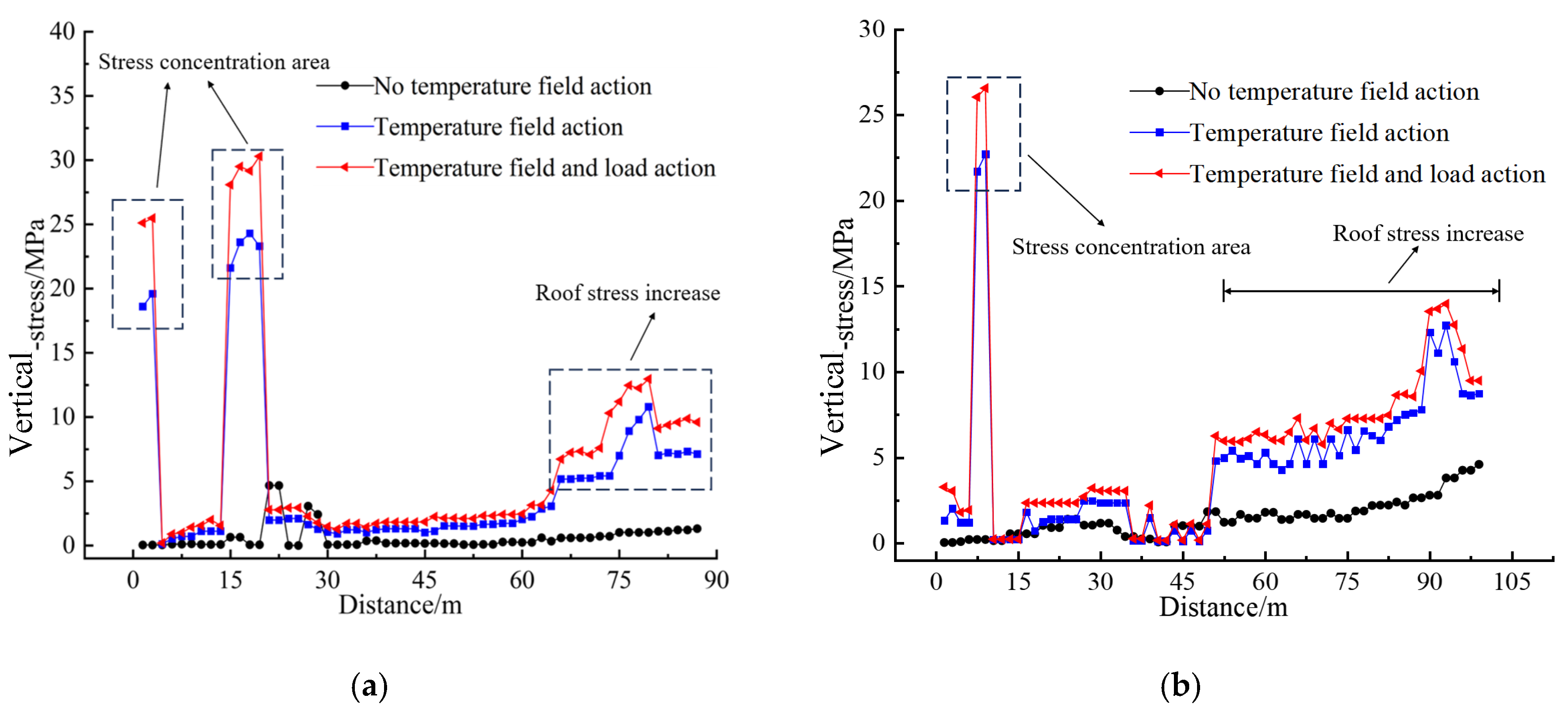
3.3.2. Analysis of Overburden Stress Evolution

The distribution of vertical stress under the three different simulated working conditions is shown in Figure 11. It can be observed that the maximum stress distribution pattern in the goaf was essentially the same across all three simulations. Influenced by coal strata mining, the goaf generated a secondary stress field in the upper and lower coal bodies as well as in the roof and floor rock strata. Substantial stress concentration occurred within a large range at the corners of the roof and floor of the goaf, with the stress concentration forming a stress arch above the coal body in the left-hand section of the goaf. This is a result of the steeply dipping, super-thick coal seam being located above, while the roof and floor are positioned on both sides. After coal is extracted, the vertical constraints are markedly reduced, and the mining process also causes the roof and floor rock strata to bend, break, and shift toward the goaf. This results in clamping on the coal body, ultimately leading to stress concentration.
The distribution of vertical stress in the roof of the goaf under the three different simulated working conditions is shown in Figure 12. It can be observed that the vertical stress variation patterns on both sides of the goaf roof were quite similar, with the stress variation curve exhibiting a concave shape, being higher on the sides and lower in the middle. Without the application of the temperature field, the maximum vertical principal stress on the left-hand side of the goaf roof was 4.7 MPa. Under the influence of the temperature field, the roof stress increased to 24.3 MPa, representing an increase of 417%. With the combined effects of the temperature field and load, the stress rose to 30.3 MPa, representing an increase of 544.7%. On the right-hand side of the goaf roof, without the temperature field applied, the maximum vertical principal stress was 4.6 MPa. Under the effect of the temperature field, the roof stress rose to 22.7 MPa, representing an increase of 393.5%. With both the temperature field and load applied, the stress reached 26.6 MPa, representing an increase of 478.3%.
In summary, the effect and presence of the temperature field in the fire area had a considerable impact on the stability of the overburden. This was primarily reflected in the increased displacement of the coal body above the goaf, greater concentration of stress in the coal body, and higher likelihood of key rock blocks in the coal body experiencing rotation, sliding, and tipping. The presence of the goaf fire area reduced the stability of the goaf. Therefore, in the future management of fire areas, it will be essential to conduct precise blasting treatments of the goaf in advance to ensure the safety of subsequent remediation projects.

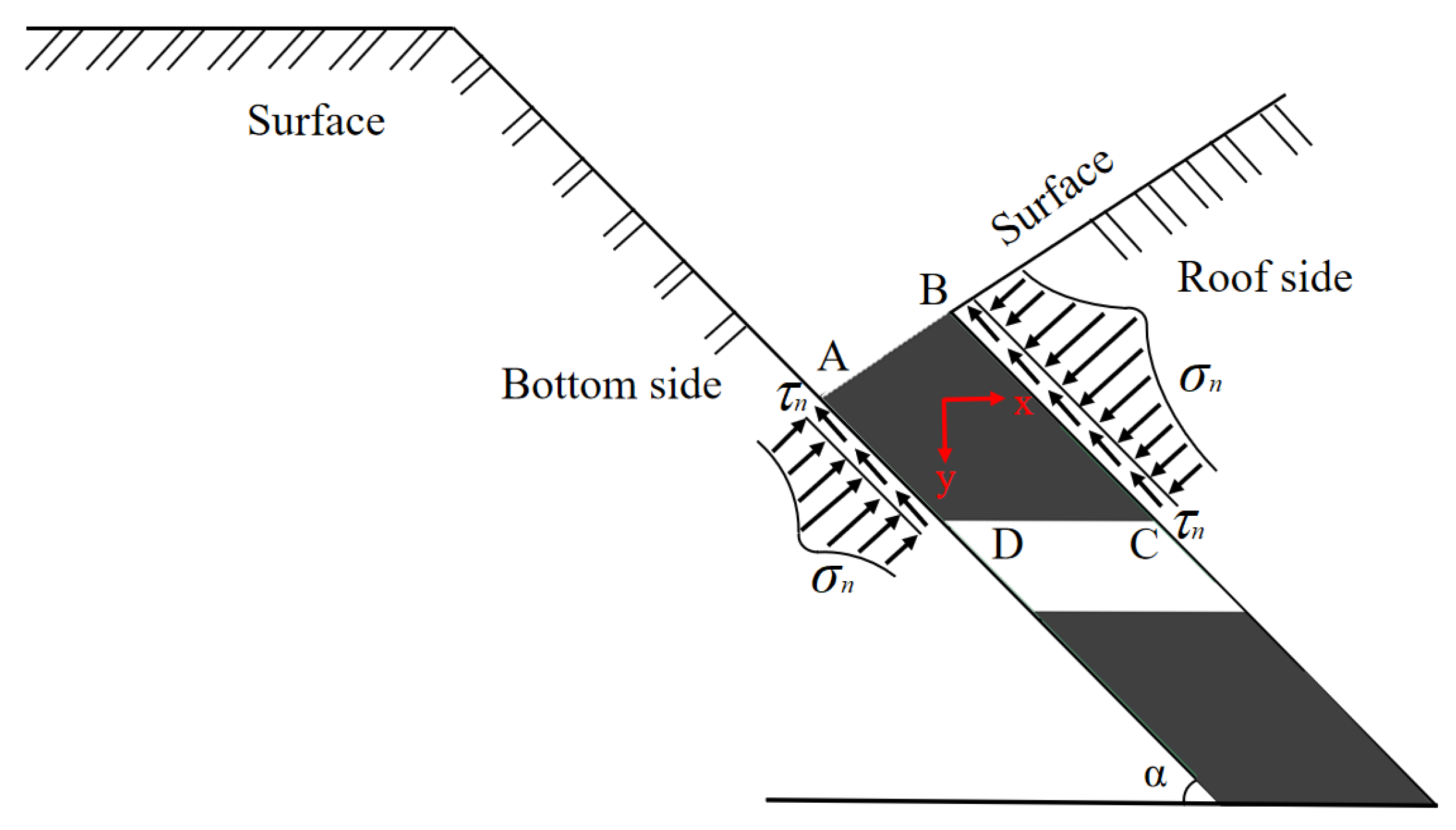
3.3.3. Analysis of Overburden Mechanical Structure

Under normal circumstances, after coal mining, the stress in the surrounding rock changes owing to mining-induced effects, leading to alterations in the stress state of the overburden above the goaf. An imbalance in the stress on the coal body above a near-surface goaf is sufficient to create goaf instability. To explore the static load stress distribution characteristics of coal bodies above goafs in inclined coal seams, a mechanical model was established, as shown in Figure 13. Under triaxial stress conditions, steeply dipping coal seams primarily experience normal stress (σn) and shear stress (τn) at the contact surface owing to the forces from the roof and floor. The normal stress at the contact surface mainly arises from the clamping force exerted by the roof and floor on the coal body. Assuming the length of the goaf is one unit, the calculation formula for the stress relationship on the coal body (A, B, C, D in Figure 13) above the goaf is as follows:
Q = G sin α - τ n ( L 1 + L 2 ) ,
where α is the angle of inclination of the coal seam, in degrees (°); Q is the force exerted in the dip direction of the overburden media above the goaf per unit length, in N/m; G is the gravitational force on the coal body above the goaf per unit length, in N/m; and L1 and L2 are the lengths of the coal body on the floor side (AD) and roof side (BC), respectively, in m.
The shear stress acting on the coal body above the goaf is given by:
τ n = σ n tan θ + C ,
where θ is the angle of internal friction, in degrees (°); and C is the cohesion, in Pa.
The final dip stress relationship of the coal body above the goaf is given by:
Q = G sin α - σ n tan θ ( L 1 + L 2 ) C ( L 1 + L 2 )
When Q > 0 in Equation (6), the coal body ABCD slides into the goaf; when Q ≤ 0, the coal body ABCD is in a stable state. Considering the effects of thermal stress from the combustion zone in the fire area and the loads from large machinery during subsequent construction operations, there is a distinct possibility of instability in the overburden above the goaf, leading to safety issues during construction. Therefore, further numerical simulation analysis is required for validation.

4. Field Application

Our findings detailed above indicate that the presence of a temperature field in the fire area markedly reduces the stability of the overburden above the goaf, resulting in a high risk of accidents during subsequent construction using large machinery. Therefore, in line with the principle of ensuring the safety of future underground mining operations, targeted management measures are proposed for 21 goafs discovered by the airborne transient electromagnetic method in the No. 1 fire area. These measures include:
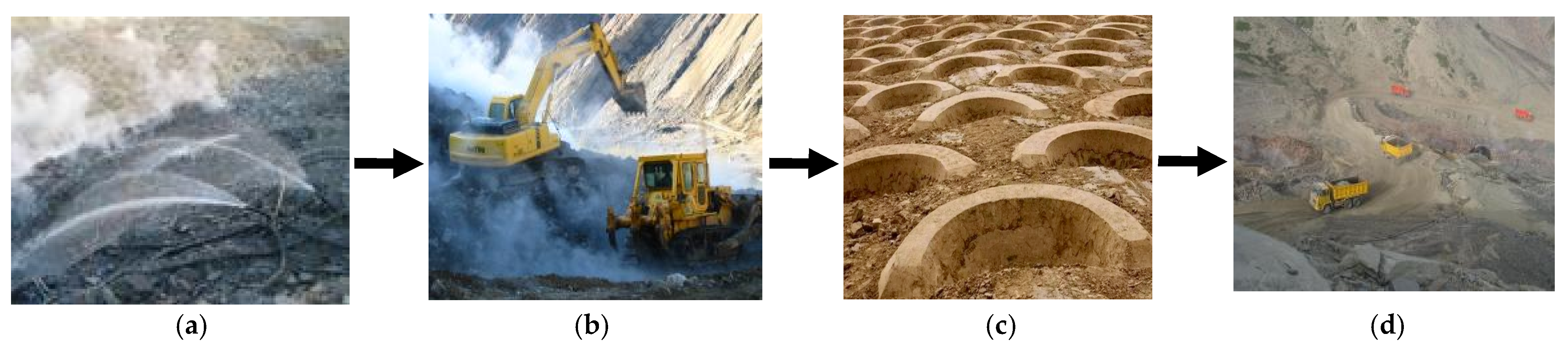
  • Injecting water into the surface high-temperature zones of the fire area to extinguish surface flames and reduce ground temperatures, thereby establishing a foundation for mechanical operations to be conducted within a safe temperature range.
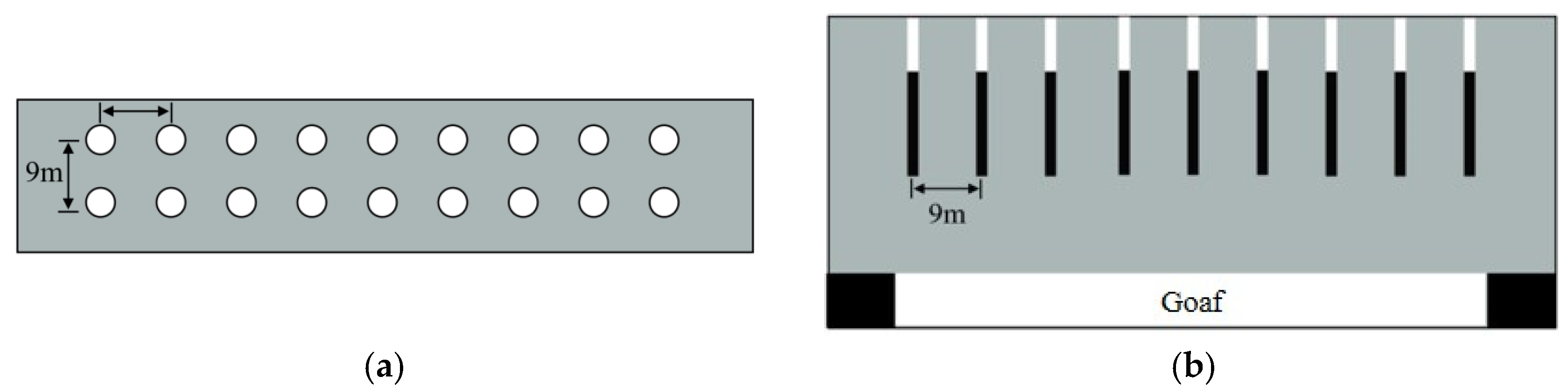
  • Conducting management of the goaf based on its exploration results by arranging boreholes for blasting. Vibration management should be applied to shallow goafs to ensure the complete collapse of the goaf tunnels in one go, eliminating safety hazards for machinery and ensuring the safety of stripping operations. Figure 14 shows the layout of the goaf management plan, with boreholes arranged vertically to the ground and spaced 9 m apart to mitigate the adverse effects of blasting on tunnel stability. The explosive used is a mining-grade water gel explosive, with a detonation velocity of 3600 m/s and a power factor of 239 mL. The blasting hole depth is 30 m, the blasting hole diameter is 75 mm, the Charging diameter is 63 mm, the Charging length is 13 mm and the sealing length is 17 m.
  • Combining bulldozers, excavators, and shallow-hole blasting drills to carry out surface stripping and leveling work in the fire area. This involves filling-in collapse pits, cracks, and shallow goafs to create a working face, thereby establishing a suitable construction site for subsequent operations such as soil covering.
  • Implementing water injection in fish-scale-like pits on the surface of the fire area to reduce the temperature of the deep fire source to the levels required by the Specification for Fire Extinguishing in Coalfields.
  • Conducting compaction of the stripped surface to ensure the closure of gaps between the goaf and the surface.
  • Covering the leveled management area with loess and performing a second compaction using machinery.
After these management measures, the surface combustion characteristics within the fire area were shown to have disappeared, and the temperature in the fire area dropped from pre-management levels of 500–600 °C to below 100 °C. The monitoring of boreholes indicated a rapid decrease in temperature, effectively controlling and extinguishing the fire area. The flowchart of the on-site management process in the fire area is shown in Figure 15.

5. Discussion

  • The estimated budget of the fire extinguishing project in the Chatekale Fire Area (Xingliang II Mine Field) is CNY 95.4595 million. The implementation of the fire extinguishing project will protect 37.62 million tons of coal resources from the threat of coal field fires, reduce the coal burning loss by 254.23 million tons per year, and reduce the annual economic loss by CNY 50.85 million based on the coal price of 200 CNY/t. After thorough treatment, the loss of CNY 7.524 billion can be directly reduced, and the economic benefits are remarkable.
  • The Chatekale Fire Area (Xingliang II Mine Field) annually emits 661,060 tons of CO2, 2491 tons of hydrocarbons, 1881 tons of nitrogen oxides, and 2162 tons of SO2 due to combustion. Additionally, it releases a large amount of harmful elements such as fluorine and arsenic. After the completion of the fire area project, the large amounts of toxic and harmful gases produced by the combustion of coal seams in the fire area will be eliminated, effectively improving the local air quality and the ecological environment of the surrounding atmosphere, water bodies, and soil.
  • After the fire extinguishing project is completed, the subsidence and fissures on the surface of the fire area will be stripped, leveled, and filled, which will transform the topography of the fire area, reduce the occurrence of geological disasters around the fire area, reduce soil desertification and soil erosion, and improve the local ecological environment, with significant ecological benefits.

6. Conclusions

  • The use of the airborne transient electromagnetic method enabled precise exploration of the goaf beneath the No. 1 sub-fire area in the Chatekale Fire Area (Xinjiang II Mine Field). The exploration results indicated no goaf beyond the mining boundary of +825 to +845 m, aligning with drilling verification results. This demonstrates the superiority of the airborne transient electromagnetic method in exploring goafs.
  • The presence of the temperature field markedly affects the stability of the overburden above the goaf, primarily manifested in the increased displacement of the coal body above the goaf, greater concentration of stress in the coal body, and higher likelihood of key rock blocks in the coal body experiencing rotation, sliding, and tipping. After the application of the temperature field, the maximum surface displacement increased from 0.45 to 0.78 m. Following the application of load, the maximum surface displacement rose from 0.45 to 1.42 m, representing an increase of up to 216%. Additionally, after applying the temperature field, the peak vertical stress in the goaf increased from 8.5 to 32 MPa, and after loading, the peak stress rose to 36 MPa.
  • In the subsequent management of near-surface goaf fire areas, a strategy has been proposed that involves first conducting precise blasting treatments in the goaf, followed by comprehensive fire-fighting measures. Monitoring results indicate successful management of the fire area.

Author Contributions

Conceptualization, P.Z. and G.Z.; methodology, Z.Z.; software, X.L.; validation, H.L., D.Y., and W.J.; formal analysis, P.Z.; investigation, R.C. and G.Z.; resources, Z.Z.; data curation, X.L.; writing—original draft preparation, Z.Z.; writing—review and editing, P.Z.; visualization, G.Z.; supervision, Z.Z.; project administration, X.L.; funding acquisition, P.Z. All authors have read and agreed to the published version of the manuscript.

Funding

This research was funded by Autonomous region key research and development plan project, grant number 2023B03011-2 and 2023B01009-1.

Institutional Review Board Statement

Not applicable.

Informed Consent Statement

Not applicable.

Data Availability Statement

The original contributions presented in this study are included in the article. Further inquiries can be directed to the corresponding author.

Acknowledgments

We thank David Wacey for editing the English text of a draft of this manuscript.

Conflicts of Interest

Authors Pihong Zhang and Guoqing Zhu were employed by the company Xinjiang Baodi Mining Co., Ltd.; author Wei Jiang was employed by the company Xinjiang Yaxin Coal Bed Gas 156 Exploration Co., Ltd. The remaining authors declare that the research was conducted in the absence of any commercial or financial relationships that could be construed as a potential conflict of interest.

Correction Statement

This article has been republished with a minor correction to the contact information of Mr. Wei Jiang. This change does not affect the scientific content of the article.

References

  1. Guo, J.; Gao, B.; Liu, Y.; Chen, C.; Cai, G.; Wang, L. Research and Application of CO2 Fire Prevention Mechanism and Key Technologies in Mines: A Review. Fire 2024, 7, 353. [Google Scholar] [CrossRef]
  2. Szurgacz, D.; Tutak, M.; Brodny, J.; Sobik, L.; Zhironkina, O. The method of combating coal spontaneous combustion hazard in goafs—A case study. Energies 2020, 12, 4538. [Google Scholar] [CrossRef]
  3. Mohalik, N.K.; Singh, R.V.K.; Pandey, J.; Singh, V.K. Application of nitrogen as preventive and controlling subsurface fire—Indian context. J. Sci. Ind. Res. India 2005, 64, 273–280. [Google Scholar]
  4. Bajestani, M.S.; Nasir, O.; Coulson, C. Analysis of Long-Term Thermo–Hydro–Mechanical Behavior in the Near-Field of a Deep Geological Repository System. Minerals 2024, 14, 1262. [Google Scholar] [CrossRef]
  5. Shao, H.; Radeisen, E.; Hesser, J.; Wang, W.; Kolditz, O. Coupled Processes at Micro- and Macroscopic Levels for Long-Term Performance Assessment Studies of Nuclear Waste Repositories. Minerals 2024, 14, 453. [Google Scholar] [CrossRef]
  6. Shang, X.; Zhang, Z.; Xu, X.; Liu, T.; Xing, Y. Mineral Composition, Pore Structure, and Mechanical Characteristics of Pyroxene Granite Exposed to Heat Treatments. Minerals 2019, 9, 553. [Google Scholar] [CrossRef]
  7. Yang, Y.L.; Zheng, K.Y.; Li, Z.W.; Li, Z.H.; Si, L.L.; Hou, S.S.; Duan, Y.J. Experimental study on pore-fracture evolution law in the thermal damage process of coal. Int. J. Rock Mech. Min. Sci. 2019, 116, 13–24. [Google Scholar] [CrossRef]
  8. Zhang, W.Q.; Sun, Q.; Zhu, S.Y.; Wang, B. Experimental study on mechanical and porous characteristics of limestone affected by high temperature. Appl. Therm. Eng. 2017, 110, 356–362. [Google Scholar] [CrossRef]
  9. Liu, P.; Cui, S.G.; Li, Z.H.; Xu, X.F.; Guo, C. Influence of surrounding rock temperature on mechanical property and pore structure of concrete for shotcrete use in a hot-dry environment of high-temperature geothermal tunnel. Constr. Build. Mater. 2019, 207, 329–337. [Google Scholar] [CrossRef]
  10. Sun, Q.; Zhang, W.Q.; Su, T.M.; Zhu, S.Y. Variation of wave velocity and porosity of sandstone after high temperature heating. Acta Geophys. 2016, 64, 633–648. [Google Scholar] [CrossRef]
  11. Pan, C.; Xia, B.; Zuo, Y.; Yu, B.; Ou, C. Mechanism and control technology of strong ground pressure behaviour induced by high–position hard roofs in extra–thick coal seam mining. Int. J. Min. Sci. Technol. 2022, 32, 499–511. [Google Scholar] [CrossRef]
  12. Xu, J.; Zhu, W.; Xu, J.; Wu, J.; Li, Y. High–intensity longwall mining-induced ground subsidence in Shendong coalfield, China. Int. J. Rock Mech. Min. Sci. 2021, 141, 104730. [Google Scholar] [CrossRef]
  13. Zhang, B.; Xiao, F.; Jin, W. Burnt coal field detection via magnetic exploration. Environ. Earth Sci. 2023, 82, 160. [Google Scholar] [CrossRef]
  14. Wang, Y.; Wang, W.; Wang, W.; Duan, P.; He, X.; Lu, Q. Distribution, Occurrence and Enrichment Causes of Sodium in Middle Jurassic Coal from Zhundong Coalfield, Xinjiang. Minerals 2024, 14, 146. [Google Scholar] [CrossRef]
  15. Saadat, M.; Khishvand, M.; Seccombe, A. FLAC3D Simulation of Caving Mechanism and Strata Fracture Response in Underground Mining. Mining 2024, 4, 818–840. [Google Scholar] [CrossRef]
  16. Karanam, V.; Motagh, M.; Garg, S.; Jain, K. Multi-sensor remote sensing analysis of coal fire induced land subsidence in Jharia Coalfields, Jharkhand, India. Int. J. Appl. Earth Obs. Geoinf. 2021, 102, 102439. [Google Scholar] [CrossRef]
  17. Moros, J.; Gaona, I.; Laserna, J.J. Remotely Exploring Deeper-Into-Matter by Non-Contact Detection of Audible Transients Excited by Laser Radiation. Sensors 2017, 17, 2960. [Google Scholar] [CrossRef] [PubMed]
  18. Massone, Q.; Druon, S.; Triboulet, J. A Novel 3D Reconstruction Sensor Using a Diving Lamp and a Camera for Underwater Cave Exploration. Sensors 2024, 24, 4024. [Google Scholar] [CrossRef]
  19. Anghelescu, L.; Diaconu, B.M. Advances in Detection and Monitoring of Coal Spontaneous Combustion: Techniques, Challenges, and Future Directions. Fire 2024, 7, 354. [Google Scholar] [CrossRef]
  20. Syed, T.H.; Riyas, M.J.; Kuenzer, C. Remote sensing of coal fires in India: A review. Earth-Sci. Rev. 2018, 187, 338–355. [Google Scholar] [CrossRef]
  21. Shevtsova, A.; Stanchits, S.; Filev, E.; Karamov, T.; Stukachev, V.; Spasennykh, M. Assessment of Saturation Effect on Hydraulic Fracturing in Sandstone and Thermally Treated Granite. Minerals 2023, 13, 777. [Google Scholar] [CrossRef]
  22. Sanchez-Barra, A.; Zambrano-Narvaez, G.; Chalaturnyk, R. An In-Depth Analysis of Strength and Stiffness Variability in 3D-Printed Sandstones: Implications for Geomechanics. Energies 2023, 16, 5406. [Google Scholar] [CrossRef]
  23. Jendryś, M.; Hadam, A.; Ćwiękała, M. Directional Hydraulic Fracturing (DHF) of the Roof, as an Element of Rock Burst Prevention in the Light of Underground Observations and Numerical Modelling. Energies 2021, 14, 562. [Google Scholar] [CrossRef]
  24. Rajwa, S.; Janoszek, T.; Świątek, J.; Walentek, A.; Bałaga, D. Numerical Simulation of the Impact of Unmined Longwall Panel on the Working Stability of a Longwall Using UDEC 2D—A Case Study. Energies 2022, 15, 1803. [Google Scholar] [CrossRef]
Figure 1. Distribution of coalfield fires in Xinjiang region of China (a); structural profile shallow-buried goaf (b).
Fire 08 00033 g001
Figure 2. Topography of the prospecting area. (a) Topography; (b) Construction situation.
Fire 08 00033 g002
Figure 3. Schematic diagram of the airborne transient electromagnetic measurement. (a) Principle for goaf exploration; (b) Field work drawing.
Fire 08 00033 g003
Figure 4. Airborne transient electromagnetic measurement line layout.
Fire 08 00033 g004
Figure 5. Rock mechanics experimental process of overlying strata.
Fire 08 00033 g005
Figure 6. Schematic numerical model diagrams. (a) Basic numerical model; (b) Pressure and temperature loading.
Fire 08 00033 g006
Figure 7. Abnormal area apparent resistivity contour maps.
Fire 08 00033 g007
Figure 8. Experimental results of thermal properties: (a) Specific heat capacity; (b) Thermal conductivity; (c) Tensile strength; (d) Elastic modulus.
Fire 08 00033 g008
Figure 9. Rock strata movement in a fire area. (a) Without the effect of the temperature field; (b) With the effect of the temperature field; (c) With the effect of stress and temperature field.
Fire 08 00033 g009
Figure 10. Subsidence curves of overlying strata.
Fire 08 00033 g010
Figure 11. Vertical stress distribution cloud maps. (a) Without the effect of the temperature field; (b) With the effect of the temperature field; (c) Temperature field-load interaction.
Fire 08 00033 g011
Figure 12. Vertical stress distribution of goaf roof. (a) Left goaf roof; (b) Right goaf roof.
Fire 08 00033 g012
Figure 13. Diagram of stability evaluation of the rock overlying a goaf (A, B, C, D are the four inflection points of the shape of goaf roof strata).
Fire 08 00033 g013
Figure 14. Borehole layout. (a) Planar profile; (b) Dip profile.
Fire 08 00033 g014
Figure 15. Site construction management flow chart. (a) Injecting water into the surface of the fire area; (b) Stripping and leveling; (c) Water injection in fish-scale-like pits; (d) Transporting soil for compaction.
Fire 08 00033 g015
Table 1. Initial mechanical parameters of the rock strata used in the simulation.
StratumDensity
/Kg/m3
Elastic Modulus
/GPa
Shear Modulus
/GPa
Angle of Internal
friction/°
Cohesion
/MPa
Tensile Strength
/MPa
Siltstone270022.618.4368.27.8
Fine sandstone260019.816.3357.37.2
Medium sandstone245011.68.5366.86.6
Coal14704.53.4331.91.7
Disclaimer/Publisher’s Note: The statements, opinions and data contained in all publications are solely those of the individual author(s) and contributor(s) and not of MDPI and/or the editor(s). MDPI and/or the editor(s) disclaim responsibility for any injury to people or property resulting from any ideas, methods, instructions or products referred to in the content.

