Article

Nonlinear Analysis of a Steel Frame Structure Exposed to Post-Earthquake Fire

by
Alaa T. Alisawi
*,
Philip E. F. Collins
and
Katherine A. Cashell
Department of Civil and Environmental Engineering, Brunel University London, London UB8 3PN, UK
*
Author to whom correspondence should be addressed.
Submission received: 2 September 2021 / Revised: 4 October 2021 / Accepted: 6 October 2021 / Published: 15 October 2021
(This article belongs to the Special Issue Performance-Based Design in Structural Fire Engineering)

Abstract

:
The probability of extreme events such as an earthquake, fire or blast occurring during the lifetime of a structure is relatively low but these events can cause serious damage to the structure as well as to human life. Due to the significant consequences for occupant and structural safety, an accurate analysis of the response of structures exposed to these events is required for their design. Some extreme events may occur as a consequence of another hazard, for example, a fire may occur due to the failure of the electrical system of a structure following an earthquake. In such circumstances, the structure is subjected to a multi-hazard loading scenario. A post-earthquake fire (PEF) is one of the major multi-hazard events that is reasonably likely to occur but has been the subject of relatively little research in the available literature. In most international design codes, structures exposed to multi-hazards scenarios such as earthquakes, which are then followed by fires are only analysed and designed for as separate events, even though structures subjected to an earthquake may experience partial damage resulting in a more severe response to a subsequent fire. Most available analysis procedures and design codes do not address the association of the two hazards. Thus, the design of structures based on existing standards may contribute to a significant risk of structural failure. Indeed, a suitable method of analysis is required to investigate the behaviour of structures when exposed to sequential hazards. In this paper, a multi-hazard analysis approach is developed, which considers the damage caused to structures during and after an earthquake through a subsequent thermal analysis. A methodology is developed and employed to study the nonlinear behaviour of a steel framed structure under post-earthquake fire conditions. A three-dimensional nonlinear finite element model of an unprotected steel frame is developed and outlined.

1. Introduction

Extreme events such as earthquakes, fires or blasts have a low likelihood of incidence during a structure’s lifecycle but they can have tremendous after-effects with regard to the safety of any inhabitants and the integrity of the structure. In addition, there may be a higher risk of a second extreme event occurring, owing to any damage that occurs during the initial event, for example, a fire after an earthquake [1,2]. In such a case, the structure is exposed to multiple hazards. The current paper is concerned with the response of steel framed structures when subjected to an earthquake that is followed by a fire. This particular multi-hazard event is known as a post-earthquake fire (PEF). Most structures are required to satisfy ‘life safety’ design criteria as specified in design standards. These codes guarantee that structures remain stable and continue to carry gravity loads, dead loads and a percentage of live loads during extreme events, thus allowing the building’s occupants to evacuate the buildings safely [3,4]. Based on the function of the structure and its importance, the allowable rate and type of damage that is tolerable during an extreme loading is typically specified during its design. The design codes ensure building safety under a variety of load combinations that represent different extreme loading scenarios. However, the load combination of an earthquake followed by a fire has yet to be included in international design standards although the forces and moments applied to a structure during a PEF are likely to be much greater than for individual extreme events [4,5].
Mitigating the effects of PEF on buildings during the design process in order to ensure the safety of occupants and emergency service personnel is a crucial aspect to consider for any PEF safety strategy. The effects of a PEF can be diminished by controlling and determining the status of structural stresses after the first event (the earthquake) and also designing and/or strengthening the building to withstand and survive the fire loading. Eurocode 8 Part 1 [6] provides a design load combination for a set of different actions (Equation (1)). These actions must be combined with those from other loads, such as permanent loads (G), pre-stressing loads (P), seismic actions ( A E , d ) and a proportion of the variable (live) loads (Q). A specific reduction factor ( Ψ 2 , i   ) is provided in Eurocode 8 and the recommended values of factors for buildings are specified in Eurocode 3 Part 1–2 [7].
f 1 G k , j + P + A E , d + i 1 Ψ 2 , i     Q k , i
There are two important concepts that should be considered when designing a structure that can resist different magnitudes of earthquakes, which are frequent earthquakes and design earthquakes. The return period of a frequent earthquake is lower than that of a design or ‘maximum considered’ earthquake. A design earthquake is characterized by a return period R of 475 years, which corresponds to a 10% probability of exceedance in 50 years. As shown in Figure 1, a usual building must be operational for a frequent return period, and safe in the zone of a design earthquake. For very important structures, the critical components must remain operational for a ‘maximum considered’ earthquake [8,9].
In this context, it is clear that in order to develop appropriate design methods for a PEF event, it is critical to first develop a good understanding of the complex structural behaviour that occurs in this scenario. The structural behaviour and material properties of the remaining parts of the structure after the first hazard are classified as the input properties of the structure during the fire, and it is important that these are accurately represented. For this reason, in the current paper, a multi-hazard analysis approach is presented for steel-framed buildings. The paper proceeds with an overview of the state-of-the-art, which is followed by a description of the three-dimensional (3D) finite element (FE) model that was developed using the Abaqus software [10]. The damage caused to a structure during and after an earthquake is included in the sequential thermal analysis. This methodology is developed and employed to study the nonlinear behaviour of a steel-framed structure when subjected to the PEF loading condition.

2. State of the Art

There has been limited research into multi-hazard extreme events and their effects on building structures compared with single extreme events such as a fire or an earthquake. Nevertheless, as more has become known and understood about single hazard events, researchers have begun to study the more complex case of PEF [1,2,3,11]. Della Corte et al. [12] investigated the fire resistance rating for unprotected steel frames for the PEF condition, assuming elastic-perfectly plastic steel behaviour. This study considered second-order effects, whereby the lateral displacements caused by the stresses and strains resulting from the earthquake, reduce the structural stability under gravity loads. However, this study did not include stiffness degradation in the analysis.
Ali et al. [13] conducted a comprehensive study that considered the effects of geometry and stiffness degradation in the PEF condition, in which they also developed of a 3D numerical model. The behaviour of an unprotected, single-storey, multi-bay steel frame was analysed after its exposure to a seismic load followed by a sizeable uncontrolled fire. It was shown that the PEF resistance is significantly dependent on both the particular fire scenario as well as the gravity loads that are applied to the structure. Mousavi et al. [14] presented a review on the key issues and hazards related to PEF for a building and found that the principle influential factors are the intensity and duration of the earthquake and fire, the level of protection included in the original design and the structural materials used. Zaharia and Pintea [15] examined two types of steel frames which were designed for different return periods of ground motion (2475 and 475 years, respectively). The seismic response of the system was evaluated by conducting a nonlinear static analysis, i.e., a pushover analysis. The structure that was designed for a return period of 475 years suffered from a more significant inter-storey drift in the plastic range after the earthquake event, whilst the frame designed for the longer return period continued to respond in the elastic range. A fire analysis was then performed for both frames and the results showed that the fire resistance of the frame with a shorter return period, which had experienced greater deformations during the earthquake, was less than for the other frame, which did not have a history of plastic deformations before the fire.
Ghoreishi et al. [16] presented a review of the existing experimental and numerical studies on structural systems when subjected to fire, which included a multi hazard analysis of PEF. This study revealed that traditional design methods based on the concept of fire resistance ratings do not consider many of the significant typical structural conditions such as size, control conditions and loading. Moreover, the fire resistance of a singular structural element is different to that of the overall structure, due to the influences of continuity, interaction between elements and load and stress redistribution. Memari et al. [17] presented their insights into the consequences of PEF on low-, medium- and high-rise steel moment-resisting frames, using FE and nonlinear time-history analysis. An uncoupled thermal-mechanical analysis was conducted and a fire was applied at the reduced beam section connections (RBS). The material properties were assumed to be elastic-perfectly plastic in this analysis, but it is noteworthy that one-dimensional beam elements were employed to represent the structure’s components that were incapable of depicting local buckling failure in the members.
Chicchi and Varma [1] published a state-of-the-art review for the analysis and the design of moment-resisting framed structures subjected to PEF, which was largely focused on events in the USA. This review included an assessment of the consequences of non-structural damage produced through earthquakes on the subsequent structural fire resistance. A methodology was proposed for analysing and designing these types of structures, so that they may resist a PEF event using incremental dynamic and fire analyses. Zhou et al. [18] proposed an integrated multi-hazard analysis framework using FEA and the OpenSEES software. This framework provides a practical solution for measuring the residual fire resistance of a system with cementitious passive fire protection (PFP) subjected to fire following a moderate earthquake. However, it is noteworthy that this study analysed individual structural members rather than the overall structure.
The research that has been conducted to date generally illustrates that the behaviour of a building subjected to a PEF is not significantly affected by the nonlinear geometric effects caused by an earthquake if the initial design of the structure complies with the serviceability limit state requirements. However, there are shortcomings in some of the assumptions that have been made in the available research, including simplifications of the element types, methods of analysis and the applied input motions. The nonlinear geometric effects are generally assumed without considering the influence of structural resonance and the frequency effect. Moreover, if an inaccurate design spectrum is determined, in accordance with Eurocode 8, the acceleration time history applied during the seismic stage of the multi-hazard event could lead to an underestimation of the stresses and strains experienced in the structure. Such is the basis for this work, which provides a novel approach to quantifying the effect of a PEF event on structural behaviour, using a coupled nonlinear sequential analysis. The study highlights the unique relationship between the geotechnical and geological properties of the applied motion during the earthquake stage and the system behaviour during a multi-hazard event. The coupled nonlinear time-history analysis is used to identify the residual material properties of the subsequent fire analysis.

3. Basis of the Analysis

It is clear that an accurate evaluation of a structure’s response following an earthquake, which serves as the input data in the fire analysis for a PEF event, is critically important. Its response is influenced by many factors including the level of certainty of the material properties and the mechanical behaviour of the structural components as well as the intensity of the seismic action (e.g., [19]). These difficulties and uncertainties have led researchers to adopt simplified approaches for assessing the seismic structural behaviour and damage in PEF analyses [20,21]. However, simplified methods may not present an accurate depiction of the actual structural behaviour following an earthquake, particularly for the stress redistributions that occur and are likely to be quite influential in its fire performance (e.g., [22,23]). The key problem lies in the appraisal of the physical condition of the structure following the earthquake, or the ‘initial condition’ for the subsequent fire action.
During most major earthquakes, structures are required to withstand significant levels of plastic deformation. The availability of reliable analytical methods, including sophisticated numerical models, may facilitate a more realistic reflection of the performance and damage of a structure when subjected to an earthquake. The structural damage experienced can be classified as either geometric, whereby the initial geometry is altered due to plastic deformations that occur during the earthquake, or mechanical, i.e., the degradation of the mechanical properties of the structural components that are in the plastic range of deformation during the earthquake.

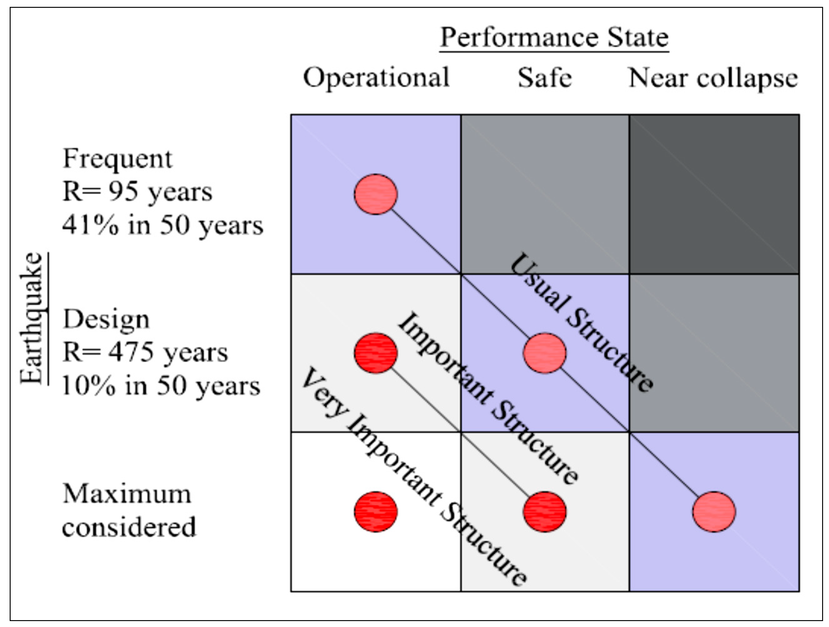
3.1. Seismic Analysis for PEF
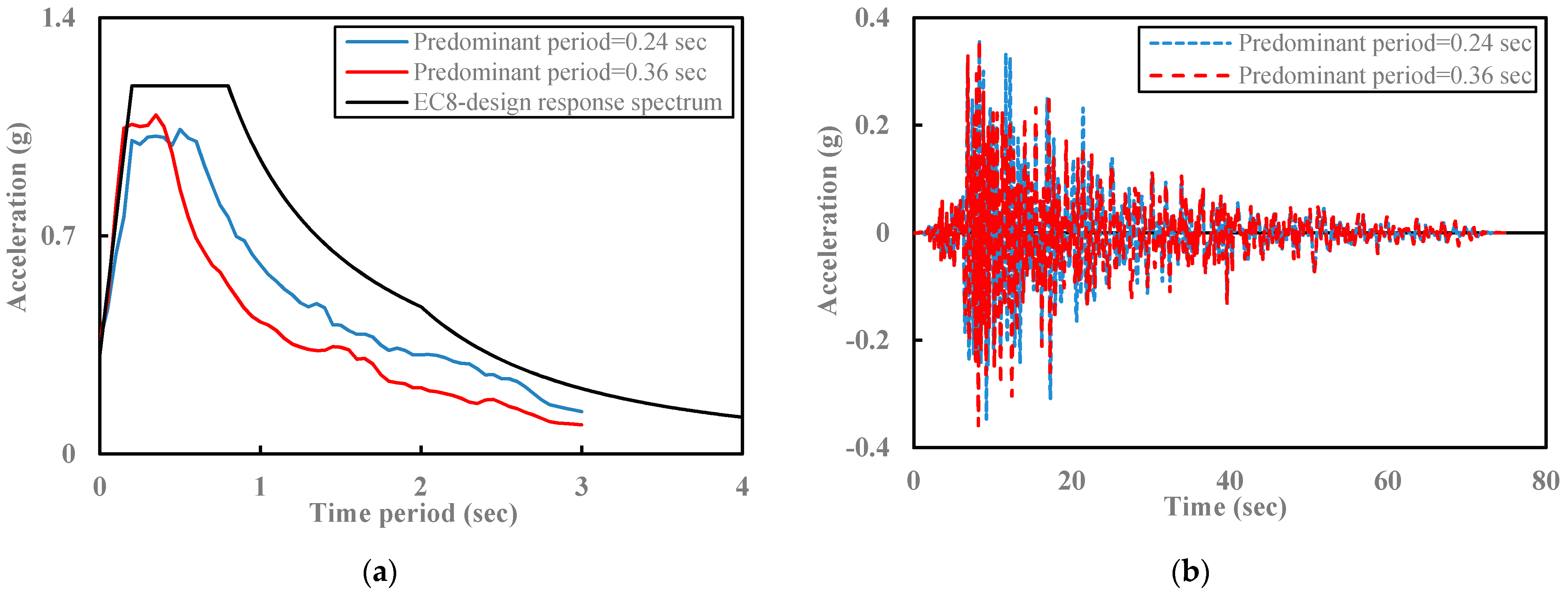
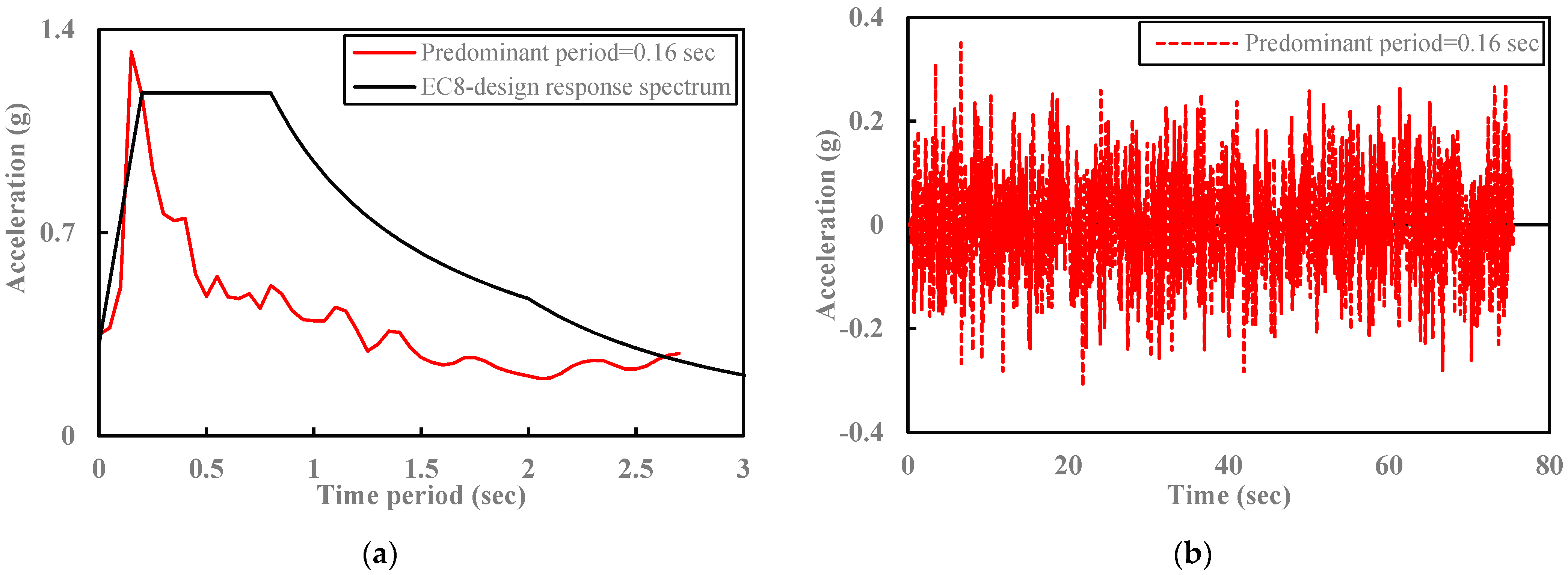
Traditionally, the effects of an earthquake on a structure are studied using either approximate methods, such as a pushover analysis, or a time-history analysis. A pushover analysis is a nonlinear static analysis procedure used to estimate the strength of a structure beyond its elastic limit but does not induce actual plastic damage in the structure and does not require a ground motion time history. On the other hand, a time-history analysis is a nonlinear dynamic response analysis performed using an actual or artificial earthquake to evaluate the response of the system. A time-history analysis usually takes significantly longer to complete compared to a pushover analysis and is also more computationally demanding. However, it provides a more accurate depiction of the structural response to a seismic event, which is imperative in a PEF assessment. When the damage from an earthquake is underestimated, a structure can be highly vulnerable to failure even if it has been rigorously designed for an isolated fire condition. It is in this context, that this study applies a time-history analysis to assess the structural response to the seismic excitation.

3.2. Input Data

The earthquake input data is generated in accordance with the structure frequency modes, geotechnical and geological site properties, and the design response spectrum characteristics. In a performance-based design, a structure subjected to a design earthquake should maintain the required design-level performance [24]. Eurocode 8 specifies two types of earthquakes, namely Type 1 and Type 2 spectra and also four different importance classifications for buildings, depending on their function. In the current work, it is assumed that the structure being analysed has an importance classification of III (i.e., buildings with a seismic resistance that is of importance due to the consequences associated with a collapse, e.g., schools, assembly halls, cultural institutions, etc.) and is therefore subjected to a Type 2 earthquake. The ground conditions are Type E as defined in Eurocode 8, described by various stratigraphic profiles and parameters and with viscous damping set at 5%. For these conditions, the peak ground acceleration (PGA) that occurs during the earthquake is 0.35 g.
The design response spectrum is also developed in accordance with Eurocode 8 for selected targeted time histories. The user-selected time histories are subjected to a scaling and matching procedure to derive earthquake input data within the spectrum periods of interest. The spectral scaling method used in the current study employs a computer algorithm—using SeismoSignal and SeismoMatch software [25]—to modify the real and artificial time histories in order to closely match the target design response spectrum. Using these procedures, data from a real earthquake are modified to a PGA of 0.35 g and a frequency content according to the design conditions.
To examine the seismic structural response, two predominant periods are selected for the modified real earthquake, namely 0.24 sec and 0.36 sec, in addition to one predominant period of 0.16 sec for the artificial motion. For the latter, a MATLAB algorithm has been developed to create the white noise artificial earthquake to satisfy the Eurocode 8 value of the structural natural period; there are more details on this later. The SeismoSignal and SeismoMatch software are combined with data from the U.S. Geological Survey (USGS) peer database [26] to meet the spectral design requirements. Figure 2a illustrates the Eurocode 8 design response spectrum with the modified real earthquake spectra with predominant periods of 0.24 sec and 0.36 sec, respectively, and the corresponding acceleration time histories are shown in Figure 2b. Figure 3 represents the corresponding data for a spectrum with a predominant period of 0.16 sec, for the artificial motion.

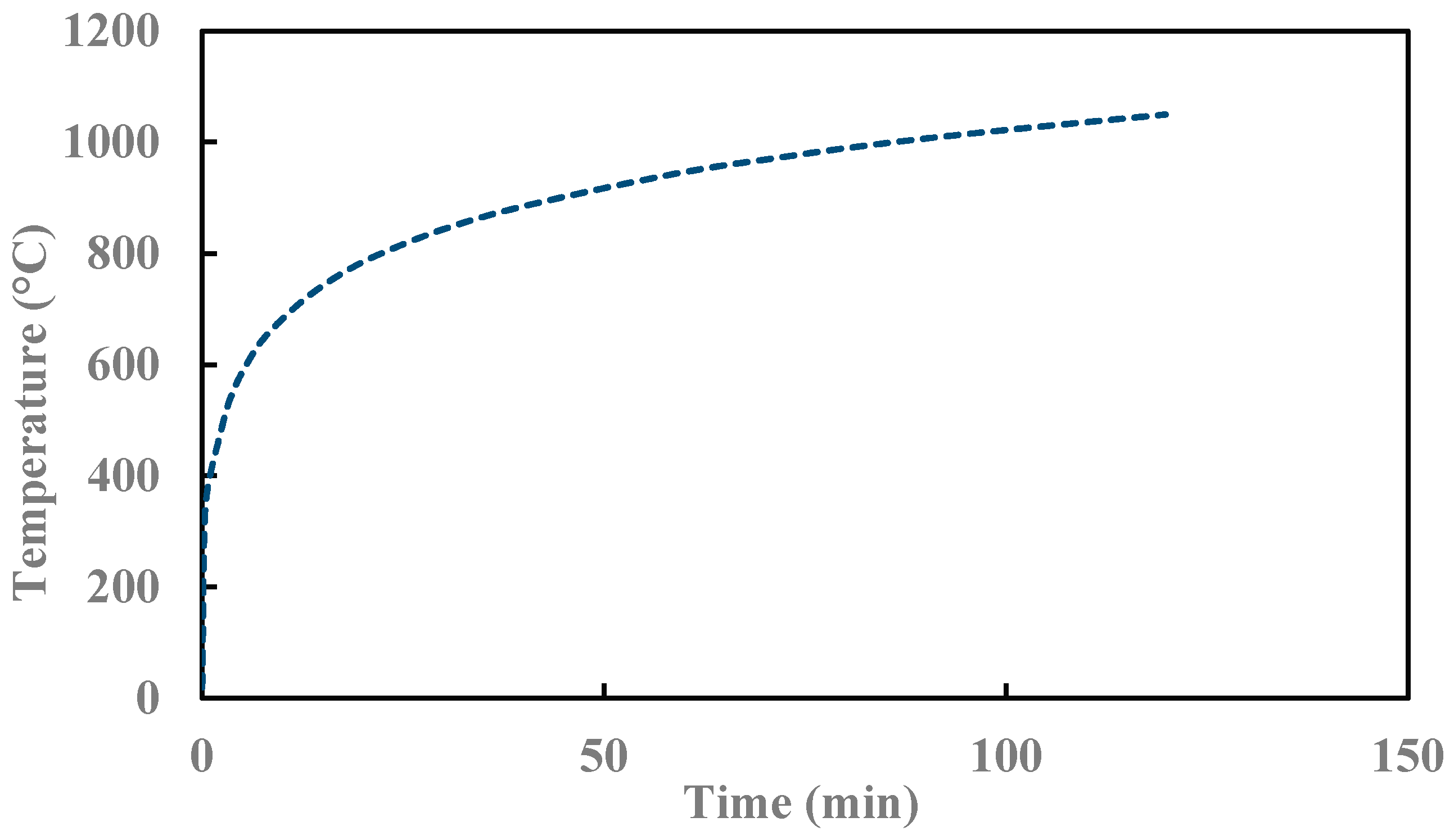
3.3. Thermal Stress Analysis in PEF Analysis

In the post-earthquake fire analysis, the deformed or damaged structural configuration that occurs following the earthquake event is employed as the input for the application of the thermal loads [27,28]. For the fire load, a uniform standard ISO-834 fire exposure [29] is applied to all the components of the frame, as shown in Figure 4. The frame is made from mild steel with a yield and ultimate strength, at the ambient temperature, of 385 N/mm2 and 450 N/mm2, respectively. The steel has a density of 7850 kg/m3 and a coefficient of thermal expansion (αs) of 1.4 × 10⁻⁵. The changes in material properties resulting from increasing levels of elevated temperature are obtained from the reduction factors provided in Eurocode 3 Part 1–2 [7].

4. Development of the Numerical Model

4.1. General

A geometrically and materially nonlinear three-dimensional model of an unprotected single-storey steel frame has been developed using the Abaqus software, in order to analyse the behaviour of the given structure during a post-earthquake fire (PEF). The frame is fabricated from beams and columns of the same I-shaped cross-section, which are connected with rigid joints. The frame is 5720 mm in length, 5370 mm in width and has a height of 4050 mm. The cross-section has a depth (D) of 350 mm, flange width (B) of 170 mm, identical web (t) and flange (T) thicknesses of 10 mm each, root radius (r) of 12 mm and a depth between the flange fillets (d) of 306 mm. The frame is designed to withstand gravity and seismic loads in accordance with Eurocode 8 Part 1 [6]. In accordance with the basis for design information provided in EN 1990 [30] and the guidance on actions in EN 1991 [31], the frame has been designed for a load combination comprising of 100% of the permanent actions and 60% of the variable actions during the PEF event, as discussed later.

4.2. Elements, Meshing and Boundary Conditions

The steel sections are modelled through the finite element model using general purpose linear brick elements with reduced integration, referred to as C3D8R in the Abaqus library [32]. A mesh sensitivity study was conducted to achieve the optimal combination of accuracy and computational efficiency, which resulted in element sizes ranging between 10 × 20 mm and 20 × 20 mm at the beam-column connections and 10 × 100 mm and 20 × 100 mm for the rest of the beam/column steel sections. The steel is represented using a nonlinear elastoplastic material model which has a yield and an ultimate strength of 385 N/mm2 and 450 N/mm2, respectively. These properties degrade with an elevated temperature in accordance with the reduction factors provided in Eurocode 3 Part 1–2 [7]. The beam-column connection is achieved using the tie condition. The base of the columns are assumed to rest on a rigid foundation system, so the earthquake boundary condition is applied at the base of all the columns. A roller support is used to constrain the displacement, placed vertically at the bottom of the model. The horizontal boundary conditions permit ‘free’ horizontal shaking in the direction/directions of the applied seismic load.

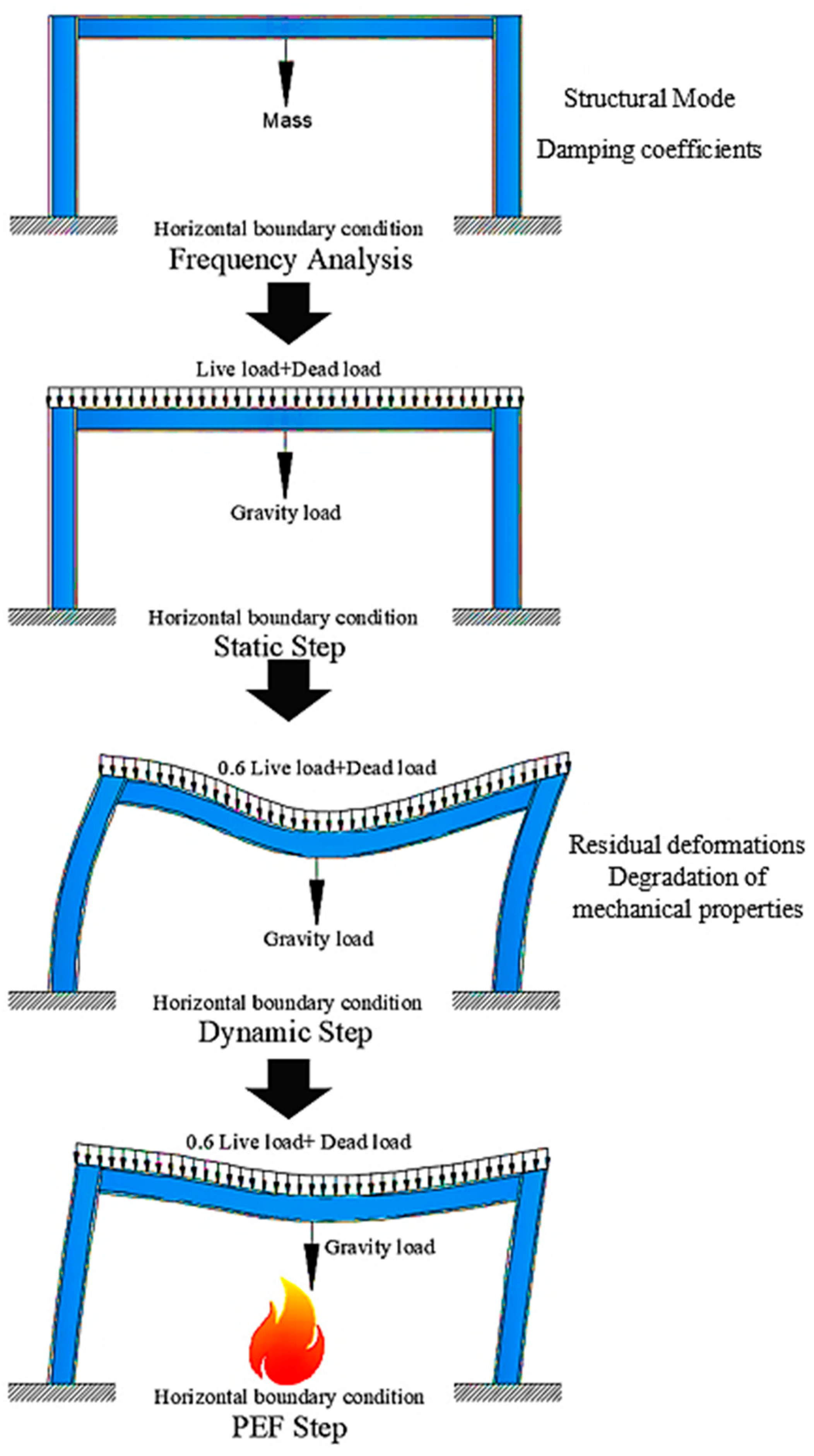
4.3. Loading and Solution Procedure

The analysis is performed sequentially, comprising of static, dynamic and thermal analysis steps, as illustrated in Figure 5. The analysis is carried out in three main multi-hazard analysis steps, as well as an initial sub-step. Firstly, a linear perturbation–frequency step is conducted to identify the structural modal analysis (as discussed in more detail later) and frequency content window of the dynamic system. Then, in the first analysis stage, a nonlinear static analysis is conducted, and the gravity loads are applied. The permanent loads are assumed to have a value of 8 kN/m2 whilst the variable actions are equal to 2.5 kN/m2, in accordance with EN 1991 [31], and all permanent and variable actions are applied. In the second step, the earthquake is simulated through a nonlinear implicit dynamic analysis. The acceleration time history is applied at the base of the structure while the static loads remain constant. The time history is processed, filtering for window frequencies matching the system modes and the natural frequency of the structure during an earthquake with a PGA of 0.35 g. In the third analysis stage, the thermal loads are applied to the deformed structure in the form of a time–temperature curve. The load combination in this stage is considered to be 100% of the permanent loads acting together with 60% of the variable actions [31]. The overall analysis is performed in a sequence to carry forward the deformations, stresses and damage caused to the structure during one stage to the next stage of the analysis. The key objective of the current study is to compare between the structural behaviour of structures subjected to a multi-hazard event with the behaviour of those exposed to a fire-only scenario. Thus, to compare with and examine the consequences of an earthquake directly preceding and possibly causing a fire, a fire-only event is also studied.

5. Results and Analysis

In this section, the results of the finite element analysis are presented and discussed. The first results presented are for the frequency analysis, in which a linear perturbation-frequency analysis is developed as a sub-step of analysis, followed by the results from the PEF structural simulations.

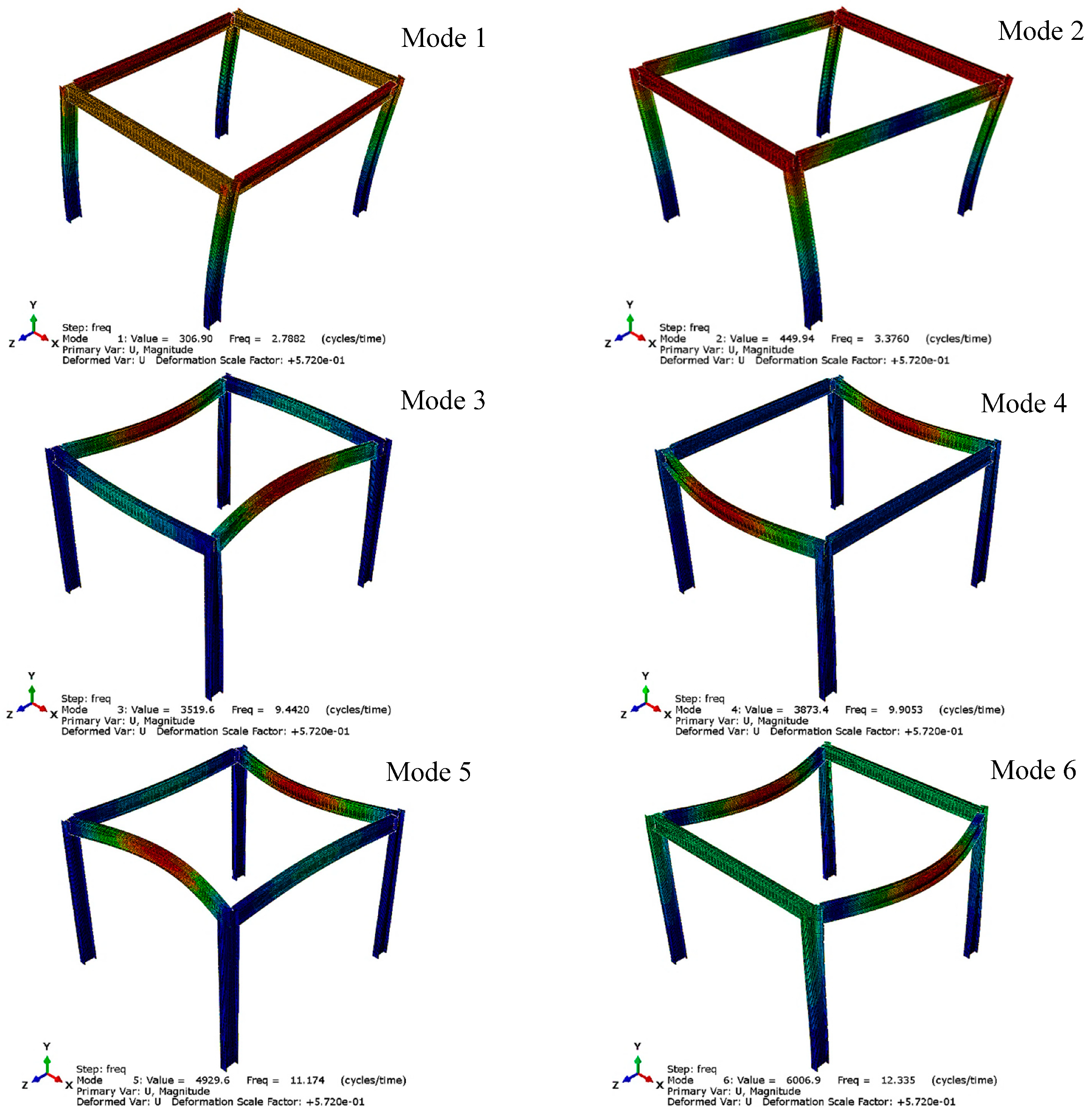
5.1. Frequency Analysis

The natural period of vibration of a dynamic system is an essential factor for the force-base design methodology ([33,34,35]). In this method, the base shear is the expected ultimate lateral load applied at the base of the structure during seismic activity. The natural period of vibration is a critical parameter in defining the design response spectrum and consequently in controlling the value of the base shear force. Hysteretic damping is applied in the restoring force, and viscous damping is considered by Rayleigh (proportional) damping, as provided in Equation (2):
[ C ] = α M   [ M ] + β K   [ K ]
where α M   and   β K are the mass and stiffness proportional damping coefficients, and [M], [K], and [C] are the mass, stiffness, and damping n × n matrices, respectively. The damping ratio of the system for different natural frequencies (ξi) can be determined using Equation (3):
ξ i = 1 2   [ α c ω i + β c ω i ]
In this expression, ω i   is the system-mode frequency. Owing to the orthogonality between the system mode and damping matrix, as well as the assumption of 5% damping for the system modes, the corresponding mass and stiffness coefficients of Rayleigh damping are calculated using Equations (4) and (5), respectively:
α M = 2 ω i ω j ω j 2 ω i 2   ( ξ i ω j ξ j ω i )
β K = 2 ( ξ j ω j ξ i ω i ) ω j 2 ω i 2
where ω i   and   ω j are any two system-mode frequencies and   ξ i   and   ξ j are the damping ratio at ω i   and   ω j , respectively. International design codes provide empirical formulae to estimate the fundamental period of vibration T of the structure. Eurocode 8 Part 1 [6] recommends using the Rayleigh method, as presented in Equation (6):
T = 2 π i = 1 n ( m i · S i 2 ) i = 1 n ( f i · S i )
in which m i   represents storey mass, f i represents horizontal forces, and S i is the displacement of masses caused by horizontal forces. The first six natural vibration periods, the damping coefficients, and the natural vibration period of the system have been computed based on a linear perturbation-frequency analysis in accordance with EN 1998-1, and the findings are shown in Table 1. Figure 6 presents the corresponding mode shapes. In addition, Table 1 presents each of these natural vibration periods together with the value determined using EN 1998-1. The data presented in Table 1, together with the mode shapes in Figure 6, indicate that the first natural period, computed according to Eurocode 8 provisions, (0.16 sec) is between the second (0.296 sec) and third (0.106 sec) mode of the simulated values. It is also evident that the estimated natural period values decrease significantly for the first two modes after which the reduction changes more gradually for the remaining modes. Due to this, it has been concluded that it is important to consider more modes than just the first mode of the system in the seismic analysis, as has traditionally been the case. Accordingly, three input motions are considered in this paper, with natural vibration periods of 0.24 sec, 0.36 sec and the Eurocode 8 value of 0.16 sec, respectively.

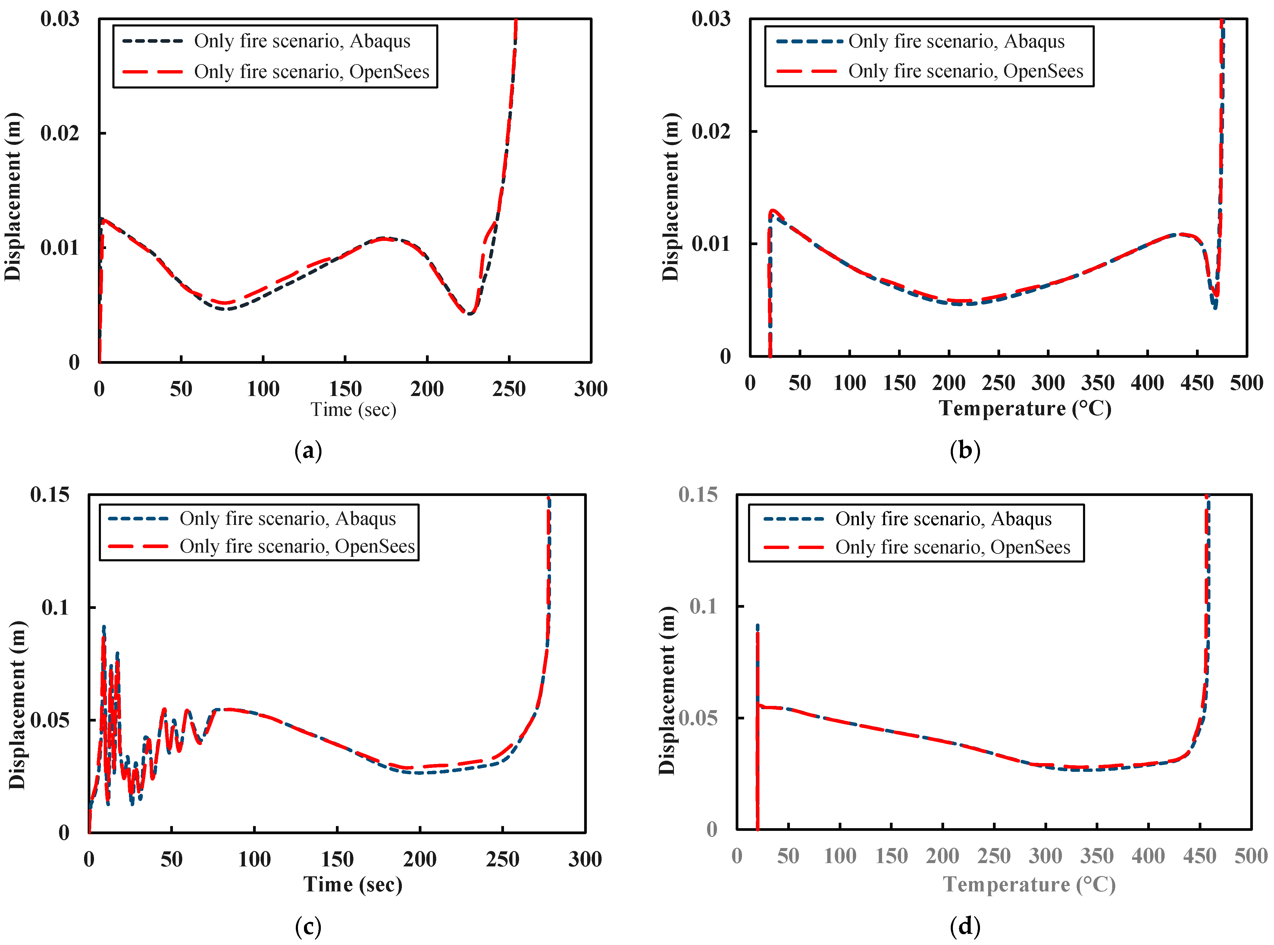
5.2. Validation Study

Owing to a dearth of physical test data on a complete 3D structure, the numerical model is validated through a previously verified modelling approach, using the OpenSees FE software [14]. OpenSees (Open System for Earthquake Engineering Simulation) was initially developed at the University of California, Berkeley for seismic loading analysis [36] and was later extended to perform structural fire analyses at the University of Edinburgh [37]. Usmani et al. [37] found that OpenSees is capable of providing an accurate depiction of structural performance during fires. In this study, an identical steel frame has been modelled using OpenSees, and the results are presented in Figure 7, including (a) the time-displacement response for the fire-only scenario, (b) the temperature-displacement response for the fire-only scenario, (c) the time-displacement response for the PEF scenario and (d) the temperature-displacement response for the PEF scenario. All of the presented results are obtained from the mid-span location and the results from both the Abaqus and OpenSees models are presented. It is clear that both models and approaches provide almost identical results.

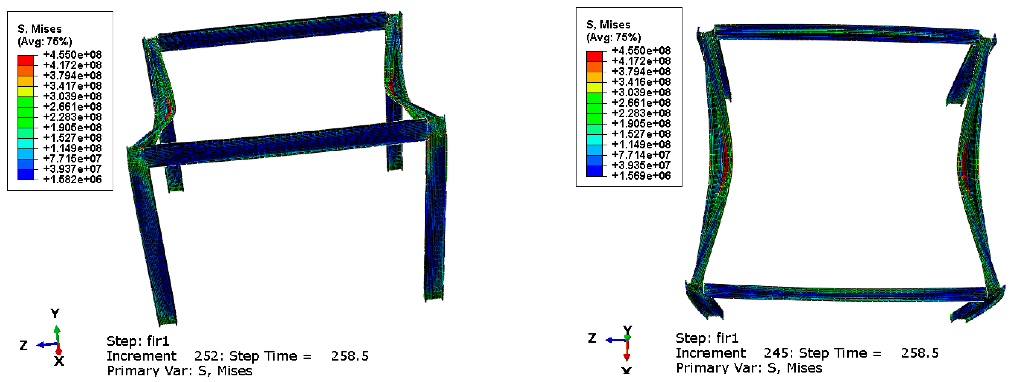
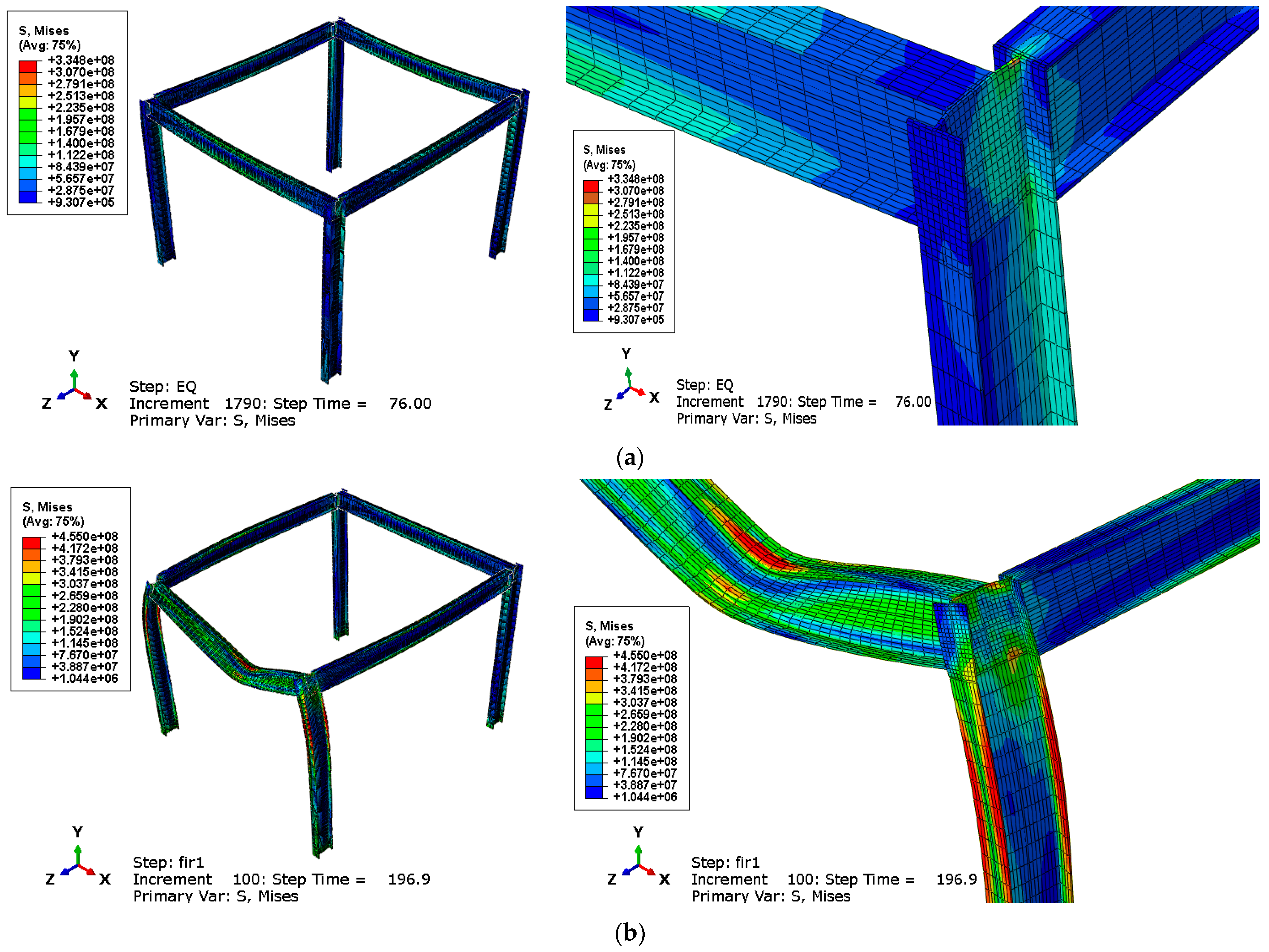
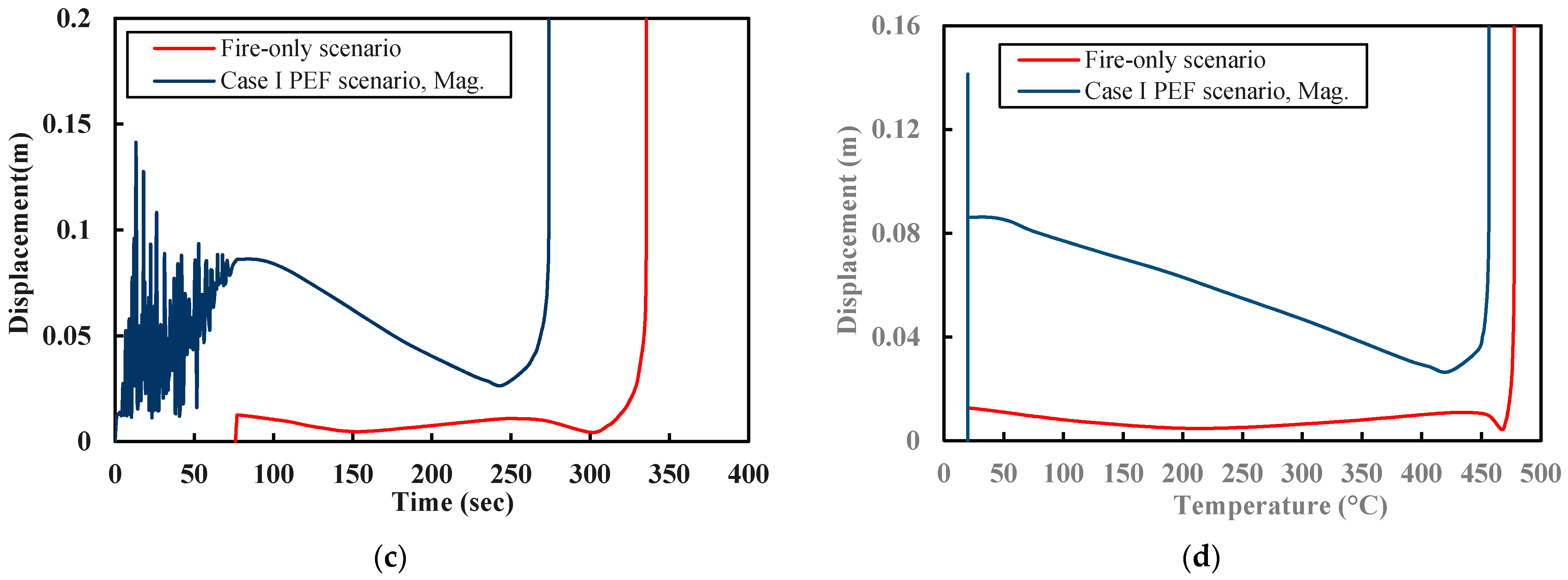
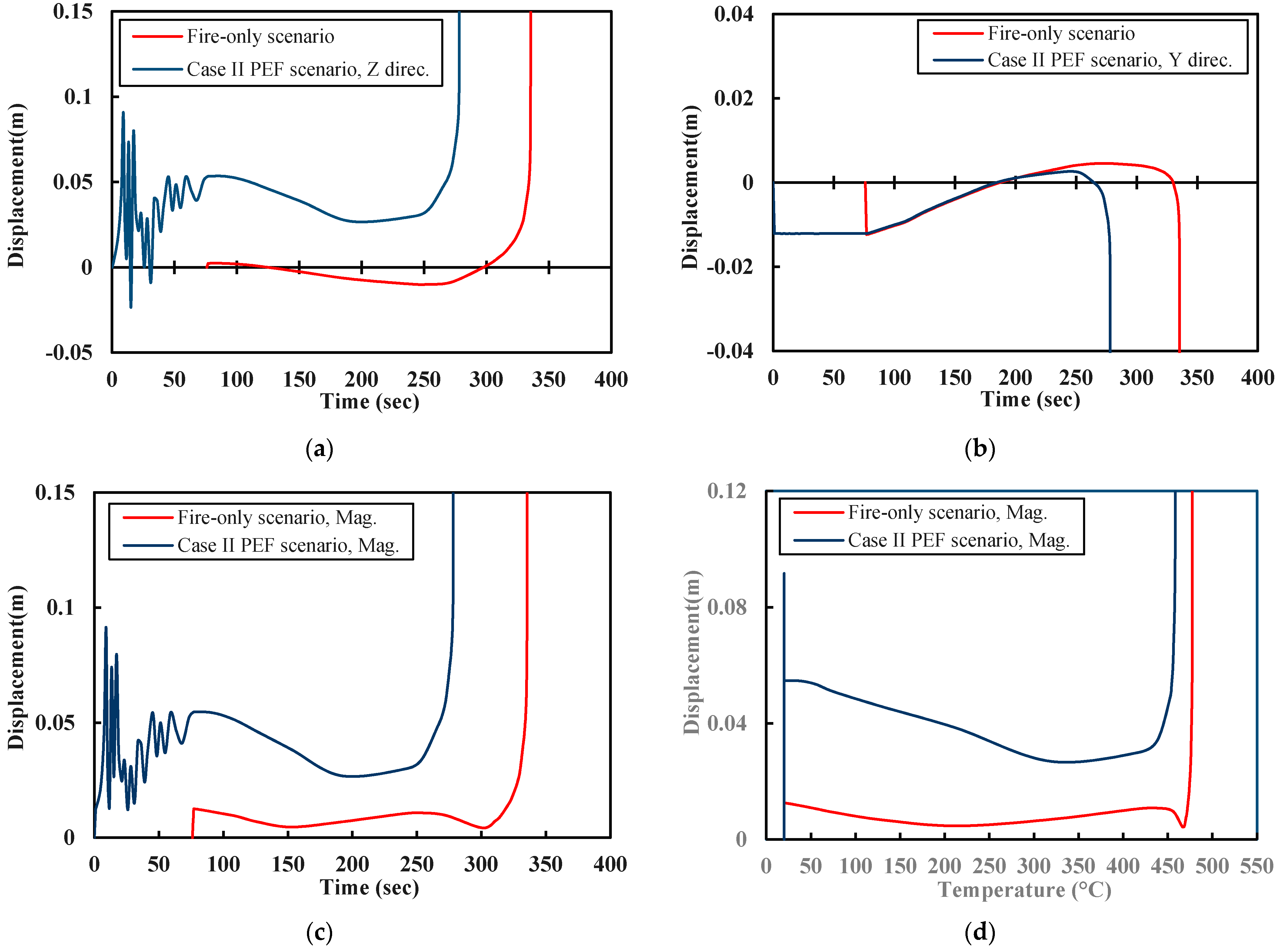
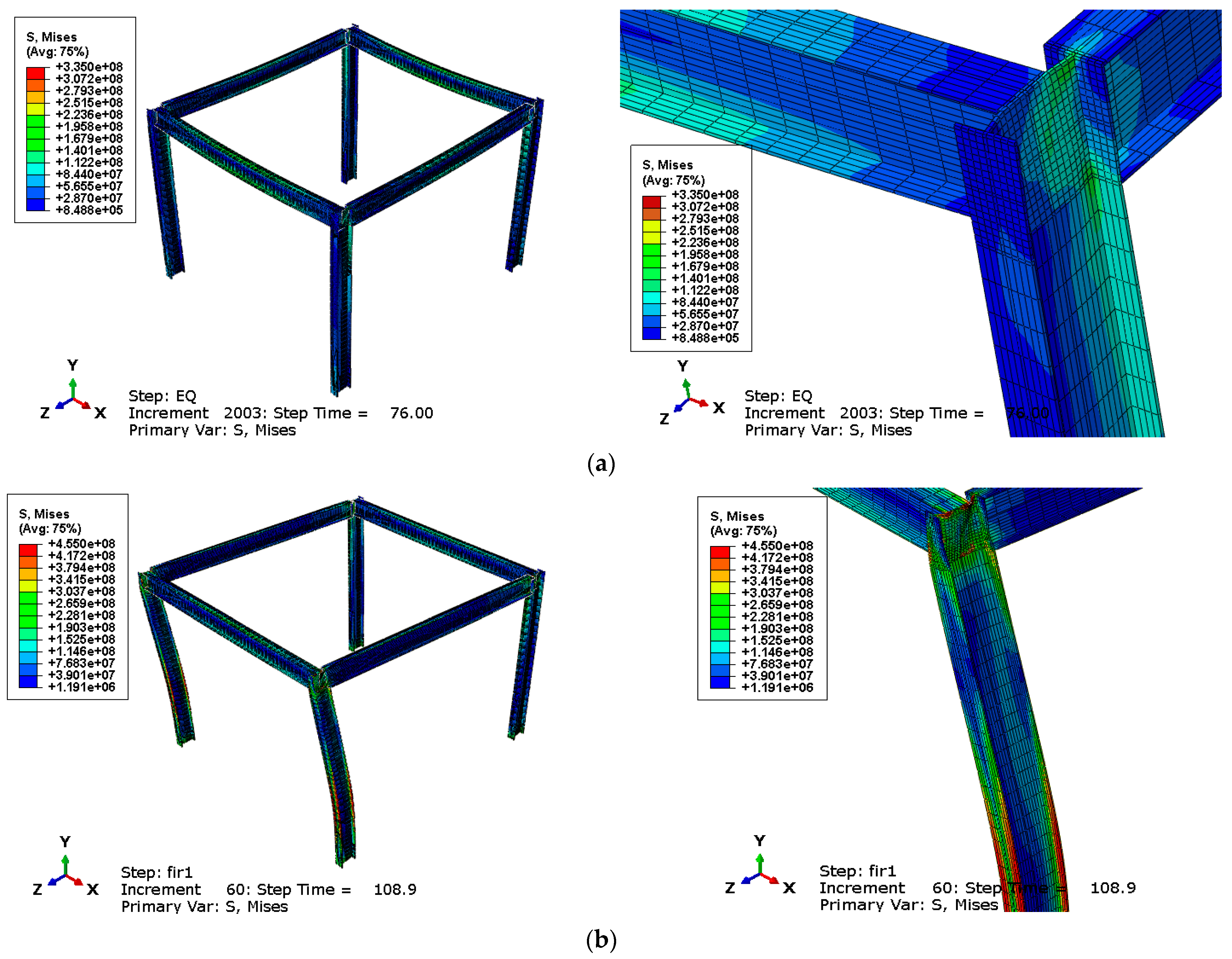
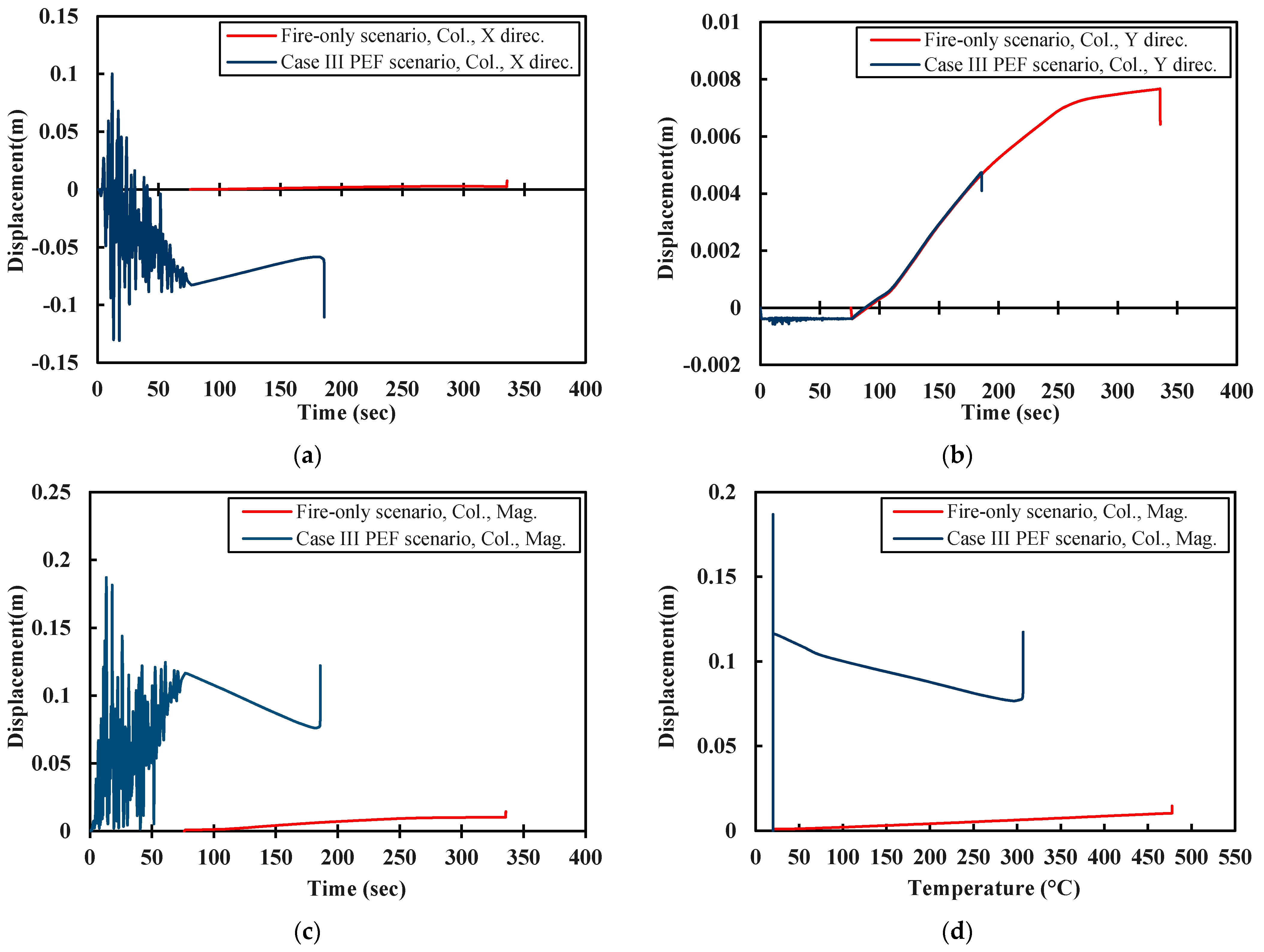
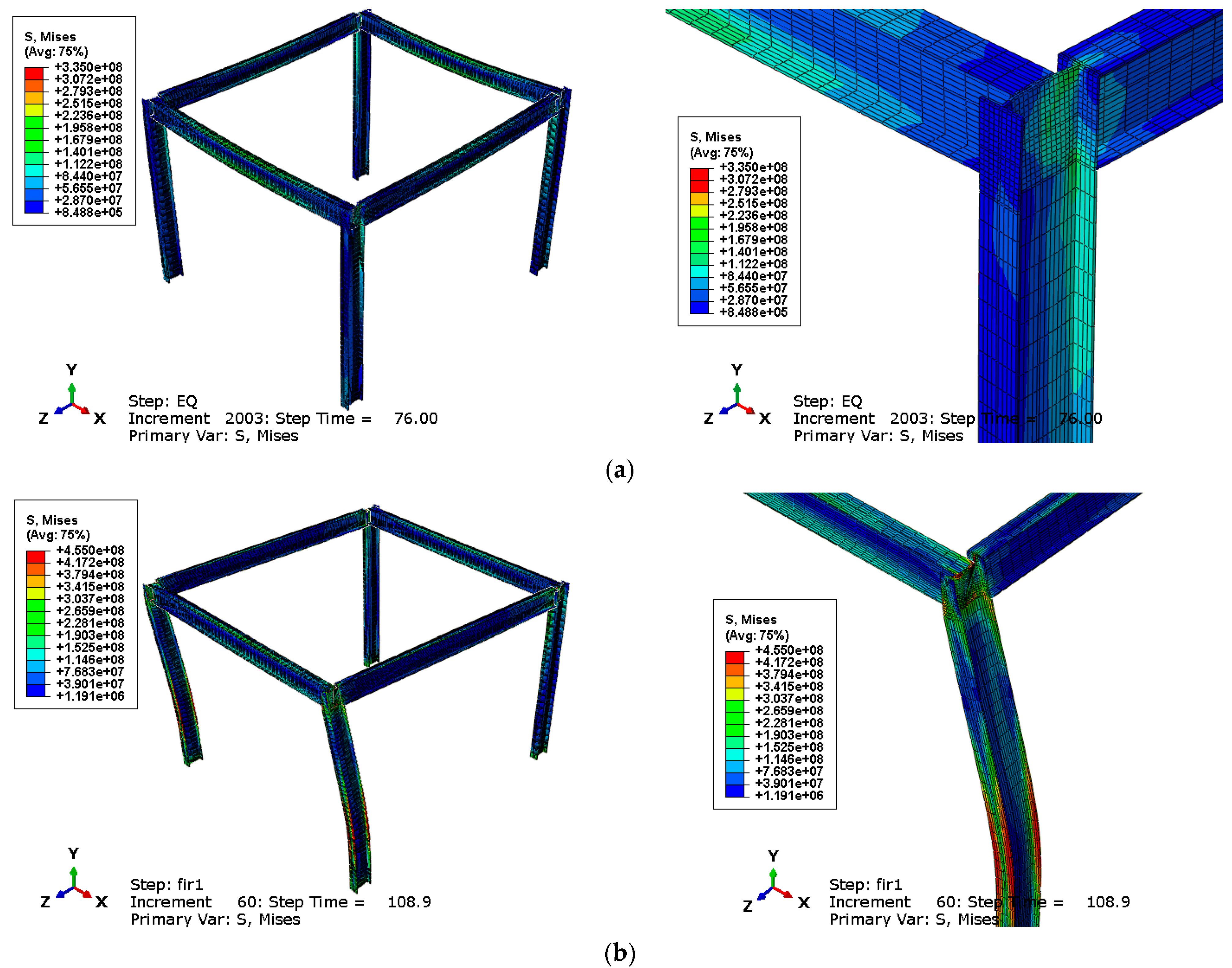
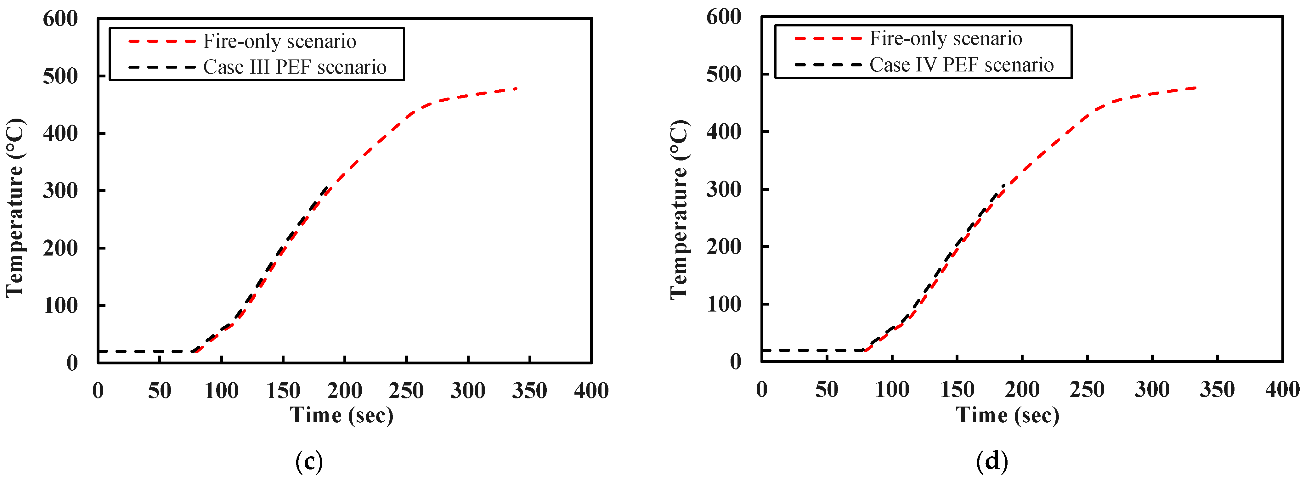
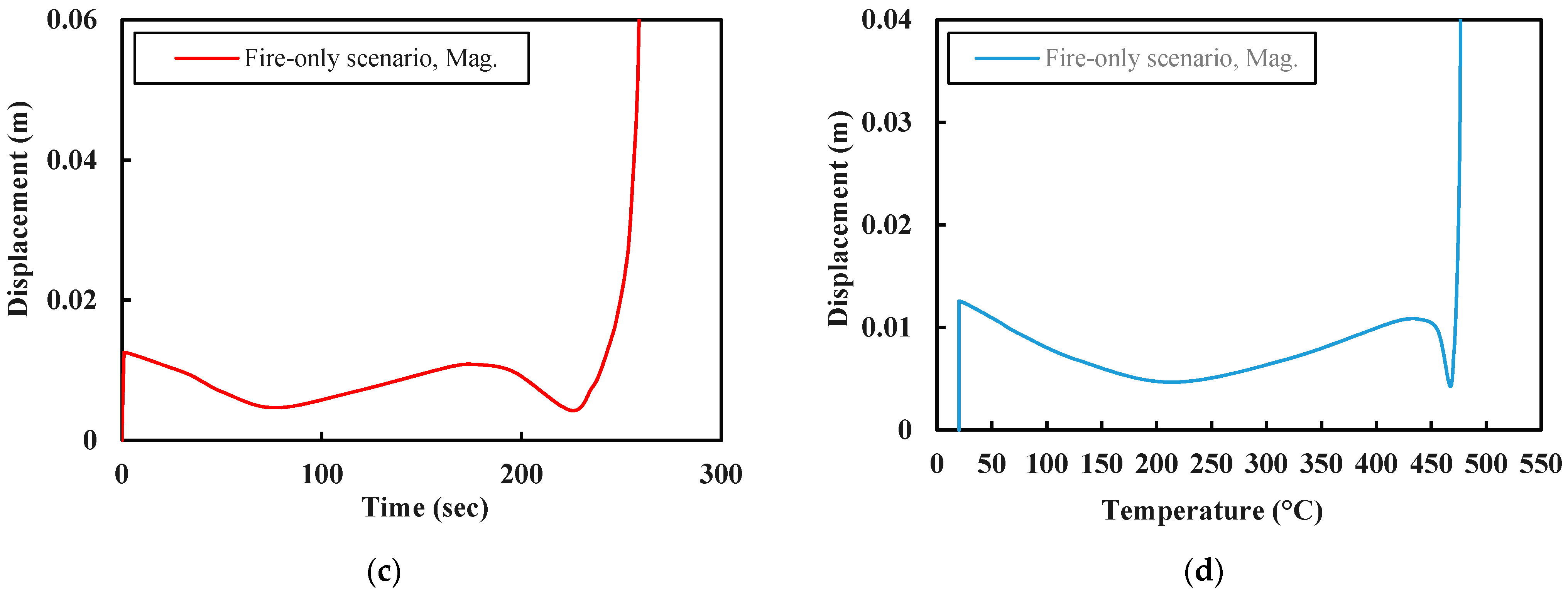
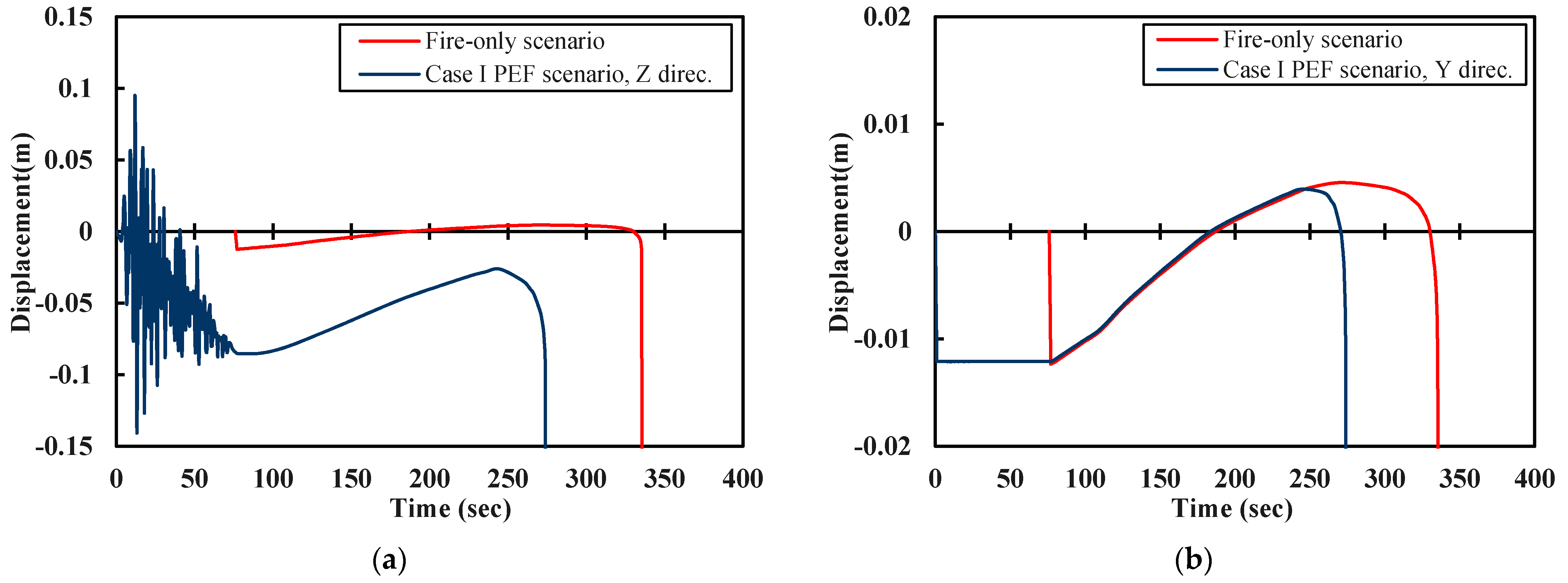
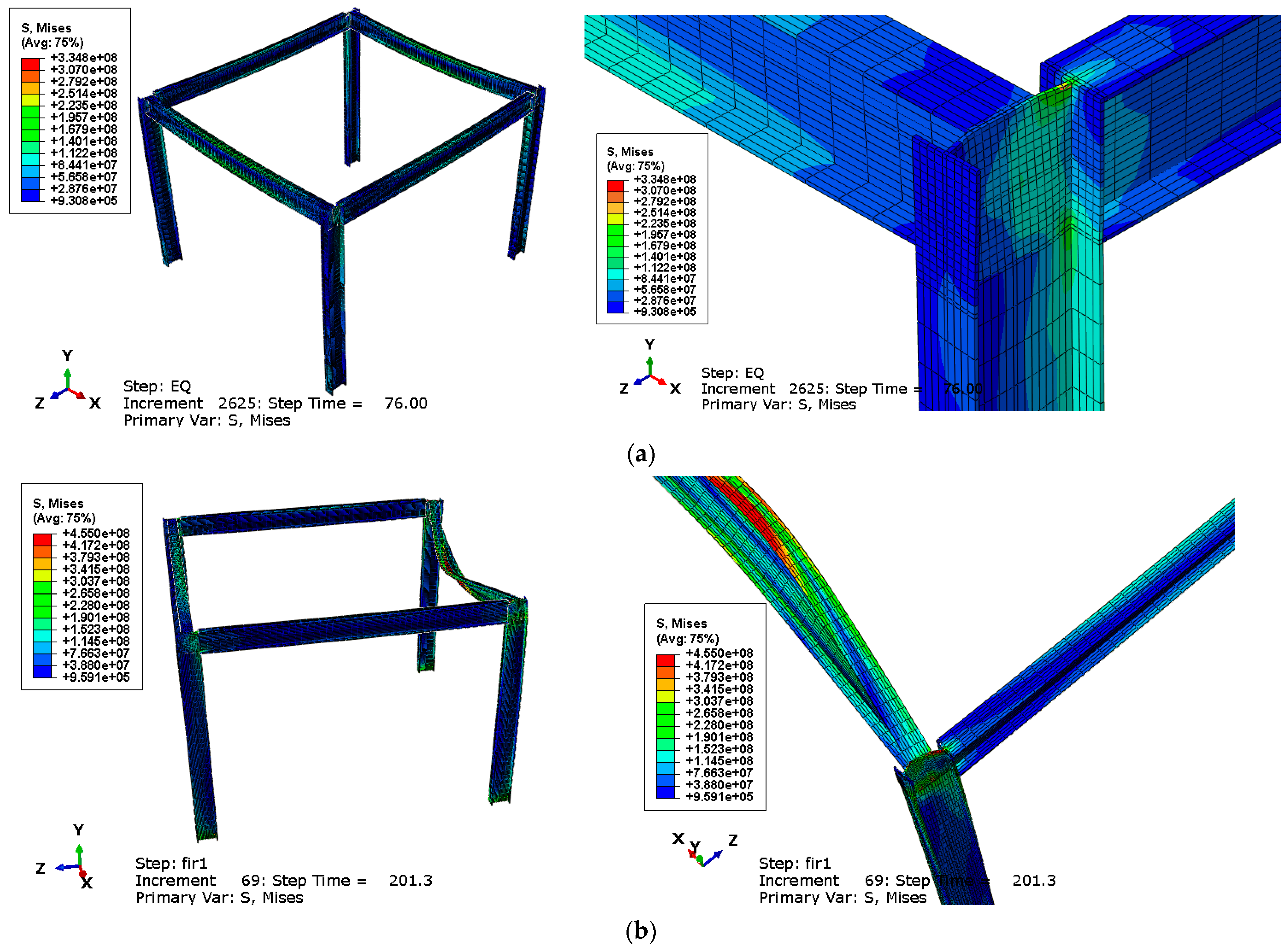
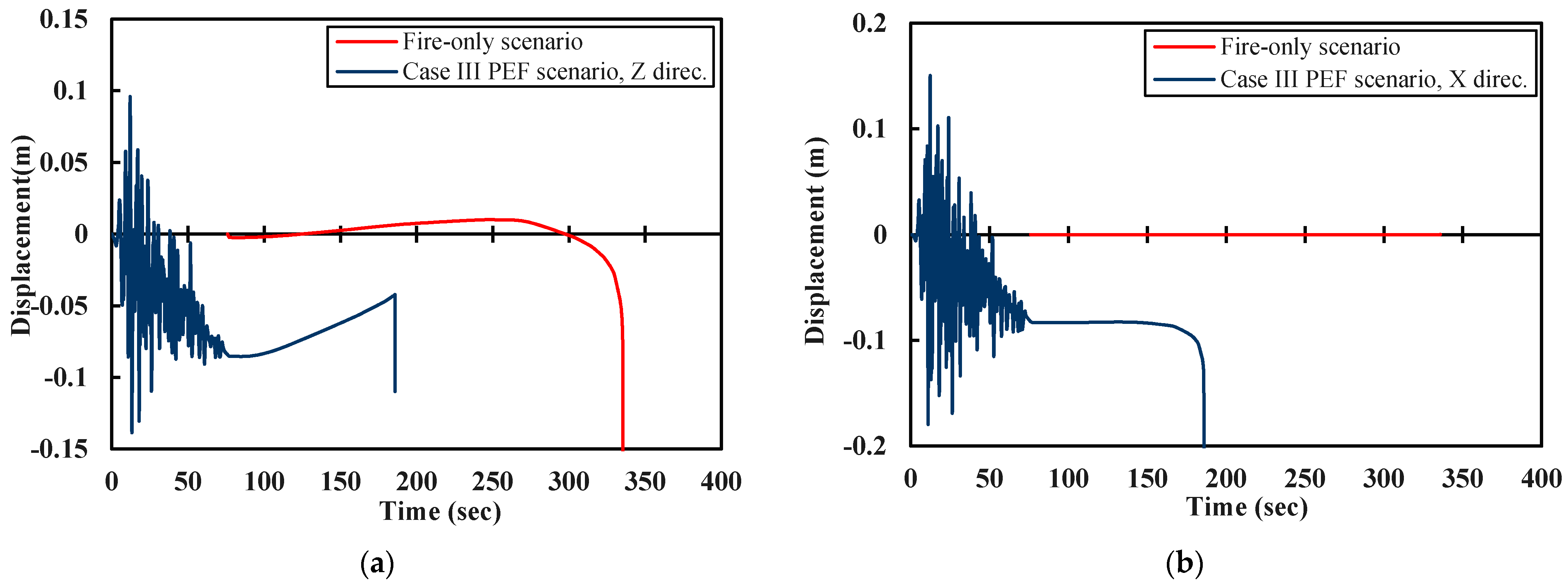
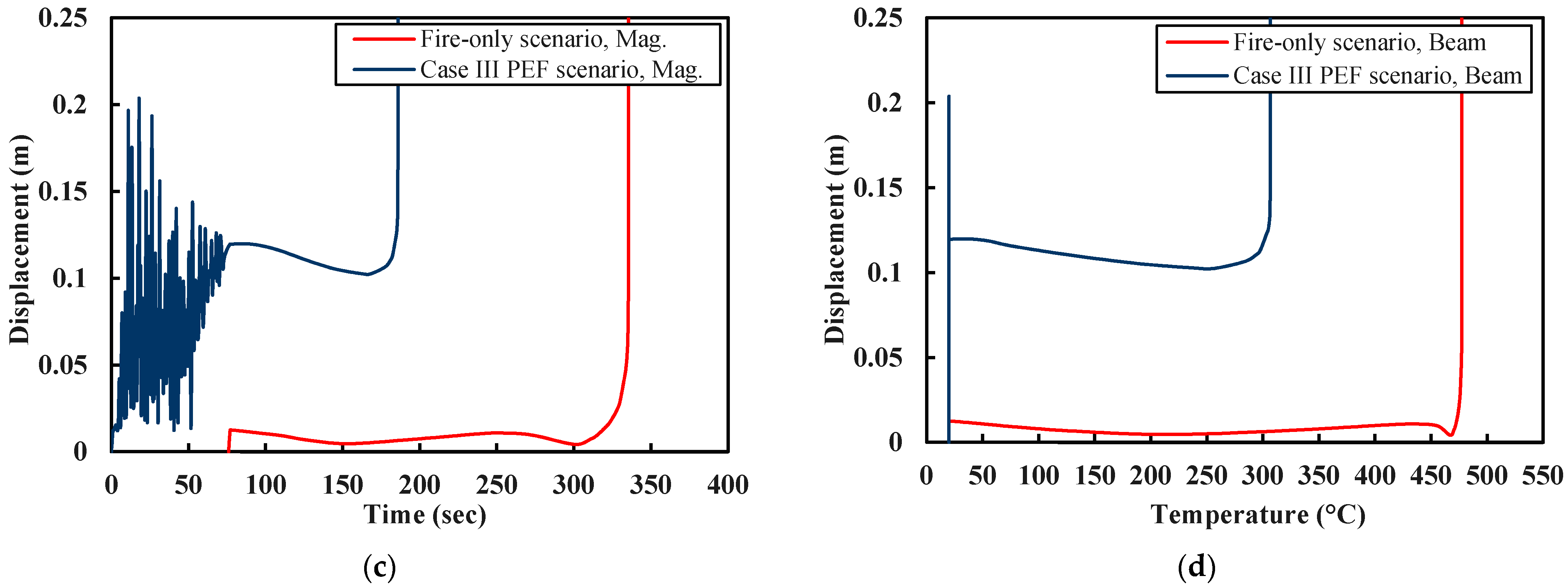
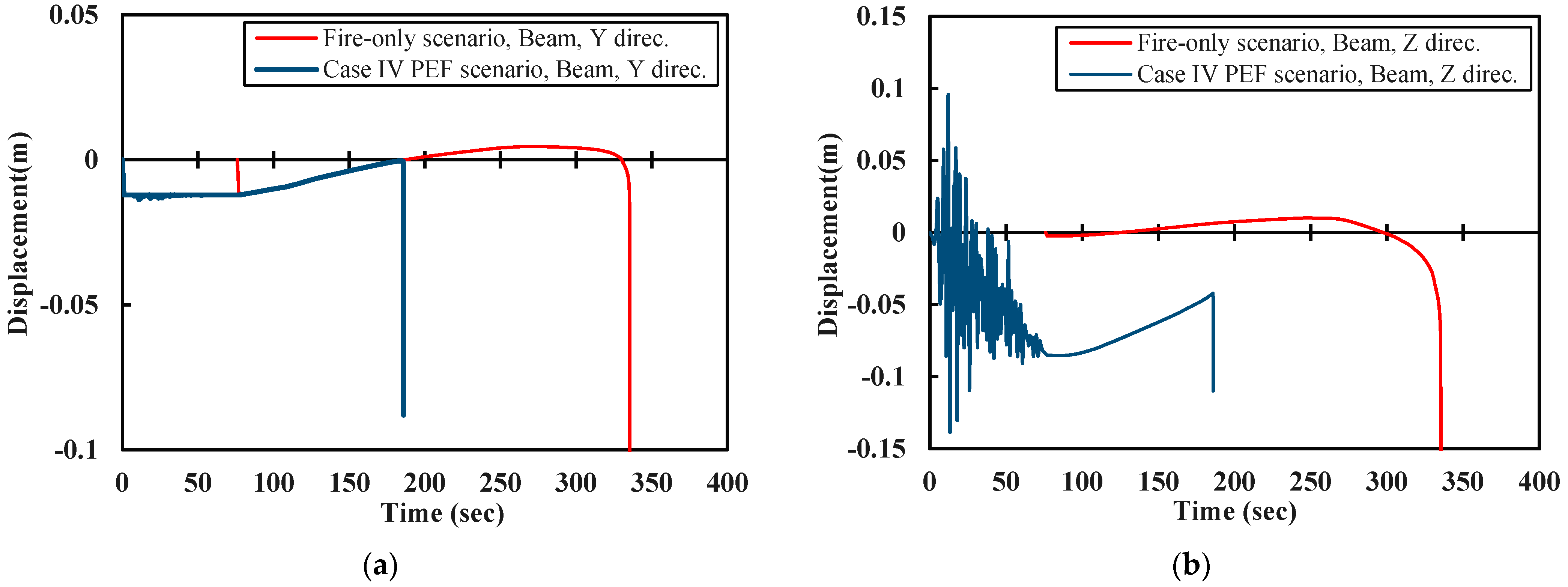
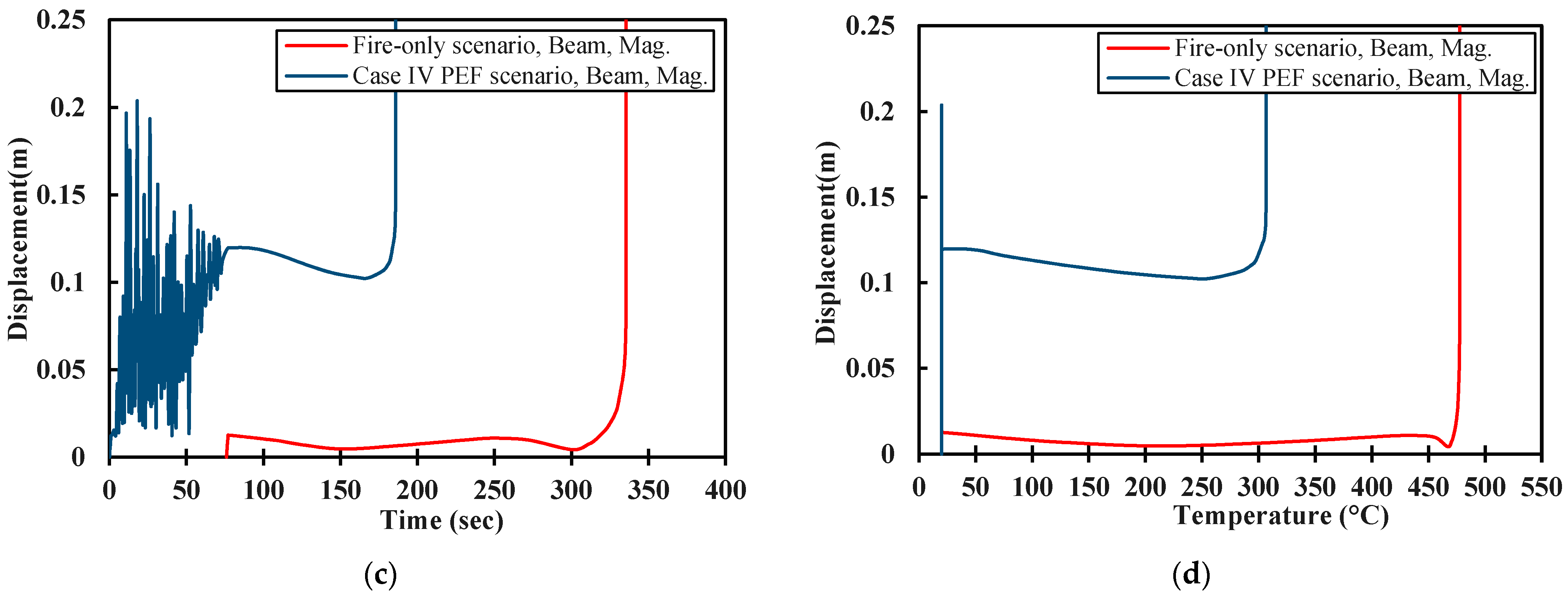
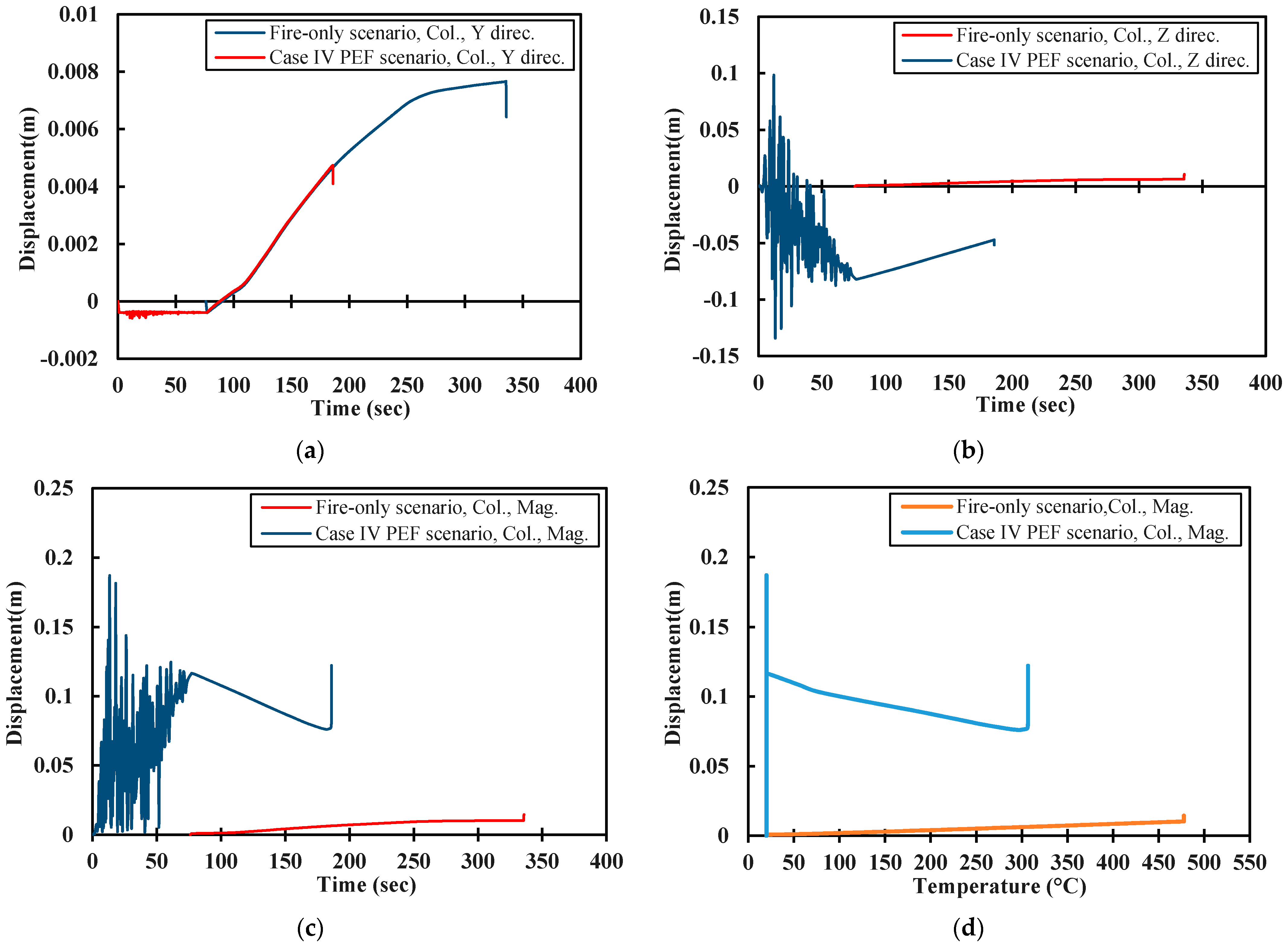
5.3. Post-Earthquake Fire

In this section, the FE model developed in Abaqus that has been previously described is employed to assess and understand the post-earthquake fire (PEF) behaviour of steel framed structures. As stated before, the nonlinear sequential analysis [5] comprises a static stage, followed by the time history earthquake analysis after which the fire is applied. In the seismic analysis, the structure is subjected to two different time-history motions (referred to a Case I and Case II, respectively) which are matched to a particular predominant natural vibration period in accordance with the time period window resulting from a frequency analysis, as well as the natural period computed according to Eurocode 8 guidance. In addition, to replicate a real earthquake situation as accurately as possible, two types of excitation are applied, including unidirectional and bidirectional excitations for the different natural periods. Eurocode 8 requires that structures remain operational following relatively frequent earthquake events without incurring significant damage and incurring no structural damage. As such, the code defines an acceptable degree of reliability and validity for acceptable damage which must be reviewed during the design stage. The storey drift criterion is one of the primary stability criteria used in seismic codes and the Eurocode 8 limit is specified as 1% of the storey height under the ultimate design earthquake, which is 0.03 m in the present study.
In order to understand how an earthquake impacts upon a structure’s fire resistance, a series of fire-only analyses are first presented. Figure 8 illustrates the collapse mechanism for a steel frame following a fire whilst Figure 9 shows the time-displacement and temperature-displacement curves, respectively, for the fire-only scenario. It is observed that local failure occurs concurrently for the two opposing beams in a symmetrical manner. The failure occurred around 260 sec after the fire began and at a temperature of approximately 480 °C.
The results from the PEF analysis for Case I, which involved an artificial earthquake, with a PGA of 0.35 g and a predominant natural vibration period of 0.16 sec, exposed to excitation in the Z direction, are presented in Figure 10 and Figure 11. Figure 10 presents (a) the residual deformation that the steel frame experiences due to the earthquake excitation as well as (b) the shape and mechanism of failure of the structure (in the beam) after the PEF event for Case I. Whereas, Figure 11 presents the time-displacement results in the (a) z-direction, (b) y-direction and (c) the total displacement value respectively, as caused by PEF loading, as well as (d) temperature total displacement results due to PEF, for the case I scenario. The data from the corresponding fire-only analysis is also provided in these images.
The results indicate that the structure maintains the earthquake force successfully, experiencing geometrical and mechanical damage within the acceptable range of Eurocode 8. However, in comparison with the images for the fire-only scenario provided in Figure 10, it is clear that the failure shape in the PEF case is no longer symmetrical. In addition, the collapse occurs after just 272 sec, which is a 19% reduction from the fire-only case, and at a temperature of 455 °C. The storey drift value at collapse is 0.024 m and therefore remains within the 0.03 m limit stipulated by Eurocode 8. The corresponding results for the Case II scenario (PGA of 0.35 g and a natural period of 0.36 sec) are presented in Figure 12 and Figure 13, respectively. It is clear that the failure mechanisms are unsymmetrical, and in this case, collapse occurs after 278 sec and at a temperature of 458 °C, which is almost identical to Case I.
The data presented for both Case I and Case II reflect the effect of an earthquake on the fire strength of the structure during unidirectional excitation. This kind of the excitation does not represent the situation of earthquake excitation in reality, which is also typically unidirectional. Due to this, more observations are obtained by examining the structural response to bidirectional excitation for a further two real and artificial motions (Cases III and IV, respectively).
Figure 14 and Figure 15 present the results from the analysis of a Case I earthquake with bidirectional excitation in both the x- and z-directions (referred to as Case III); these figures are presented in a similar format as before, for the purpose of comparison. It is clear that the global failure mechanism is dominant due to the combined effects of bidirectional excitation and the PEF event. The columns of one side of the structure completely collapsed in this scenario. The displacement records at a level of 1.4 m along the column length, for both the fire-only and PEF events are compared in Figure 16, which presents the time-mid-span displacement results at this position in (a) the x-direction, (b) the y-direction and (c) of the total displacement, respectively. Figure 16d presents the temperature-displacement response at the same point, 1.4 m from the column base. For this case, with bidirectional excitation, failure occurred after just 185 sec and at a temperature of 306 °C, representing a reduction of 45% compared with the fire-only analysis. The storey drift was 0.118 m, exceeding the allowable Eurocode 8 value. Similar behaviour and results are observed for Case IV, which has an identical input motion as Case II except with bidirectional excitation in both the x- and z-directions. The corresponding results are provided in Figure 17, Figure 18 and Figure 19, in a similar format as before. It is clear that there is a significant reduction in the failure time for the PEF situation in Case IV of approximately 45% (to 185 sec) as well as a storey drift of 0.115 m, exceeding the allowable Eurocode 8 limit value by 85%. Significant local and global failure occurs in this case, preventing the structure from withstanding the applied loads.
In this section, a detailed numerical investigation into the behaviour of a steel-framed subject to a PEF event is presented. Structural damage, residual deformation, and stress degradation as result of earthquake excitation are considered and included in the multi-hazard analysis. Two different types of structural failure due to the effect of the combined hazards are observed, namely local and global failure. The failure times for all of the analysed cases are compared to the corresponding values from a fire-only analysis in Figure 9, Figure 11, Figure 13, Figure 15, Figure 16 and Figure 18. In addition, Figure 20 presents a comparison of the fire-only analysis versus the PEF analysis for each of the four analysed cases (I–IV). It is shown that the geometrical and mechanical damage induced by an earthquake event can substantially decrease the fire resistance of the structure, specifically in the occurrence of bidirectional excitation (see Table 2). This observation has a significant consequence on the design aspects of the system for multi-hazard analysis. The design load combination, the number of structural modes incorporated in the seismic design as part of the multi-hazard investigation and the structural element section type are very influential parameters. Although the current study has not included a detailed investigation of the effects of different cross-section shapes, specifically tubular members, the results presented provide a valuable insight into the significant effects of a PEF event on a steel framed structure, and also on the importance of choosing a suitable column section in earthquake-prone zones. Furthermore, based on these results, it is proposed that using tubular sections is essential in earthquake zones to provide extra resistance in a PEF scenario, even though other sections may satisfy the seismic design requirements (that do not consider PEF). This is clearly an area that requires further research. Further, the load combinations provided in international codes do not currently include provisions for post-earthquake fire and each event is considered completely independently. The results presented herein do not support such an approach.

6. Conclusions

This paper presents a detailed analysis of the influence of a post-earthquake fire on the behaviour of a steel framed building. It is clear that there are grave consequences in terms of occupant and structural safety during this type of multi-hazard scenario. Therefore, an accurate analysis of the response of structures exposed to such an event is required at the design stage, especially for very important buildings. The likelihood of a fire occurring following an earthquake is reasonably high, despite PEF being the subject of relatively little research in the available literature. In most design codes, structures exposed to multiple hazards such as earthquakes and then fires are analysed and designed separately. Structures subjected to an earthquake experience partial damage, and the subsequent occurrence of a fire may lead to structural collapse. Most available analysis procedures and design codes do not address the association of the two hazards. Thus, the design of structures based on existing standards may present a high risk of structural failure.
A suitable method of analysis has been developed in this paper to investigate the behaviour of structures that are exposed to such sequential hazards. Investigating the effects of PEF on structures classified as “ordinary” in the design codes (such as educational and residential buildings, for example) is necessary as these types of building are very common in urban and well-populated environments. A performance-based design consideration requires structures to remain within the ‘life safety’ level of response under the design for the occurrence of an earthquake and fire, separately. In the current paper, two types of failure mechanisms are detected for steel framed buildings subjected to PEF—global and local failure. Local failure happens in the beams, whereas global failure is evidenced by significant lateral movement in the columns due to bidirectional excitation. Interestingly, the majority of the fire-only analyses discussed herein resulted only in a local collapse, while all of the PEF analyses with bidirectional excitation resulted in a global collapse. Therefore, it is clear that the failure mode for a PEF can be quite different compared to a single hazard event. Consequently, it is suggested that columns with greater bi-directional stiffness (e.g., tubular sections) are likely to offer the greatest ultimate resistance in earthquake hazard zones under the combined effects of bidirectional earthquake excitation and subsequent fire. Despite the investigations in this paper being performed in relation to a particular class of structures, the results confirm the need to incorporate PEF as a load case during both the analysis and design stages. Further studies need to be performed either numerically or experimentally, using complete a seismic soil-structure interaction analysis, to develop a better understanding of the issue.

Author Contributions

Conceptualization, A.T.A. and P.E.F.C.; Methodology, A.T.A. and K.A.C.; Software, A.T.A.; Validation, A.T.A., P.E.F.C. and K.A.C.; Formal analysis, A.T.A.; Investigation, A.T.A.; Data curation, A.T.A., P.E.F.C. and K.A.C.; Writing—original draft preparation, A.T.A.; Writing—review and editing, P.E.F.C. and K.A.C.; Visualization, A.T.A.; supervision, P.E.F.C. and K.A.C.; project administration, P.E.F.C. All authors have read and agreed to the published version of the manuscript.

Funding

This research received no external funding.

Institutional Review Board Statement

Not applicable.

Informed Consent Statement

Not applicable.

Data Availability Statement

The study did not report any data.

Conflicts of Interest

The authors declare no conflict of interest.

References

  1. Chicchi, R.; Varma, A.H. Research review: Post-earthquake fire assessment of steel buildings in the United States. Adv. Struct. Eng. 2018, 21, 138–154. [Google Scholar] [CrossRef]
  2. Li, G.Q.; Zhang, C.; Jiang, J. A review on fire safety engineering: Key issues for high-rise buildings. Int. J. High-Rise Build. 2018, 7, 265–285. [Google Scholar] [CrossRef]
  3. Yassin, H.; Iqbal, F.; Bagchi, A.; Kodur, V.K.R. Assessment of Post-Earthquake Fire Performance of Steel-Frame Buildings. In Proceedings of the 14th World Conference on Earthquake Engineering, Beijing, China, 12–17 October 2008. [Google Scholar]
  4. Ronagh, H.R.; Behnam, B. Investigating the Effect of Prior Damage on the Post-Earthquake Fire Resistance of Reinforced Concrete Portal Frames. Int. J. Concr. Struct. Mater. 2012, 6, 209–220. [Google Scholar] [CrossRef] [Green Version]
  5. Kamath, P.; Sharma, U.K.; Kumar, V.; Bhargava, P.; Usmani, A.; Singh, B.; Singh, Y.; Torero, J.; Gillie, M.; Pankaj, P. Full-scale fire test on an earthquake-damaged reinforced concrete frame. Fire Saf. J. 2015, 73, 1–19. [Google Scholar] [CrossRef] [Green Version]
  6. British Standards Institution. Eurocode 8: Design of Structures for Earthquake Resistance—Part 1: General Rules, Seismic Actions and Rules for Buildings Eurocode; National Standards Authority of Ireland: Dublin, Ireland, 2004; Volume BS EN 1998, p. 231. [Google Scholar]
  7. British Standards Institution. Eurocode 3: Design of Steel Structures—Part 1–2: General Rules—Structural Fire Design; European Committee for Standardization: Brussels, Belgium, 1993; Volume BS EN, p. 227. [Google Scholar]
  8. Douglas, J.; Gkimprixis, A. Using targeted risk in seismic design codes: A summary of the state of the art and outstanding issues. In Proceedings of the 6th National Conference on Earthquake Engineering and 2nd National Conference on Earthquake Engineering and Seismology, Bucharest, Romania, 14–17 June 2017. [Google Scholar]
  9. Solomos, G.; Pinto, A.; Dimova, S. A Review of the seismic Hazard Zonation in National Building Codes in the Context of Eurocode 8. JRC Sci. Tech. Rep. 2008. Available online: https://publications.jrc.ec.europa.eu/repository/handle/JRC48352 (accessed on 1 July 2021).
  10. Smith, M. ABAQUS/Standard User’s Manual; Version 2018; Dassault Systèmes Simulia Corp: Providence, RI, USA, 2018; p. 1146. [Google Scholar]
  11. Kobes, M.; Helsloot, I.; de Vries, B.; Post, J.G. Building safety and human behaviour in fire: A literature review. Fire Saf. J. 2010, 45, 1–11. [Google Scholar] [CrossRef]
  12. Della Corte, G.; Landolfo, R.; Mazzolani, F.M. Post-earthquake fire resistance of moment resisting steel frames. Fire Saf. J. 2003, 38, 593–612. [Google Scholar] [CrossRef]
  13. Ali, H.M.; Senseny, P.E.; Alpert, R.L. Lateral displacement and collapse of single-story steel frames in uncontrolled fires. Eng. Struct. 2004, 26, 593–607. [Google Scholar] [CrossRef]
  14. Mousavi, S.; Bagchi, A.; Kodur, V.K.R. Review of post-earthquake fire hazard to building structures. Can. J. Civ. Eng. 2008, 698, 689–698. [Google Scholar] [CrossRef]
  15. Zaharia, R.; Pintea, D. Fire after Earthquake Analysis of Steel Moment Resisting Frames. Int. J. Steel Struct. 2009, 9, 275–284. [Google Scholar] [CrossRef]
  16. Ghoreishi, M.; Bagchi, A.; Sultan, M.A. Estimating the response of structural systems to fire exposure: State-of-the-art review. In Proceedings of the Fire and Materials 2009, 11th International Conference, San Francisco, CA, USA, 26–28 January 2009; pp. 475–483. [Google Scholar]
  17. Memari, M.; Mahmoud, H.; Ellingwood, B. Post-earthquake fire performance of moment resisting frames with reduced beam section connections. J. Constr. Steel Res. 2014, 103, 215–229. [Google Scholar] [CrossRef]
  18. Zhou, M.; Jiang, L.; Chen, S.; Cardoso, R.P.R.; Usmani, A. Remaining fire resistance of steel frames following a moderate earthquake—A case study. J. Constr. Steel Res. 2020, 164, 105754. [Google Scholar] [CrossRef]
  19. Jelinek, T.; Zania, V.; Giuliani, L. Post-earthquake fire resistance of steel buildings. J. Constr. Steel Res. 2017, 138, 774–782. [Google Scholar] [CrossRef] [Green Version]
  20. Alasiri, M.R.; Chicchi, R.; Varma, A.H. Post-earthquake fire behavior and performance-based fire design of steel moment frame buildings. J. Constr. Steel Res. 2021, 177, 106442. [Google Scholar] [CrossRef]
  21. Fajfar, P. Structural Analysis in Earthquake Engineering—A Breakthrough of Simplified Non-Linear Methods. In Proceedings of the 12th European Conference on Earthquake Engineering, London, UK, 9–13 September 2002; p. 843. [Google Scholar]
  22. Suwondo, R.; Gillie, M.; Cunningham, L.; Bailey, C. Effect of earthquake damage on the behaviour of composite steel frames in fire. Adv. Struct. Eng. 2018, 21, 2589–2604. [Google Scholar] [CrossRef] [Green Version]
  23. Behnam, B.; Abolghasemi, S. Post-earthquake Fire Performance of a Generic Fireproofed Steel Moment Resisting Structure. J. Earthq. Eng. 2019, 25, 1–26. [Google Scholar] [CrossRef]
  24. British Standards Institution. Eurocode2: Design of Concrete Structures: Part 1–1: General Rules and Rules for Buildings; Committee for Standardization: Brussels, Belgium, 2004; Volume BS EN 1991-1-1, p. 240. [Google Scholar]
  25. SeismoSoft. Manual and Program Description of the Program SeismoStruct. Available online: http://www.seismosoft.com (accessed on 20 May 2020).
  26. U.S. Geological Survey. PEER Ground Motion Database. Pacific Earthquake Engineering Research Centre. 2018. Available online: https://ngawest2.berkeley.edu/ (accessed on 12 March 2020).
  27. Mondal, D.R. High Risk of Post-Earthquake Fire Hazard in Dhaka, Bangladesh. Fire 2019, 2, 24. [Google Scholar] [CrossRef] [Green Version]
  28. Fischer, E.C.; Maddalozzo, W. Post-Earthquake Fire Performance of Industrial Facilities PEER Transportation Systems Research Program. Available online: https://peer.berkeley.edu/sites/default/files/walker_maddalozzo_peer2020_poster.pdf (accessed on 1 July 2021).
  29. ISO 834-10. In Fire Resistance Tests—Elements of Building Construction—Part 10: Specific Requirements to Determine the Contribution of Applied Fire Protection Materials to Structural Steel Elements; International Organization for Standardization: Geneva, Switzerland, 2014.
  30. British Standards Institution. Eurocode: Basis of Structural Design; Committee for Standardization: Brussels, Belgium, 2011; Volume BS EN 1990:2002+A1, p. 112. [Google Scholar]
  31. British Standards Institution. Eurocode 1: Actions on Structures Part 1–6: General Actions during Execution; Committee for Standardization: Brussels, Belgium, 2011; Volume BS EN 1991-1, p. 31. [Google Scholar]
  32. Carrera, E.; Fazzolari, A.F.; Cinefra, M. Chapter 9—Static Response of Uncoupled Thermoelastic Problems; Academic Press: Oxford, UK, 2017; pp. 311–326. Available online: https://www.sciencedirect.com/science/article/pii/B9780124200661000124 (accessed on 10 July 2020).
  33. Khose, V.N.; Singh, Y.; Lang, D.H. A comparative study of design base shear for RC buildings in selected seismic design codes. Earthq. Spectra 2012, 28, 1047–1070. [Google Scholar] [CrossRef]
  34. Crowley, H.; Pinho, R. Revisiting Eurocode 8 formulae for periods of vibration and their employment in linear seismic analysis. Earthq. Eng. Struct. Dyn. 2010, 39, 223–235. [Google Scholar] [CrossRef] [Green Version]
  35. Zembaty, Z.; Kokot, S.; Kuś, J. Mitigating Rockburst Effects for Civil Engineering Infrastructure and Buildings. In Rockburst: Mechanisms, Monitoring, Warning, and Mitigation; Elsevier: Amsterdam, The Netherlands, 2018; pp. 541–548. [Google Scholar]
  36. McKenna, F.T. Object-Oriented Finite Element Programming: Frameworks for Analysis, Algorithms and Parallel Computing; University of California: Berkeley, CA, USA, 1997. [Google Scholar]
  37. Usmani, A.; Zhang, J.; Jiang, J.; Jiang, Y.; May, I. Using OpenSees for structures in fire. J. Struct. Fire Eng. 2010, 3, 919–926. [Google Scholar] [CrossRef] [Green Version]
Figure 1. Requirements for structural performance during different types of earthquake in accordance with EN 1998-1 [6].
Fire 04 00073 g001
Figure 2. Comparison of the real and design earthquake input data including (a) the design response spectrum and (b) the acceleration time histories.
Fire 04 00073 g002
Figure 3. Comparison of the artificial and design earthquake input data including (a) the design response spectrum and (b) the acceleration time histories.
Fire 04 00073 g003
Figure 4. Standard fire curve [7].
Fire 04 00073 g004
Figure 5. Methodology of the sequential analysis.
Fire 04 00073 g005
Figure 6. First six mode shapes for the steel framed structure following the frequency analysis.
Fire 04 00073 g006
Figure 7. Comparison of Abaqus with OpenSees simulations, including (a) the time-displacement record for the fire-only scenario, (b) the temperature-displacement record for the fire-only scenario, (c) the time-displacement record for the PEF scenario, and (d) the temperature-displacement record for the PEF scenario.
Fire 04 00073 g007
Figure 8. Failure mechanism (Fire-only scenario).
Fire 04 00073 g008
Figure 9. Results from the fire-only analysis of the steel framed structure including (a) the time-mid-span displacement; (b) the temperature-mid-span displacement; (c) the time-mid-span displacement data for the total displacement, and (d) the temperature-mid-span displacement record for the total displacement.
Fire 04 00073 g009aFire 04 00073 g009b
Figure 10. Images from a Case I PEF analysis with an artificial earthquake (PGA = 0.35 g, natural period = 0.16 sec), one-directional excitation in the z-direction including (a) the residual deformation of the structure at the end of earthquake event and (b) the shape and mechanism of failure of the structure after the PEF event.
Fire 04 00073 g010
Figure 11. Comparison of the fire-only analysis versus the PEF analysis for Case I including (a) the time-mid-span displacement record in the z-direction, (b) the time-mid-span displacement in the y-direction, (c) the time-mid-span displacement record for the total displacement and (d) the temperature-mid-span displacement record for the total displacement.
Fire 04 00073 g011aFire 04 00073 g011b
Figure 12. Images from a Case II PEF analysis with a real earthquake (PGA = 0.35 g, natural period = 0.36 sec) one-directional excitation in the z-direction, including (a) the residual deformation of the structure at the end of earthquake event and (b) the shape and mechanism of failure of the structure after the PEF event.
Fire 04 00073 g012
Figure 13. Comparison of the fire-only analysis versus the PEF analysis for Case II including (a) the time-mid-span displacement record in the z-direction, (b) the time-mid-span displacement in the y-direction, (c) the time-mid-span displacement record for the total displacement and (d) the temperature-mid-span displacement record for the total displacement.
Fire 04 00073 g013
Figure 14. Images from a Case III PEF analysis with a real earthquake (PGA = 0.35 g, natural period = 0.24 sec), bi-directional excitation in the x- and z-direction including (a) the residual deformation of the structure at the end of earthquake event and (b) the shape and mechanism of failure of the structure after the PEF event.
Fire 04 00073 g014
Figure 15. Comparison of the fire-only analysis versus the PEF analysis for Case III including (a) the time-mid-span displacement record in the z-direction, (b) the time-mid-span displacement record in the x-direction, (c) the time-mid-span displacement record for the total displacement and (d) the temperature-mid-span displacement record for the total displacement.
Fire 04 00073 g015aFire 04 00073 g015b
Figure 16. Comparison of the displacement values at a point which is 1.4 m along the column length for both the fire-only and PEF events for Case III including (a) the time-displacement record in the x-direction, (b) the time-displacement record in the y-direction, (c) the time-displacement record for total displacement value and (d) the temperature-displacement record for the total displacement value.
Fire 04 00073 g016
Figure 17. Images from a Case IV PEF analysis with an artificial earthquake (PGA = 0.35 g, natural period = 0.16 sec), bi-directional excitation in the x- and z-direction including (a) the residual deformation of the structure at the end of earthquake event and (b) the shape and mechanism of failure of the structure after the PEF event.
Fire 04 00073 g017
Figure 18. Comparison of the fire-only analysis versus the PEF analysis for Case IV including (a) the time-mid-span displacement record in the y-direction, (b) the time-mid-span displacement record in the z-direction, (c) the time-mid-span displacement record for the total displacement and (d) the temperature-mid-span displacement record for the total displacement.
Fire 04 00073 g018aFire 04 00073 g018b
Figure 19. Comparison of the displacement values at a point which is 1.4 m along the column length for both the fire-only and PEF events for Case IV including (a) the time-displacement record in the y-direction, (b) the time-displacement record in the z-direction, (c) the time-displacement record for total displacement value and (d) the temperature-displacement record for the total displacement value.
Fire 04 00073 g019
Figure 20. Comparison of the fire-only analysis versus the PEF analysis for the time -temperature response including (a) case I, (b) case II, (c) case III and (d) case IV.
Fire 04 00073 g020aFire 04 00073 g020b
Table 1. First six natural vibration periods and factors of Rayleigh damping.
ModelNatural Vibration Period (sec), TDamping Coefficients
FE ModelCode
ModesEN 1998-1
123456 α m β k
Value0.360.2960.1060.1010.090.0810.160.9590.0026
Table 2. Results comparison for all analysed circumstances.
Case No.Type of AnalysisType of ExcitationFailureTime Failure, Compared to Fire-Only ResultsType of Failure
Time (sec)Tem. (°C)
Fire-OnlyFire-OnlyNo excitation336480-Local/Symmetrical
Case IPEFUnidirectional272455−19%Local/Asymmetrical
Case IIPEFUnidirectional277455−18%Local/Asymmetrical
Case IIIPEFBidirectional185306−45%Global/Asymmetrical
Case IVPEFBidirectional185306−45%Global/Asymmetrical
Publisher’s Note: MDPI stays neutral with regard to jurisdictional claims in published maps and institutional affiliations.

