Abstract
Composite ceramics of stabilizer oxide coated ytterbia-samaria costabilized zirconia (1.5Yb1.5Sm-TZP) and 24–32 vol% of tungsten carbide as an electrically conductive dispersion were manufactured by hot pressing at 1300–1400 °C for 2 h at 60 MPa pressure. The materials were characterized with respect to microstructure, phase composition, mechanical properties and electrical discharge machinability by die sinking. Materials with a nanocomposite microstructure and a strength of up to 1700 MPa were obtained. An attractive toughness of 6–6.5 MPa√m is achieved as 40–50% of the zirconia transformed upon fracture. The materials show fair material removal rates of 1 mm³/min in die sinking. Smooth surfaces indicate a material removal mechanism dominated by melting.
1. Introduction
Production of customized ceramic components of very complex shape is a major challenge in the ceramics industry. The state of the art technology—pressing and green machining with subsequent sintering—has its limits concerning accuracy. Final hard machining by grinding, lapping and polishing suffers from low machining rates and the impossibility to, e.g., machine deep blind holes or sharp inner radii [1]. Recently, additive manufacturing technologies, especially stereolithography, have been extensively investigated. However, due to anisotropy, they cannot currently reach the ultimate requirements with respect to strength and dimensional tolerances [2,3]. Electrical discharge machining (EDM), which is a contactless process in which the material removal is caused by a discharge between a tool electrode and an electrically conductive workpiece embedded in a dielectric fluid, is a proven method for machining metals and cemented carbides at high accuracy [4]. Structural ceramics with some exceptions (boron carbide, titanium diboride and SiSiC) are non-conductive such that a percolating dispersion of an electrically conductive second phase such as a transition metal carbide, boride or nitride, graphene or carbon nanotubes has to be added [5]. Contrary to covalent bound carbides such as SiC and Al4C3 which are semiconductors with band gaps in the range of 2.3–3 eV, transition metal carbides such as WC have similar conductivities as their parent metals [6,7]. Silicon nitride/titanium nitride and yttria stabilized zirconia(Y-TZP)/titanium nitride are the most prominent ED-machinable composites commercially available. TZP-tungsten carbide composites were first primarily investigated because of their excellent mechanical properties. In recent years, many studies on ED-machining of such materials followed [8,9,10]. Standard 3Y-TZP/WC composites have high strength but only limited toughness. Higher toughness requirements resulted in formulations with lower stabilizer contents which are, however, quite vulnerable to phase transformations [11]. Pioneering work in making tougher TZP matrix materials with yttria neodymia co-stabilized zirconia by stabilizer coating technology was conducted by Vleugels and coworkers [12,13]. Ytterbia-neodymia and gadolinia neodymia systems were studied by Kern [14,15]. It was shown that replacing the yttria by a Y,Nd-stabilized matrix results in high strength and very high toughness in composites with an electrically conductive second phase [16]. The ytterbia samaria system also containing rare earth stabilizers combining smaller (Yb3+) and larger (Sm3+) cations has never been studied before. As in the case of stabilizer coated powders, the stabilizer oxides progressively diffuse into the unstabilized zirconia grains with increasing time and temperature and it can be expected that the YbSm-TZP system probably has higher stability as the solubility limits in the tetragonal phase are on average higher than in case of the YNd-system [17].
In the present study, a 1.5 mol% Yb2O3 and 1.5 mol% Sm2O3 co-stabilized TZP was tested for the first time to find out how far the change in stabilizer composition of the zirconia matrix composition affects the mechanical properties and microstructure of composites with a WC dispersion. Moreover, basic EDM tests were carried out to evaluate the feasibility of die sinking EDM and to obtain a first impression on the integrity of machined surfaces.
2. Materials and Methods
The starting powders for the study were unstabilized zirconia (TZ-0, Tosoh, Tokyo Japan, SBET = 17 m²/g), ytterbia (Yb2O3, CAS-No. 1314-37-0) and samaria (Sm2O3, CAS-No. 12060-58-1) (both Chempur, Karlsruhe, Germany, purity 99.9%) as well as tungsten carbide (WC, CAS-No. 12070-12-1) (DN 4.0, Högenäs, Goslar, Germany, SBET = 4 m²/g) and α-alumina (Al2O3, CAS-No. 1344-28-1) (APA0.5 d50 = 0.3 µm, Ceralox, Tucson Arizona, USA) as the sintering aids. Zirconia, alumina and the two stabilizer oxides were pre-mixed in a 2 l polyethylene flask in 2-propanol with 1 kg of 3Y-TZP milling balls (Ø = 2 mm) overnight. The resulting pre-dispersed slurry was then milled in a high energy bead mill (Netzsch) for 3 h using Y-TZP balls (Ø = 0.6 mm). Then, an appropriate amount of tungsten carbide dispersion was added and the mixture was milled for another 1 h. The TZP-WC dispersions were then dried overnight at 60 °C to remove the solvent and passed through a 100 µm screen. Batch size was 1 kg for all three compositions (see Table 1).

Table 1.
Net compositions of the TZP-WC pressing feedstocks.
The screened powders were then hot pressed (FCT Anlagenbau, Germany) in graphite dies with 40 mm diameter. Two disks separated by a graphite spacer of 10 mm thickness were pressed simultaneously at 60 MPa axial pressure for 2 h in vacuum (<1 mbar). The sintering temperatures were varied between 1300 °C, 1350 °C and 1400 °C. Preliminary tests showed incomplete densification below this temperature range and W2C formation at higher sintering temperature. The resulting samples were denominated with the material name (Table 1) and the integer number of the sintering temperature (e.g., 28 WC-1350: 1.5Yb1.5SmTZP-28 vol% WC sintered at 1350 °C/2 h/60 MPa). Two disks with 2.2 mm thickness for mechanical testing samples and one disk with 6 mm thickness for EDM tests of each material were manufactured.
Samples were subsequently de-burred, manually pre-ground on a diamond disk (40 µm) and then mounted on a sample holder and lapped on both sides with 15 µm diamond suspension and automatically (Struers Rotopol, Ballerup, Denmark) polished subsequently with 15 µm, 6 µm, 3 µm and 1 µm suspension for 30 min each until a mirror-like surface was obtained. The disks for EDM investigations were lapped on both sides. Density ρ in sintered state (by buoyancy method), Young’s modulus E and Poisson’s ratio ν (by acoustic emission technique (IMCE, Genk, Belgium) were determined. The disks for mechanical testing were then cut into bars of 4 mm width with a diamond wheel (Struers Accutom, Ballerup, Denmark). The as cut sides were lapped with 15 µm diamond suspension to remove cutting defects and the edges were carefully beveled. Mechanical testing included the measurement of the Vickers hardness (Bareiss, Oberdischingen, Germany, 5 indents each, HV10 = 98.1 N load) and the determination of the bending strength in a four-point setup with 20 mm outer and 10 mm inner span (Zwick, Ulm, Germany, Crosshead speed 0.5 mm/min, 10 samples). The fracture resistance was measured in the same four-point setup (Crosshead speed 2.5 mm/min) by indentation strength in bending (ISB, 4 samples). For this purpose, a notch by a HV10 indent was placed on the tensile side of the test bars in the region between the inner span with the cracks parallel and perpendicular to the sides and the residual strength was measured immediately after notching. The fracture resistance was calculated using the model of Chantikul from the residual strength, the hardness and the Young’s modulus [18].
In order to study the microstructure, polished samples were etched in hydrogen atmosphere at 1150 °C for 1 min to reveal the grain boundaries. Scanning electron microscopy (SEM) images were made utilizing in-lens detectors (Zeiss Gemini, SE electrons, 3 kV acceleration voltage). Due to the strong impact of the thermal etching process, the zirconia grain sizes in the individual materials could only be roughly estimated by the line intercept method on an average of >100 grains [19].
The phase composition of the zirconia in the polished state and in fracture surfaces was determined by X-Ray diffraction (XRD) (X’Pert MPD, Panalytical, NL, CuKα1, Ge-monochromator, Bragg-Brentano setup, accelerator detector). The characteristic peaks in the fingerprint range 27–33° were integrated and the monoclinic contents were calculated. The monoclinic 111m peak of zirconia at 31.15 ° 2θ coincides with the 001 peak of WC (0001 in Miller–Bravais notation) at 31.33° 2θ (JCPDS card no. 51-0939). Therefore, the monoclinic intensity ratio Xm of zirconia is calculated according to JCPDS card no. 78-1807, assuming that the intensity of the buried (111m) peak is 0.68 x the intensity of the (−111m) peak (see Equation (1)). Vm, which is the monoclinic zirconia volume fraction, is then calculated regularly according to Toraya (see Equation (2)) [20] in the following.
Xm = 1.6 I(−111m)/(1.6 I(−111m) + I (101t))
Vm = 1.311 Xm/(1 + 0.311 Xm)
The transformed zirconia fraction Vf was calculated as the difference of Vm in fractured and polished surfaces. From the XRD data, the transformation zone height h was calculated according to Kosmac [21] and the transformation toughness increment ΔKICT was estimated assuming a transformation efficiency of X = 0.27 according to McMeeking and Evans [22] (see Equation (3) with: εT = transformation strain, VZ = zirconia content in composite, Vf = transformed fraction, E = Young’s modulus, ν = Poisson’s ratio), which is described as follows.
ΔKICT = X∙E∙εT∙Vf∙VZ∙√h/(1−ν)
The electrical conductivity was measured in a self-built four-point setup.
A preliminary assessment of ED-machinability was carried out (AEG Elbomat, Germany) by sinking cavities of 5 × 5 mm² cross section for 15 min in oil-based dielectric using copper electrodes. The material removal rate was determined gravimetrically (4) (to calculate density in g/mm³ from g/cm³ divide by 1000) and is described as follows.
MRR = V/t [mm³/min], with V = mt−mt = 0/ρ [g/(g/mm³)]
Two EDM parameter sets corresponding to a roughing (EDM 1) and a trimming operation (EDM 2) were applied on 28 WC-1400. (28 vol% of fine WC dispersion was identified in earlier studies as the minimum content for good machining performance [23]).
As the ED-machine does not allow the setting of currents and pulse duration directly but only offers graded machine settings, the real values were measured with a current probe attached to an oscilloscope (Table 2). The discharge gap was set automatically by the ED-machine. ED-machined surfaces were studied by white light interferometry (Bruker, Germany) to determine surface roughness. Top views of machined cavities and polished cross-sections through machined samples were studied by SEM (Hitachi S800, secondary electrons, 5 kV acceleration voltage).

Table 2.
ED-parameter sets.
3. Results
3.1. Mechanical Properties
Densities of the sintered samples (not shown in detail) ranged between 98.5% and 99.8% of the theoretical value. Hence, sintering conditions (time temperature and pressure) were sufficient to obtain fully densified specimen.
Figure 1a shows the Young’s modulus E of TZP-WC composites depending on time and temperature. As it can be observed, the tungsten carbide content is the dominant factor and the sintering temperature has minor influence. Figure 1b shows the Vickers hardness HV10 depending on composition and sintering temperature. As for the Young’s modulus, the fraction of hard and stiff WC second phase is the dominant parameter. One detail should be highlighted and that is the beneficial effect of sintering on materials with the highest WC content. Evidently, sintering is somewhat impeded by large fractions of ultrafine second.
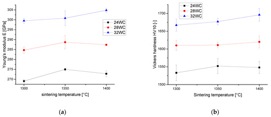
Figure 1.
(a) Young’s modulus of TZP-WC composites depending on tungsten carbide volume fraction and sintering temperature. (b) Vickers hardness HV10 of TZP-WC composites depending on tungsten carbide volume fraction and sintering temperature.
Figure 2a shows the bending strength σ4pt of TZP-WC composites depending on sintering temperature and tungsten carbide content. It can be observed that the strength the composites irrespective of tungsten carbide shows a similar trend to rise with sintering temperature. While materials sintered at 1300 °C show strength levels of 1000–1100 MPa, the materials sintered at 1400 °C may reach values of >1700 MPa for the highest WC content. The scattering of strength in the range of typically ±200–250 MPa is considerable. As Figure 2b shows that the fracture resistance of 6.3–6.6 MPa√m is very similar for all sintering temperatures, with even higher toughness values for low sintering temperatures. A temperature of 1400 °C seems to be required to efficiently eliminate defects.
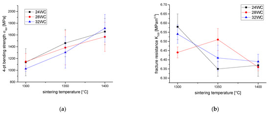
Figure 2.
(a) 4-point bending strength σ4pt of TZP-WC composites depending on tungsten carbide volume fraction and sintering temperature. (b) Fracture resistance KISB of TZP-WC composites depending on tungsten carbide volume fraction and sintering temperature.
3.2. Microstructure
Figure 3a,b show SEM images of thermally etched surfaces of 28 WC materials sintered at 1300 °C and 1400 °C. The crack running diagonally from bottom right to top left was induced by a HV10 indentation prior to etching.
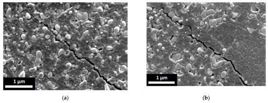
Figure 3.
SEM images of thermally etched (1100 °C/1 min H2) TZP-WC composites and crack tip induced by Vickers HV10 indentation. (a) Microstructure of 28 WC-1300. (b) Microstructure of 28 WC-1400. Bright phase strongly attacked by hydrogen etching corresponds to tungsten carbide and dark matrix phase with grain boundaries revealed corresponds to zirconia.
Evidently, the hydrogen etching process carried out to reveal the grain boundaries of the TZP matrix (dark phase) strongly attacks the tungsten carbide dispersion (bright phase). The phase contrast probably arises due to the influence of different amounts of backscattered electrons inducing secondary electrons. Higher sintering temperature does not affect the grain size of the tungsten carbide dispersion but results in grain growth in the matrix. At 1300 °C, the average grain size of zirconia is in the range between 100 nm and 150 nm while at 1400 °C grain growth to values of 250–400 nm is detectable. The indentation induced crack seems to be efficiently deflected at TZP-WC interfaces and WC grains are never fractured. In the TZP matrix, transgranular fracture prevails.
3.3. Phase Composition
Figure 4a shows the monoclinic content of TZP-WC composites in polished surfaces and in fracture surfaces. Standard errors were left out for sake of clarity, 2σ values are in the range of 0.15–0.25% for polished surfaces and 2–3% for fracture surfaces. Monoclinic zirconia fractions in the polished samples were in the range between 2 and 2.5 vol.% for materials sintered at 1300°C. Composites sintered at 1400°C had slightly lower monoclinic contents of 1.7–2%. The fracture surfaces of TZP-WC sintered at 1300 °C showed only variations of monoclinic content in the range of standard deviations, while the materials sintered at 1400 °C showed slight but significantly higher monoclinic contents at higher WC contents. Figure 4b shows that the transformation zone sizes h are very moderate (1–1.4 µm) and the resulting estimated transformation toughness values ΔKICT are in the range between 1.7 and 2.4 MPa√m. It should, however, be noted that transformation toughness values always increase with sintering temperature, which contrasts to the fracture resistance measurements that show an adverse trend in absolute toughness.
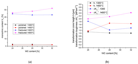
Figure 4.
Monoclinic contents calculated from X-Ray diffraction data and calculated transformation characteristics. (a) Monoclinic contents of polished surfaces and fracture faces of TZP-WC materials sintered at 1300 °C and 1400 °C. (b) Calculated transformation zone height h and transformation toughness increment ΔKICT.
3.4. Electrical Conductivity and Electric Discharge Machining
Figure 5 shows the electrical conductivity κ of TZP-WC composites and the major influence on conductivity is the tungsten carbide content. Conductivity rises non-linearly from 6.5 kS/m for 24 WC to 32 kS/m for 28 WC and exceeds 70 kS/m for 32 WC. A second but minor effect is visible: Higher sintering temperature favor higher conductivity. In this WC-percentage range, plotting κ vs. WC-content would show an exponential rise of conductivity with tungsten carbide content for all sintering temperatures.
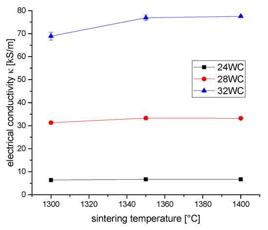
Figure 5.
Electrical conductivity κ of TZP-WC composites depending on composition and sintering temperature.
Literature values of electrical conductivity are 1.8 ∙ 104 kS/m for pure tungsten and 1.8 ∙ 103 kS/m for pure WC [24,25]. Table 3 shows the observed surface roughness and the measured material removal rates. As expected from the more moderate discharge energies in parameter set EDM 2, the material removal rates are four times lower. The surface roughness, however, is not reduced in the same ratio. The reason for this can be deduced from the structure of surfaces resulting from EDM tests using the two different parameters shown in Figure 6.

Table 3.
Surface roughness Ra, maximum Profile valley depth Rt and material removal rates MRR of ED-machined 28 WC-1400 for the two studied EDM parameter sets (see Table 2).
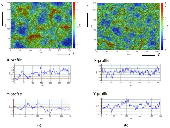
Figure 6.
White light interferometry images of ED-machined surfaces of 28 WC-1400. (a) 28 WC-1400 machined with parameter set EDM 1. (b) 28 WC-1400 machined with parameter set EDM 2. Upper images show topography in areas of 235 × 315 mm² size. Different colors indicate different height levels (see axis right). Profiles below show the topography along the X-axis and Y-axis.
The surface structure of an ED-machined material results from an overlay of a multitude of electrical discharges. Figure 6a,b show white light interferometry images of the surface of machined parts. The X-profiles and Y-profiles show the topography over the length of the images in both directions. Surfaces machined with parameter set 1 show a maximum profile depth of Rt~10 µm from the blue regions representing the center of the discharge craters to the red rims of the craters. In case of the EDM parameter set 2 which operates at a much lower discharge energy, the maximum profile depth is reduced to 8 µm.
Figure 7 shows SEM images of the machined surfaces. The dashed circles indicate the size of the discharge craters. For the high energy parameter set EDM 1, the craters have an approximate diameter of ~80 µm while for the low energy parameter set the craters have a size of only ~40 µm. The machined surface is very smooth and seems to consist of a very thin apparently glassy layer. The material removal mechanism is, therefore, dominated by melting processes. The size of small entrapped gas bubbles also scales with discharge energy. The surface of the EDM 1 sample shows a pronounced crack network dividing the surface into slabs of ~25 µm size (indicated as irregularly shaped areas in Figure 7a). Such cracks are apparently absent in the sample machined with parameter set EDM 2.
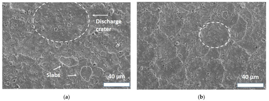
Figure 7.
SEM images of ED-machined surfaces of 28 WC-1400. Dashed circles indicate size of discharge craters and the dotted line encircles slabs created by surface crack network. (a) 28 WC-1400 machined with parameter set EDM 1. (b) 28 WC-1400 machined with parameter set EDM 2.
Figure 8a,b show the top view on machined surfaces in more detail. It becomes clear that a large part of the surface is covered with an extremely smooth surface layer but that there also exist some regions where this layer is spalled off (Figure 8a). The bulk material below is covered with a thin layer of machining debris, which is attached to the exposed surface. Figure 8b, which is taken at higher resolution, shows that the apparently glassy surface layer has a nanocrystalline structure. This is also supported by the crack structure which show a sawtooth structure that cannot be expected in a glassy material. Moreover, bubbles of 0.1–1 µm size are located within the surface layer. The larger ones are partly burst and the smaller ones were entrapped in the re-solidifying melt. At the bottom of burst bubbles, the bulk material covered with machining debris is visible.
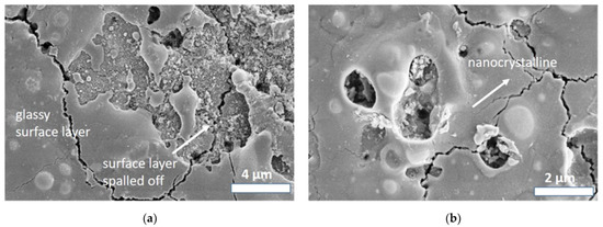
Figure 8.
Detail SEM images of ED-machined surfaces of 28 WC-1400. (a) 28 WC-1400 machined with parameter set EDM 1 showing a part of the sample covered by a smooth glass-like surface layer. (b) 28 WC-1400 machined with parameter set EDM 2, showing that the surface layer is not amorphous but nanocrystalline.
SEM-images of cross-cut polished sections reveal more details of the surface and subsurface structure. In the overview images, it becomes clear that the surfaces machined by parameter set EDM 1 are, in general, rougher. Cracks appear very often as multiple cracks, while for EDM 2 single cracks typically occur. The crack length (~7 µm) is very similar in both cases. The crack orientation is different and cracks in surfaces machined with EDM 1 are inclined, while in some cases even lateral cracks can be observed which may result in the spallation of surface fragments. In case of EDM 2, the cracks run more or less perpendicularly into the bulk. Surfaces are partly covered by a re-solidified layer with a thickness of approximately 1–1.5 µm. In this layer, the structure is different compared to the bulk material. Evidently, during melting, the finely dispersed phases coagulate and large globular WC grains embedded in re-solidified zirconia matrix are formed. The study of further SEM images shows that cracks very often originate in areas where the re-solidified layer is thicker and where larger WC grains are contained in the top layer.
A summary of mechanical, electrical properties and phase compositions of all investigated TZP-WC composites is contained in the Supplementary Material (Table S1).
4. Discussion
Hardness and especially the bending strength values indicate that increasing the sintering temperature to 1400 °C has a beneficial effect, while densities and Young’s modulus values seemed to indicate that 1300 °C is already sufficient to obtain well sintered materials. On the other hand, slightly decreasing toughness values with rising sintering temperature are not in line with the measured transformabilities of the zirconia matrix and the resulting transformation toughness. Some earlier studies on 3Y-TZP and YNd-TZP materials manufactured by powder coating technology can help clarify these discrepancies. In 3Y-TZP, it was found that the strength increases with sintering temperature while the toughness decreases [26]. This effect was explained in terms of elimination of an initial stabilizer gradient at higher sintering temperatures such that, despite a rise in grain size, a decrease in toughness was observed. It also seems that the extreme stabilizer supersaturated grain boundaries observed at low sintering temperatures in these materials seem less favorable in terms of strength compared to boundaries in co-precipitated or overfired stabilizer coated Y-TZP (with moderate super-saturation). In the case of YNd-TZP, the toughness and strength remain constant or are less unchanged over a larger sintering temperature range as the grain size and gradient effect seem to compensate and, due to the limited solubility of the neodymia in zirconia, the grains in 1.5Y1.5Nd-TZP retain a lower absolute stabilizer content compared to 3Y-TZP [17]. Ionic radii of the trivalent cations are 100.8 pm for ytterbium, 104 pm for yttrium, 109.8 for samarium and 112.3 pm for neodymium. The 1.5Yb1.5Sm-TZP mixed stabilizer system with a mean cation radius of 105.4 pm is closer to the 3Y-TZP system (104 pm) than to the 1.5Y1.5Nd-TZP system (108.2 pm) [27]. Thus, a reduction in toughness with sintering temperature and a concurrent increase in strength can be understood. The solubility limits of the stabilizer oxides (t/t+c phase boundary) according to Chen and Wang at sintering temperature (~1400 °C) are 2.5 mol% for Y2O3 and Yb2O3 but only 1 mol% for Sm2O3 and 0.8 mol% for Nd2O3 [17]. Phase diagrams for the mixed stabilizer systems are unavailable but it is very probable that the tetragonal phase in 1.5Yb1.5Sm-TZP contains slightly less stabilizer than in 3Y-TZP, but more than in 1.5Y1.5Nd-TZP. The second phase WC has a very high Young’s modulus, which results in a higher elastic constraint and a reduced transformability of the tetragonal grains [28]. This fact and, of course, the reduced zirconia content in the composites (see Equation (3)) have been identified for the lower toughness of YNd-TZP-WC composites compared to plain TZP. Transformation toughness values were calculated assuming a transformation efficiency X = 0.27 (predominantly dilatational), as in case of standard 3Y-TZP [29]. However, in an earlier publication, it has been speculated that TZPs retaining a stabilizer gradient (such sintered at lower temperature) might have a somewhat higher transformation efficiency due to the untransformable shell, which requires separate triggering of the transformation in each grain [30]. Such an effect would explain the discrepancies of toughness and calculated transformation toughness. Due to the fine grain size of the WC dispersion, other toughening effects such as crack deflection by residual stress fields (these increments are negative due to the lower CTE of WC compared to zirconia) and crack deflection at WC grains are negligible [31,32].
Changes in stabilizer also cause some indirect effects which might slightly alter the ED-machinability. Compared to TZP-WC composites with coprecipitated 3Y-TZP, the matrix grain size is reduced while the dispersion is unaffected. The electrical conductivity of YbSm-TZP-WC is reduced compared to a 3Y-TZP based composite of identical composition and sintering parameters (3Y-28WC-1400: κ = 72 kS/m [23]), most probably due to different resistivity in the matrix and due to the higher grain boundary volume in the ultrafine composite. The basic correlations are, however, unchanged. Both zirconia and WC have very high melting points (2680 °C for ZrO2 [33] and 2800 °C for WC [34]) and even higher evaporation temperatures (4300 °C for ZrO2 [33] and 6000 °C for WC [34]). The heat generated by the electric discharges is definitely sufficient to melt the material, but it is insufficient to completely evaporate it. The material removal is therefore dominated by melting of the matrix phase. Droplets of matrix phase will also result in the removal of dispersed WC. Small bubbles entrapped into the surface layer hint at certain contribution by evaporation/sublimation. In detail, the interpretation of the material removal mechanism is complicated by the fact that WC does not melt congruently. At 2993 K, a peritectic reaction takes place and hexagonal δ-WC transforms to cubic γ-WC, which at 3058 K decomposes and forms a liquid and free carbon. As in addition to WC, zirconia is present (which acts as an oxidant) and W2C (melting point 3058 K) is formed [35]. It is well known that this reaction already takes place at ~1500 °C and above [9]. Carbon may either be oxidized forming carbon monoxide (which may explain the gas bubbles) or even included in the anion sub-lattice of zirconia. Some re-solidified globular grains of WC in the re-solidified zirconia surface layer (or a material with similar appearance in SEM images) seem to confirm the existence of a liquid tungsten carbide phase.
The tendency to form a re-solidified layer and the absence of splashing at the boundaries of the discharge hints at the high viscosity of the melt. The thin re-solidified layer provides a smooth surface. However, the contraction during the phase change from liquid to solid may also account for the formation of cracks. As the residual stress around particles increases with R³/r³ (R = particle radius and r = distance from particle center) [36], the coagulation of small WC grains to larger globular grains also increases the level of residual stress in the re-solidified layer considerably and may act as another driving force for the formation of cracks originating from the surface. The fact that cracks are slightly inclined and not oriented perpendicular to the surface may be explained by the fact that the re-solidified top layer is under tension, which promotes formation of cracks. For stress neutrality the volume below is under compression, which results in a progressive crack deflection with increasing crack growth into the bulk.
As the machined surface is very hot, the toughness of the material at ambient temperature does not come into effect under machining conditions due to a lack of driving force for the t-m transformation at high temperatures [37]. An estimation of the strength reduction caused by the machining induced flaws with a size ac according to linear elastic facture mechanics (see Equation (5)) with geometry factor Y~2/π was carried out. The solution of (5) s for σ (with measured KIC values) results in approximated strength values of ~1700 MPa for 5 µm deep surface flaws, as seen in Figure 9 and ~850 MPa for 20 µm size flaws [38]. The equation is described as follows.
ac = KIC2/(π∙Y∙σ2)
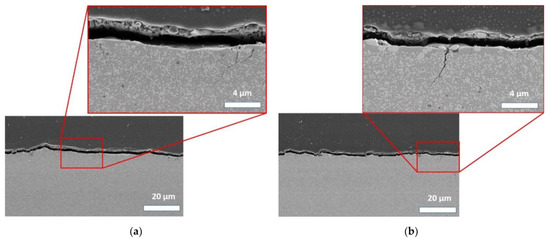
Figure 9.
SEM images of cross-cut and polished sections through ED-machined surfaces of 28 WC-1400. Red box: detailed images of cracked regions. (a) 28 WC-1400 machined with parameter set EDM 1. (b) 28 WC-1400 machined with parameter set EDM 2.
Small cracks as shown in Figure 9 would therefore not result in a significant reduction in strength (see Figure 2a). A comparison with strength data for ED-machined bending bars published by Olivier, which are in the range of 900–1150 MPa but based on tougher (KIC = 7–9 MPa√m) wire-cut 1.5Y1.5Nd-TZP-WC composites, results in the assumption that ED-induced critical flaw sizes of 20 µm seem realistic [39].
5. Summary and Conclusions
For the first time, ED-machinable TZP-WC ceramics with a mixed ytterbia-samaria stabilizer system were successfully manufactured by hot pressing. Highest strength, hardness and electrical conductivity values were observed at the highest tungsten carbide content and the highest sintering temperature of 1400 °C. Electric discharge machinability was confirmed for the 28 WC-1400 composite. The dominating material removal mechanism is melting; a thin very smooth re-solidified layer with a mean roughness of Ra ~1 µm forms on the surface. ED-machining results in cracks and these cracks have a uniform length of ~4–5 µm, but are formed more frequently under high energy machining conditions. Machining rates of ~1 mm³/min are acceptable for smaller complex shaped components. More detailed machining studies on modern ED-machines including the technologically important wire cutting processes are necessary to be able to fully evaluate the potential of the material in mechanical engineering.
Supplementary Materials
The following are available online at https://www.mdpi.com/article/10.3390/ceramics4030030/s1, Table S1: Mechanical and electrical properties and phase composition of TZP-WC materials.
Author Contributions
Conceptualization, A.G. and F.K.; methodology, A.G.; investigation, M.R.; data curation, M.R. and A.G.; writing—original draft preparation, F.K.; writing—review and editing, F.K.; visualization, M.R. and F.K.; supervision, F.K.; project administration, A.G. and F.K.; funding acquisition, F.K. All authors have read and agreed to the published version of the manuscript.
Funding
The study was funded by Deutsche Forschungsgemeinschaft (DFG) under grant number KE879/3-3.
Institutional Review Board Statement
Not applicable.
Informed Consent Statement
Not applicable.
Data Availability Statement
Data is contained within the Supplementary Materials to the article.
Acknowledgments
W.S. and F.P. are gratefully acknowledged for the SEM-Images.
Conflicts of Interest
The authors declare no conflict of interest. The funders had no role in the design of the study; in the collection, analyses or interpretation of data; in the writing of the manuscript or in the decision to publish the results.
References
- Gadow, R.; Kern, F. Chapter 2.06: Manufacturing of hard ceramics. In Comprehensive Hard Materials, 1st ed.; Sarin, V., Ed.; Elsevier: Amsterdam, The Netherlands, 2014; Volume 2, pp. 207–230. [Google Scholar]
- Halloran, J.W. Ceramic stereolithography: Additive manufacturing for ceramics by photopolymerization. Annu. Rev. Mater. Res. 2016, 46, 19–40. [Google Scholar] [CrossRef]
- Fu, X.; Zou, B.; Xing, H.; Li, L.; Li, Y.; Wang, X. Effect of printing strategies on forming accuracy and mechanical properties of ZrO2 parts fabricated by SLA technology. Ceram. Int. 2019, 45, 17630–17637. [Google Scholar] [CrossRef]
- Klocke, F.; König, W. Fertigungsverfahren 3, 4th ed.; Springer: Berlin, Germany, 2007; pp. 154–196. [Google Scholar]
- König, W.; Dauw, D.F.; Levy, G.; Panten, U. EDM-future steps towards the machining of ceramics. CIRP Ann. Manuf. Technol. 1988, 37, 3–126. [Google Scholar] [CrossRef]
- Wang, C.C.; Akbar, S.A.; Chen, W.; Patton, V.D. Review electrical properties of high-temperature oxides, borides, carbides and nitrides. J. Mater. Sci. 1995, 30, 1627–1641. [Google Scholar] [CrossRef]
- Alekseev, E.S.; Arkhipov, R.G.; Popova, S.V. Band structure of hexagonal tungsten carbide. Phys. Stat. Sol. B 1982, 110, K151–K154. [Google Scholar] [CrossRef]
- Pedzich, Z.; Haberko, K.; Piekarczyk, J.; Faryna, M.; Litynska, L. Zirconia matrix–tungsten carbide particulate composites manufactured by hot-pressing technique. Mater. Lett. 1998, 36, 70–75. [Google Scholar] [CrossRef]
- Haberko, K.; Pedzich, Z.; Dutkiewicz, J.; Faryna, M.; Kowal, A. Microstructure of the particulate system in the (Y)TZP WC system. In Ceramic Microstructure: Control at the Atomic Level; Tomsia, A.P., Glaeser, A., Eds.; Plenum Press: New York, NY, USA, 1998; pp. 741–748. [Google Scholar]
- Bonny, K.; De Baets, P.; Vleugels, J.; Salehi, A.; Van der Biest, O.; Lauwers, B. EDM machinability and frictional behavior of ZrO2-WC composites. Int. J. Adv. Manuf. Technol. 2009, 41, 1085–1093. [Google Scholar] [CrossRef]
- Anné, G.; Put, S.; Vanmeensel, K.; Jiang, D.; Vleugels, J.; Van der Biest, O. Hard, tough and strong ZrO2–WC composites from nanosized powders. J. Eur. Ceram. Soc. 2005, 25, 55–63. [Google Scholar] [CrossRef]
- Vleugels, J.; Xu, T.; Huang, S.; Kan, Y.; Wang, P.; Li, L.; Van der Biest, O. Characterization of (Nd,Y)-TZP ceramics prepared by a colloidal suspension coating technique. J. Eur. Ceram. Soc. 2007, 27, 1339–1343. [Google Scholar] [CrossRef]
- Xu, T.; Vleugels, J.; Van der Biest, O.; Wang, P. Mechanical properties of Nd2O3/Y2O3-coated zirconia ceramics. J. Mat. Sci. Eng. A 2004, 374, 239–243. [Google Scholar] [CrossRef]
- Kern, F. Ytterbia–neodymia–costabilized TZP—Breaking the limits of strength–toughness correlations for zirconia? J. Eur. Ceram. Soc. 2013, 33, 965–973. [Google Scholar] [CrossRef]
- Kern, F. Gadolinia-neodymia-co-stabilized zirconia materials with high toughness and strength. J. Ceram. Sci. Technol. 2012, 3, 119–130. [Google Scholar]
- Salehi, S.; Van der Biest, O.; Vleugels, J. Y2O3 and Nd2O3 co-stabilized ZrO2-WC composites. J. Mater. Sci. 2008, 43, 5784–5789. [Google Scholar] [CrossRef]
- Wang, C.; Zinkevich, M.; Aldinger, F. Phase diagrams and thermodynamics of rare-earth-doped zirconia ceramics. Pure Appl. Chem. 2007, 79, 1731–1753. [Google Scholar] [CrossRef]
- Chantikul, P.; Anstis, G.R.; Lawn, B.R.; Marshall, D.B. A critical evaluation of indentation techniques for measuring fracture toughness: II, strength method. J. Am. Ceram. Soc. 1981, 64, 539–543. [Google Scholar] [CrossRef]
- Mendelson, M.I. Average grain size in polycrystalline ceramics. J. Am. Ceram. Soc. 1969, 56, 443–446. [Google Scholar] [CrossRef]
- Toraya, H.; Yoshimura, M.; Somiya, S. Calibration curve for quantitative analysis of the monoclinic-tetragonal ZrO2 system by X-ray diffraction. J. Am. Ceram. Soc. 1984, 67, C119–C121. [Google Scholar]
- Kosmac, T.; Wagner, R.; Claussen, N. X-ray determination of transformation depths in ceramics containing tetragonal ZrO2. J. Am. Ceram. Soc. 1981, 64, C72–C73. [Google Scholar] [CrossRef]
- McMeeking, R.M.; Evans, A.G. Mechanics of transformation-toughening in brittle materials. Am. Ceram. Soc. 1982, 65, 242–246. [Google Scholar] [CrossRef]
- Gommeringer, A.; Schmitt-Radloff, U.; Ninz, P.; Kern, F.; Klocke, F.; Schneider, S.; Holsten, M.; Klink, A. ED-machinable ceramics with oxide matrix: Influence of particle size and volume fraction of the electrical conductive phase on the mechanical and electrical properties and the EDM characteristics. Procedia CIRP 2018, 68, 22–27. [Google Scholar] [CrossRef]
- MATWEB-Database. Available online: http://www.matweb.com/search/DataSheet.aspx?MatGUID=41e0851d2f3c417ba69ea0188fa570e3 (accessed on 14 June 2021).
- MATWEB-Database. Available online: http://www.matweb.com/search/datasheet.aspx?matguid=e68b647b86104478a32012cbbd5ad3ea&n=1 (accessed on 14 June 2021).
- Kern, F.; Strumberger, H.; Gadow, R. Effects of stabilizer content and sintering conditions on Y-TZP ceramics made from stabilizer coated nanopowders. J. Ceram. Sci. Techn. 2017, 9, 7–18. [Google Scholar]
- Shannon, R.D. Revised effective ionic radii and systematic studies of interatomic distances in halides and chalcogenides. Acta Crystallogr. Sect. A 1976, 32, 751–767. [Google Scholar] [CrossRef]
- Lange, F.F. Transformation toughening—Part 1. Size effects associated with the thermodynamics of constrained transformations. J. Mater. Sci. 1982, 17, 225–234. [Google Scholar] [CrossRef]
- Swain, M.V.; Rose, L.R.F. Strength limitations in transformation-toughened zirconia alloys. J. Am. Ceram. Soc. 1986, 69, 511–518. [Google Scholar] [CrossRef]
- Kern, F. Evidence of phase transitions and their role in the transient behavior of mechanical properties and low temperature degradation of 3Y-TZP made from stabilizer-coated powder. Ceramics 2019, 2, 271–285. [Google Scholar] [CrossRef] [Green Version]
- Taya, M.; Hayashi, S.; Kobayashi, A.S.; Yoon, H.S. Toughening of a particulate-reinforced ceramic-matrix composite by thermal residual stress. J. Am. Ceram. Soc. 1990, 73, 1382–1391. [Google Scholar] [CrossRef]
- Becher, P.F. Microstructural design of toughened ceramics. J. Am. Ceram. Soc. 1991, 74, 255–269. [Google Scholar] [CrossRef]
- GESTIS Stoffdatenbank. Zirconium (IV) Oxide. Available online: https://gestis.dguv.de/data?name=004000&lang=en (accessed on 16 March 2021).
- GESTIS Stoffdatenbank. Tungsten Carbide. Available online: https://gestis.dguv.de/data?name=491085&lang=en (accessed on 16 March 2021).
- Kurlov, A.S.; Gusev, A.I. Tungsten carbides and WC phase diagram. Inorg. Mater. 2006, 42, 121–127. [Google Scholar] [CrossRef]
- Kingery, W.D.; Bowen, H.K.; Uhlmann, D.R. Introduction to Ceramics, 1st ed.; Wiley and Sons: New York, NY, USA, 1976; p. 785. [Google Scholar]
- Kelly, P.M.; Rose, L.R.F. The martensitic transformation in ceramics—Its role in transformation toughening. Prog. Mat. Sci. Eng. 2002, 47, 463–557. [Google Scholar] [CrossRef]
- Anglada, M. Assessment of mechanical properties of ceramic materials. In Advances in Ceramic Biomaterials; Palmero, P., Cambier, F., De Barra, E., Eds.; Woodhead Publishing: Duxford, UK, 2017; pp. 83–109. [Google Scholar]
- Olivier, M.; Heß, R.; Gommeringer, A.; Kern, F.; Herrig, T.; Bergs, T. Wire electrical discharge machinability and load-bearing capacity of ATZ-WC composite ceramics. In Proceedings of the 24th International Conference on Material Forming (ESAFORM 2021), Liège, Belgium, 14–16 April 2021; Available online: http://dx.doi.org/10.25518/esaform21.4032. (accessed on 7 July 2021).
Publisher’s Note: MDPI stays neutral with regard to jurisdictional claims in published maps and institutional affiliations. |
© 2021 by the authors. Licensee MDPI, Basel, Switzerland. This article is an open access article distributed under the terms and conditions of the Creative Commons Attribution (CC BY) license (https://creativecommons.org/licenses/by/4.0/).