Article

Fracture Toughness Evaluation and Plastic Behavior Law of a Single Crystal Silicon Carbide by Nanoindentation

1
Department of Mechanical Engineering and Materials Science, Yale University, New Haven, CT 06511, USA
2
Department of Chemical Engineering, Yale University, New Haven, CT 06511, USA
3
Ceramic Science and Technology Division, Oak Ridge National Laboratory, Oak Ridge, TN 37831, USA
4
Guangdong University of Technology, Guangzhou 510090, China
*
Author to whom correspondence should be addressed.
Ceramics 2018, 1(1), 198-210; https://doi.org/10.3390/ceramics1010017
Submission received: 10 July 2018 / Revised: 6 September 2018 / Accepted: 6 September 2018 / Published: 18 September 2018

Abstract

:
Nanoindentation-based fracture toughness measurements of ceramic materials like silicon carbide (SiC) with pyramidal indenters are of significant interest in materials research. A majority of currently used fracture toughness models have been developed for Vickers indenters and are limited to specific crack geometries. The validity of the indentation-cracking method for the fracture toughness measurement of single crystal SiC, the elastic-plastic anisotropy and orientation dependence around the c-axis when indented in the <0001> direction is examined using nanoindentation with different pyramidal indenters. The residual impressions are analyzed using scanning electron microscopy to measure the crack lengths and the validity of existing fracture toughness measurement methods and equations is analyzed. A combination of nanoindentation with different pyramidal indenters to produce a wide range of effective strains and finite element simulation is used to extract flow properties of single crystal SiC in the <0001> direction. It is observed that there is no orientation dependence around the c-axis when SiC-6H is indented in the <0001> direction with a Berkovich indenter, i.e., it is transversely isotropic. It is also found that for a Berkovich indenter, the Jang and Pharr model, which is based on the Lawn model for cone/halfpenny cracks, gives approximately constant values at low loads (<1 N), while at higher loads (>1 N), the Laugier model gives constant fracture toughness values. Finite element analysis using equivalent cones is used along with measured hardness values to estimate the yield strength, the work hardening exponents and the stress–strain curve for single crystal SiC-6H in the <0001> direction.

1. Introduction

1.1. Silicon Carbide

Silicon carbide (SiC) as a material for structural applications has received tremendous interest starting in the 1980s for high temperature, high stress applications like gas turbine engines to increase their efficiency and life span. SiC crystallizes in over 200 polytypes [1,2] with different Si–C stacking sequences. The most common polytypes are the 3C (Cubic) or β and 6H (Hexagonal) or α-SiC [3] and have similar mechanical and thermal properties but different electrical and optical properties. SiC, due to covalent bonding, has a high elastic modulus (~450 GPa) and has shear yield strength of about one tenth of the shear modulus [4], which makes it suitable for composite armor and high strength applications. SiC has superior creep behavior and wear resistance [5,6] which make it an ideal material for use in wear resistant coatings in a variety of automotive components like pistons, valve heads, bearings, etc. and in micro-electromechanical systems. The physical (wide bandgap, high thermal conductivity and high electric field strength) and chemical properties of SiC-6H polytype make it an ideal material for high temperature, high frequency, high power devices, including radar and microwave applications under extreme conditions [7].
Nanoindentation, although initially developed for probing mechanical properties of thin films [8,9,10,11,12] and small-length scale properties [13,14], has recently emerged as an important technique and has been used for high and low temperature testing [15], high strain rate testing [16], dynamic testing for storage and loss moduli [17], creep testing [18,19] and testing properties in a variety of environments (liquids, etc.) [20].
SiC has a high resistance to yielding, but unlike metals, cracks and pre-existing flaws easily propagate because there is very limited dislocation-mediated plastic deformation. A few researchers have attempted to investigate the fracture strength of single crystal SiC-6H using microspecimens [21,22,23,24]. Henshall et al. [24] found that the fracture toughness of single crystal SiC-6H is 3.3 MPa·m1/2 using 3-point bend specimens, which are aligned such that the notch was in the (11–20) plane and the direction of crack propagation is <1–100>. Liang et al. [25] measured the fracture toughness of polycrystalline SiC and compared it to single edge-notched beam (SENB) measurements and found the fracture toughness to be around 3 MPa·m1/2. Sharpe et al. [21,22] found the fracture strength of single crystal SiC-6H microspecimens to be 0.5–1.5 GPa in tension, when the tensile axis is orientated parallel to the <10–10> direction. Nihara et al. [26] and Swayer et al. [27] also performed Knoop hardness measurements on the (0001), (10–10) and (11–20) planes and concluded that the primary-slip system in SiC-6H on which plastic deformation under indentation occurs is preferentially (0001) <11–20> at low temperatures and (1010) <11–20> at high temperatures. Henshall et al. [28] in 1985 used a combination of Vickers and Berkovich indentation in SiC-6H on the (0001) and the (1–100) planes along with SENB measurements to determine the anisotropy of the fracture toughness and hardness. Miyoshi et al. [29] showed that friction, deformation, and fracture of the SiC (0001) surface depend on the crystallographic orientation and that the anisotropies are primarily controlled by the slip system (10–10) <11–20> and cleavages of (10–10) and (0001). Qian et al. [30] measured the Knoop and Vickers hardness and fracture toughness of SiC-6H single crystals and observed that the values at the asymptotic-hardness region are significantly smaller (~20%) than those at low loads, indicating an indentation size-effect. In order to study inelastic deformation mechanisms in SiC-6H, Page et al. [4,31] performed TEM measurements of the deformation zones beneath the indenter and found that plastic deformation is accommodated entirely by nucleation and outward propagation of dislocations on the basal plane, which points to the importance of dislocation-mediated plasticity during indentation of SiC-6H. Kitahara et al. [32] concluded that the primary cleavage planes both in SiC-6H are less resistant to fracture in some cases during indentation experiments which means cleavage of single crystals is an important factor in addition to grain boundary failure in the assessment of cracking in polycrystals. Another study by Yan et al. [33] showed evidence that Berkovich indentation of single crystal SiC-6H transforms the single crystal into polycrystalline SiC directly under the indenter tip. In addition to forming microcracks and basal plane dislocations around the indent, it was also found that the depth of indentation-induced subsurface damage is greater than the indentation depth based on TEM observations. Recent studies on elastic and plastic anisotropy by indentation experiments have shown that SiC has very weak anisotropy in modulus and hardness in different orientations studied [34]. The location of the indent and the stress states during loading are therefore necessary to determine which mode controls the deformation or cracking.

1.2. Fracture Toughness Measurement Using Nanoindentation

Nanoindentation has proved to be a useful tool to evaluate the fracture toughness (mode I) of materials based on the formation of cracks at the corners during indentation. The lengths of cracks, which extend due to the residual stress field, can be related to the fracture toughness of the material. Lawn and Evans [35] proposed the use of Vickers indentation for fracture toughness measurement in the 1980s to relate the plane-strain, mode I, critical stress intensity factor (KIC) to the observed crack lengths. The Lawn equation (Equation (1) below) is based on Hill’s expanding cavity solution for an elastic-plastic solid assuming a halfpenny crack:
K I C = α ( E H ) 1 / 2 ( P c 3 / 2 )  
where P is the indentation load, E is Young’s modulus, H is the hardness, c is the total length from the center of the indent to the end of crack and α is a constant related to the crack morphology and the shape of the indenter used. From the expressions proposed by different researchers over the last two decades, those proposed by Anstis [36], who fitted Equation (1) using experimental data for brittle materials over a range of KIC (1 to 12 MPa·m1/2), and Laugier [37] who modified Equation (1) according to specifics of the crack geometry, have been the most commonly used. Pharr and Jang [38] suggested a modification to the parameter α (α = (0.03352/(1 − ν))(Cot(ψ))2/3) in the Lawn model, to take into account the half-opening angle (ψ) of different pyramidal indenters, and the poisson’s ratio of the material (ν). The Pharr and Jang model [38] was found to be valid for cone/halfpenny cracks. Gong et al. [39] also suggested a modification for the Anstis equation to include the indentation size effect at low loads. The Laugier equation (Equation (2) which was developed for determining the fracture toughness of WC-Co (Tungsten Carbide–Cobalt) ceramics for Palmquist cracks using a Vickers indenter, is given by:
K I C = χ v ( l a ) 1 / 2 ( E H ) 2 / 3 ( P c 3 / 2 )  
where l is the length of the length of the crack; a is the length from the center of the indent to the corner of the indent; E, H, P and c have the same meanings as in Equation (1); and χv was found to be 0.015 for radial cracks [37]. Dukino and Swain in 1992 [40] developed a correction to the Laugier equation (χv = 0.016) for a Berkovich indenter by taking into account the number of symmetric cracks proposed by Ouchterlony. Conventional indentation cracking methods for fracture toughness measurement require a long crack larger than the indent size. In ceramics, the indent size is comparable to the equilibrium crack size [35,36]. The role of plasticity is difficult to evaluate in hard ceramics, which gives a more qualitative measure of the toughness when measured using indentation cracking methods [38].

1.3. Estimation of Flow Properties Using Nanoindentation Experiments

Extraction of (stress, strain) flow properties using the values of hardness and modulus obtained during nanoindentation experiments relies on the calculation of constraint factors and characteristic strains for a given geometrically self-similar indenter and an assumed constitutive relationship. A unique solution can be obtained using pyramidal indenters with different centerline-to-face angles combined with finite element analysis. Various researchers have used nanoindentation data to obtain stress–strain curves for a material. The method used by Shim et al. [41] is used to estimate the stress–strain curve. The finite element procedure, which is based on Tabor’s concepts of characteristic strains and constraint factors, starts with an initial guess of the yield strength (Y). It is assumed that the materials have a linear elastic response up to the yield point, and follow the Hollomon stress–strain law with the constraint factor relating hardness to flow stress, and that the conical finite element simulations used approximates the behavior of the three-sided pyramid indenters used in experiments. Since it is not possible to get information about plasticity in ceramics using uniaxial testing at room temperatures, nanoindentation with different centerline-to-face angle indenters can be used to extract information about the plasticity of these ceramics. The constraint on deformation due to the indentation geometry produces plastic deformation in these materials, even though they are very brittle in conventional tension or compression tests.
The nanoindentation fracture toughness measurement using pyramidal indenters remains a topic of significant interest, especially for ceramics and other brittle materials. A majority of indentation fracture toughness models are based on the measurements done using the top view of the impression, and it is assumed that cracks created during indentation are halfpenny or Palmquist cracks. The cracking mode during indentation can change depending on the load and the half-opening angle of the indenter used. This research is aimed at studying the validity of the popular indentation fracture toughness models over a range of loads for pyramidal indenters with different half-opening angles. This research also uses a combination of nanoindentation results with different pyramidal results (different characteristic strains) and finite element simulations to generate stress–strain curves and obtain plasticity information about SiC-6H, which cannot be obtained by traditional tension-compression testing at room temperature.

2. Materials and Methods

A Nanoindenter XP® (Nano Instruments Innovation Center, MTS Corporation, Knoxville, TN, USA) was used to perform nanoindentation experiments at ambient temperature using Berkovich [42] and pyramidal indenters with different centerline-to-face angles on the single crystal SiC samples used in this research. All nanoindentation experiments were done using the continuous stiffness measurement (CSM) technique [43] which gives the load on the sample and the contact stiffness as a function of the displacement of the indenter into the samples. The single crystal samples (semiconductor-grade Cree Research, Inc., Durham, NC, USA—herein after referred to as SiC-6H) used in this study were electronic-grade α-SiC (6H polytype). The crystal was transparent with a greenish color from the N impurity with EPI(Epitaxy ready)-grade-polished Si-face. The single crystal wafer was broken along the cleavage planes in the <a> direction and then mounted in resin. Polishing of the mounted samples was done by first mechanical polishing with SiC grit paper from 120 to 2400 grit followed by polishing with Buehler MasterMet 2 non-crystallizing colloidal silica (SiO2) polishing suspension (0.02 µm) using a vibratory polisher. The SiC-6H (Cree single crystal SiC) samples were indented using pyramidal indenters with different half-opening angles (ψ) of the indenter (45°, 55°, 65.3°, 75°), perpendicular to the (0001) and the (−12–10) plane. Data were taken as an average of more than 20 indents. Scanning electron microscopy (SEM) analysis was conducted using a Zeiss Auriga dual beam FIB/SEM instrument to image the post indentation residual impressions made by different indenters on various samples. A Nikon interference microscope was also used to characterize the amount of pile-up post indentation in single crystal samples. Indentation when performed in the <0001> direction is herein after indicated as SiC-6H(0001).
A commercial finite element package ABAQUS was used to perform two-dimensional finite element analysis (FEA) using an axis-symmetric model (a cylinder with 200 µm in both length and radius) of four-node linear axisymmetric elements with rigid conical indenters with half-included angles 52.1°, 61.4°, 70.3° and 78.2°, corresponding to half-opening angles of 45°, 55°, 65.3° and 75°, respectively, of the pyramidal indenters. The method outlined by Shim et al. [44] shown schematically in Figure S2 in Supplementary Materials, was used to perform FEA simulations to estimate the flow properties of SiC-6H in the <0001> direction. The friction coefficients of 0 and 0.2 were chosen to represent the ideal frictionless case and the realistic case for SiC-6H, respectively.

3. Results and Discussion

3.1. Berkovich Indentation on SiC-6H Single Crystal

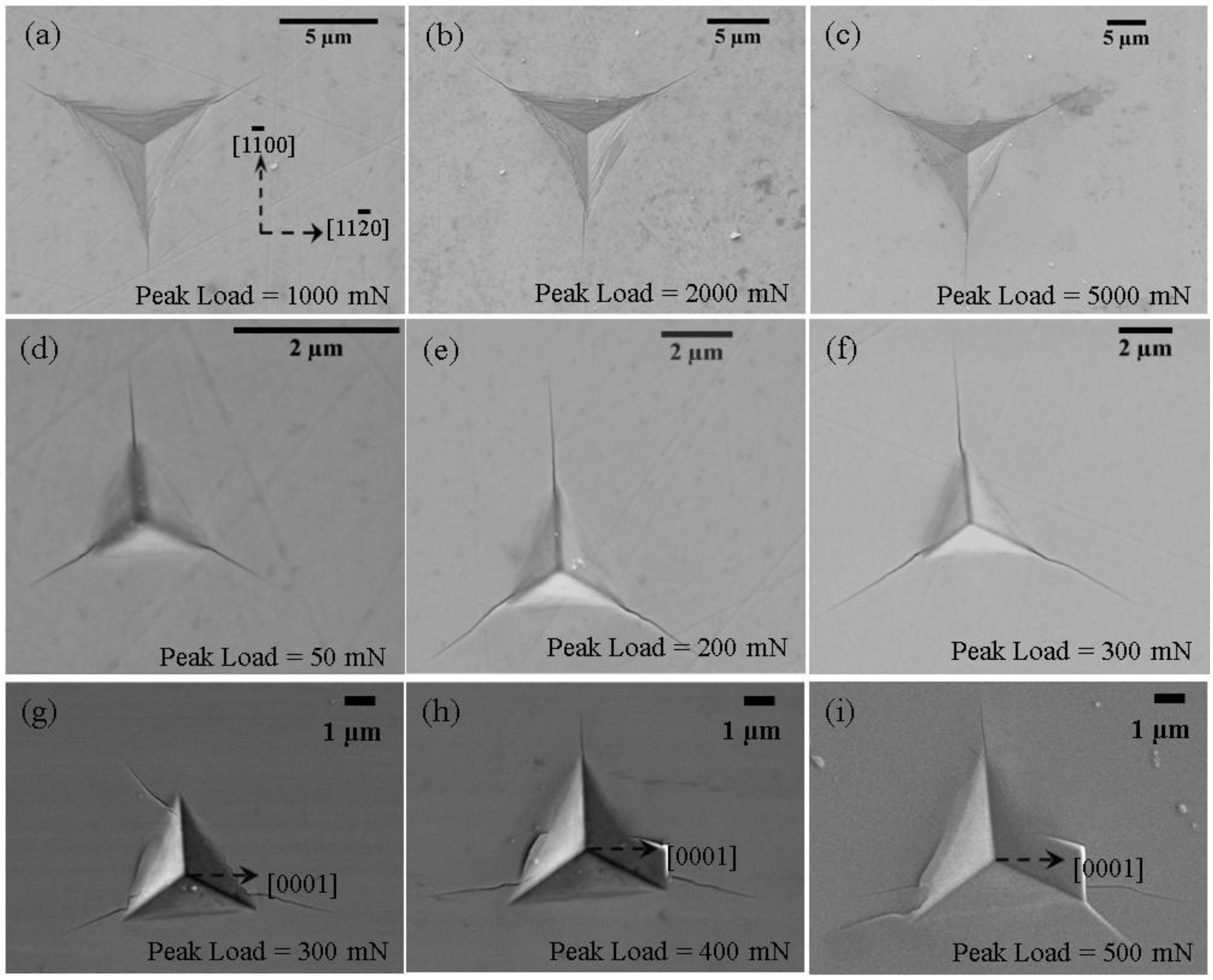
Figure 1 below shows the load (P) vs. displacement into surface (h), modulus (E) vs. h and hardness (H) vs. h curves for SiC-6H single crystal samples. The hardness and the modulus data were corrected for pile-up behavior by using SEM and interference microscope images of the indents to determine the actual contact area. It can be seen from Figure 1c that the SiC-6H when indented in the <0001> direction shows an indentation size effect on the hardness. This is probably due to pop-in behavior at low loads observed during the Berkovich indentation experiments on SiC-6H samples when indented in the <0001> direction (see Supplementary Materials, Figure S1). SiC-6H when indented in the <01–10> direction does not show any pop-in behavior during Berkovich indentation (see Supplementary Materials, Figure S1). The results are summarized in Table 1 below. The hardness and modulus of SiC-6H in the <0001> direction is higher than in the <01–10> direction. The differences in modulus and hardness between the <0001> and the <01–10> directions are ~7% and <0.5%, respectively, indicating that SiC-6H has very little elastic and plastic anisotropy. The hardness values are similar to those obtained in previous research by Shaffer et al. [45], who obtained a hardness of around 30 GPa in the c-axis and around 26 GPa in the a-axis using a Knoop indenter, and by Henshall et al. [28] who obtained hardness values of around 30 GPa in the <0001> and 28 GPa in the <1–100> direction using a Berkovich indenter. Figure 2 shows representative SEM images of Berkovich indentations in SiC-6H single crystal samples when indented in the <0001> and the <01–10> directions. A difference in the cracking pattern between the two orientations is observed; when indented in the <0001> direction, cracks originate at the tip (Figure 2a–f), whereas for <01–10> (Figure 2g–i), at least one out of three or sometimes all of the cracks originate from the side of the indent for reasons related to anisotropy in cleavage cracking. Based on our previous research [34] and conclusions made by other researchers on elastic and plastic anisotropy in SiC-6H [4,31,45,46], indentation in the <0001> direction is primarily used to determine cracking behavior and flow properties.

3.2. Indentation Cracking in SiC-6H

3.2.1. Orientation Effects in SiC-6H Single Crystals during Indentation in the <0001> Direction

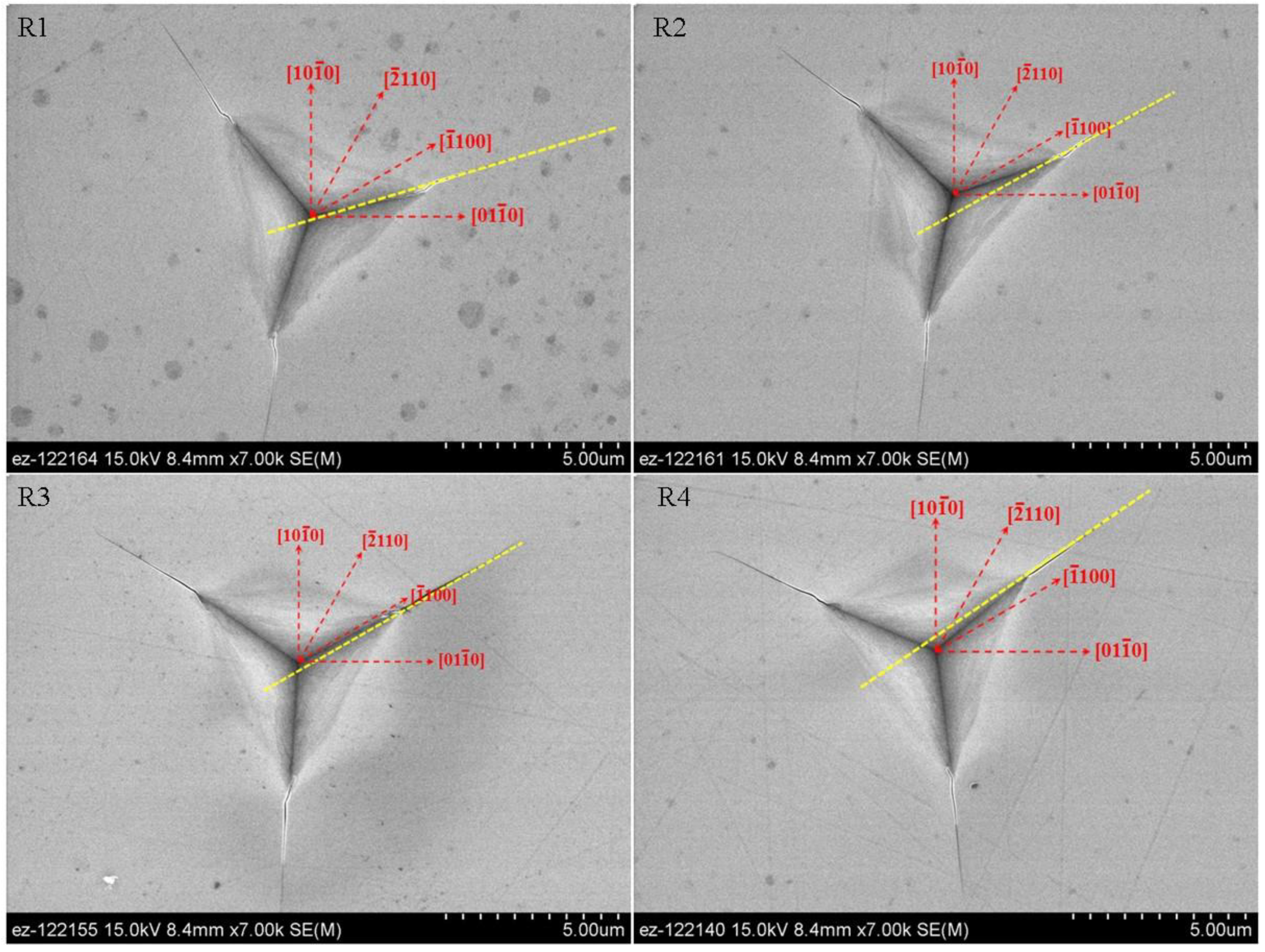
The SiC-6H single crystal samples were indented with a Berkovich indenter in the <0001> direction by rotating them in the <a> plane to study indenter orientation effects. Figure 3 shows representative images in four different rotations around the <0001> axis in the <a> plane. The yellow lines in the images show the path of the cracks. It can be seen from the images that the crack propagation in the single crystal generally takes place parallel to the nearest cleavage plane. There is very little difference (<1% between the maximum and the minimum) in the measured hardness, modulus and the crack lengths in these indentation experiments, indicating that SiC-6H does not exhibit significant orientation effects during Berkovich indentation experiments in the <0001> direction. Table 2 shows the average hardness, modulus, and c/a ratios for different rotation angles. These observations agree with observations made by Shaffer et al. [45], who also noticed that there is no significant difference in the hardness values when using the Knoop indenter in the <0001> axis with the long axis of the indenter parallel to the (10–10) and (11–20) faces.

3.2.2. Influence of Indenter Angle (Centerline-to-Face) on Cracking in SiC-6H(0001)

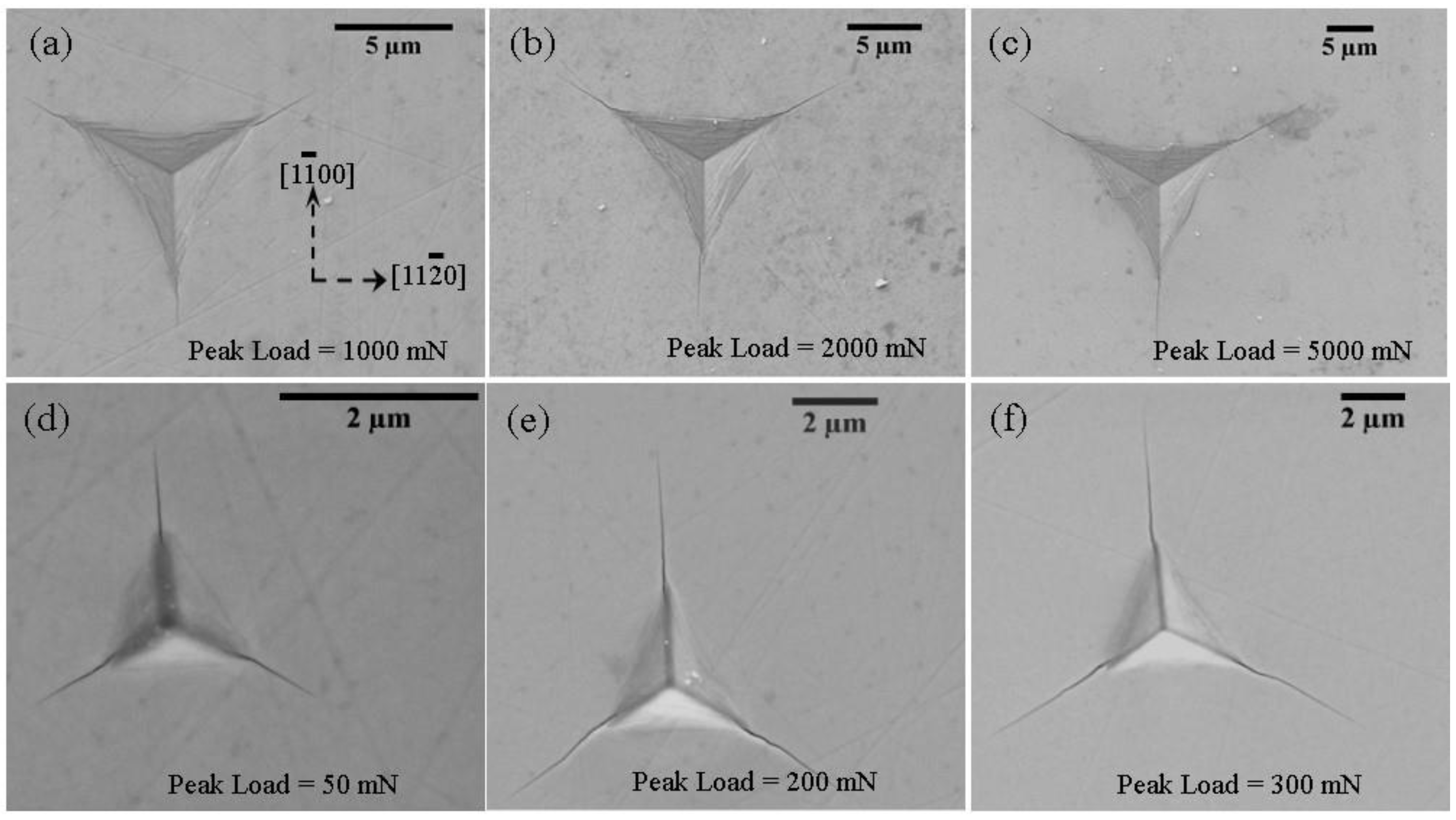
Pyramidal tips with different centerline-to-face angles were used to study the effect of the indenter angle on the cracking of SiC-6H when indented in the <0001> direction. Figure 4a–c shows representative SEM images of indents using a 75° pyramidal indenter at different peak loads on SiC-6H in the <0001> direction. Figure 4d–f shows representative SEM images of indentations in SiC-6H in the <0001> direction using a 55° pyramidal indenter at various peak loads. The sharper the indenter, the more strain it will generate in a material for a given peak load. A 55° pyramidal indenter therefore has a greater displacement into surface than a 75° indenter at a particular peak load. At low loads, for brittle ceramics, previous literature has shown that, it is expected that there will be median radial cracking at low loads, which Palmquist cracking will be at higher loads. Previous research [19,38] has shown that a sharper indenter, which induces more strain in the material, may be able to change the cracking mode from the median radial cracking mode to the Palmquist cracking mode. It can be seen from Figure 2, Figure 3 and Figure 4 that the surface cracking patterns for all the 55°, 65° and 75° pyramidal indenters appear to be similar. However, there might be a difference in the subsurface cracking between the sharper (55°) and the blunter (75°) indenters. It can also be seen from SEM images that at a particular peak load, the crack lengths for a shaper indenter are much larger than those for a blunt indenter.

3.3. Fracture Toughness Measurement in SiC-6H(0001)

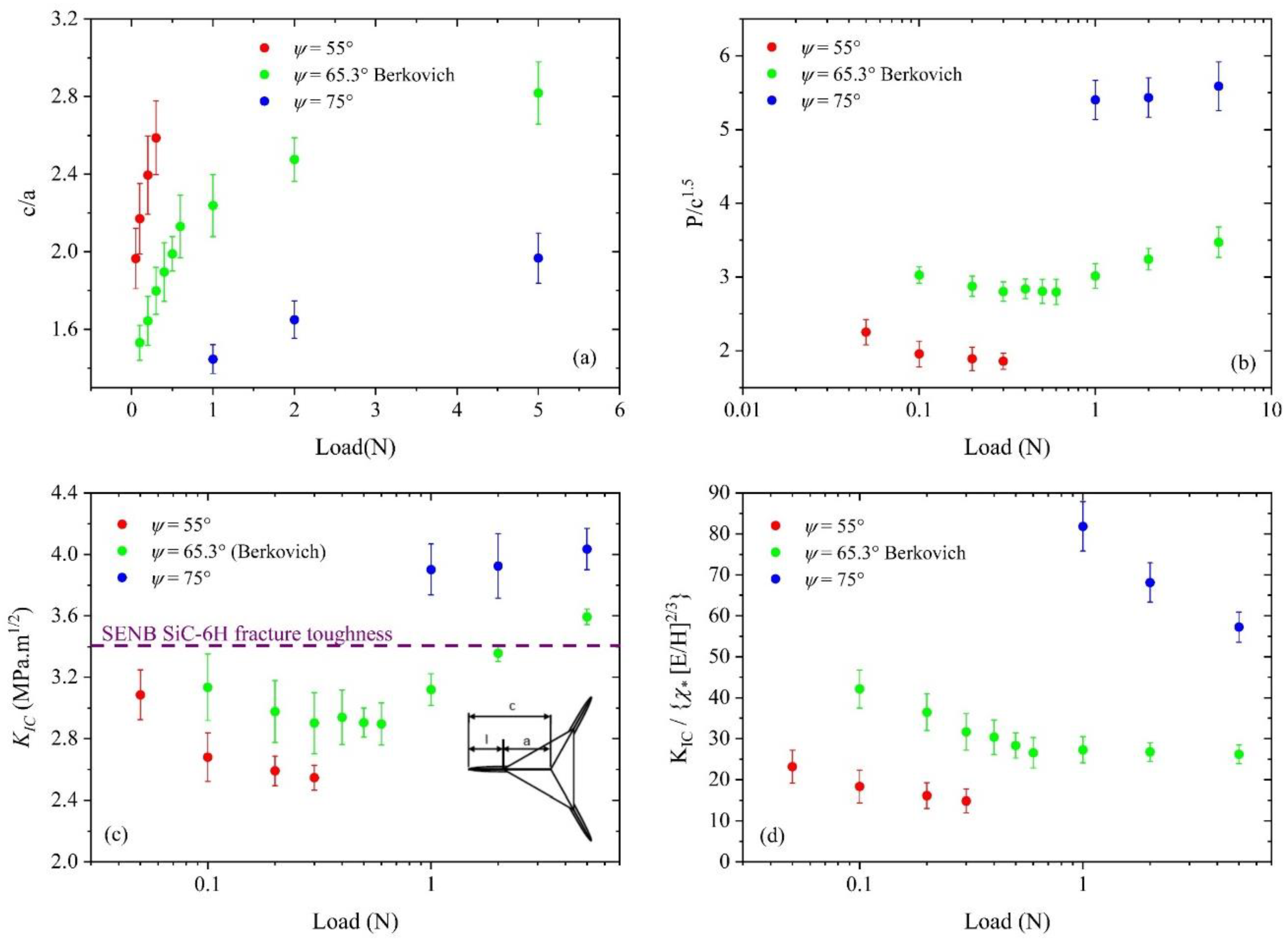
Figure 5a,b shows the variation of c/a and the P/c1.5 ratios at various loads (P) for different pyramidal indenters when the SiC-6H single crystal samples are indented in the <0001> direction. The results show that the c/a ratios are not constant, indicating that the cracking behavior of the SiC-6H when indented in the <0001> direction is not geometrically self-similar. According to the model developed by Lawn et al. [35] and the model developed by Jang and Pharr [38], the P/c1.5 ratio should stay constant for a given material, provided that there is no change in the cracking mode. It can be seen from Figure 5b that the ratio stays approximately constant for the Berkovich indenter up to 1 N peak load, after which it starts increasing. This might be indicative of a change from the median cracking to the Palmquist cracking regime. Figure 5c shows the indentation fracture toughness of SiC-6H(0001) at various peak loads evaluated using both the Lawn and the Laugier models. The Lawn model gives constant values up to 1 N loads, after which the Laugier model gives constant values. Since the Lawn model and the Laugier model were developed for median and Palmquist cracking systems, respectively, it is conceivable that at low loads (<1 N), the cracking is median radial-type while at higher loads (>1 N), the cracking is of Palmquist type. The observed indentation fracture toughness is about 3.2 MPa·m1/2. Liang et al. [25] also obtained similar values of approximately 3 MPa·m1/2 for polycrystalline SiC using indentation methods that are verified using SENB experiments.
Applying the Laugier and the Jang and Pharr models (based on the Lawn model) for fracture toughness measurements with pyramidal indenters with different centerline-to-face angles requires accurate constants. Since the equations were developed for certain crack morphologies, in order to check whether the fracture toughness equations are valid for a given indenter over a range of loads, the Jang and Pharr equation and the Laugier equation can be modified to Equations (3) and (4), respectively:
K I C / α ( E H ) 1 / 2 = ( P c 3 / 2 ) = constant  
K I C / χ v ( E H ) 2 / 3 = ( l a ) 1 / 2 ( P c 3 / 2 ) = constant  
where in the Equations (3) and (4) above, the left side of the modified equation above should be constant for a given indenter geometry and a given material; KIC, α, χ, E and H are constant as long as there are no indentation size effects or changes in the mode of fracture. Figure 5c,d shows the evaluation of the validity of the Laugier model and the Jang and Pharr model based on the Lawn model for the fracture toughness measurement in SiC-6H when indented in the <0001> direction. It can be seen from Figure 5c,d that the Laugier model does not yield constant values for the modified equation at low loads for a 55° centerline-to-face angle indenter as compared to the Jang and Pharr model based on the Lawn model, while for a 75° centerline-to-face angle indenter, the Jang and Pharr model based on the Lawn model is valid for peak loads up to 5 N. The Laugier model does not seem to yield constant values up to 5 N peak load for a 75° pyramidal indenter. It is conceivable that at higher loads for a 75° indenter, the Laugier model might give constant values for fracture toughness.

3.4. Extraction of Flow Properties

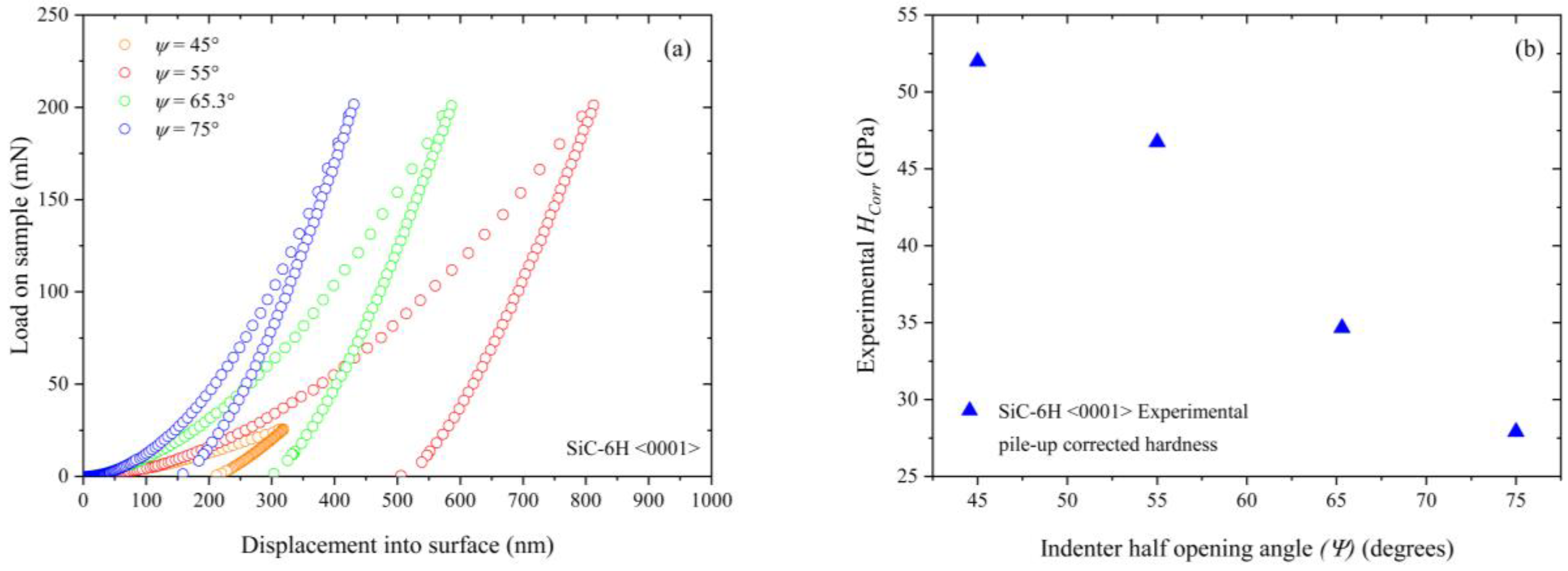
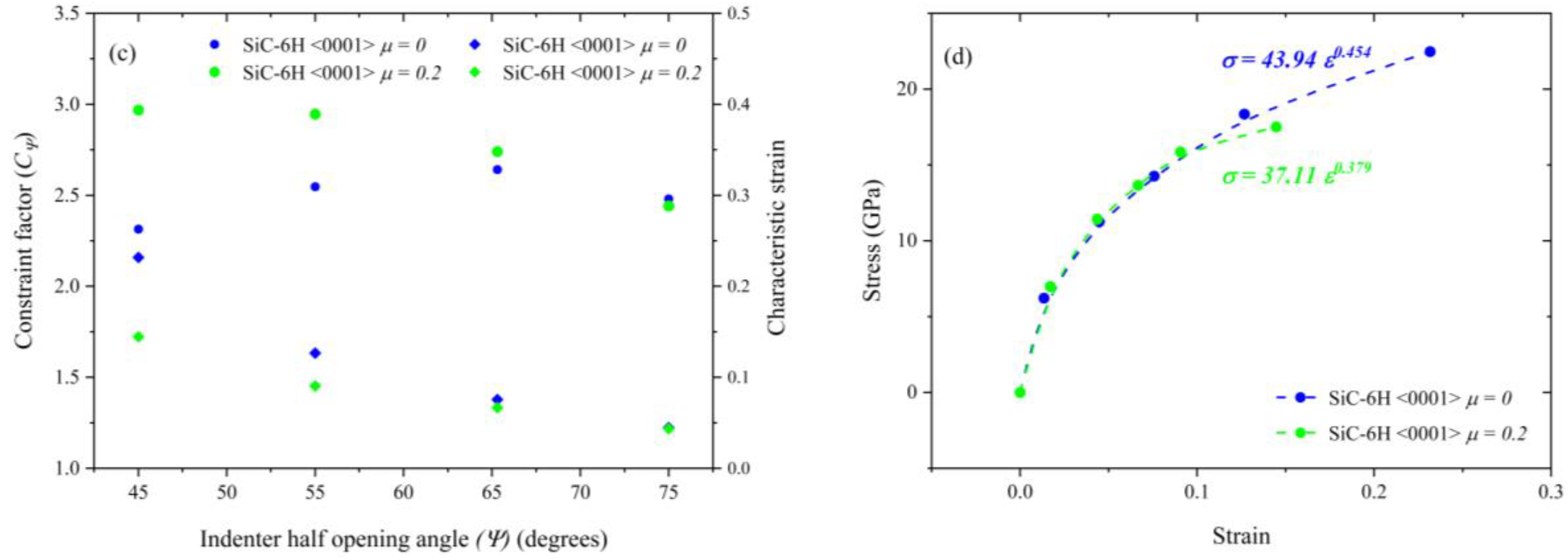
Nanoindentation experiments with pyramidal indenters having different centerline-to-face angles were performed on SiC-6H along the <0001> direction. Figure 6a,b shows the load displacement curves with different pyramidal indenters at peak loads of 200 mN, and the hardness values measured using the residual impressions. As expected, the penetration depth and therefore the hardness decreases with an increase in the centerline-to-face angle, while an increase in reversible elastic recovery is also observed with an increasing centerline-to-face angle. Since the FEA analysis requires accurate values of modulus, the value obtained using the elastic contact prediction of 460 GPa for the elastic modulus in the <0001> direction [34] is used in the analysis. The elastic modulus (460 GPa), pile-up-corrected hardness (Hcorr) (Figure 6b) for different pyramidal indenters, a poisson’s ratio of 0.18, an assumed friction coefficient (0 or 0.2) and an initial guess of yield strength (Y = Hcorr/2) are the starting inputs for the iterative process (see Supplementary Materials, Figure S2). Figure 6c,d summarizes the FEA results for the characteristic strains, constraint factors and flow stresses after 4 iterations for different half-opening indenter angles (ψ = 45°, 55°, 65°, 75°) and friction coefficients (µ = 0 and 0.2). It should be noted that friction plays an important role in calculating the hardness of a material and in determining the constraint factor and characteristic strains for sharp indenters. According to the literature [41], the normal force exerted by an indenter can increase by up to 20% for a 45° indenter with an increase in the friction coefficient from 0 to 0.2. Based on the constraint factors and characteristic strains and the E/Y ratios obtained in the FEA analysis, the Hollomon fit variables (n and K) are calculated and shown in Figure 6. Figure 6d shows the stress–strain curves for SiC-6H(0001) extracted using the flow stress and characteristic strain values obtained from a combination of experimental indentation hardness values and FEA simulations using equivalent cones. The results from the FEA analysis shown in Figure 6d show similar trends to the results obtained by Shim et al. [44] but the values of the Holloman fit exponents (n and K) and the yield strength are different due to the difference in the values of the modulus and hardness used by Shim et al. [44]. The yield strength is estimated to be 6.2–8 GPa, which agrees with previous literature [4,41].

4. Conclusions

Nanoindentation experiments were carried out to experimentally evaluate the fracture and plastic flow of single crystal SiC in the <0001> direction. Salient observations include:
  • There is no significant indenter orientation dependence when indented in the <0001> direction using a Berkovich indenter, indicating that SiC-6H is a transversely isotropic material.
  • It was found as expected that the sharper indenters produce more strains in the material and longer cracks for a given peak load. The surface cracking patterns are similar for all pyramidal indenters used in this research. This does not consider any subsurface cracking that might occur due to different pyramidal indenters. It is also possible that there might be lateral subsurface cracking at higher loads along with possible phase transformation in the material at higher loads for a particular indenter. Further careful study of the subsurface cracking needs to be done for a better understanding of the effects of cracking on fracture toughness.
  • Fracture toughness measurements were carried out, and the Jang and Pharr model based on the Lawn model and the Laugier models were evaluated for different pyramidal indenters. It was found that within the range of our testing loads, the Jang and Pharr model for the fracture toughness measurement works better for estimating the fracture toughness of SiC-6H in the <0001> direction. It was also found that for a Berkovich indenter, the Lawn model, which is for medial radial cracking modes, gives approximately constant values at low loads (<1 N). It was also found that for a Berkovich indentation experiments in SiC-6H in the <0001> direction, at higher loads (>1 N), the Laugier model gives constant fracture toughness values. It is conceivable that there is a change in the cracking modes in this range of loads. Since most indentation fracture toughness models are developed using assumptions based on the top view of residual impressions, it becomes apparent based on the experimental results that careful consideration and attention must be given to possible changes in cracking, phase transitions and other mechanisms with increasing loads along with the indenter geometry.
  • Finite element analysis using equivalent cones was used along with measured hardness values to estimate the yield strength, the work hardening exponents and the stress–strain curve for single crystal SiC-6H in the <0001> direction. It was found that it is possible to estimate the stress–strain curve, the yield strength of a material and the Holloman fit constants for a brittle material like SiC-6H, provided accurate information about friction coefficients is available. Verification of the stress–strain curve is not possible due to the non-availability of room temperature uniaxial stress–strain curves. The results obtained in this study show good agreement with previous researchers.

Supplementary Materials

The following are available online at https://www.mdpi.com/2571-6131/1/1/17/s1.

Author Contributions

A.D. conceived, conducted and analyzed the experiments. All authors collaborated to compose the manuscript.

Acknowledgments

This research was supported by the US National Science Foundation CMMI 0926798.

Conflicts of Interest

The authors declare no conflict of interest.

References

  1. Fisher, G.R.; Barnes, P. Towards a unified view of polytypism in silicon carbide. Philos. Mag. Part B 1990, 61, 217–236. [Google Scholar] [CrossRef]
  2. Bechstedt, F.; Käckell, P.; Zywietz, A.; Karch, K.; Adolph, B.; Tenelsen, K.; Furthmüller, J. Polytypism and Properties of Silicon Carbide. Phys. Status Solidi B 1997, 202, 35–62. [Google Scholar] [CrossRef]
  3. Shaffer, P. A review of the structure of silicon carbide. Acta Crystallogr. Sect. B 1969, 25, 477–488. [Google Scholar] [CrossRef] [Green Version]
  4. Page, T.F.; Oliver, W.C.; McHargue, C.J. The deformation behavior of ceramic crystals subjected to very low load (nano)indentations. J. Mater. Res. 1992, 7, 450–473. [Google Scholar] [CrossRef]
  5. Pierson, H.O. Handbook of Refractory Carbides & Nitrides; William Andrew: Norwich, NY, USA, 1996. [Google Scholar]
  6. Snead, L.L.; Nozawa, T.; Katoh, Y.; Byun, T.-S.; Kondo, S.; Petti, D.A. Handbook of SiC properties for fuel performance modeling. J. Nucl. Mater. 2007, 371, 329–377. [Google Scholar] [CrossRef]
  7. Powell, A.R.; Rowland, L.B. SiC materials-progress, status, and potential roadblocks. Proc. IEEE 2002, 90, 942–955. [Google Scholar] [CrossRef]
  8. Korsunsky, A.M.; McGurk, M.R.; Bull, S.J.; Page, T.F. On the hardness of coated systems. Surf. Coat. Technol. 1998, 99, 171–183. [Google Scholar] [CrossRef]
  9. Herbert, E.G.; Tenhaeff, W.E.; Dudney, N.J.; Pharr, G.M. Mechanical characterization of LiPON films using nanoindentation. Thin Solid Films 2011, 520, 413–418. [Google Scholar] [CrossRef]
  10. Borrero-López, O.; Hoffman, M.; Bendavid, A.; Martin, P.J. A simple nanoindentation-based methodology to assess the strength of brittle thin films. Acta Mater. 2008, 56, 1633–1641. [Google Scholar] [CrossRef]
  11. Hainsworth, S.V.; McGurk, M.R.; Page, T.F. The effect of coating cracking on the indentation response of thin hard-coated systems. Surf. Coat. Technol. 1998, 102, 97–107. [Google Scholar] [CrossRef]
  12. Nair, A.K.; Cordill, M.J.; Farkas, D.; Gerberich, W.W. Nanoindentation of thin films: Simulations and experiments. J. Mater. Res. 2009, 24, 1135–1141. [Google Scholar] [CrossRef] [Green Version]
  13. Nix, W.D.; Gao, H. Indentation size effects in crystalline materials: A law for strain gradient plasticity. J. Mech. Phys. Solids 1998, 46, 411–425. [Google Scholar] [CrossRef]
  14. Ma, Q.; Clarke, D.R. Size dependent hardness of silver single crystals. J. Mater. Res. 1995, 10, 853–863. [Google Scholar] [CrossRef]
  15. Beake, B.D.; Goodes, S.R.; Smith, J.F. Nanoscale materials testing under industrially relevant conditions: High-temperature nanoindentation testing. Z. Met. 2003, 94, 798–801. [Google Scholar] [CrossRef]
  16. Constantinides, G.; Tweedie, C.A.; Holbrook, D.M.; Barragan, P.; Smith, J.F.; van Vliet, K.J. Quantifying deformation and energy dissipation of polymeric surfaces under localized impact. Mater. Sci. Eng. A 2008, 489, 403–412. [Google Scholar] [CrossRef]
  17. Wright, W.J.; Nix, W.D. Storage and loss stiffnesses and moduli as determined by dynamic nanoindentation. J. Mater. Res. 2009, 24, 863–871. [Google Scholar] [CrossRef]
  18. Lucas, B.N.; Oliver, W.C. Indentation power-law creep of high-purity indium. Metall. Mater. Trans. A 1999, 30, 601–610. [Google Scholar] [CrossRef]
  19. Su, C.; Herbert, E.G.; Sohn, S.; LaManna, J.A.; Oliver, W.C.; Pharr, G.M. Measurement of power-law creep parameters by instrumented indentation methods. J. Mech. Phys. Solids 2013, 61, 517–536. [Google Scholar] [CrossRef]
  20. Mann, A.B.; Pethica, J.B. Nanoindentation Studies in a Liquid Environment. Langmuir 1996, 12, 4583–4586. [Google Scholar] [CrossRef]
  21. Sharpe, W.N.; Beheim, G.M.; Evans, L.J.; Nemeth, N.N.; Jadaan, O.M. Fracture Strength of Single-Crystal Silicon Carbide Microspecimens at 24 °C and 1000 °C. J. Microelectromech. Syst. 2008, 17, 244–254. [Google Scholar] [CrossRef]
  22. Sharpe, W.N., Jr.; Jadaan, O.; Beheim, G.M.; Quinn, G.D.; Nemeth, N.N. Fracture strength of silicon carbide microspecimens. J. Microelectromech. Syst. 2005, 14, 903–913. [Google Scholar] [CrossRef]
  23. Nakao, S.; Ando, T.; Chen, L.; Mehregany, M.; Sato, K. Mechanical characterization of SiC film at high temperatures by tensile test. In Proceedings of the 2008 IEEE 21st International Conference on Micro Electro Mechanical Systems, Wuhan, China, 13–17 January 2008; pp. 447–450. [Google Scholar]
  24. Henshall, J.L.; Rowcliffe, D.J.; Edington, J.W. Fracture Toughness of Single-Crystal Silicon Carbide. J. Am. Ceram. Soc. 1977, 60, 373–375. [Google Scholar] [CrossRef]
  25. Liang, K.M.; Orange, G.; Fantozzi, G. Evaluation by indentation of fracture toughness of ceramic materials. J. Mater. Sci. 1990, 25, 207–214. [Google Scholar] [CrossRef]
  26. Niihara, K. Slip systems and plastic deformation of silicon carbide single crystals at high temperatures. J. Less Common Met. 1979, 65, 155–166. [Google Scholar] [CrossRef]
  27. Sawyer, G.R.; Sargent, P.M.; Page, T.F. Microhardness anisotropy of silicon carbide. J. Mater. Sci. 1980, 15, 1001–1013. [Google Scholar] [CrossRef]
  28. Henshall, J.L.; Brookes, C.A. The Measurement of Kic in Single-Crystal Sic Using the Indentation Method. J. Mater. Sci. Lett. 1985, 4, 783–786. [Google Scholar] [CrossRef]
  29. Miyoshi, K.; Buckley, D.H. Friction and Deformation Behavior of Single-Crystal Silicon Carbide; NASA-TP-1053; NASA Lewis Research Center: Cleveland, OH, USA, 1977. [Google Scholar]
  30. Qian, J.; Daemen, L.L.; Zhao, Y. Hardness and fracture toughness of moissanite. Diam. Relat. Mater. 2005, 14, 1669–1672. [Google Scholar] [CrossRef]
  31. Page, T.F.; Riester, L.; Hainsworth, S.V. The Plasticity Response of 6H-Sic and Related Isostructural Materials to Nanoindentation: Slip vs Densification. MRS Online Proc. Libr. 1998, 522. [Google Scholar] [CrossRef]
  32. Kitahara, H.; Noda, Y.; Yoshida, F.; Nakashima, H.; Shinohara, N.; Abe, H. Mechanical behavior of single crystalline and polycrystalline silicon carbides evaluated by Vickers indentation. J. Ceram. Soc. Jpn. 2001, 109, 602–606. [Google Scholar] [CrossRef]
  33. Yan, J.; Gai, X.; Harada, H. Subsurface damage of single crystalline silicon carbide in nanoindentation tests. J. Nanosci. Nanotechnol. 2010, 10, 7808–7811. [Google Scholar] [CrossRef] [PubMed]
  34. Datye, A.; Li, L.; Zhang, W.; Wei, Y.J.; Gao, Y.F.; Pharr, G.M. Extraction of Anisotropic Mechanical Properties From Nanoindentation of SiC-6H Single Crystals. J. Appl. Mech. 2016, 83, 091003. [Google Scholar] [CrossRef] [Green Version]
  35. Lawn, B.R.; Evans, A.G.; Marshall, D.B. Elastic/Plastic Indentation Damage in Ceramics: The Median/Radial Crack System. J. Am. Ceram. Soc. 1980, 63, 574–581. [Google Scholar] [CrossRef]
  36. Anstis, G.R.; Chantikul, P.; Lawn, B.R.; Marshall, D.B. A Critical Evaluation of Indentation Techniques for Measuring Fracture Toughness: I, Direct Crack Measurements. J. Am. Ceram. Soc. 1981, 64, 533–538. [Google Scholar] [CrossRef]
  37. Laugier, M.T. Palmqvist indentation toughness in WC-Co composites. J. Mater. Sci. Lett. 1987, 6, 897–900. [Google Scholar] [CrossRef]
  38. Jang, J.-I.; Pharr, G.M. Influence of indenter angle on cracking in Si and Ge during nanoindentation. Acta Mater. 2008, 56, 4458–4469. [Google Scholar] [CrossRef]
  39. Gong, J.; Wang, J.; Guan, Z. Indentation toughness of ceramics: A modified approach. J. Mater. Sci. 2002, 37, 865–869. [Google Scholar] [CrossRef]
  40. Dukino, R.D.; Swain, M.V. Comparative Measurement of Indentation Fracture Toughness with Berkovich and Vickers Indenters. J. Am. Ceram. Soc. 1992, 75, 3299–3304. [Google Scholar] [CrossRef]
  41. Shim, S.; Jang, J.-I.; Pharr, G.M. Extraction of flow properties of single-crystal silicon carbide by nanoindentation and finite-element simulation. Acta Mater. 2008, 56, 3824–3832. [Google Scholar] [CrossRef]
  42. Berkovich, E.S. Three-faceted diamond pyramid for micro-hardness testing. Ind. Diam. Rev. 1951, 11, 129–133. [Google Scholar]
  43. Oliver, W.C.; Pharr, G.M. An improved technique for determining hardness and elastic modulus using load and displacement sensing indentation experiments. J. Mater. Res. 1992, 7, 1564–1583. [Google Scholar] [CrossRef]
  44. Shim, S.; Bei, H.; George, E.P.; Pharr, G.M. A different type of indentation size effect. Scr. Mater. 2008, 59, 1095–1098. [Google Scholar] [CrossRef]
  45. Shaffer, P.T.B. Effect of Crystal Orientation on Hardness of Silicon Carbide. J. Am. Ceram. Soc. 1964, 47, 466. [Google Scholar] [CrossRef]
  46. Li, C.; Zhang, F.H.; Meng, B.B.; Ma, Z.K. Simulation and Experiment on Surface Morphology and Mechanical Properties Response in Nano-Indentation of 6H-SiC. J. Mater. Eng. Perform. 2017, 26, 1000–1009. [Google Scholar] [CrossRef]
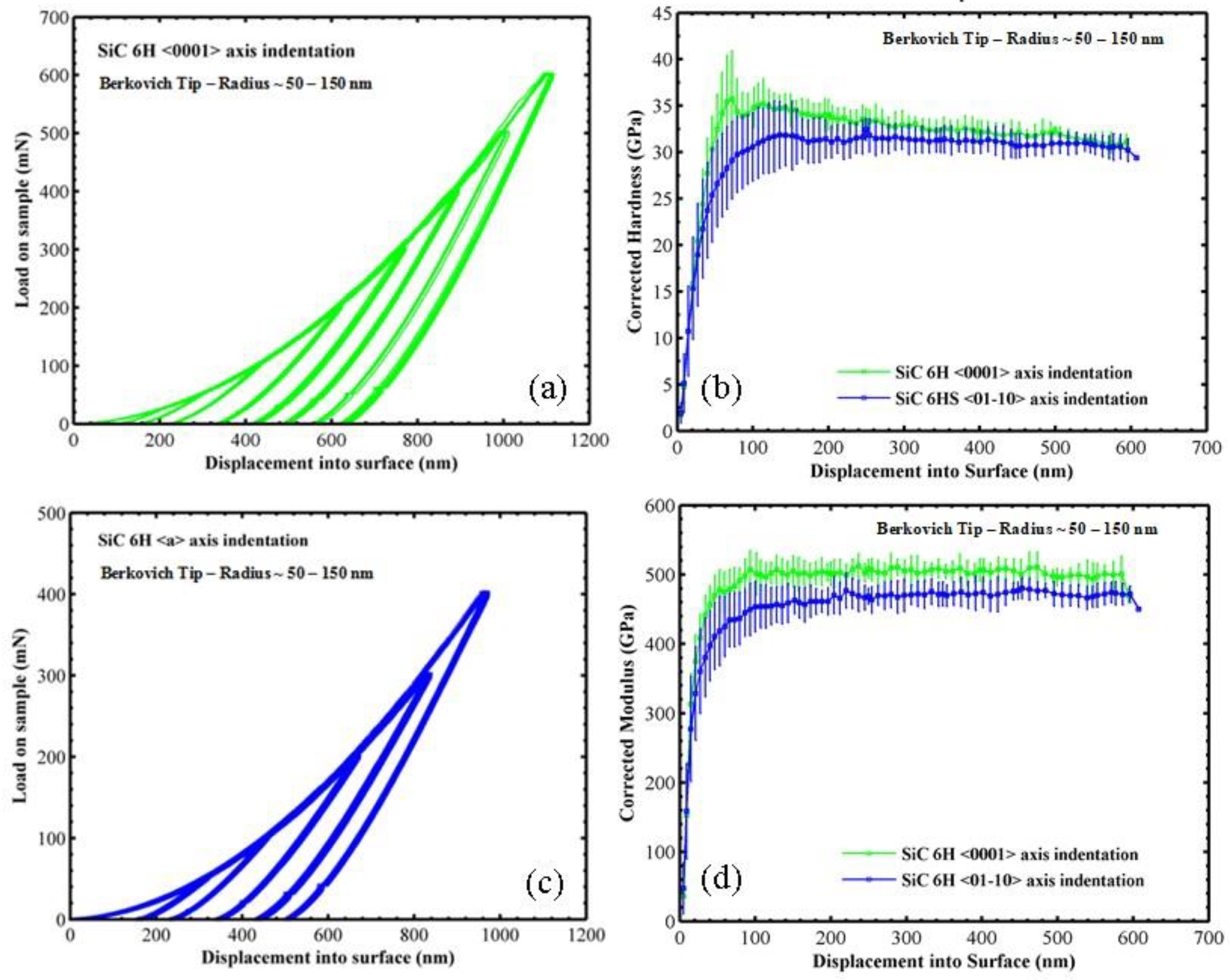
Figure 1. (a,c) Load–displacement curves for Berkovich indentation of SiC-6H samples. (b) Pile-up-corrected hardness (H)—displacement into surface (h) curves for Berkovich indentation of SiC-6H samples (d) Pile-up-corrected modulus (E)—h curves for Berkovich indentation of SiC-6H samples.
Ceramics 01 00017 g001
Figure 2. (af) Representative SEM images of Berkovich indentation of SiC-6H in the <0001> direction at different peak loads. (gi) Representative SEM images of Berkovich indentation of SiC-6H in the <01–10> direction at different peak loads.
Ceramics 01 00017 g002
Figure 3. Representative images of Berkovich indentations in SiC-6H in the <0001> direction with different rotations around the <0001> axis. (Yellow lines are drawn approximately on the crack or parallel to the crack to indicate the angle).
Ceramics 01 00017 g003
Figure 4. (ac) Representative SEM images of indentations with a 75° tip in SiC-6H in the <0001> direction at different peak loads, (df) representative SEM images of indentation with a 55° pyramidal tip in SiC-6H in the <0001> direction at different peak loads.
Ceramics 01 00017 g004
Figure 5. (a) Load (P) vs c/a ratio for indentation in SiC-6H(0001) with different pyramidal indenters. (b) Load vs. P/c1.5 ratio. (c) Fracture toughness measurement in SiC-6H(0001) using different pyramidal indenters based on the Jang and Pharr model. (d) Evaluation of the Laugier model based on Equation (4).
Ceramics 01 00017 g005
Figure 6. (a) Ph curves for indentation of SiC-6H in the <0001> direction with pyramidal indenters of different centerline-to-face angles. (b) Corrected hardness (input) measured as a peak load over a measured area (obtained with an SEM) for pyramidal indenters of different centerline-to-face angles. (c) Constraint factor (output) and characteristic strain (output) with pyramidal indenters of different centerline-to-face angles using FEA analysis. (d) Stress–strain curves for SiC-6H(0001) using FEA analysis.
Ceramics 01 00017 g006aCeramics 01 00017 g006b
Table 1. Modulus and hardness of SiC-6H measured by Berkovich indentation.
SiC-6H—Indentation DirectionBerkovich Indentation
EOPHOPECorrHCorr
(GPa)(GPa)(GPa)(GPa)
<0001>549.66 ± 20.6340.97 ± 1.21503.13 ± 28.1932.26 ± 5.01
<01-10>513.71 ± 19.8439.13 ± 0.79461.94 ± 22.4930.81 ± 2.1
Table 2. Hardness, modulus and c/a ratios for Berkovich indentation along the c–axis in different orientations around the c axis.
Ceramics 01 00017 i001EOPHOPc/a
(GPa)(GPa)@ 500 mN
R1 (θ ≈ 19°)543.81 ± 27.1349.70 ± 3.671.97 ± 0.06
R2 (θ ≈ 12°)546.58 ± 29.2949.64 ± 3.141.96 ± 0.09
R3 (θ ≈ 5°)545.64 ± 24.4649.08 ± 2.752.03 ± 0.07
R4 (θ ≈ 7°)542.77 ± 21.4448.85 ± 2.491.98 ± 0.13