Review

Recent Progress and Scientific Challenges in Wire-Arc Additive Manufacturing of Metallic Multi-Material Structures

1
Department of Engineering Technology, Kennesaw State University, Marietta, GA 30060, USA
2
Department of Mechanical Engineering, Cleveland State University, Cleveland, OH 44115, USA
3
Department of Nanoscience, Joint School of Nanoscience and Nanoengineering, University of North Carolina at Greensboro, Greensboro, NC 27401, USA
4
Vitzronextech Co., Ltd., Ansan 15603, Republic of Korea
5
Department of Engineering & Technology, Eastern Kentucky University, Richmond, KY 40475, USA
6
Department of Applied Engineering and Technology Management, Indiana State University, Terre Haute, IN 47809, USA
7
School of Environmental, Civil, Agricultural, and Mechanical Engineering, University of Georgia, Athens, GA 30602, USA
*
Author to whom correspondence should be addressed.
J. Manuf. Mater. Process. 2025, 9(8), 284; https://doi.org/10.3390/jmmp9080284
Submission received: 4 July 2025 / Revised: 5 August 2025 / Accepted: 13 August 2025 / Published: 21 August 2025

Abstract

Metallic multi-material structures are heterogeneous structures characterized by changing composition, microstructures, and site-specific characteristics, advantageous for numerous applications where multifunctionality is desired. Metallic multi-material structures are known as bimetallic structures (BSs), which are functionally graded materials (FGMs). In recent years, wire-arc additive manufacturing (WAAM) advanced as a promising additive manufacturing process to realize the fabrication of these structures due to its high deposition rate, cost-effectiveness, and material utilization efficiency. This review presents a comprehensive overview of the recent progress, processing strategies, and scientific challenges in WAAM of multi-material structures. The paper begins with an introduction to multi-material structures, followed by a bibliometric analysis of the current research landscape. Conventional and additive manufacturing fabrication approaches are presented. The review highlights key developments in processing strategies and critically evaluates research studies on WAAM of BS and FGMs. Major scientific challenges, including porosity, lack of fusion, residual stresses, cracking, material compatibility, and brittle intermetallic phase formation, are critically analyzed. Additionally, modeling, simulation, and process automation issues are discussed as barriers to industrial-scale implementation. The paper concludes with an outlook on future research directions to address existing challenges and accelerate the adoption of WAAM for complex multi-material components.

1. Introduction

1.1. Multi-Material Structures

In the pursuit of high-performance engineering solutions, modern industries increasingly demand materials that can meet complex and often conflicting performance criteria, such as high strength, low weight, corrosion resistance, and thermal stability. Traditional monolithic materials often fall short of delivering such multifunctionality, prompting a shift toward composite and hybrid material systems. One promising approach is the development of multi-material structures, which integrate two or more distinct materials within a single component to leverage their individual and combined advantages [1]. These structures are engineered to achieve specific functional characteristics that are challenging or impossible to realize with a single material [2]. For instance, combining a material with high strength and one with high toughness can result in a durable and impact-resistant structure, which is advantageous in various engineering applications [3]. Nature offers numerous examples of multi-material structures, which have evolved to optimize performance under diverse conditions. One prominent example is the human bone, a composite structure of hard hydroxyapatite and soft collagen [4]. Hydroxyapatite, providing rigidity, whereas the collagen contributes to the bone’s flexibility and toughness. Another example is the nacre (mother of pearl) found in mollusk shells. Nacre is composed of aragonite platelets interspersed with organic biopolymers, giving it exceptional toughness despite its brittle ceramic constituents [5]. These examples available in nature inspire the design of metallic multi-materials for aerospace, automotive, and medical applications.
Multi-material structures are widely used across various industries due to their ability to combine tailored properties, offering improved functionality and performance. For instance, IN718/316L multi-material structures can achieve high heat resistance and oxidation resistance to high temperatures as well as sufficient mechanical strength and toughness for low temperatures, thus providing presenting enormous promise in the aerospace industry [3]. In the automotive industry, multi-material structures of steel–aluminum are utilized in body panels and engine components to reduce weight improve fuel efficiency and sustainable transportation solution [6,7]. The medical sector benefits from multi-material structures in implants and surgical tools. Materials like CoCrMo alloys, Ti alloys, Nb and 316L stainless steel are chosen for their biocompatibility and corrosion resistance, ensuring safety and longevity in medical applications [8]. Consequently, multi-material structures can facilitate the manufacturing of end-use parts including unique designs and multi-material configurations, thereby meeting the escalating demands of the aerospace, biomedical, automobile, energy, defense, marine, and opto-electronics, and construction sectors [9,10,11,12,13,14,15,16].
Bimetallic structures (BS) and functionally graded materials (FGMs) are two most common metallic multi-material structures employed advanced engineering applications as depicted in Figure 1 [17]. While both aim to exploit the benefits of multiple materials, they differ significantly in terms of design philosophy, interface characteristics, and fabrication complexity. Understanding these distinctions is critical for selecting the appropriate approach based on performance requirements and manufacturing capabilities. As shown in Table 1, BS and FGMs each offer unique features depending on the intended application.
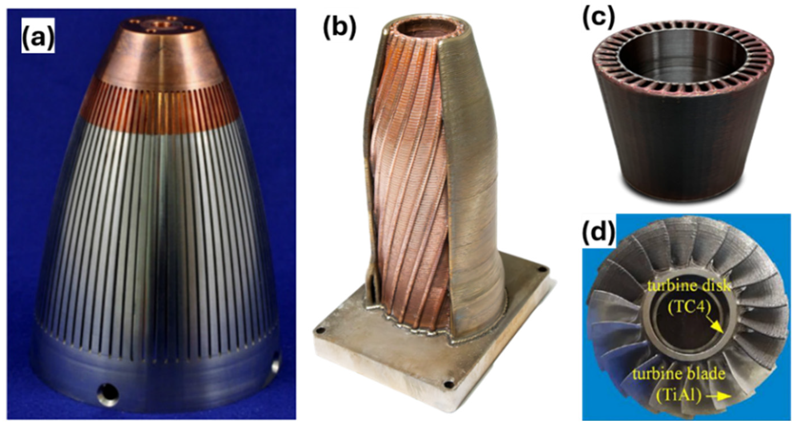
Bimetallic structures are the combination of two distinct metallic materials within a single structure, combining the unique properties of each. The synergistic blending of different metals yields a range of distinctive properties and functionalities that surpass those exhibited by individual components [13]. These structures could satisfy demand for components with improved, tailored, and location-specific properties in high-tech industrial fields. Practical applications of BS include turbine blades [9], channel wall nozzles [10], combustion chamber [18], and dual-material pipes [18]; these are depicted in Figure 2.
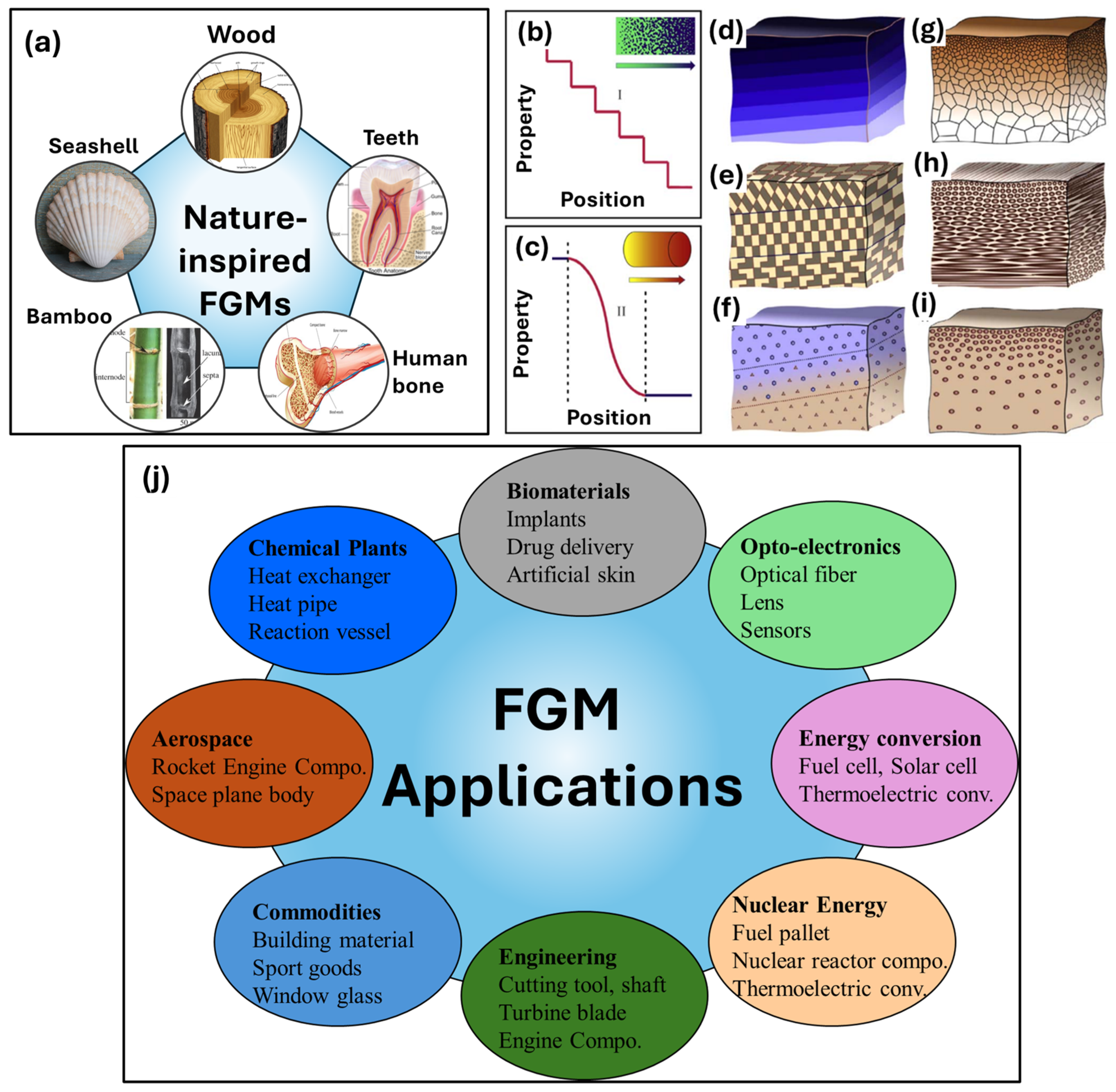
Multifunctional materials with a spatial compositional and microstructural modification specifically designed to govern variations in a range of functional qualities, including mechanical, thermal, and structural, are known as functionally graded materials [19,20,21]. FGMs are new composite materials that have locally customized properties due to their gradual changes in composition and structure across their volume [22,23]. Natural examples of these materials include bones, teeth, wood, bamboo, and seashells as depicted in Figure 3a [22,24,25,26]. The most prominent example is bone structure, where the outer cortical bone is hard and dense, while the inner cancellous bone is porous and spongy, allowing flexibility and strength depending on the load [24]. Like bones, teeth have a hard enamel layer on the outside and a softer dentin layer underneath, providing different mechanical properties based on location [27]. Different layers of wood, like the springwood and summerwood, have varying densities and properties depending on the growth season, creating a natural gradient [25]. In a seashell, the outer layer of seashell is often harder and more resistant to wear, while the inner layer can be pearly and smooth, showcasing a gradient in composition and texture [25]. FGMs can be categorized in several ways according to their size and structure. Based on size, they are classified into bulk and thin FGMs (surface coatings) [28]. Depending on the type of structure, they are also divided into continuous and discontinuous (stepwise) FGMs. Discontinuous FGMs (Figure 3b) involve discontinuous, stepwise changes in the material constituents, whereas continuous FGMs (Figure 3c) lack visible zones or separation cut lines inside the material [14]. Continuous and discontinuous FGMs are further divided into categories: composition gradient, microstructural gradient, porosity/fraction gradient [23,29,30]. Figure 3d–i shows the general forms of gradient materials with different structure types. Figure 3j depicts the advanced applications of FGMs in various fields [14,15,16,31].
Metallic multi-material structures can be manufactured by conventional as well as additive manufacturing (AM) methods. In recent times, AM has emerged as a financially feasible method for multi-material fabrication. WAAM stands out as a promising method for fabricating metallic multi-material structures due to its unique advantages [23,33]. WAAM has been successfully implemented to fabricate metal-based bimetallic structures/functionally graded materials [23,34,35]. Table 2 summarizes the key benefits and limitations of WAAM in this context.

1.2. Bibliometric Analysis

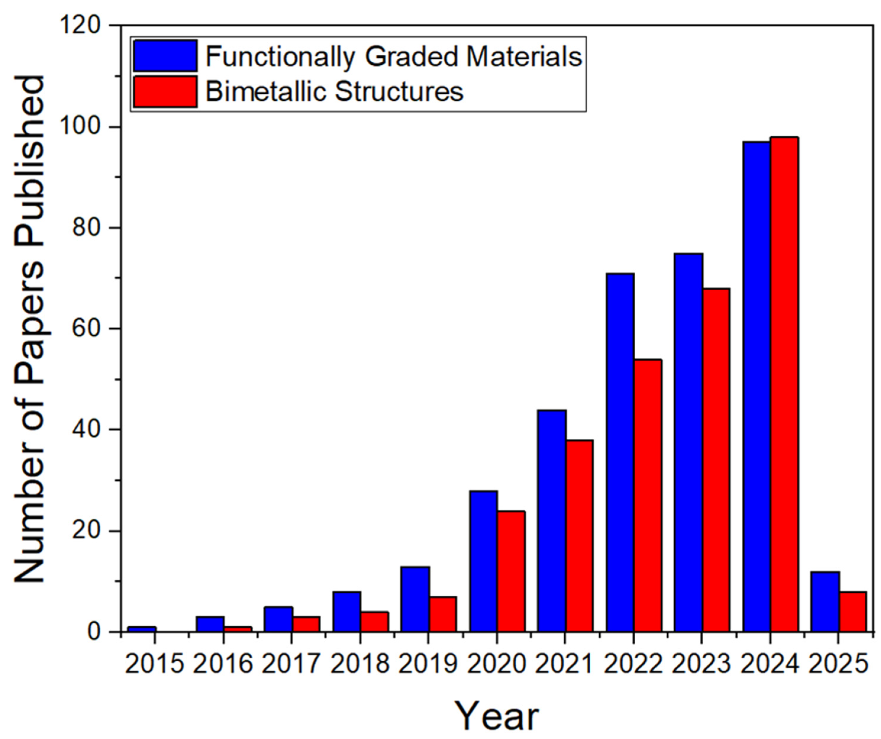
To gauge the growth and prominence of WAAM of multi-material structures, a comprehensive bibliometric analysis was conducted. Figure 4 depicts the trajectory of publications between 2015 and 2025, focusing on WAAM of bimetallic structures and functionally graded materials from the Scopus and Web of Science database. In recent years, there has been a perceptible upsurge in research activity around this research domain, as indicated by the increasing number of publications in this domain. This surge not only highlights the growing interest of scholars in this emerging topic but also underscores the potential benefits the WAAM technique might bring to multi-material structure fabrication.
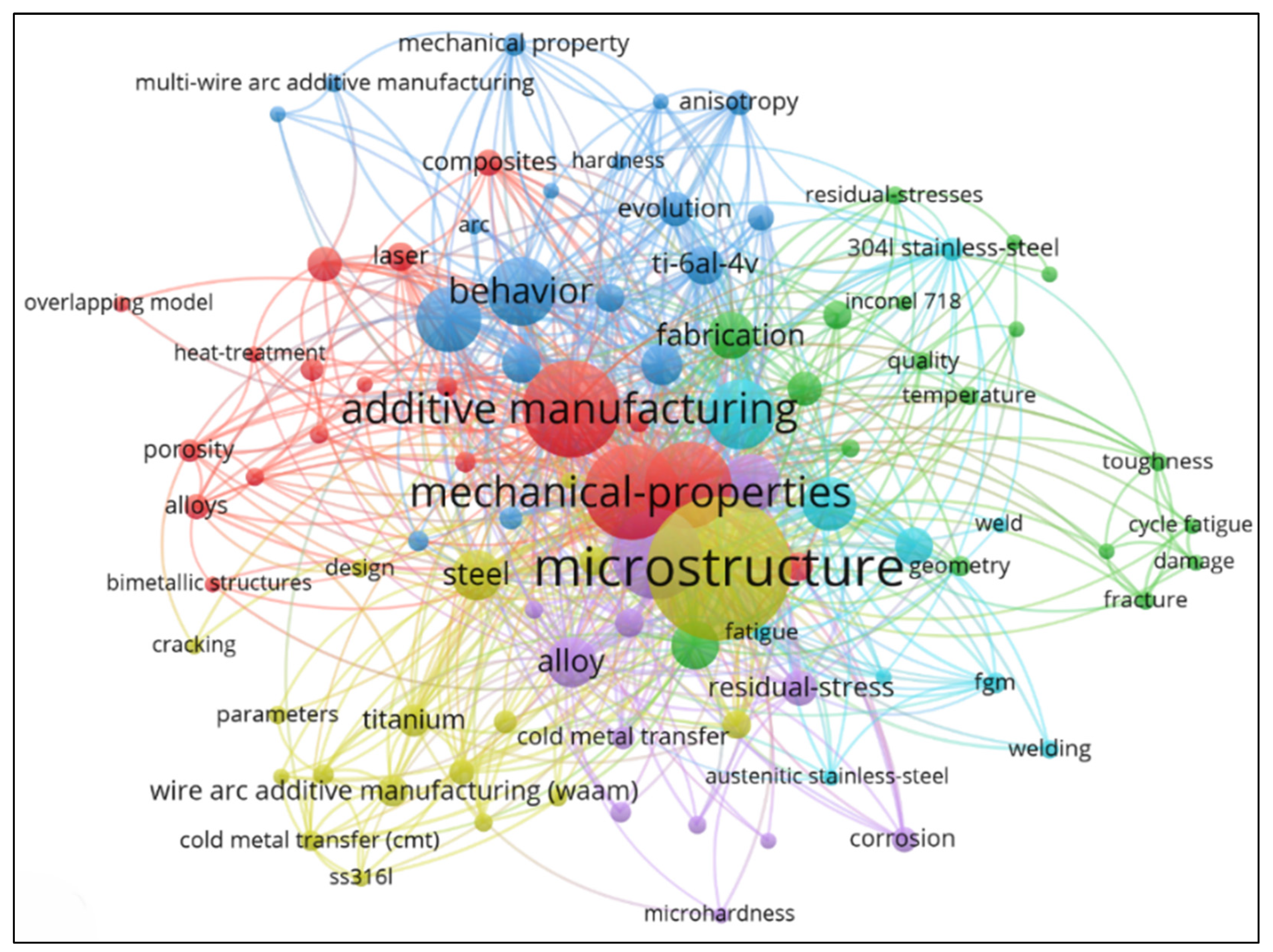
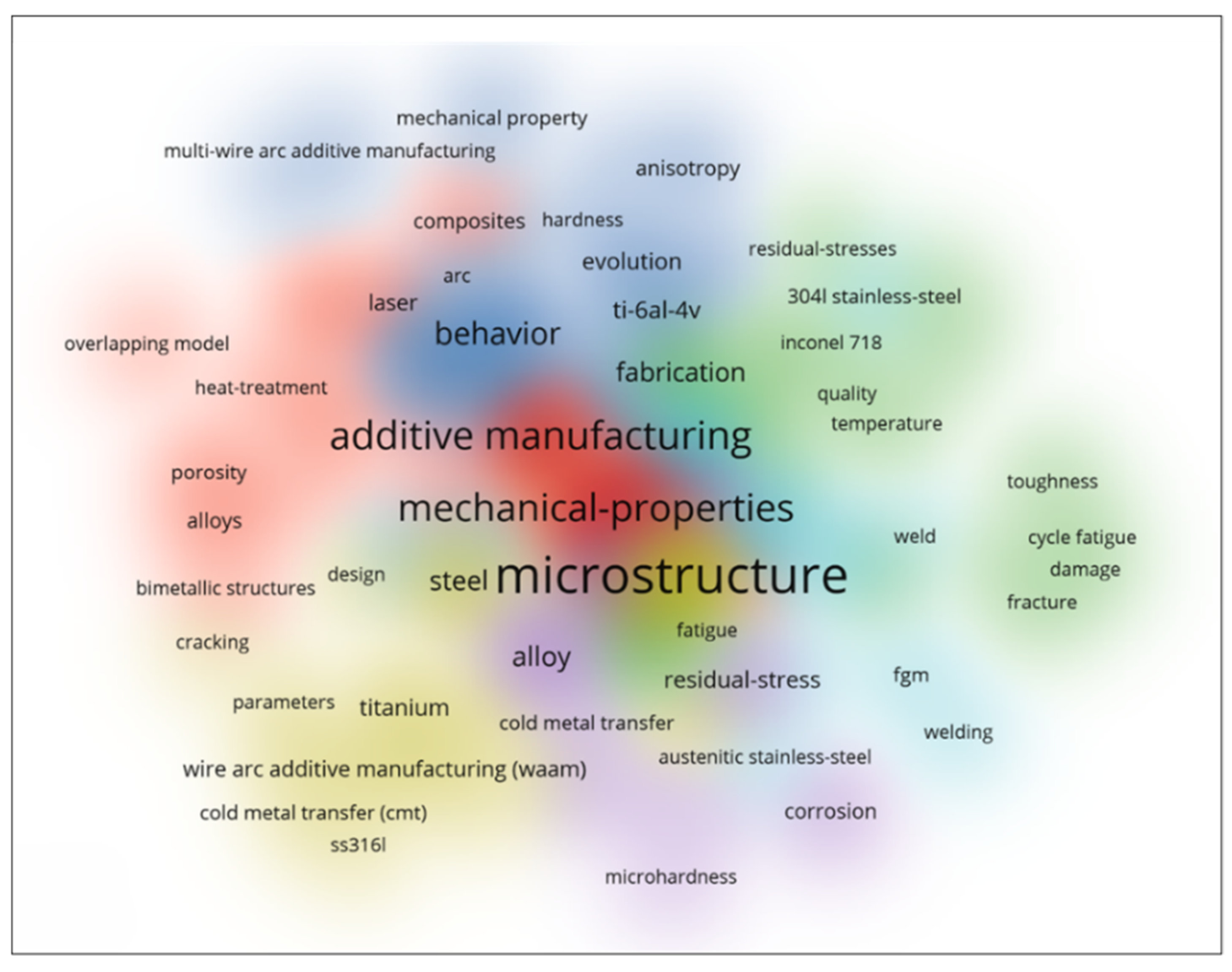
Following the Preferred Reporting Items for Systematic Reviews and Meta-Analyses (PRISMA) guidelines, this review employed a systematic search strategy [36]. Relevant studies on WAAM of multi-material structures from the last decade, specifically published in English, were identified using Scopus, Google Scholar, ScienceDirect, and Web of Science databases. Articles were screened based on titles and abstracts for their focus on WAAM, bimetallic structures, and functionally graded materials. Extracted data included WAAM, microstructure and mechanical properties, process parameters, materials, and applications. The present article employs VOS viewer software (version 1.6.20) to analyze keywords extracted from references [37,38]. Figure 5 presents the resulting network visualization, highlighting connections between these keywords.
A thorough analysis of term co-occurrence clustering was carried out utilizing data from the Web of Science and Scopus to comprehend the research environment in the field of WAAM of multi-material structures. Figure 6 shows that the term “Microstructure” is a heavyweight in the dataset. Given the opportunities and challenges presented by the WAAM, its consistent appearance over time (average publication year of 2024) suggests that understanding the microstructural characteristics of materials remains paramount.
Many researchers have documented reviews on metallic multi-material structure fabrication using various AM techniques [2,13,14,15,16,17,23,33,35,39,40,41]. This article aims to provide a comprehensive and systematic review of all the aspects of the research on metallic multi-material fabrication using WAAM. This review provides a comprehensive understanding of the present state and scientific challenges in WAAM of multi-material structures. We focus on key developments in deposition strategies, characterization methods, material compatibility, process optimization, interface engineering, challenges, and emerging research directions to address existing limitations. An overview of bimetallic structures and functionally graded materials along with bibliometric analysis, is provided in this section. Conventional and Additive manufacturing methods for multi-material structure fabrication are described in Section 2. Different scientific studies on WAAM of multi-material structures are reviewed in Section 3. Challenges associated with the WAAM of multi-material structures are elaborated on in Section 4. Section 5 outlines key future directions for advancing WAAM-based multi-material manufacturing. Finally, the conclusions of this review are summarized.

2. Multi-Material Structure Fabrication

2.1. Conventional and Additive Manufacturing Methods

Bimetallic structures could be processed using conventional manufacturing methods, such as casting [42], forging [43], and welding. Under the welding, electron beam or laser welding [44,45], explosive welding [46], ultrasonic welding [47] and friction stir welding [48,49] are employed for bimetallic structure fabrication. Additional methods include brazing [50,51], diffusion bonding [52,53], and the transient-liquid-phase (TLP) [54,55] technique. Among the conventional methods, welding techniques are well-established methods for joining two different metallic materials. While welding methods are cost-effective for joining, they present significant challenges, such as the creation of a substantial heat-affected zone (HAZ), cracking at the joint, and the formation of brittle intermetallic phases, particularly when joining dissimilar metals [56]. Also, welding techniques introduce weld defects, such as porosity, residual stress and a change in microstructure and properties at the weld joint. Moreover, traditional approaches for processing of BS involve multi-stage production, intricate system configuration, extended lead times, and high production costs [13].
Thin FGMs are produced by conventional manufacturing techniques such as gas-based and other methods [28]. Chemical vapor deposition (CVD), physical vapor deposition (PVD), thermal spray, surface reaction spray, are gas-based techniques, whereas other methods include Self-propagating high-temperature synthesis, plasma spraying, Electrode deposition, and ion beam assisted deposition [57,58]. Manufacturing Bulk FGMs utilizes liquid-phase and solid-phase approaches [23,59]. Liquid-phase techniques employ centrifugal casting, gel-casting, sedimentation, tape-casting, slip-casting, electrophoretic deposition and directional solidification. However, the solid-phase approach includes powder metallurgy, spark plasma sintering processes [57,58,59,60]. Conventional manufacturing methods for FGM fabrication are energy intensive, lack precise control, require many tools/assemblies, involve material wastage and have defects such as porosity in produced FGMs parts [20,23,59,60].
As mentioned above, conventional multi-material structure fabrication methods pose significant challenges including the formation of brittle IMCs, cracking, poor interfacial bonding, reduced strength, and defects. Consequently, during the past few decades, additive manufacturing (AM) techniques have become more significant in the creation of multi-material structures. Unlike traditional methods, AM constructs structures layer by layer. It is a fabrication method that creates 3D parts via the accumulation of materials. AM is defined as a process of joining materials to make objects from 3D model data, usually layer upon layer, as opposed to subtractive manufacturing methodologies [61]. Key benefits of AM technology include reducing the cost of the final part by reducing material wastage, short lead times, and the ability to produce complex geometry parts without any special tooling [62]. According to ASTM/ISO 52900:2017 [61], it can be categorized into seven broad categories: (1) binder jetting, (2) powder bed fusion, (3) directed energy deposition, (4) sheet lamination, (5) material extrusion, (6) material jetting, and (7) vat polymerization. Among these seven processes, only the first four categories are related to metals. The four categories of AM technology namely powder bed fusion (PBF), direct energy deposition (DED), binder jetting (BJ), and sheet lamination (SL) are used to build metal parts through what is nowadays called metal additive manufacturing [17]. The classification of metal additive manufacturing (MAM) processes is illustrated in Figure 7. The PBF system consists of a powder bed, powder delivery system, and energy/heat source (laser/electron beam). The PBF process begins with the creation of a 3D CAD model, which is numerically ‘sliced’ into several discrete layers. For each layer, a heat source scan path is calculated which defines both the boundary contour and some form of fill sequence, often a raster pattern since the heat source is typically an energy beam [63]. Each layer is then sequentially bonded on top of each other. PBF processes spread powdered material over the previously joined layer, ready for processing of the next layer. A hopper supplies the powdered material which is then spread uniformly over the powder bed build platform area via a roller or blade [64]. Powder bed fusion can be further classified as Direct Metal Laser Sintering (DMLS), Selective Laser Melting (SLM), Direct Metal Laser Melting (DMLM), and electron beam melting (EBM). The significant drawbacks of the powder-based processes for multi-material structure fabrication are the high powder material requirement, wastage, low deposition efficiency, difficulty in controlling heating and cooling rates, and limitations on part size [15,16,20].
The direct energy deposition process involves feeding powder or wire through a nozzle onto a built part and melting it using a laser beam/electron beam or electric arc as a heat source. DED processes are further classified based on feedstock (powder or wire). Powder-based DED uses a laser/electron beam to melt the powder; however, wire-based DED uses a laser/electron beam/electric arc to melt wire [63,65]. Further, depending upon the heat source, the DED processes are categorized as Laser Engineered Net Shaping (LENS), electron beam freeform fabrication (EBF3), Wire + Arc Additive Manufacturing (WAAM), and wire laser additive manufacturing (WLAM).
Binder jetting consists of spraying a stationary loose bed of powder placed on a built platform with a liquid adhesive through an inkjet-style printer to stick the powders together into a cross-section, layer upon layer [64,65]. Binder jetting technology requires no support structures and prints much more accurate objects compared to metal powder bed fusion. Sheet lamination joins thin metal sheets layer upon layer using ultrasonic welding or friction stir welding, to build an object that is subsequently cut according to the desired metal part geometry [65].

2.2. Wire DED Additive Manufacturing Processes

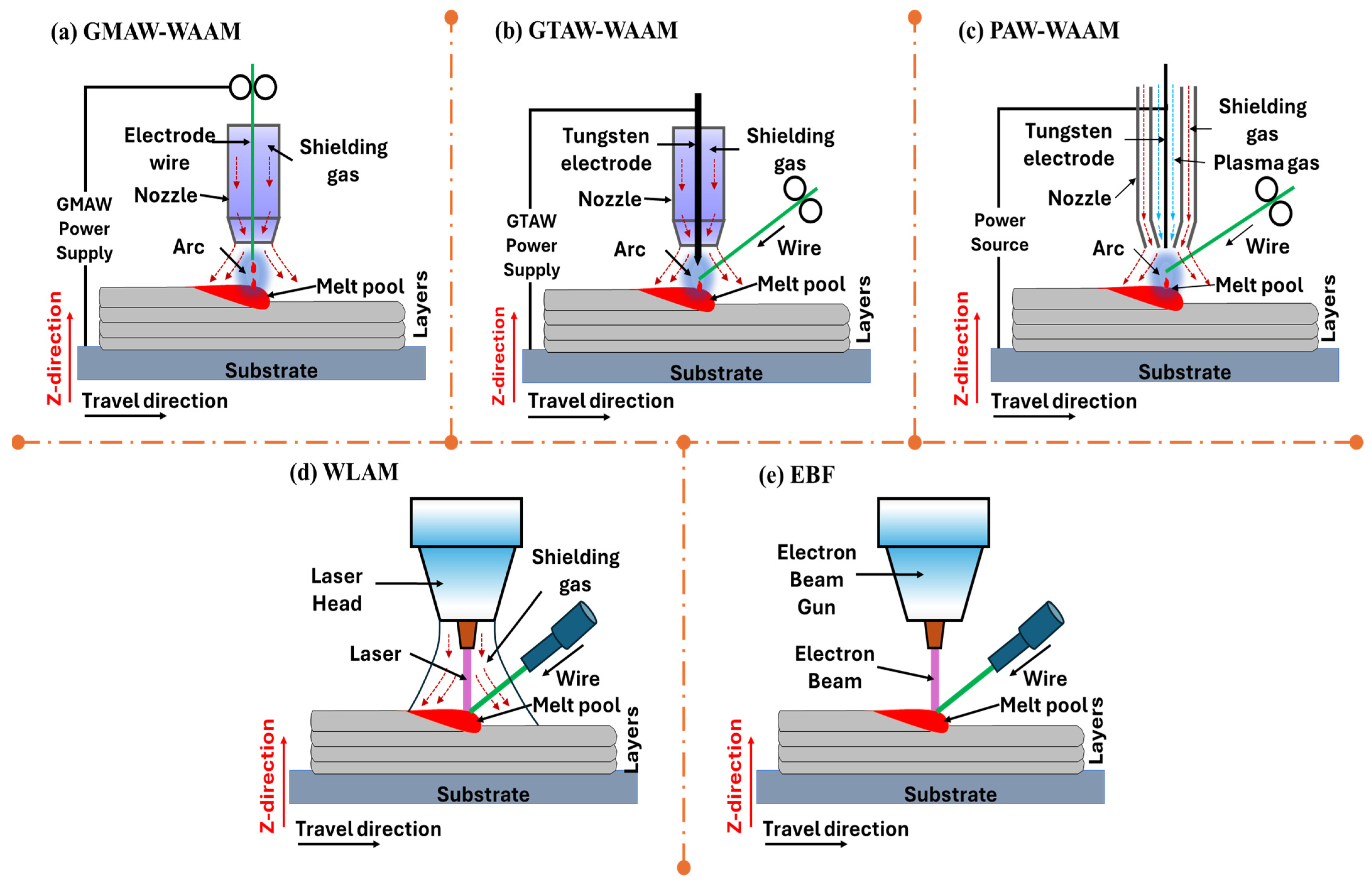
Wire directed energy deposition (Wire-DED) is an advanced additive manufacturing (AM) technique that builds metal components layer by layer by melting wire feedstock using a high-energy heat source [66]. As a subset of directed energy deposition, this process is particularly effective for producing large, structurally robust parts with high material efficiency. The Wire DED process involves material feeding, energy source activation, layer deposition, solidification, and cooling. The process is governed by advanced control systems that ensure precision in wire feeding, energy input, and deposition path. Wire DED processes utilize various heat sources, such as electric arc, laser, plasma and electron beams. Based on these heat sources, wire DED processes are further classified as wire-arc additive manufacturing (WAAM), wire laser additive manufacturing (WLAM) and electron beam freeform fabrication (EBF3) [66,67]. Wire laser additive manufacturing (WLAM), also known as laser wire-feed metal additive manufacturing, uses a laser beam to melt a metallic alloy wire [68] as illustrated in Figure 8d. In EBF (Figure 8e), a metallic wire is fed directly into an electron beam to create metal preforms out of a molten metal pool [69]. WAAM uses an electric arc as a heat source to melt a metal wire. WAAM has three types: Gas Metal Arc Welding (GMAW), gas tungsten arc welding (GTAW) and plasma arc welding (PAW) [67,70]. In GMAW, the wire serves as a consumable electrode, as illustrated in Figure 8a. The arc formed between the wire and the workpiece melts the wire material, depositing it on the substrate’s surface. GMAW is commonly used due to its high deposition rates, high material utilization, shorter lead time, and compatibility with a wide range of materials [71]. In GTAW-based WAAM, an electric arc is generated between a non-consumable tungsten electrode and the substrate material for heat generation, as shown in Figure 8b below. A filler wire is fed from the side, which melts due to the heat of the arc and deposits on the substrate’s surface to create the desired geometry. GTAW provides higher precision but slower deposition rates. The PAW process, like GTAW, uses a non-consumable electrode. However, PAW differs from GTAW in that the plasma arc is restricted in a nozzle, making it more efficient [71]. In PAW, an arc is formed between the tungsten electrode and the water-cooled nozzle, as illustrated in Figure 8c. plasma arc welding (PAW) offers a controlled heat zone for improved precision and repeatability [67,70,72]. But the initial cost of PAW is very high compared to GMAW and GTAW. Laser-based heat source generates localized heat with high precision, enabling fine feature control and excellent surface quality [68]. Plasma and electron beams are suitable for highly controlled environments, such as vacuum chambers, to produce parts with minimal contamination [69,72]. Advantages of WAAM are high deposition rates, material efficiency, wide material compatibility, scalability, and repair capabilities [73]. The freedom of design, filler wire availability, and low capital cost of the WAAM process allow the fabrication of multi-material structures [15,16,20]. However, WAAM has challenges, namely: surface finish, residual stress and distortion, process control, and dimensional accuracy [74].

3. Recent Research Progress in the Wire-Arc Additive Manufacturing of Multi-Material Structures

3.1. Bimetallic Structures: Deposition Strategies

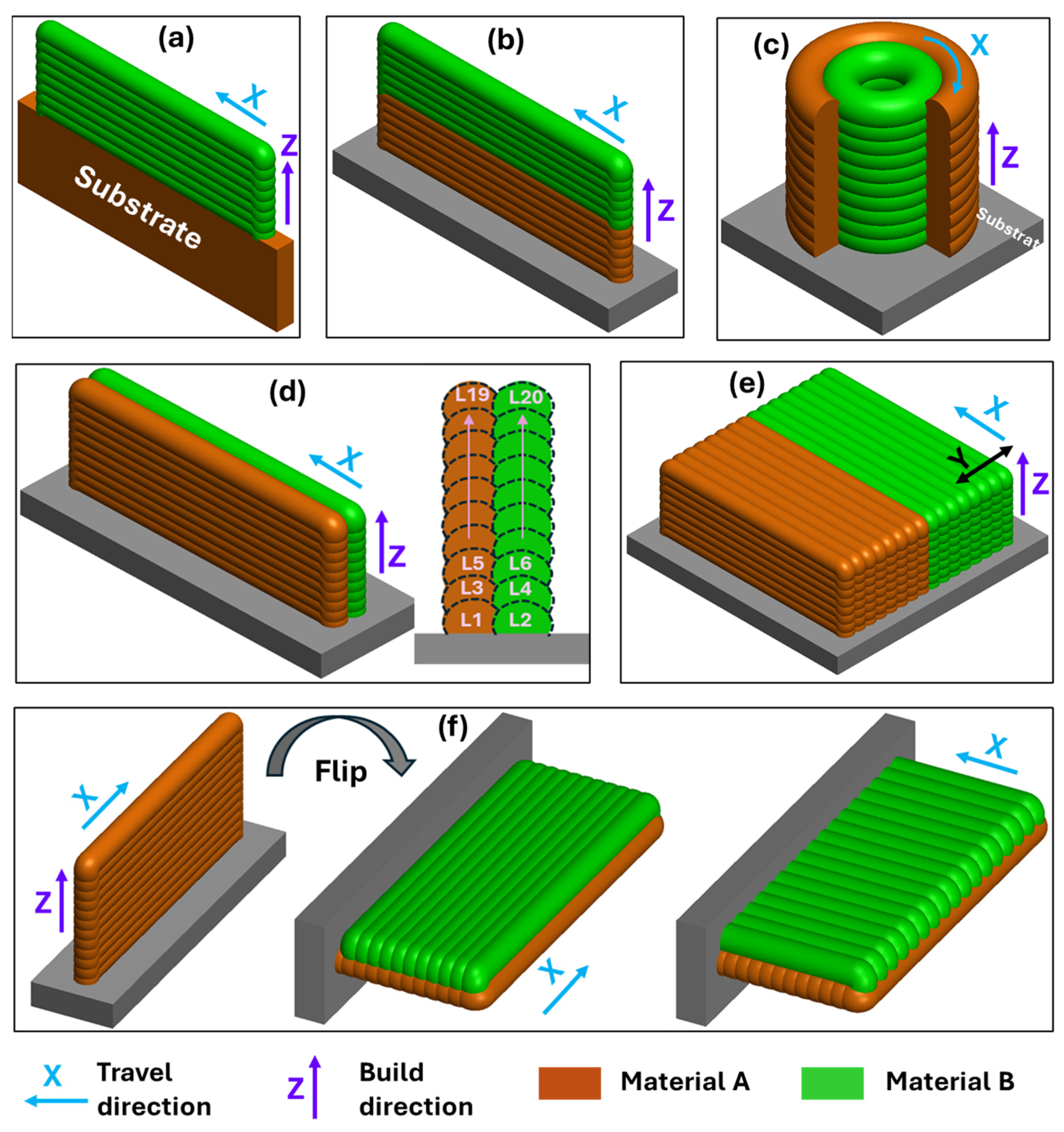
Bimetallic structures can be realized by employing sequential deposition of parent materials. Parent materials may be deposited one over other or side by side. Figure 9 illustrates the various deposition strategies employed by researchers to fabricate bimetallic structures. As shown in Figure 9a, material B is deposited onto the substrate of material A. This approach has been utilized by researchers [75,76,77,78,79,80,81]. In Figure 9b, material B is layered onto a prior deposit of material A, a strategy widely adopted in BS fabrication [82,83,84,85,86]. Figure 9c presents a radial bimetallic structure produced using a multi-torch DED-arc system utilized by Bandyopadhyay et al. [87] Figure 9d,e showcases interweaving deposition, where overlapping beads are deposited in multiple layers along the y-axis and the y-z plane, respectively, a technique employed by researchers [88,89,90,91]. In Figure 9f, material A is first deposited as vertical thin wall, which is then positioned horizontally to facilitate the deposition of material B on its lateral surface. This deposition strategy was applied by Marefat et al. [92] in the fabrication of LCS-SS316L bimetallic structures.

3.2. Bimetallic Structures: Fabrication and Characterization Studies

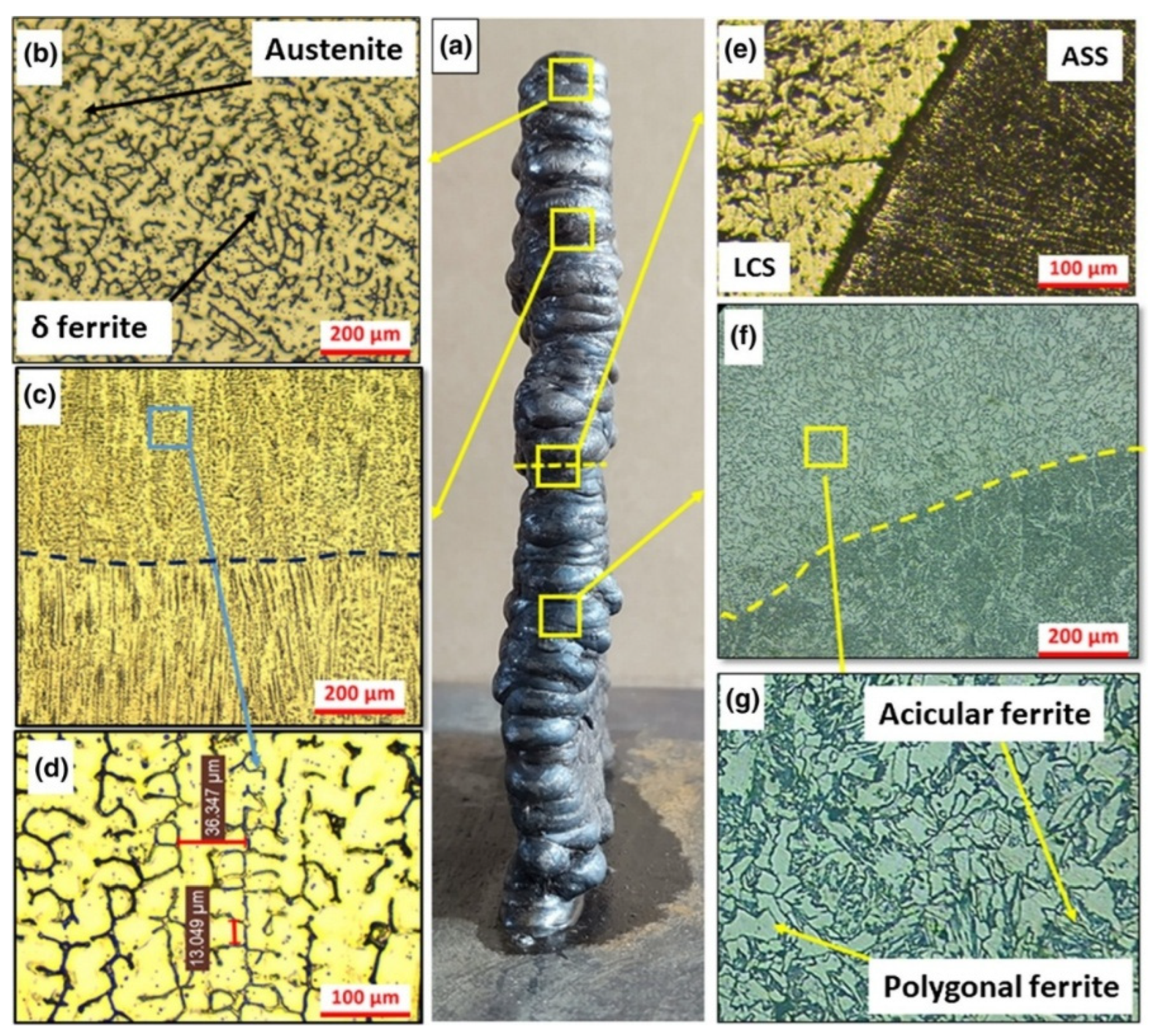
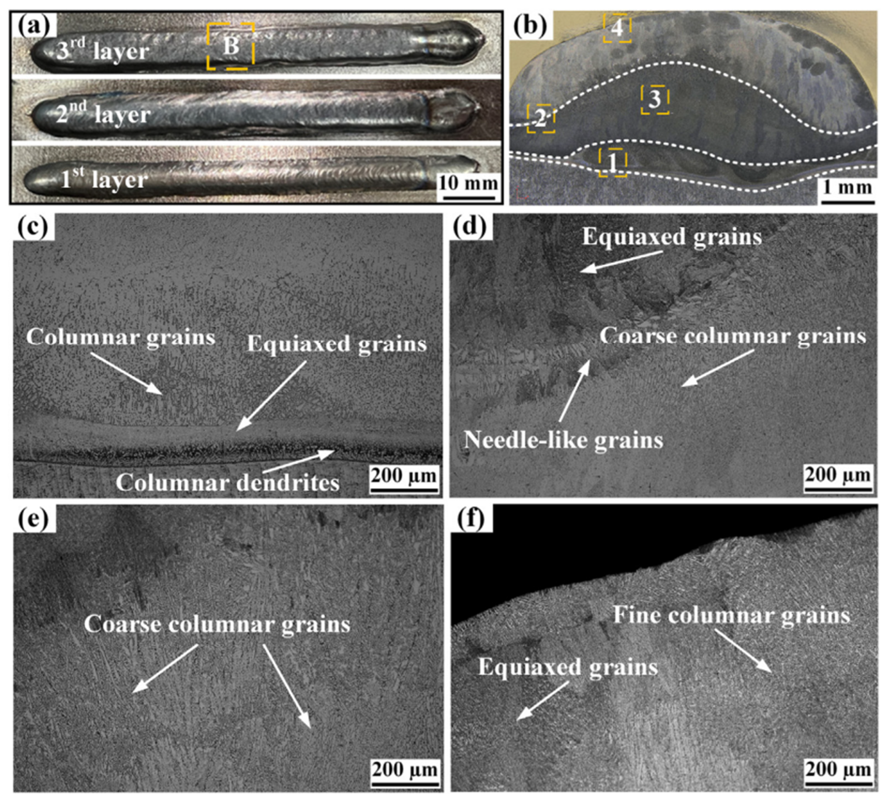
Recent research [91,93,94,95,96] have demonstrated the effectiveness of WAAM in fabricating high-performance steel on steel bimetallic structures with robust interfacial bonding and properties customized for specific applications. These studies employed twin-wire WAAM utilizing arcing as a heat source in their projects for bimetallic structure fabrication, such as ER70S-6/SS316LSi and SS304L/SS304L. This demonstrated the acoustic phase transition between states, enhanced hardness values, and further elevated ductile characteristics. This indicates that WAAM can manufacture durable multi-material steel bimetallic components for industrial applications. Thirugnanasambandam et al. [97] produced a balanced WAAM thermal cycle in SS316L/SS308L structures that resulted in defect-free bonding, with consistent characteristics. Singh et al. [98] investigated the microstructure and mechanical properties of NiTi/SS BS fabricated via WAAM. The study revealed a smooth and defect-free interface, but brittle intermetallic phases (TiCr2, TiNi3, and FeNi) formed at the joint, leading to high hardness (400 HV) but reduced toughness. The ultimate compressive strength was 570 MPa, with failure occurring at the NiTi side due to intermetallic-induced brittleness. Aslam et al. [99] developed a SiC/AISI304 stainless steel clad layer on low-carbon steel (LCS) using the GMAW process and observed significant improvements in hardness and wear resistance. The clad layer exhibited a uniform distribution of SiC reinforcement and the formation of hard intermetallic compounds, including CrSi2, Mn3Ni2Si, Fe2C, Fe5C2, and Cr7C3, which contributed to enhanced material properties. The microhardness of the clad layer increased to 504 HV, compared to 180 HV for the LCS substrate. In a effort to optimize interface performance, Marefat et al. [92] explored deposition strategies in low-carbon steel/316L stainless steel systems using WAAM, revealing that deposition orientation, especially perpendicular builds, plays a more critical role in enhancing interfacial shear strength than surface preparation. In support of these findings, Gurol et al. [100] demonstrated that robotic WAAM facilitates defect-free interfaces between ER70S-6 and ER316L, with no discernible transition region from ferrite to austenite, even in areas where Fe and Cr resulted in localized hardness increases, further highlighting the significance of interface management in multi-material arc additive deposition. Raut et al. [86] successfully fabricated a bimetallic wall via cold metal transfer (CMT)-WAAM with austenitic stainless steel (ASS) (SS316LSi) over low carbon steel (ER70S-G) BS. The structure exhibited a clean, defect-free interface with strong metallurgical bonding, as illustrated in Figure 10a–g. The microstructural study revealed vermicular δ-ferrite within an austenitic matrix in the ASS area as shown in Figure 10b, transitioning to columnar grains and equiaxed structures across layers as demonstrated in Figure 10c,d. Mechanical tests revealed that the bimetallic sample cracked on the LCS side, with a UTS of 493 MPa with 22% elongation, suggesting that the interface exhibited greater strength than the LCS. A significant increase in microhardness at the interface resulted from chromium diffusion, signifying effective metallurgical contact across the bimetallic boundary.
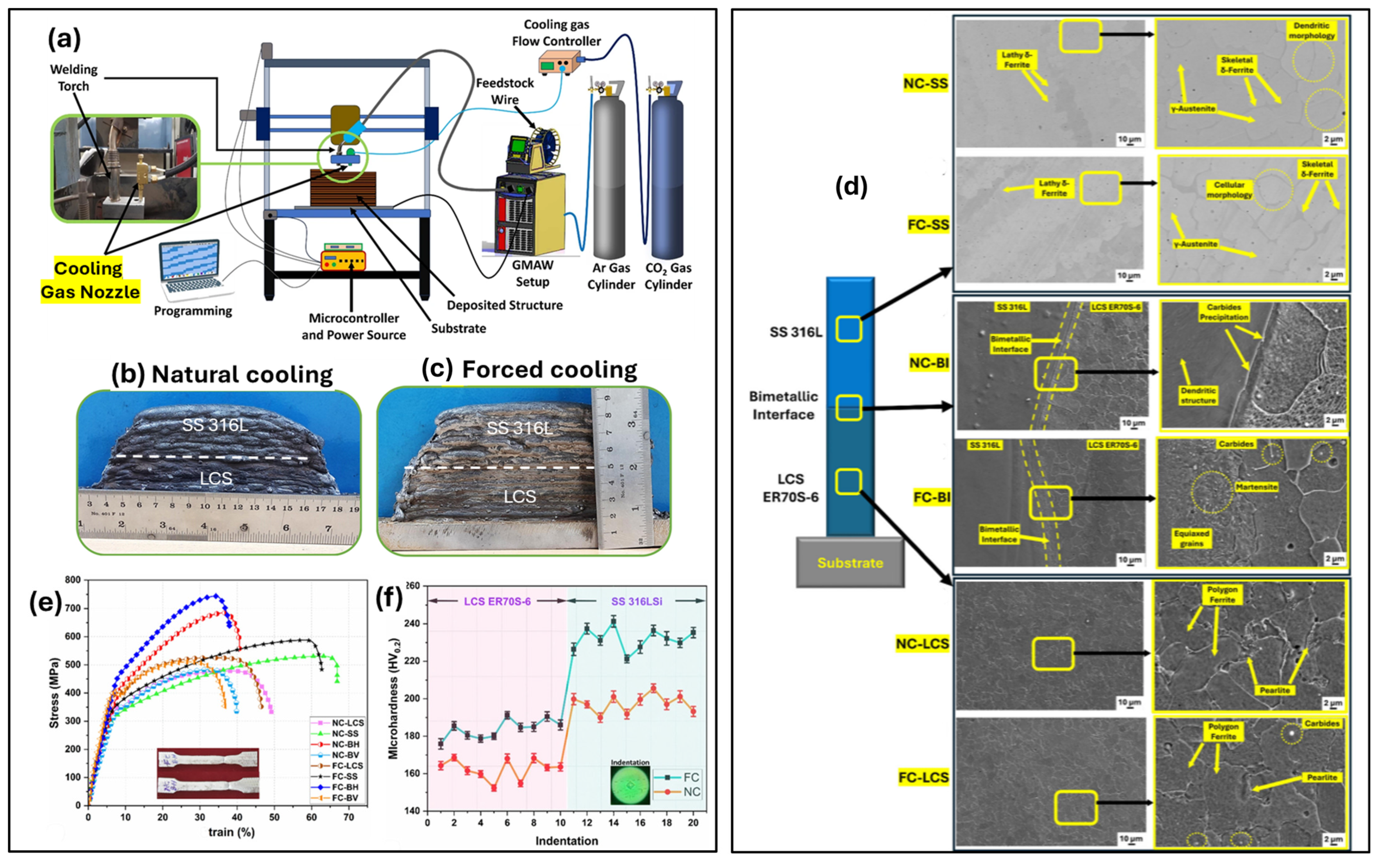
Badoniya et al. [101] investigated the influence of interlayer forced cooling (FC) using CO2 gas during WAAM deposition of LCS (ER70S-6) and SS316L bimetallic structures. Figure 11a–f demonstrates the WAAM equipment with forced cooling setup, the deposited thin walls, microstructure, and mechanical property results. Forced cooling enhanced the microstructure, augmented the ferrite and martensite composition at the interface (Figure 11d), and improved microhardness and tensile strength. This is also evidenced by the stress–strain curves of materials (Figure 11e) and the microhardness profile (Figure 11f). These improvements are attributed to grain refinement, martensite formation, and carbide precipitation at the interface.
Zhai et al. [94] evaluated the manufacturing and mechanical properties of WAAM-produced ER70S-6/S355 bimetallic joints. Microstructural examination of the data revealed that ER70S-6 exhibited equiaxed grains and a robust interface bond devoid of flaws. Digital Image Correlation (DIC) was employed to acquire deformation behavior data during tensile loading, as illustrated in Figure 12. Localized deformations commenced at a total strain of 0.41 percent in ER70S-6, progressively spreading and escalating inside the gauge section. Post-yielding, deformation predominantly transpires on the ER70S-6 side before disseminating over the entire specimen and finally the as built BS sample failed on S355 side. The DIC strain maps confirmed that strain localization progressively increased during the entire stage, and effective load transfer occurred multiple times at the interfaces of these different joints, illustrating the robust mechanical integrity of the connection.
Tyagi et al. [102] and Ahsan et al. [103] conducted detailed investigations on SS316L–IN625 BS fabricated using laser wire directed energy deposition (LW-DED) and CMT-based WAAM, respectively. In both instances, there is an absence of cracking or delamination at the metallurgical interface. Approximately 55 μm with refined epitaxial grain development and consistent elemental diffusion, the narrow defect-free transition zone was attained. The bimetal sample exhibited an ultimate tensile strength of 550 MPa and an elongation at break of 41.6%. The ductility and interfacial strength are exceptionally high. On the other hand, the WAAM approach is used to attain consistent crystallographic orientation at the interface for FCC structure materials. Despite the presence of a minor quantity of Laves phase on the IN625 side, the specimen maintained a continuous hardness of 220–240 HV, while achieving a UTS of 600 MPa with 40% elongation at fracture. It is noteworthy that both samples are fractured on the SS316L side near the interface. Simultaneously, Wu et al. [104] investigated crack formation in steel–nickel bimetallic components manufactured using WAAM by reproducing crack propagation and integrating multiple simulations. Their investigations demonstrated that nickel is the primary locus for crack formation resulting from thermal cycling, residual stress, and the accumulation of components such as Nb and Mo, which induce Laves phase segregation or carbide production at grain boundaries. The study identified that grain orientation, dislocation density, and high-angle grain boundaries are critical factors influencing crack sensitivity, significantly impacting interface design for multi-material additive manufacturing. Zhang et al. [82] indicated that the microstructure and performance of 316L/IN625 BS were affected by their deposition sequence in CMT-based WAAM. When 316L is initially deposited in the series, its interface stays impeccable, leading to a ductile fracture. Conversely, when Inconel 625 is initially deposited, the interface is susceptible to crack formation due to the accumulation of Laves phase and elemental intermixing, resulting in a mixed brittle-ductile fracture. This suggests that a different deposition strategy may modify the overall performance of the bimetallic structure.
Kumar et al. [105] discovered that a graded IN635/SS304L interface enhanced the strength and hardness of multi-material structure as compared to abrupt interfaces. Wu et al. [88] established an interweaving deposition pathway in steel/nickel, integrating the characteristics of both materials to create a metallurgically bonded interlock interface with solid-solution strengthening, achieving a tensile strength of 634 MPa. Sridar et al. [106] discovered that WAAM-fabricated P91/Inconel 740H bimetallic structures exhibited an extensive gradient zone with intergranular fractures resulting from thermal mismatch and Nb-rich carbides. Cracks can be mitigated by altering the deposition sequence and using graded transition layers. Munusamy et al. [84] conducted a study on the impact of build orientation on WAAM-fabricated Grade 91 steel and Monel 400 BS. Microstructural and mechanical analyses at 0°, 45°, and 90° (relative to the build direction) reveal considerable anisotropy. The properties in the built direction exhibited the best balance of tensile strength and ductility. Microstructural analysis showed a defect-free interface with no intermetallic, favorable for structural integrity in thermal and corrosion-resistant applications. Hwang et al. [107] applied variable-pressure rolling during WAAM of Inconel 625–SS308L BS, which can significantly improve the build quality. Rolling transforms the coarse columnar grains into an equiaxed structure devoid of sweep or deviation, eliminating the anisotropy present and enhancing its hardness and strength, particularly in the softer SS308L. This approach proved effective in enhancing interface bonding and mechanical reliability without introducing defects.
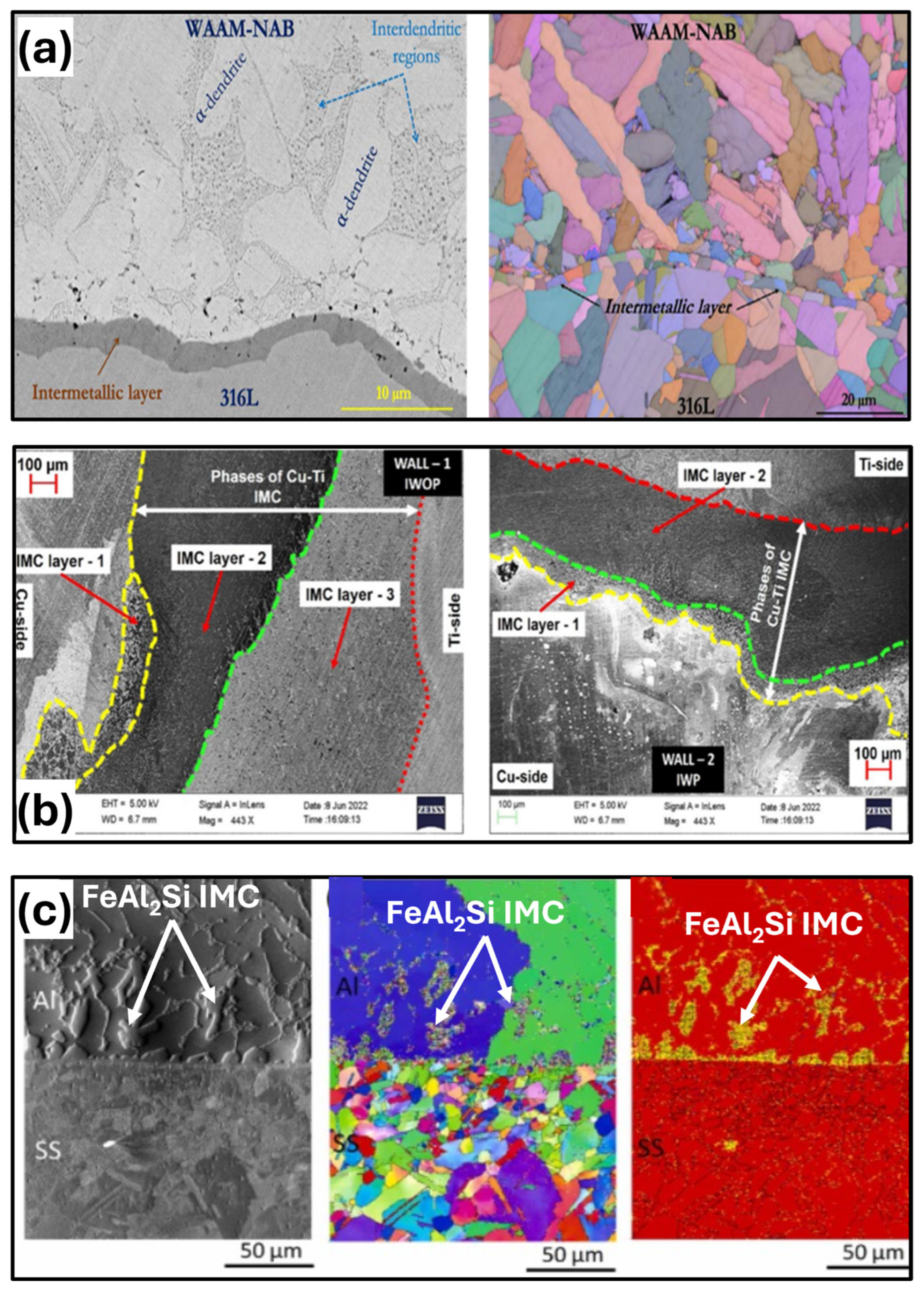
The advancements in WAAM have significantly enhanced interfacial bonding and mechanical properties of BS through the application of innovative material combinations, interlayer strategies, and thermal control techniques. Several studies were employed to address compositional transition approaches to improve interface integrity. Zhang et al. [108] incorporated an intermediate Cu–Ni layer into a silicon bronze/steel bimetallic system, successfully removing microcracks and enhancing diffusion, resulting in a tensile strength increase of 66%. Liu et al. [109] used a metal inert gas (MIG) bypass technique for the deposition of aluminum bronze/steel BS. This deposition inhibited Fe–Al intermetallic compounds and increased the ultimate tensile strength by 39%, while achieving a ductility around 84% higher. Mishra et al. [110] investigated interface engineering in a Ti6Al4V/IN718 system. The utilization of a CuSi interlayer, both with and without copper powder. This study revealed that the CuSi layer greatly reduced the intermetallic (IM) thickness and enhanced bonding. However, the introduction of copper powder resulted in the formation of brittle Ti5Si3, which diminished tensile strength and plasticity. The optimal mechanical performance (UTS ~152 MPa) was attained in the construction devoid of copper powder. Simultaneously, Xiang et al. [111] investigated the microstructure and mechanical properties of high-performance nickel–aluminum bronze (NAB)/SS316L composite BSs for marine and structural applications. The formation of a thick Fe3Al-rich metallurgical layer at the interface enhanced yield strength by 51% and hardness by 30% compared to cast NAB. The microstructure exhibited fine grains, minimal evidence of coarse intermetallic development, and the existence of stacking defects, leading to delayed failure during a tensile test. Singh et al. [112] utilized WAAM to fabricate a NiTi–Cu bimetallic structure. They determined that the interface was intricate, featuring solid intermetallic phases such as Ti(Ni, Cu)2 and Ti2(Ni, Cu)31, whereas the adjacent corner proved to be rather more challenging. However, the intermetallic also represented a minor constituent that contributed to the enhanced brittleness of the joints and significantly diminished the overall compressive strength. The as-built components exhibited minimal martensitic transformation; however, heat treatment at 500 °C for 12 h significantly enhanced the phase’s suitability for applications such as bending and compression, demonstrating the substantial impact of post-processing on performance in WAAM applications involving NiTi–Cu joints.
CMT-WAAM was employed to fabricate graded SS316L-Cu structures without cracks. There was not only smooth diffusion across layers, but also the formation of spherical and dendritic structures of Fe, with intermetallic phases missing. Research performed by Tomar and Shiva et al. [113] has confirmed that CMT-WAAM is a technique that efficiently generates defect-free steel-copper components with controlled hardness and microstructures. Simultaneously, Chen et al. [114] advanced the field by employing twin wire-arc additive manufacturing (T-WAAM) to fabricate NiTiCu shape memory alloys (SMAs). They achieved excellent composition control and in situ alloying of NiTi with 20.8 at% Cu, resulting in a microstructure predominantly composed of B2 and B19 phases, along with many Ti-Cu intermetallics as illustrated in Figure 13. This novel alloy exhibited a transformation hysteresis of 7.1 °C, markedly lower than the 24.4 °C of nickel–titanium wire, along with an elevated transition temperature. These characteristics render twin-WAAM an excellent source for function-specifiable SMAs required in high-precision domains. Munusamy et al. [115] examined the impact of Laser Shock Peening (LSP) on WAAM fabricated BS composed of Grade 91 steel and Monel-400. LSP process resulted in residual stress reduction, grain refinement, and enhancement of tensile strength of Grade 91 steel. It increased from 1140 MPa to 1280 MPa. Results of EBSD and grain boundary mapping demonstrated that LSP resulted in a substantial reduction in grain size and an increase in the number of low-angle barriers. Post-LSP images highlight enhanced grain refinement with a more uniform arrangement of grain boundaries, demonstrating LSP’s effectiveness in modifying microstructural features. These attributes enhance interfacial adhesion and fatigue resistance, rendering the structure appropriate for the most extreme petrochemical or maritime conditions.
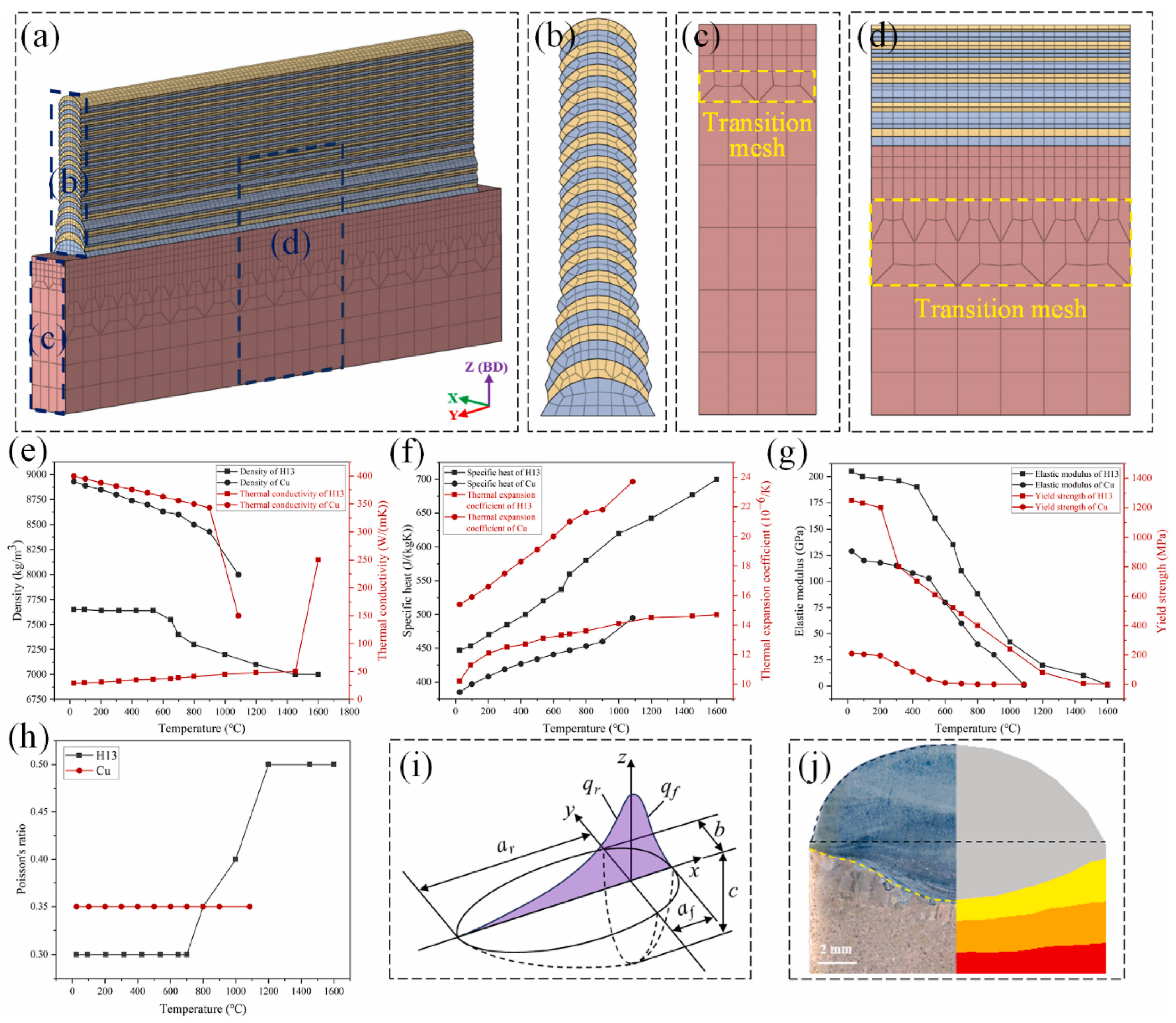
The investigation by Du et al. [81] employed WAAM to fabricate intricate H13 steel and Copper BS and sought to comprehend the interface formation and thermal performance by numerical simulation. The simulation effectively modeled heat distribution, material behavior, and dynamics within a molten pool during layer-by-layer deposition as illustrated in Figure 14a–j. The model helped to predict how copper’s high thermal conductivity influenced the solidification and intermixing modes at an interface. The simulation revealed the formation of an extensive molten pool and a mushy zone beneath the H13–Cu contact, which is crucial for mitigating defects such as micro-cracks or pores. The model’s reliability was validated with actual samples, affirming its application in enhancing process parameters to optimize dissimilar metal deposition and improve the quality of the interface.
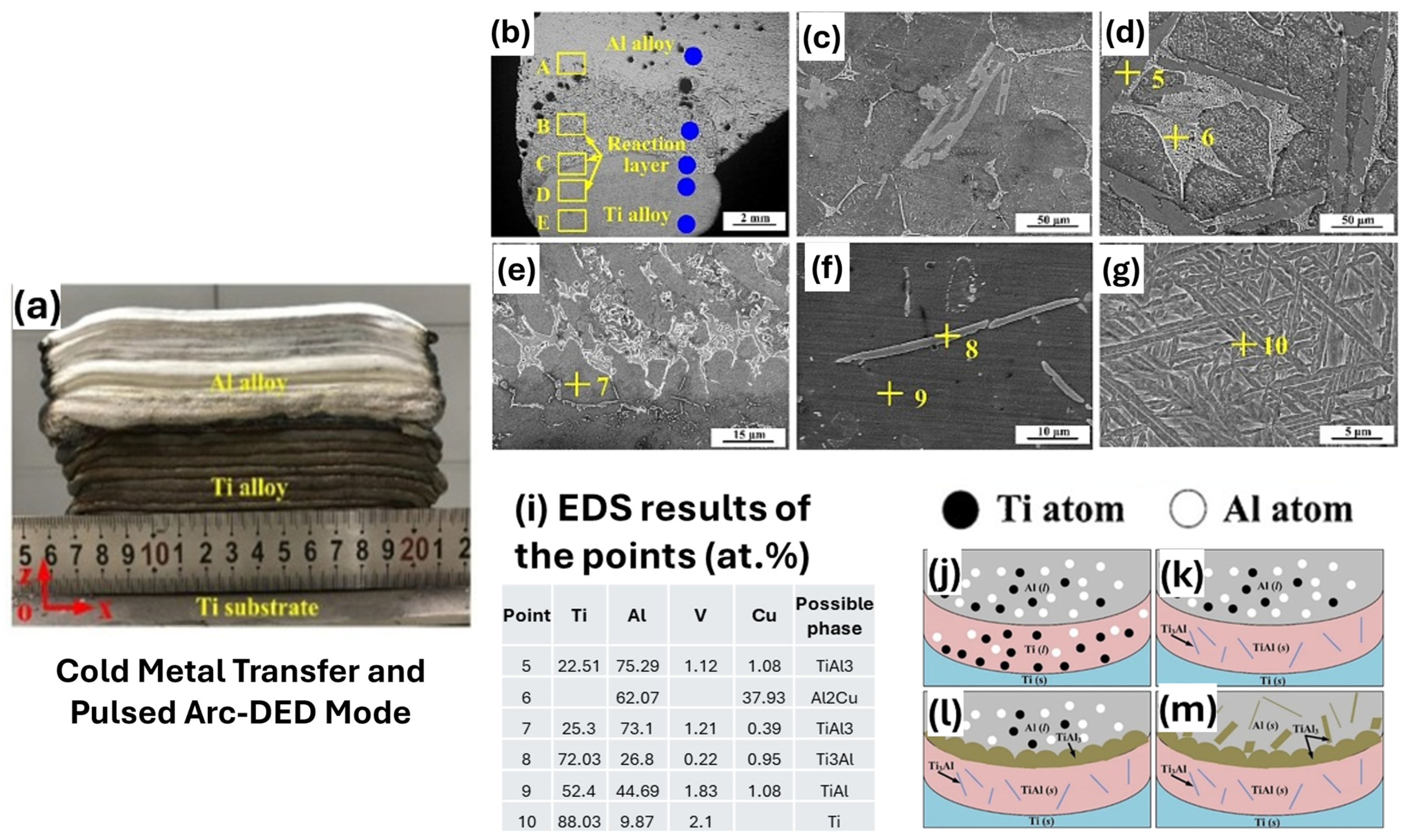
Tian et al. [116] investigated the microstructural evolution of a Ti-Al bimetallic structure processed by WAAM. Their research demonstrated that the quantity of Al layers significantly influenced intermetallic compound (IMC) production at the Ti/Al interface. Xia et al. [117] demonstrated that post-hot compression of WAAMed Ti/Al BS can produce Ti/Al bimetallic composites with strong interfacial bonding and reduced porosity. As the titanium fraction increases, the tensile strength rises, making these structures promising for lightweight applications. Naiqiang et al. [83] utilize CMT based WAAM with a Nb interlayer deposited via TIG welding to study a crack-free Ti6Al4V/Al6.21Cu bimetallic structure for the automotive and aerospace industries. The Nb interlayer functioned as a diffusion barrier, hindering the formation of Ti-Al intermetallic brittle compounds and improving the mechanical strength by 27.9%. Additionally, some researchers conducted additional research aimed at regulating interfacial heat input to prevent the formation of brittle intermetallic compounds. In the work of Tian et al. [85], Ti-6Al-4V/Al-6.25Cu BS were fabricated using WAAM with CMT and CMT+P. DC-CMT, known for its low and stable heat input, resulted in a narrow reaction layer, limiting intermetallic growth. In contrast, CMT+P, with its higher peak current and extended arc-on time, introduced a significantly higher heat input, promoting deeper melting at the Ti interface and leading to a thicker, more complex reaction zone. SEM microstructure illustrated in Figure 15c–g and EDS mapping, verified the existence of intermetallic compounds such as TiAl3, Al2Cu, TiAl, and Ti3Al. The reaction layer mechanism, depicted in Figure 15j–m, demonstrates how enhanced thermal input facilitates profound Ti melting, TiAl nucleation, and the extensive growth of TiAl3. CMT+P improves droplet transfer and deposition efficiency for aluminum, but it also hastens intermetallic formation, elevates residual stress, and diminishes overall joint toughness, illustrating a distinct trade-off between process efficiency and interfacial integrity.
Many efforts were made to fabricate steel/aluminum bimetallic structures. Ozlati et al. [118] provided practical engineering solutions for the integration of steel and aluminum using WAAM, transcending the laboratory research focus on aluminum-based bimetallic additive manufacturing. They utilized a roll-bonded transitional joint to execute a consolidation operation. This method effectively inhibited the formation of brittle Al-Fe intermetallics at the interface under the designated conditions. Abdul Karim et al. [77] processed SS316L—Aluminum ER4043 BS employing CMT-WAAAM process and studied the effect of heat input on the bead geometry, porosity, and microstructures at the interface, with a specific emphasis on the intermetallic compound (IMC) formation, and the subsequent impact on the joint strength of the structure. An intermetallic compound (IMC) layer, primarily composed of FeAl2Si, forms at the interface. IMC layer thickness increased with heat input. UTS of low heat input condition BS was approximately 105–130 MPa, which is among the highest reported for bimetallic steel-Al joints. Rangasayee et al. [80] manufactured steel—aluminum BS by using CMT-WAAAM and compared the IMC layer thickness at bimetallic interface to that of blown powder DED processed steel—aluminum BS. The CMT process, with its inherently low heat input, led to a significant reduction in intermetallic thickness at the bi-metallic interface compared to the blown powder DED technique. Multi-scale characterization of the bi-metallic interface revealed two different intermetallics, i.e., Al2FeSi in the 4043-aluminum side and BCC (BCC A2 + BCC B2) in the 316L steel side. Ji Liu et al. [119] employed MIG welding with bypass current and forced cooling to produce WAAM of aluminum bronze (AB) and steel BS. They investigated the influence of post-processing heat treatment at 650 °C for 6 h with air cooling, to enhance interfacial integrity and mechanical performance. In the as-fabricated state, the interface is sharp with limited Cu–Fe diffusion. After heat treatment, the diffusion layer widens (~7 µm), showing increased intermixing of Cu, Fe, and Al with no brittle Fe–Al IMCs formations. The material’s ductility improved markedly after post-heat treatment: 58.5% in the horizontal direction and 26.8% vertically, with the enhanced interface toughness.
WAAM also demonstrated the feasibility of fabricating refractory alloy based bimetallic structures. Jadhav et al. [79] investigated the microstructures and mechanical properties of a bimetallic structure (BS) of Ti6Al4V-NbZr1 manufactured by WAAM. Investigations demonstrated that UTS (367.5–543.5 MPa) of BS was superior to that of NBZr1 due to interdiffusion Nb and Ti, absence of pores and intermetallic phases at the bimetallic interface. The interfacial microstructures comprise an island area and a dendritic zone with solid solutions of (β Ti, Nb) and (α + β Ti, Nb), respectively. In another study, Jadhav et al. [75] fabricated TZM-NbZr1 BS using gas tungsten arc welding GTAW-WAAM process and observed non-uniformly distributed pores in the deposited NbZr1 adjacent to the TZM-NbZr1 interface due to the oxidation of diffused Mo content from the TZM alloy. The ultimate tensile strength of 249 ± 126 MPa was achieved with an elongation of less than 6%. A large deviation in UTS was observed due to the presence of non-uniformly distributed pores at the fractured locations. Gazi et al. [120] extended this research further, by evaluating the effect of hot isostatic pressing and heat treatment on porosity. The combined HIP and HT process effectively eliminated both cracks and porosities from the interface, altering the pore recovery mechanism from micro-void formation to dynamic recrystallisation. Additionally, enhanced Mo diffusion from TZM to NbZr1 was observed at higher temperature. Jadhav et al. [76] successfully fabricated BS composed of tungsten alloy 90WNiFe and In625 using WAAM system with integration of GTAW and CMT processes. The interface exhibited an absence of welding defects such as cracks and porosity. The bonding strength was attributed to the diffusion of chromium, nickel, molybdenum, and niobium from In625 into the γ-(Ni, Fe, W) binding phase, and formation of Ni-Cr-W solid solution.
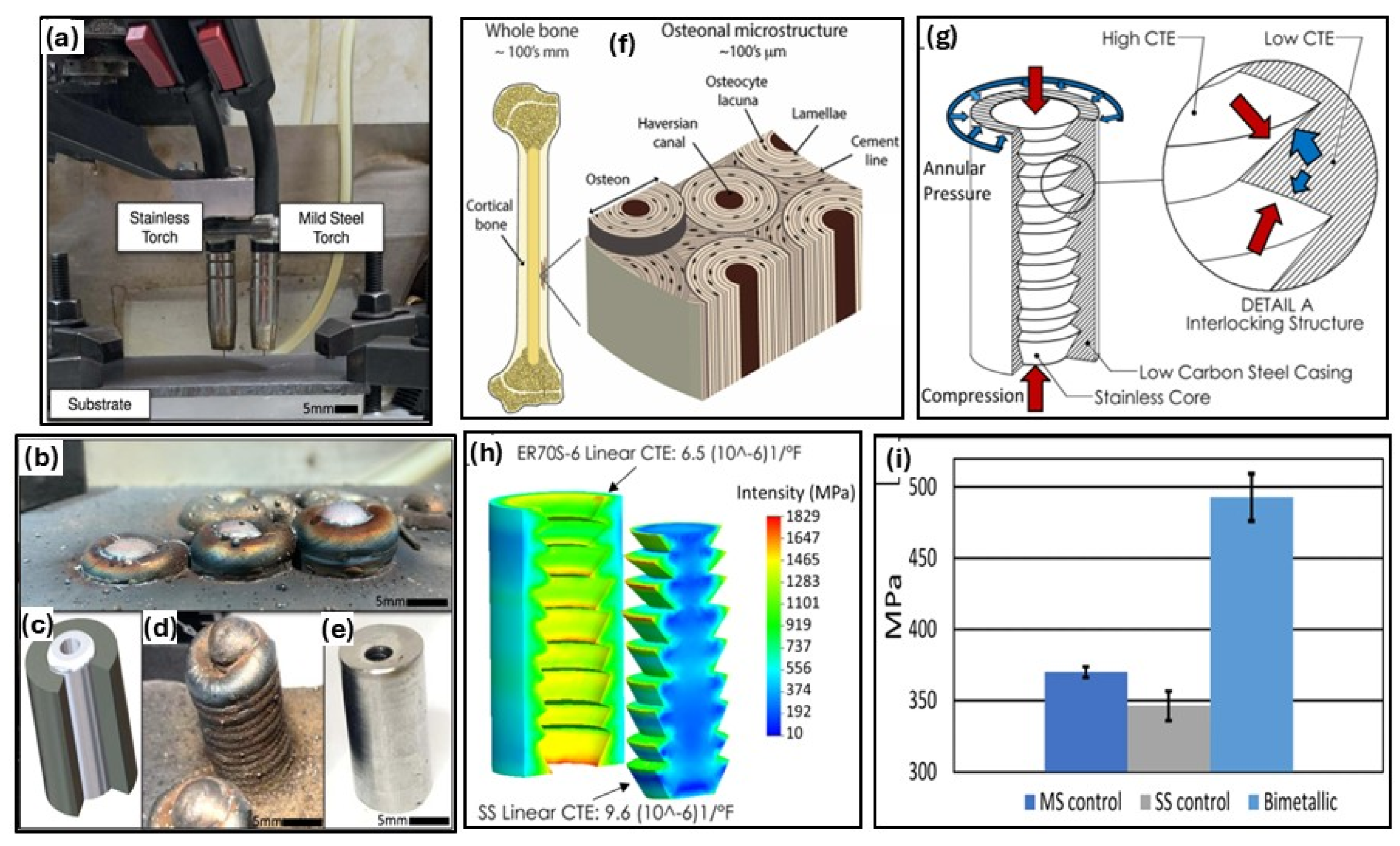
Furthermore, Hauser et al. [121] investigated multi-material WAAM using more common alloys, specifically 5083 and 6060 magnesium-aluminum alloys. They implemented on-site process monitoring, which enabled real-time observation of alloy transitions and ensured process stability in WAAM. This resulted in a defect-free transition zone, where the mechanical properties were predominantly determined by the attributes of the base alloy rather than the interface. Squires et al. [87] introduced a novel radial bimetallic structure that falls under the Dual-torch WAAM setup with a 308L SS core concentrically deposited inside a mild steel casing, illustrated in Figure 16a,b. This configuration aims to replicate nature-inspired concentric and interlocking patterns for biomimetic structures and provide improved mechanical performance via physical and metallurgical bonding. Figure 16g illustrates that the coefficient of thermal expansion mismatch between the SS core and the mild steel shell induces compressive hoop stress during cooling, which will improve the durability. The results (Figure 16i) demonstrate an approximate 38% enhancement in compressive strength of BS compared to parent materials. According to Azar et al. [122] wire-arc DED of a BS made from AA5083 and AA6061 has been found to lead to this highly corrosion-prone interface. Reasons for this include micro-structural differences in the materials, which cause galvanic corrosion; resultant tension stress is an additional factor contributing to cracking.
For a better overview, a summary of studies on bimetallic structures fabricated using WAAM techniques, including GMAW-(CMT), GMAW, GTAW, MIG, and PAW, is presented in Table 3. It summarizes over 50 research articles across several material systems: steel, Inconel, titanium, aluminum alloys, copper/copper alloys, nickel/nickel alloys and refractory alloys. The table provides comprehensive processing parameters, microstructural attributes, and mechanical properties for each system.

3.3. Functionally Graded Materials: Deposition Strategies, Wire Feeding Layout, Arrangement of Torches

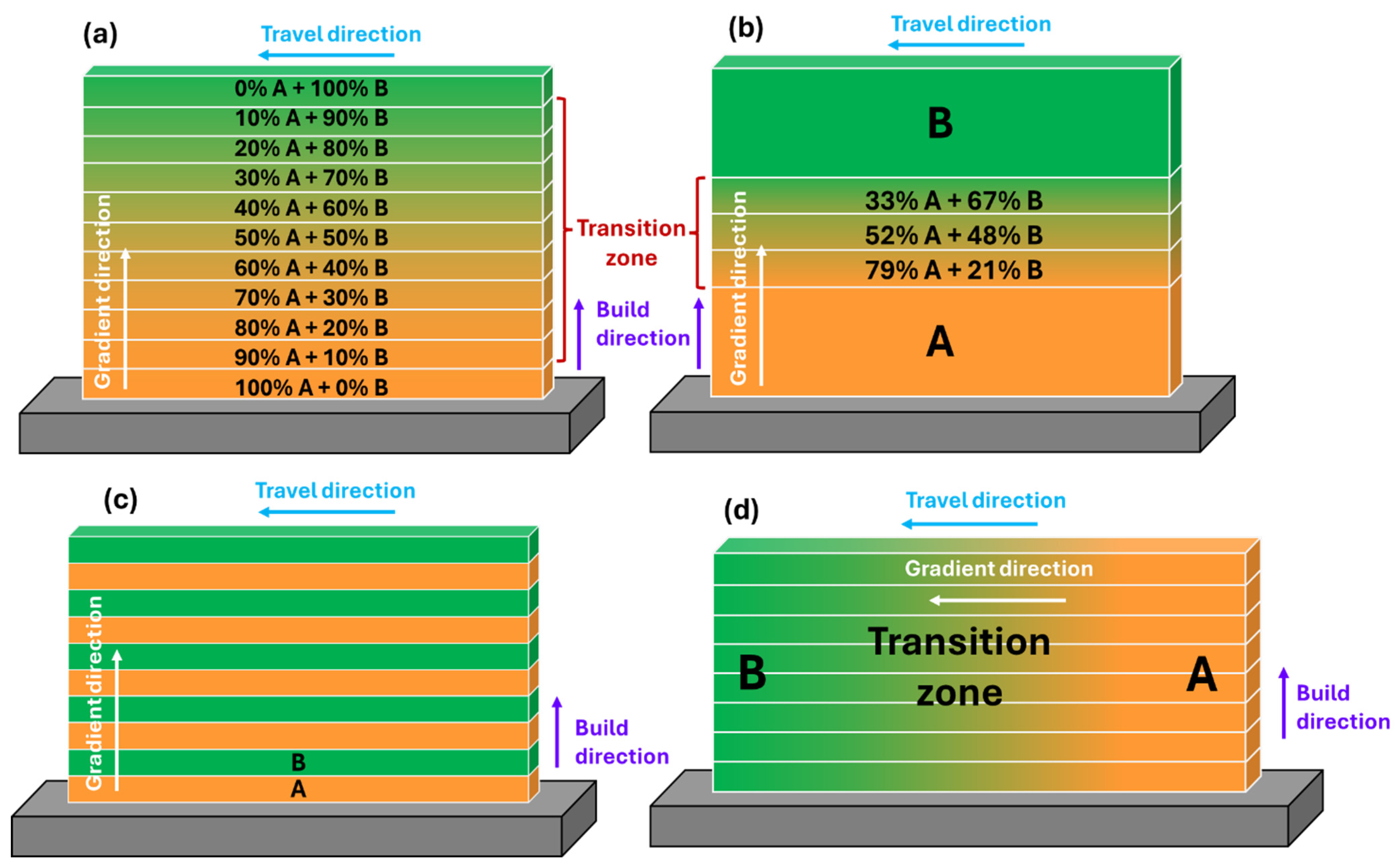
In WAAM, FGMs can be fabricated by changing the composition ratio (wire feed rate) of different wire materials (A, B). Figure 17 represents the various deposition strategies used by researchers to fabricate FGMs. The deposition strategies depicted in Figure 17a–c show a compositional gradient in build direction; however, Figure 17d points to a compositional gradient in torch travel direction. Figure 17a illustrates a deposition strategy with a composition gradient across all deposited layers in the build direction adopted by [139,140,141,142,143]. The deposition strategy in Figure 17b refers to the 3 transition layers with different compositions at the transition zone [144,145,146]. Figure 17c demonstrates that materials A and B were deposited alternately to achieve compositional graduation along the build direction. Researchers [147,148] fabricated FGM of ER70S, 308L Si, 316L Si with this strategy. FGM shown in Figure 17d has a compositional gradient in torch travel direction, employed by [149,150,151,152,153,154]. This type of composition gradient is realized by continuously varying the wire feed rates of two different material filler wires during deposition of each layer.
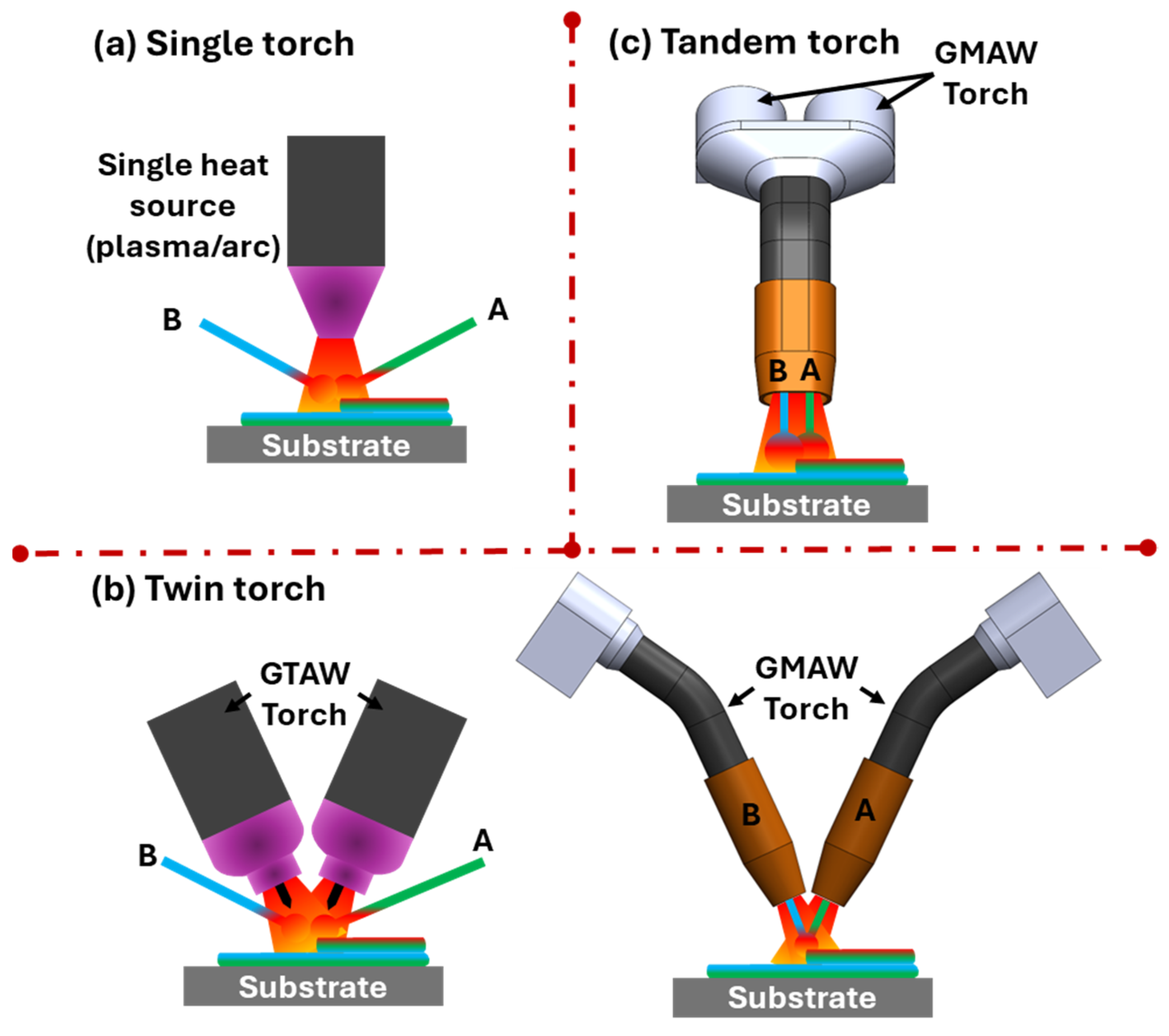
FGM fabrication using the WAAM process can be accomplished through a single heat source or multiple heat sources. Figure 18 showcases the arrangement of heat sources employed for FGM fabrication. Single torch approach indicated in Figure 18a utilizes a single plasma/arc to melt multiple wires (A and B); however, twin torch applies two identical torches (GTAW/GMAW) (Figure 18b). The former approach is most widely used by many researchers [140,141,142,143,144,145,146,149,150,151,152,153,154]. Researchers [128,139,148,155,156] used twin torches to fabricate FGM. Tandem torch arrangement as shown in Figure 18c uses two independent welding systems (power sources, wire feeders, and contact tips) to feed two wires through a single torch, creating a single weld pool [89,157,158].
Different wire feeding strategies, namely left-right layout and up-down layout, employed in FGM manufacturing are illustrated in Figure 19. The left-right layout feeds two wires (A and B) into the molten pool from opposite sides of the torch, whereas the up-down layout feeds two wires (A and B) from one side of the torch. The left-right layout illustrated in Figure 19a is the most used, employed by [139,144,145,146,148,150,154,159,160,161,162,163,164,165,166,167]. Up-down layout depicted in Figure 19b was exercised by [140,142,143,145,149,153,168,169,170] in FGM fabrication. Studies show that the wire feeding strategy affects the shaping, droplet transition mode, droplet transition frequency, microstructure, and mechanical properties of the FGM [151,171].

3.4. Functionally Graded Materials: Fabrication and Characterization Studies

WAAM can produce FGMs with varying chemical composition in the spatial direction to alter the microstructure and characteristics of components. A few examples of fabricated FGMs via WAAM are Ti-TiAl [162], Fe-FeAl [40,172], steel-copper [170,173,174], etc., for specific application-tailored properties. The unique feature of WAAM is its precise control over material deposition and grading, which makes it ideally suited for creating FGMs that meet the requirements of certain high-performance applications under challenging conditions.
The twin wire-arc additive manufacturing process (T-WAAM) employs twin wires with GMAW to produce the FGM [23]. In this setup, both wires were housed within a single torch. However, two separate digitally controlled systems are utilized; each system feeds a different wire through the nozzle into the melt pool. In T-WAAM, the volume fraction of filler wire has a significant influence on the mechanical characteristics of the weld bead, whereas the individual melting rates of the filler wires have an insignificant effect [175]. T-WAAM, also known as dual-wire additive manufacturing, has been effective in producing FGM and intermetallic to achieve material diversity as documented in [176]. Rodrigues et al. [170] fabricated the high-strength low-alloy steel (HSLA) to Cu-Al alloy FGM using T-WAAM. The sample exhibited a flawless microstructure with the formation of nonbrittle intermetallic phases, specifically δ-ferrite, in the interface region. The hardness and electrical conductivity results show smooth variation along the FGM build. Furthermore, the desired tensile strength (690 MPa) with 16.6% ductility of the processed sample suggests its potential for structural applications. The CMT-WAAM was used to fabricate the Cu-SS316L FGM structure [173]. The microstructural analysis evidence the gradual compositional gradient in the graded region without the presence of a metastable or intermetallic phase at the interface. The FGM shows higher mechanical characteristics in the scanning direction compared to the build direction. The higher tensile strength and impact strength, along with ductile fracture, of the fabricated FGM compared to pure Cu enhances its applicability in industrial applications.
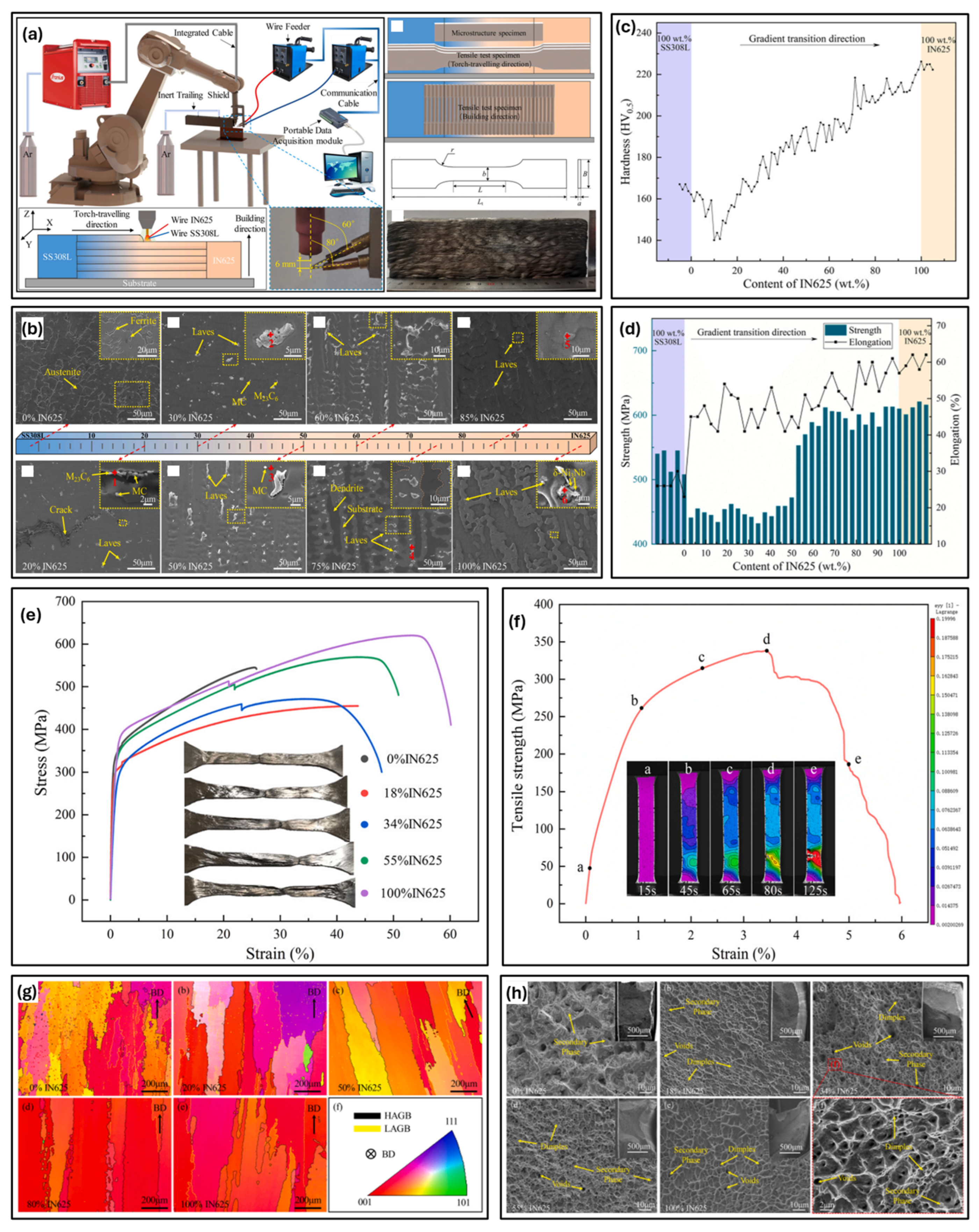
The dual-WAAM (D-WAAM) process provides precise control over material composition, which tailors microstructure with the formation of intermetallic compounds, influencing the mechanical characteristics of the FGM. Li et al. [150] used a novel D-WAAM method to fabricate an FGM as showed in Figure 20, combining SS 308L and Inconel 625 by varying wire feed speed layer by layer. As illustrated in Figure 20c–e the microhardness in the torch-travelling direction and the tensile strength in the building direction decreased first and then increased, but the elongation showed an upward trend. Results show that inferior mechanical characteristics occurred when the Inconel 625 content ranged from 10 to 50 wt.%, due to the presence of secondary phases at grain boundaries. However, the technique offered key benefits, such as customizable gradient paths and structure sizes, especially along the building direction. The lower mechanical characteristics in 10–50 wt.% Inconel 625 for SS 308L and Inconel 625 FGM can be resolved by local Nb alloying. Li et al. [153] investigated local Nb alloying in functionally graded stainless steel 308L/Inconel 625 produced by D-WAAM. It effectively addresses the weakening of solution strengthening in the 10–50% Inconel 625 range by reducing Nb segregation and controlling Laves phase formation. While small Laves phases enhance strength, large chain-like ones negatively affect tensile properties. Nb alloying improved tensile strength compared to unalloyed samples from 385 MPa to 510 MPa and elongation from 8.3 to 16.9%. The defect-free continuous gradient (CG) and sandwich structure (SW) SS316L-IN625 FGM was fabricated via D-WAAM [159]. The EDS mapping shows the gradual variation in the governing elements Fe and Ni for CG-FGM, whereas alternate peaks of governing elements Fe and Ni are observed for SW-FGM. Furthermore, the microstructure analysis revealed a smooth transition from equiaxed to columnar dendrites for CG-FGM, whereas heterogeneous behavior is observed for SW-FGM. The hardness pattern for CG-FGM and SW-FGM are steady and wavy, respectively, which is primarily attributed to the formation of the austenite phase in the structure. The tribological testing showed gradual decrease in specific wear rate with an increase in Ni fraction in CG-FGM. For the SW-FGM, the specific wear rate strongly depends on the adopted design. In another study on Inconel 625-SS316L FGM [177], functionally graded interface revealed a partially mixed zone with a transition from the elongated dendrites to fine equiaxed dendrites. Experimental investigations of tensile test and fracture toughness exhibited ductile mode of fracture. Elemental mapping revealed that there was no evidence of elemental segregation on the fractured surfaces, and the elements were uniformly dispersed.
A SS321/Inconel 625 FGM [178] processed by WAAM demonstrated a very narrow FGM interface without any cracks or fissure. The electron backscatter diffraction results at the interface region revealed continuous crystallographic growth with large, elongated grains in the <001> orientation. FGM sample failed on the SS321 side during tensile testing. To investigate the weakest mechanical characteristics region in IN625-SS308L FGM, Li et al. [149] fabricate FGM via D-WAAM with a transition from 100 wt% IN625 to 100 wt% SS308L along the torch traveling direction. The weakest region with the highest crack sensitivity has appeared near IN625 of 20 wt%. The formation of cracks near the weakest region is primarily attributed to the segregation and aggregation of carbide along the grain boundary. The removal of the weak region compositional range resolves the FGM weakening issue. Furthermore, the tensile strength and elongation increased by 39.5% and 221.7%, respectively, which improves the mechanical characteristics of the FGM. To prepare the FGM, Amiri et al. [179] employed a unique gradient approach to join the plain carbon steel-SS 316L-IN625 using the WAAM process. The tensile properties, including yield strength, ultimate strength, and elongation, reported in tensile testing are 300 ± 6 MPa, 487 ± 10 MPa, and 40% ± 0.15%, respectively. The failure of the tensile specimen in the plain carbon steel region suggests high strength with excellent bonding between the plain carbon steel-SS 316L-IN625. In another research, GMAW-based WAAM has demonstrated the potential to fabricate trimetallic FGM of ER 316L-ER 2205-IN 718 with excellent bonding and enhanced mechanical characteristics along the building direction [180]. Kannan et al. [181] adopted GMAW-WAAM to fabricate the FGM of super austenitic stainless steel SS904L and Hastelloy C-276 with excellent bonding and microstructure of FGM was mainly composed of columnar and equiaxed dendrites with noticeable inhomogeneous features along the built direction. FGM demonstrated YS and UTS of 311.08 MPa and 680.73 MPa, respectively. Cyclic loading test results depicted fatigue resistance of 156 Mpa after sustaining 2 × 10⁶ cycles. Failure was initiated and occurred at SS904L weaker region.
Muthu et al. [182] analyzed microstructure, chemical compositions, grain size, orientation, microhardness, tensile, and impact properties of GTAW-WAAM processed FGM of Alloy 82 and AISI 304L steel. FGM interface revealed no cracks and pores. FGM showed a lower toughness of 33 ± 4 J, due to the maximum stress induced during the deposition of each layer along with the presence of low-angle and high-angle grain boundaries (LAGBs and HAGBs) with intermetallic carbide precipitates. Senthil et al. [183] investigated microstructural behavior and mechanical properties of the ‘Inconel 825—SS316L FGM’ fabricated using CMT based WAAM. The sudden variation in the levels of Ni, Fe and the absence of complete dissemination layers due to the rapid cooling were the reasons for the shift in microhardness at the FGM interface. A continuous cellular dendritic and discontinuous cellular dendritic microstructure observed in the Inconel 825 region, whereas the SS316L region comprised δ ferrite in the primary austenitic γ dendrites. Sainath et al. [184] evaluated the strengthening mechanism and vibrational behavior of 3 FGMs namely SS316L, SS316L + Inconel 625 + Ti6Al4V and SS316L + Inconel 625 + Inconel 718. Results demonstrated that 60% SS316L + 20% INCONEL 625 + 20% Ti6Al4V and 60% SS316L + 20% INCONEL 625 + 20% Inconel 718 has higher strength compared to parent material SS316L. WAAMed FGM has high resonance frequency and higher vibration dampening compared to conventional manufacturing. Senthil et al. [185] addressed the pitting corrosion resistance of Inconel 825-SS316L FGM walls fabricated by WAAM. It was found that the FGM interface and the specimens made of Inconel 825 were more resistant to corrosion than the SS316L specimens. The higher NiO, Cr2O3, and slightly lower MoO3 concentration of the FGM interface, improved resistance to pitting corrosion.
Ti alloys are extensively used in aerospace and biomedical industries. The Ti alloy-based FGM manufactured through the additive manufacturing process is capable of complex structures that are difficult to manufacture by conventional manufacturing processes. Veeman et al. [186] fabricated the CP-Ti-Ti-Grade-9 FGM by using the GTAW-based WAAM technique. Experimental results in this study demonstrate superior hardness, tensile strength, impact energy, and microstructural characteristics compared to wrought alloys. Wang et al. [162] successfully fabricated titanium-aluminide functionally graded material with a designed composition range from pure Ti to Ti-50 at% Al using the double-wire-arc additive manufacturing method (WAAM). The Al concentration along gradient direction of FGM influenced the morphology, microstructure, mechanical properties and oxidation behavior vary greatly. The oxidation resistance degraded at an increasing rate with decreasing Al content due to oxide breakaway occurring in the TiAl alloy matrix that consists of single α2 or α2 +α.
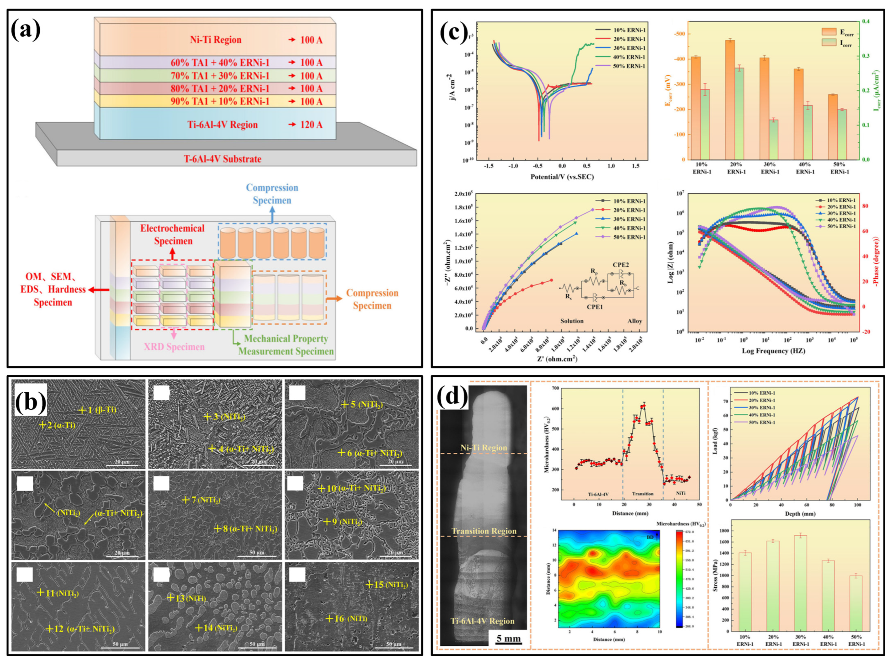
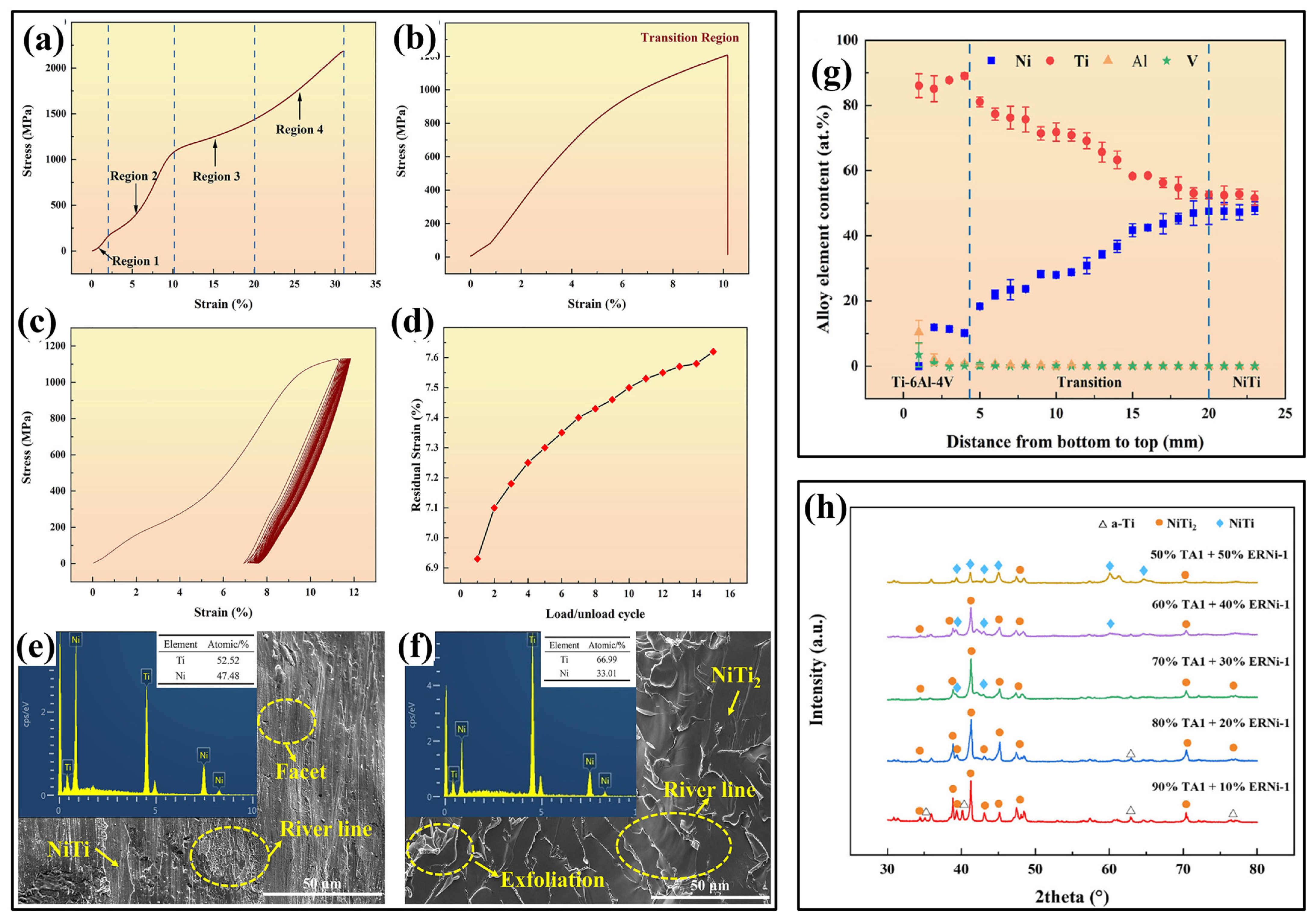
Chen et al. [187] fabricated Ti-stainless steel FGM using TC4 and ER-316L wires via double-WAAM (D-WAAM) process. The results revealed that cracking was initiated when the Fe content reached 50% in the samples. As the Fe fraction increased, the microstructure underwent a phase transformation sequence: from α-Ti + FeTi to Fe2Ti + FeTi + Cr2Ti, and finally to Fe2Ti + Cr2Ti. The highest microhardness observed was approximately 945 HV at 60% Fe. In a high-damage resistance environment, the ferrous aluminide plays a crucial role, as it offers excellent corrosion resistance, oxidation resistance, lower density, and lower costs. However, the lower ductility of Fe-Al intermetallic due to extreme brittleness at room temperature hinders its applications. The FGM of Fe-Al intermetallic with steel can overcome the mentioned shortcomings by transferring characteristics via the intermediate material, with good ductility on the steel side and excellent corrosion resistance on the intermetallic side. Shen et al. [160] fabricated Fe-Al layers with varying Al fractions from 0 to 50 at% on DH36 low-carbon steel using the WAAM process. The microstructure investigation reveals that the continuous composition gradient in the vertical direction, from 100% steel substrate to 50% Al at the top layer, agrees with the designed composition. Mechanical property evolution exhibits an increasing trend in hardness in the vertical direction from bottom to top, resulting from the formation of iron aluminides (Fe3Al and FeAl) upon adding the Al fraction. The middle layer with a 36 at% Al content shows the highest ultimate tensile strength and elongation, basically due to a lower Al fraction and relatively smaller grain size compared to the substrate near region. In contrast, in the top region, the properties are degraded due to a higher ceramic fraction, which makes the layer brittle. In another research, Zhang et al. [172] fabricated FGM transitioning from SS304 to Fe-40Al using the D-WAAM process, employing ER304 and ER1070 filler wires. As the aluminum content increased from the bottom to the top layers, microstructural analysis revealed a sequential phase transformation: γ-Fe → γ-Fe + α-Fe → α-Fe → Fe3Al → FeAl. Cracks were observed in the FeAl region, where the Al content approached 40%, attributed to high residual stresses and limited plasticity. The specimen was divided into five regions, with region 2 showing the best mechanical performance, achieving an ultimate tensile strength of 377 MPa, while region 4 exhibited the lowest strength at just 22 MPa. The increase in hardness was noted with rising Al content. These results highlight the potential of the WAAM technique for fabricating FGMs that incorporate Fe-Al intermetallic. Huang et al. [161] fabricated the TiNi FGM using Inconel 625 and Ti6Al4V filling wires via the AC-WAAM process. The application of AC power to both wires and periodic arc oscillations resulted in a homogenous distribution of Ni in the melt pool. The formation of the strengthening phases Ti2Ni and TiNi has been controlled by the wire filling ratio, influencing the mechanical performance of the sample. Optimal performance was reported when the wire filling ratio of Inconel 625 was 35%, yielding a hardness of 600 HV and compressive strength of 2.15 GPa. However, excess Ti2Ni reduces toughness. Microstructural and mechanical analyses confirmed the benefits of compositional gradients in tailoring high-performance WAAM parts. Han et al. [188] studied Ti-6Al-4V/Ni-Ti FGM for microstructural, electrochemical, and mechanical properties. Figure 21 shows the microstructure, and corrosion test results. The results showed that the microstructure is transformed from α-Ti + β-Ti basket structure to an NiTi columnar crystal. As the proportion of NiTi phase increased, the corrosion resistance of the specimens improved. The ultimate compressive strength of the gradient region was 1253 ± 62 MPa as depicted in Figure 22. The fracture strain was 12 ± 2%. The existence of Ti2Ni precipitated phase was the main reason for the specimen fracture. Due to precipitation strengthening effect of Ti2Ni phase, the microhardness of FGM increased. In the Ti2Ni + NiTi phase region, the microhardness gradually decreased with an increasing proportion of NiTi phase.
Marinelli et al. [189] explored WAAM to create functionally graded structures (FGSs) of refractory metals—tantalum, molybdenum, and tungsten. Cracks were reported at the interface of tantalum and molybdenum due to the mismatch in coefficient of thermal expansion between the two parent metals. Pores were seen at the interface between molybdenum and tungsten. A linear gradient was observed in both composition and hardness. Chandrasekaran et al. [190] carried out experimental investigation on duplex stainless steel—carbon-manganese steel FGM for marine riser application. FGM showed about 11% and 25% enhanced yield strength and ultimate strength. Plasma arc additive manufacturing technique with a double-wire feedback mechanism was used to manufacture Inconel 625 Ni–Cu functionally graded materials [191]. The microstructure and hardness of FGM Changed smoothly with composition changes. The WAAMed Inconel 625 Ni–Cu functionally graded materials have excellent corrosion resistance, high strength and ductility. With an increase in the content of Cu, corrosion resistance decreases, and root mean square roughness value reduces. Shen et al. [192] studied homogenization heat treatment and phase transformation process in the WAAM fabricated Fe-Fe3Ni FGM in situ using the high-intensity neutron diffraction instrument. According to the results, the as-fabricated functionally graded material contains both fcc-Fe3Ni and bcc—α-Fe, while after heat treatment the bcc-α-Fe is dissolved into the Fe3Ni matrix and leads to lower hardness in the alloy. Additionally, compared to the bcc lattice in the as-fabricated functionally graded material, the dissolved Fe more considerably restraint to the Fe3Ni lattice deformation thus a much lower thermal expansion coefficient is measured from cooling than the heating process. Impact of compositional variations and post-deposition friction stir processing (FSP) on metallurgical and mechanical properties of Ni-Cr-Mo-based FGMs investigated by Singh et al. [193]. Microhardness exhibited a gradual ascent, rising from 147 to 335 HV as moved from the bottom to the top of the samples, which was attributed to presence of CrNi3 and MoNi4 precipitates. The as-deposited sample exhibited a higher tensile strength than that of the FSP-treated sample.
A comprehensive overview of wire-arc additive manufacturing of FGMs is summarized in Table 4, detailing various material systems, processing parameters, and resulting microstructural and mechanical behaviors. A consistent finding across most studies shows that WAAM forms metallurgically bonded, crack-free FGMs with continuous or stepwise gradients, though the choice of process and material combination plays a critical role in determining interface quality and overall performance. From a microstructural perspective, columnar-to-equiaxed transitions, dendritic structures, and phase segregation such as Laves phase formation or carbide precipitation were commonly observed, particularly in Ni-rich regions. Post-processing strategies like friction stir processing, heat treatments or annealing were effective in refining grain structure and mitigating anisotropy. Notably, mechanical performance across systems showed significant enhancement in tensile and impact properties after process optimization, with most FGMs exhibiting ductile failure modes. Overall, the table highlights WAAM’s capability to fabricate robust FGMs with tunable microstructures and properties. However, property anisotropy and lack of fatigue data remain gaps. Future studies can integrate real-time monitoring, alloy design, and durability assessments to fully investigate the potential of WAAMed FGMs in structural and functional applications.

4. Challenges

Manufacturing multi-material structures by WAAM is still in its early stages, and there are numerous challenges connected with processing such structures. These challenges can be divided into two categories: material and process-related issues. The following section is extensively dedicated to outlining in depth the inherent material-related and AM process-related challenges. WAAM offers a promising method for producing large-scale metallic components, providing benefits such as high deposition rates, cost-effectiveness, and reduced material waste [23,92]. However, despite these advantages, several significant challenges hinder its broader industrial adoption, particularly in the fabrication of multi-material components. In homogeneous bimetallic systems, similarity in properties like thermal expansion coefficients, solid solubility, and diffusion rates makes direct deposition feasible [110,194]. However, defects such as un-melted particles, lack of fusion, and micro voids/porosity can still occur due to process control issues. In contrast, inhomogeneous bimetallic systems, with dissimilar materials, face greater challenges. Challenges in dissimilar metal joining fall into three main categories: (1) intermetallic formation and solubility limits, which can create brittle phases at the interface; (2) thermal mismatches, leading to residual stress and cracking; and (3) metallurgical effects like chemical potential gradients and phase incompatibilities, which promote unwanted diffusion and failure [17,41,70,154]. These complexities require tailored, material-specific solutions. Advanced techniques like compositional gradation and bond layers attempt to mitigate issues but often struggle with delamination, residual stress, and micro-cracks.
The challenges in WAAM of multi-material structures can arise from various factors, including improper parameter settings, such as feed rate, travel speed, torch height, flow rate, layer thickness, and power input, which can lead to defects like poor bonding, porosity, and uneven material distribution. Incompatible material combinations often result in phase separation, brittle intermetallic phase formation, and residual stress development [195]. In contrast, surface contamination of raw materials, such as oxides, oils, or dust, can cause poor adhesion and porosity in the final component [3]. Inadequate control of heating and cooling rates during the process can lead to cracking, distortion, and residual stress formation [196]. Additionally, selecting inappropriate shielding gases or improper gas flow rates can cause oxidation and degradation of mechanical properties [89]. Other factors, such as thermal expansion mismatch between different materials, differences in melting temperatures, and the formation of brittle intermetallic phases at the interface, further complicate the process and affect the structural integrity of the final component [83,197]. The deposition of dissimilar materials may also cause localized microstructural variations, leading to uneven mechanical properties.
Figure 23 illustrates common challenges associated with multi-material fabrication using the WAAM process. The causes of these defects, their impact on material properties, and potential solutions are discussed below.

4.1. Porosity and Lack of Fusion

The defects like porosity and lack of fusion arise from improper process parameters, insufficient heat input, insufficient energy density, and environmental conditions such as high humidity. The raw materials used wire/substrate often contaminated with moisture, grease, and other hydrocarbon compounds. These impurities led to the formation of voids and inclusions in the melt pool. Trapped gases (e.g., hydrogen, oxygen, nitrogen) and vapors of metal oxides introduce pores into the final part. These defects reduce part density, tensile strength, and fatigue life by acting as crack initiation sites.
A study on bimetallic creep-resistant steel (CRS) and stainless steel (SS) fabricated using the WAAM process examined the impact of shielding gases on arc stability and bead uniformity. It was found that using M12 shielding gas resulted in a lack of fusion (Figure 24a) throughout the height of the bimetallic wall, highlighting the importance of selecting appropriate shielding gases for achieving proper fusion and build quality [89]. A study on the TZM–NbZr1 bimetallic structure using a wire-WAAM revealed the presence of pores, particularly near the NbZr1-TZM interface as indicated in Figure 24b. These pores are likely caused by the oxidation of Mo diffusing from the TZM substrate, as Mo has a high affinity for oxygen and forms volatile oxides like MoO3 at temperatures above 700 °C. This phenomenon can negatively impact the structural integrity of the deposited material [75]. Similarly, pores were evidenced by Marinelli et al. [189] in Ta-W-Mo FGM (Figure 24c) and Mahdi et al. [125] in Ni-Fe alloy/ductile cast iron BS (Figure 24d). The formation of these pores in Ni-Fe alloy/ductile cast iron BS can be ascribed to trapped gas, mainly hydrogen, in the weld/deposited metal after solidification.
To mitigate pores, careful control of processing parameters (e.g., torch height, travel speed, wire feed rate), proper shielding gas selection, high-purity feedstock, and an inert processing environment (e.g., Argon atmosphere) are essential. Ensuring the highest quality shielding gas, using tight gas seals with non-organic and short piping, and thoroughly cleaning wire and substrate surfaces before fabrication helps minimize porosity [200]. Additionally, optimizing the deposited bead shape, carefully managing the thermal profile during processing, and applying post-processing or in situ treatments such as inter-pass rolling, peening, heat treatment, and hot isostatic pressing can eliminate these defects and further enhance the quality of the final build [89,120]. Recent studies demonstrate that introducing a controlled amount of TiC into aluminum alloys can effectively suppress pore formation. Zhang et al. [201] refined the grain structure, reduced porosity and enhanced mechanical properties of WAAMed Al-Cu alloy by introducing TiC using an in situ molten salt reaction.

4.2. Residual Stress and Cracking

Another critical category involves residual stresses and cracking (thermal, solidification, or hot), which are closely linked to thermal management. Rapid heating and cooling cycles, steep thermal gradients, and mismatched thermal expansion between dissimilar materials lead to high internal stresses, warping, distortion, loss of geometric tolerance, delamination of layers during deposition, and cracking. Deformation and residual stress in additive manufacturing processes are closely influenced by various parameters, including welding current, voltage, wire feed speed, ambient temperature, and shielding gas flow rate. Despite this understanding, there remains a significant gap in developing systematic approaches to effectively control or minimize these defects through the optimal selection and real-time adjustment of process parameters [202]. Additionally, Residual stress in WAAMed multi-material structures can be mitigated by thermal stress relief (heat treatment, preheating substrate), mechanical treatments (peening, cold rolling, interlayer rolling), and by introducing a compatible interlayer of a third material between two dissimilar materials [78,203,204,205].
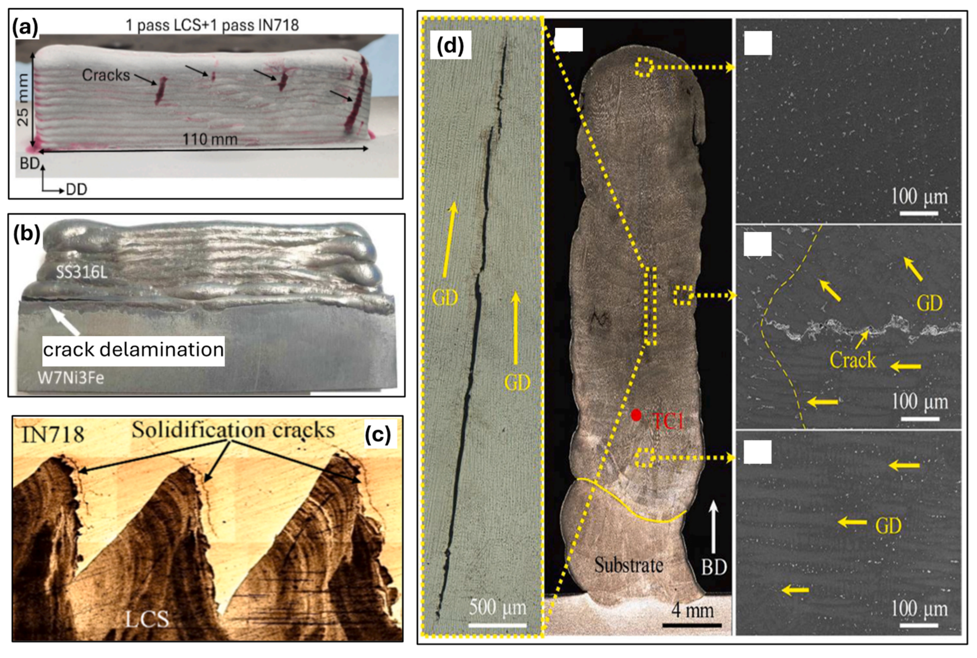
Surface cracks and solidification cracks near the interface on the side of the IN718 were observed in WAAMed IN718-LCS bi-metallic wall fabricated by Bhattacharya et al. [158] as shown in Figure 25a. The origin of these cracks can be attributed to the distinct thermal expansion coefficients of the materials, leading to differing levels of shrinkage during solidification. Multi-material structures of AISI 316L-Ti, W7Ni3Fe-SS316L as depicted in Figure 25b revealed delamination/crack at bimetallic interface, which was attributed to large difference in the coefficient of thermal expansion, thermal conductivity and melting points of these alloys [78]. Delamination defects are often caused by insufficient metallurgical fusion at the interface and resultant poor bonding strength [2]. Figure 25c highlights the presence of solidification cracks at the IN718-LCS bimetallic interface. Another study by Yang et al. [206] demonstrated the significant impact of mixing ratios on crack formation in SS 304L and Inconel 625 FGM. Cracks were observed in the 21% In625 region of sample S3, primarily due to the formation of MC carbides along cellular dendrite boundaries and associated with the solidification mode [206]. In another study by Li et al. [149] on Inconel 625-SS308L FGM fabrication, evidenced cracks located in the middle and upper layers of the specimen and the crack propagated along the grain direction (GD) as depicted in Figure 25d. Strategies such as preheating, stress relief annealing, adaptive thermal control, optimized deposition paths, and balancing wire feed rate with heat input and travel speed can minimize these issues [23,196].

4.3. Material Compatibility Issues and Brittle Intermetallic (IMC) Phase Formation

Material compatibility issues and brittle intermetallic phase formation are another cluster of challenges in wire-DED, especially when dissimilar materials are joined. Bimetal combinations like Al/Cu, Al/Ti, Ni/Ti and Al/Fe are prone to cracking and delamination during WAAM due to significant differences in solubility and reactivity, leading to brittle intermetallic formation. Achieving strong metallurgical bonds between dissimilar alloys is challenging due to differences in composition, microstructure, and thermal properties [83,110,112,128,196]. Even minor alloy composition or processing deviations can severely compromise performance by introducing brittle or deleterious phases. Sharp interfaces between alloys with mismatched properties often lead to residual stress, chemical migration, and premature failure [110,194]. Each alloy pair must be studied individually to determine an optimal joining strategy, and these insights are critical when applying dissimilar metal joining to additive manufacturing. Differences in melting points, crystal lattice, densities, thermal conductivity, and thermal expansion coefficients, as well as diffusion across interfaces, can lead to weak bonding and the formation of brittle intermetallics (e.g., NiAl, FeAl), which reduce toughness and fatigue resistance [13,16].
In the studies by Dhamendra et al. [131,199] on WAAMed NAB/316L BS, SEM and EBSD scans at the NAB/SS interface also clearly revealed the presence of a thin intermetallic layer and occasional HAZ cracks as demonstrated in Figure 26a. The intermetallic layer indicated the Fe3Al-IMC phase. Mishra et al. [110] investigated novel method for fabricating Ti6Al4V and IN718 bimetallic structures using a wire-arc-based directed energy deposition process with a CuSi interlayer, both with and without the addition of pure copper powder at the CuSi–Ti6Al4V interface. EDS analysis confirmed the higher diffusion of Cu towards the Ti-side in the interface without copper powder (IWOP) sample, which results in the formation of three intermetallic layers, i.e., (Zone 1) CuTi + CuTi2, (Zone 2) Cu4Ti3 + Cu3Ti2, and (Zone 3) Cu4Ti3 + Cu3Ti2 as per the atomic composition. However, IWP showed two layers of intermetallic region, i.e., (Zone 1) Cu4Ti3 + Cu3Ti2 and (Zone 2) Cu4Ti + Cu3Ti2. Corresponding IMC layers are depicted in Figure 26b. In another study by Karim et al. [77] IMC, primarily composed of FeAl2Si was observed at the interface of steel/aluminum BS fabricated by CMT-WAAM (Figure 26c). Tensile specimens with high heat input exhibited lower UTS as compared to low heat input specimens, owing to increased IMC thickness due to high heat input.
The following strategies may be applied to address the problem caused by material compatibility issues and brittle intermetallic phase formation.
(a) Introducing buffer layers/transition layer
Joining dissimilar metals can be challenging, especially when they do not mix well. One common method is to use an intermediate bond layer (IBL), which introduces a third metal compatible with two dissimilar. Naiqiang et al. [83] developed the Ti6Al4V/Al6.21Cu bimetallic structure by WAAM based on the cold metal transfer (CMT) technique. They incorporated a Nb interlayer applied via Tungsten Inert Gas (TIG) welding and produced a defect/crack-free structure. The Nb interlayer served as an adequate bonding and diffusion barrier, limiting the interdiffusion of titanium and aluminum atoms and thereby suppressing the formation of brittle Ti-Al intermetallic compounds. In another example Wang et al. [207] developed a crack free Ti-15-3 and 304 titanium alloy via electron beam welding by successful addition of copper transition layer into the weld which results in improvement in the tensile strength with good surface configuration. Similarly, with application of a IN625 interlayer between W7Ni3Fe and SS316L, Karim et al. [78] significantly (1) suppressed the brittle Fe-W IMC phases and (2) reduced the residual stresses by providing a gradual change in the thermal expansion coefficient, resulting in a crack-free, robust W alloy-steel BS.
(b) Thermodynamic analysis using CALPHAD
The phase diagrams derived from experiments and thermodynamic analysis are essential for understanding material behavior under different conditions. The CALPHAD (Calculation of Phase Diagrams) method models the thermodynamic properties of multi-component systems by evaluating Gibbs free energy based on experimental and theoretical data. It is key in predicting phase formation, intermetallic compound development, and solute behavior during additive manufacturing processes like wire-DED, LDED, and L-PBF. By enabling precise phase equilibrium and non-equilibrium calculations, CALPHAD helps design material transitions that avoid harmful intermetallics and optimize process parameters such as cooling rates and temperature, supporting advanced material and process development [208].

4.4. Modeling and Simulation Challenges

Modeling wire-based DED for BS and FGMs poses significant challenges due to processing dissimilar materials with diverse thermophysical properties. Key issues include accurately predicting thermal history, which influences melt pool behavior, solidification, and residual stresses. However, reliable thermophysical property data for high-temperature behavior of multi-component systems is often lacking, hindering simulation accuracy. Challenges intensify in bimetallic systems (e.g., Al/Cu, Ti/Fe) due to sharp thermal mismatches and intermetallic formation, complicating real-time simulation of grain structure, diffusion, and phase transformation. Addressing these complexities demands advanced multi-scale simulation frameworks and enhanced databases for material properties [208].

4.5. Process Control and Automation

Effective process control and automation are critical for achieving defect-free fabrication in wire-DED, especially when dealing with bimetallic structures and FGMs. These applications introduce additional complexity due to abrupt or gradual transitions in material composition, each with distinct melting behaviors, thermal conductivities, and solidification characteristics. Uncontrolled variations in parameters such as wire feed rate, travel speed, torch height, and power input can result in poor interfacial bonding, cracking, composition segregation, and inconsistent layer geometry. This is particularly problematic at dissimilar material interfaces, where even slight deviations can exacerbate thermal stress and intermetallic formation [100].
Modern WAAM systems increasingly incorporate automated deposition path planning and real-time process monitoring using sensors (e.g., thermal cameras, pyrometers, melt pool imaging) to address this. These inputs can be linked to adaptive control algorithms, often driven by machine learning, that dynamically adjust process parameters based on feedback during fabrication [208]. Such closed-loop systems enable consistent thermal management, smoother composition gradients, and enhanced structural integrity. Moreover, multi-material toolpath generation and precise wire switching or blending control are essential to maintaining composition accuracy and avoiding mixing defects in FGMs. As WAAM scales up for industrial bimetallic applications, integrated control architectures combining hardware automation, real-time data analytics, and AI-based predictive models will be vital for ensuring quality, repeatability, and process scalability.

5. Future Directions

WAAM has demonstrated significant potential for fabricating multi-material structures, particularly bimetallic and functionally graded structures. Despite its advantages, several scientific and engineering challenges persist, limiting the full-scale adoption of WAAM for high-performance applications [23]. Addressing these challenges requires a multi-faceted approach encompassing material innovations, process control enhancements, computational modeling, and expanded application domains. This section outlines key future directions for advancing WAAM based multi-material manufacturing [33].

5.1. Development of Advanced Wire Feedstock Materials

The compatibility of dissimilar materials in WAAM remains a critical concern due to the formation of brittle intermetallic phases and residual stress accumulation [17]. The upcoming research will focus on wire innovation and its impact on multi-material component manufacture and characteristics [176]. Future studies should focus on:
  • Designing novel wire compositions: Tailored feedstock materials with optimized elemental composition can mitigate issues related to phase segregation and metallurgical incompatibility.
  • Development of functionally graded wires: Pre-alloyed or gradient-layered wire feedstock can provide controlled transitions between dissimilar materials, reducing sharp material property variations.
  • Incorporation of nanoparticle reinforcements: Dispersion of nanoparticles in metal feedstock can enhance mechanical performance, improve wear resistance, and modify thermal conductivity properties.

5.2. In Situ Monitoring and Adaptive Process Control

Ensuring process stability and repeatability is paramount for high-quality multi-material structures. It would be helpful to researchers for a better understanding of changes in mechanical behavior and microstructure during the AM process. The integration of smart monitoring systems and adaptive control strategies will be essential [209]:
  • Real-time defect detection: Optical and infrared sensors, coupled with machine learning algorithms, can continuously monitor temperature gradients, porosity formation, and phase transformations.
  • Closed-loop control systems: AI-driven process adjustments based on real-time data can optimize deposition parameters, reducing defects and ensuring metallurgical integrity.
  • Advanced thermal management techniques: Utilizing localized heating or cooling mechanisms to control thermal cycling can minimize residual stress and prevent intermetallic brittleness.

5.3. Computational Modeling and Simulation Approaches

Accurate prediction of microstructural evolution, mechanical performance, and residual stress in WAAM-fabricated multi-material structures require advanced simulation techniques [210]. Channeling the capabilities of artificial intelligence, machine learning, and computational modeling can provide a significant boost to optimizing and regulating the WAAM process, improving repeatability, precision, and dependability. However, this will necessitate the availability of huge, structured datasets, the creation of robust models that account for process physics, model validation under changing conditions, and real-time integration with WAAM systems. Addressing these important problems through broad multidisciplinary research will be vital to realizing the multi-material AM’s enormous promise and expanding its applications across critical industries.
  • CALPHAD-based thermodynamic modeling: Predicting phase formation and stability at multi-material interfaces can guide alloy selection and processing conditions.
  • Finite Element Analysis for residual stress prediction: Computational simulations can help us understand stress distributions and optimize deposition strategies.
  • Multiphysics simulation for heat and mass transfer: Combining computational fluid dynamics (CFD) with solidification modeling can provide insights into material flow and thermal history during the WAAM process.

5.4. Process Optimization for Enhanced Microstructure and Mechanical Properties

It is still difficult to precisely optimize the many interdependent process parameters (such as wire feed rate, travel speed, arc current, arc voltage, torch angle, and orientation). Finding the best combinations to provide the required mechanical properties, microstructural features, residual stress, geometric correctness, and surface quality is challenging due to this complicated parameter space. While empirical mapping is widely utilized, it requires a significant investment of time and resources. Advanced computer techniques such as artificial neural networks, Bayesian optimization, and hybrid models hold promises for rapid process optimization. However, the reliability and generalizability of these data-driven approaches must be improved through rigorous model validation. Developing adaptive control systems for real-time automated process correction is also a growing field. To enhance the reliability of WAAM-fabricated structures, further research is needed on optimizing deposition strategies:
  • Gradient optimization algorithms: Machine learning-based models can determine optimal composition transition profiles for functionally graded structures.
  • Residual stress and distortion management: The high heating and cooling rates associated with DED processes, along with mismatch in thermal conductivity and thermal coefficient of expansion of materials used for multi-material structures, result in residual stresses, cracking, and distortion. Preheating and post-processing techniques, such as heat treatment, hot isostatic pressing (HIP) can assist in alleviating some of these issues. However, developing in-process control and mitigation approaches through optimal deposition path design, adaptive process parameters, and filler material selection is critical. This reduces the need for costly post-processing. Advanced multi-physics modeling of thermo-mechanical interactions is critical for understanding the fundamental causes of residual stress and distortions.
  • Exploration of Multi-field Assisted wire-arc additive manufacturing: Existing studies have confirmed that arc additive manufacturing with the introduction of energy field-assisted technology can effectively suppress porosity defects and agglomeration of ceramic particles in the preparation of metal matrix composites [211]. Research on introduction of magnetic field, ultrasonic vibration (UV), laser, and deformation field in energy field-assisted WAAM needs to be explored and improved further to mitigate the microstructural defects and to enhance the mechanical properties of WAAMed multi-material structures.

5.5. Standardization

Currently, the lack of globally approved industry-level standards and requirements for WAAM has slowed its maturity and widespread adoption. A comprehensive database consisting of material properties (chemical composition, melting point, thermal conductivity, specific heat capacity, etc.), material compatibility, WAAM process parameters (heat input, travel speed, wire feed rate, layer thickness, inter pass temperature, etc.), and printed multi-material part performance (strength, ductility, fatigue life, wear resistance, corrosion resistance, etc.) can be established for training machine learning models [212]. These models can thereafter be utilized to conjecture the performance of new multi-material structures. Comprehensive standards must be developed in areas such as feedstock qualification, process monitoring, quality assurance, testing procedures, data formats, part qualification, and operator certification. This will allow for a more consistent comparison of research, quality control across vendors and systems, and compliance with safety-critical applications. Collaboration among industry, academics, and standards groups is critical in this area.

5.6. Expanding Application Scope and Industrial Adoption

Though WAAM for multi-material processing has gained traction in aerospace, automotive, and marine industries, its potential in other sectors remains underexplored:
  • Renewable energy applications: WAAMed multi-material structures can enable the development of high-performance wind turbine components, hydrogen storage systems, and nuclear reactor components.
  • Defense and space exploration: Functionally graded armor systems, propulsion components, and lightweight structural elements can benefit from WAAM’s scalability and material flexibility.
  • Biomedical and healthcare innovations: Multi-material WAAM has the potential to produce customized implants, prosthetics, and bioactive scaffolds for tissue engineering.

6. Conclusions

This review presents a comprehensive overview of the recent progress in the development of metallic multi-material structures fabricated using WAAM. Key aspects such as interfacial microstructure, mechanical properties, fabrication challenges, and future directions have been reviewed in detail.
  • WAAM has emerged as a promising technique for producing bimetallic structures and functionally graded materials using various material combinations, including low carbon steel/stainless steel, stainless steel/maraging steel, steel/copper and copper alloys, steel/aluminum and aluminum alloys, steel/nickel alloys, steel/NAB, titanium/aluminum alloys, nickel/titanium alloys, and refractory alloy/steel or Inconel systems. Among these, materials such as low carbon steel, SS316L, Inconel 625, Inconel 718, and Ti-6Al-4V are most commonly used in WAAM-based multi-material fabrication.
  • Studies have demonstrated that WAAM can produce BS and FGMs with defect-free interfaces, robust interfacial bonding, and tailorable mechanical properties, which is particularly advantageous for high tech engineering applications. However, their performance and integrity are significantly influenced by the mismatch in thermophysical properties (e.g., thermal conductivity, melting point), metallurgical characteristics (e.g., crystal structure), and elastic moduli between dissimilar materials. Addressing these issues is critical to achieving high-quality and durable structures for demanding applications.
  • Despite the many advantages of WAAM, several challenges remain unresolved. Common defects such as cracks, delamination, intermetallic formation, residual stresses, and porosity must be carefully mitigated. In-depth studies are still needed to understand the fundamental mechanisms of defect formation and to develop effective post-processing strategies. Mitigating these problems requires precise control of process parameters, use of interlayers, thermodynamic modeling (e.g., CALPHAD), and advanced real-time process monitoring and automation for reliable, defect-free builds.
  • To unlock the full potential of WAAM for multi-material fabrication, future research should focus on the development of advanced wire materials, integration of in situ monitoring systems, and optimization of process parameters. Additionally, the use of computational modeling, multi-physics simulation, and artificial intelligence (AI) or machine learning (ML) techniques will be essential for predicting microstructure and mechanical properties and enhancing quality, repeatability, and scalability of multi-material structures The establishment of comprehensive global standards will be indispensable for the widespread industrial adoption of multi-material WAAM in sectors such as renewable energy, defense, and biomedical engineering.

Author Contributions

Conceptualization, S.J., S.K., A.B., S.D., A.M., M.C., M.M., S.A. and D.K.; Methodology, S.J., S.K., A.B., S.D., A.M., M.C., M.M., S.A. and D.K.; Investigation, writing—original draft preparation, S.J., S.K., A.B., S.D., A.M., M.C., M.M., S.A. and D.K.; Writing—Review and editing, S.J., S.K., A.B., S.D., A.M., M.C., M.M., S.A. and D.K.; Visualization, S.J.; Supervision, S.J., D.K.; Project administration, D.K.; Funding acquisition, D.K. All authors have read and agreed to the published version of the manuscript.

Funding

This research received no external funding.

Data Availability Statement

The specifics of the literature review data can be provided upon request.

Conflicts of Interest

Author Muralimohan Cheepu was employed by the company Vitzronextech Co., Ltd. The remaining authors declare that the research was conducted in the absence of any commercial or financial relationships that could be construed as a potential conflict of interest.

References

  1. Wei, C.; Zhang, Z.; Cheng, D.; Sun, Z.; Zhu, M.; Li, L. An overview of laser-based multiple metallic material additive manufacturing: From macro- to micro-scales. Int. J. Extrem. Manuf. 2020, 3, 012003. [Google Scholar] [CrossRef]
  2. Wang, D.; Liu, L.; Deng, G.; Deng, C.; Bai, Y.; Yang, Y.; Wu, W.; Chen, J.; Liu, Y.; Wang, Y.; et al. Recent progress on additive manufacturing of multi-material structures with laser powder bed fusion. Virtual Phys. Prototyp. 2022, 17, 329–365. [Google Scholar] [CrossRef]
  3. Wits, W.W.; Amsterdam, E. Graded structures by multi-material mixing in laser powder bed fusion. CIRP Ann. 2021, 70, 159–162. [Google Scholar] [CrossRef]
  4. Chen, P.-Y.; Novitskaya, E.; Lopez, M.I.; Sun, C.-Y.; McKittrick, J. Toward a better understanding of mineral microstructure in bony tissues. Bioinspired Biomim. Nanobiomater. 2014, 3, 71–84. [Google Scholar] [CrossRef]
  5. Katti, K.S.; Katti, D.R.; Mohanty, B. Biomimetic Lessons Learnt from Nacre. In Biomimetics Learning from Nature; IntechOpen Limited: London, UK, 2010; ISBN 978-953-307-025-4. [Google Scholar] [CrossRef]
  6. Cui, Y.; Li, J.; Yim, S.; Yamanaka, K.; Aoyagi, K.; Wang, H.; Chiba, A. Multi-material additive manufacturing of steel/Al alloy by controlling the liquid/solid interface in laser beam powder bed fusion. Addit. Manuf. 2024, 96, 104529. [Google Scholar] [CrossRef]
  7. Tisza, M.; Czinege, I. Comparative study of the application of steels and aluminium in lightweight production of automotive parts. Int. J. Lightweight Mater. Manuf. 2018, 1, 229–238. [Google Scholar] [CrossRef]
  8. Niinomi, M. Mechanical biocompatibilities of titanium alloys for biomedical applications. J. Mech. Behav. Biomed. Mater. 2008, 1, 30–42. [Google Scholar] [CrossRef] [PubMed]
  9. Liu, Z.; Ma, R.; Xu, G.; Wang, W.; Liu, J. Laser additive manufacturing of bimetallic structure from Ti-6Al-4V to Ti-48Al-2Cr-2Nb via vanadium interlayer. Mater. Lett. 2020, 263, 127210. [Google Scholar] [CrossRef]
  10. Gradl, P.R.; Protz, C.S. Technology advancements for channel wall nozzle manufacturing in liquid rocket engines. Acta Astronaut. 2020, 174, 148–158. [Google Scholar] [CrossRef]
  11. Feng, Z. Managed by UT-Battelle for the Department of Energy Multi-Material Joining Challenges and Opportunities; Oak Ridge National Laboratory: Oak Ridge, TN, USA, 2012.
  12. Nazir, A.; Gokcekaya, O.; Billah, K.M.M.; Ertugrul, O.; Jiang, J.; Sun, J.; Hussain, S. Multi-material additive manufacturing: A systematic review of design, properties, applications, challenges, and 3D printing of materials and cellular metamaterials. Mater. Des. 2023, 226, 111661. [Google Scholar] [CrossRef]
  13. Bandyopadhyay, A.; Zhang, Y.; Onuike, B. Additive manufacturing of bimetallic structures. Virtual Phys. Prototyp. 2022, 17, 256–294. [Google Scholar] [CrossRef]
  14. Ghanavati, R.; Naffakh-Moosavy, H. Additive manufacturing of functionally graded metallic materials: A review of experimental and numerical studies. J. Mater. Res. Technol. 2021, 13, 1628–1664. [Google Scholar] [CrossRef]
  15. Sanjeeviprakash, K.; Kannan, A.R.; Shanmugam, N.S. Additive manufacturing of metal-based functionally graded materials: Overview, recent advancements and challenges. J. Braz. Soc. Mech. Sci. Eng. 2023, 45, 1–35. [Google Scholar] [CrossRef]
  16. Reichardt, A.; Shapiro, A.A.; Otis, R.; Dillon, R.P.; Borgonia, J.P.; McEnerney, B.W.; Hosemann, P.; Beese, A.M. Advances in additive manufacturing of metal-based functionally graded materials. Int. Mater. Rev. 2021, 66, 1–29. [Google Scholar] [CrossRef]
  17. Feenstra, D.; Banerjee, R.; Fraser, H.; Huang, A.; Molotnikov, A.; Birbilis, N. Critical review of the state of the art in multi-material fabrication via directed energy deposition. Curr. Opin. Solid State Mater. Sci. 2021, 25, 100924. [Google Scholar] [CrossRef]
  18. Meltio. 2025. Available online: https://meltio3d.com/applications/ (accessed on 20 June 2025).
  19. Zhang, B.; Jaiswal, P.; Rai, R.; Nelaturi, S. Additive Manufacturing of Functionally Graded Material Objects: A Review. J. Comput. Inf. Sci. Eng. 2018, 18, 138209. [Google Scholar] [CrossRef]
  20. Yan, L.; Chen, Y.; Liou, F. Additive manufacturing of functionally graded metallic materials using laser metal deposition. Addit. Manuf. 2020, 31, 100901. [Google Scholar] [CrossRef]
  21. Owoputi, A.O.; Inambao, F.L.; Ebhota, W.S. A Review of Functionally Graded Materials: Fabrication Processes and Applications. Int. J. Appl. Eng. Res. 2018, 13, 16141–16151. [Google Scholar]
  22. Hasanov, S.; Alkunte, S.; Rajeshirke, M.; Gupta, A.; Huseynov, O.; Fidan, I.; Alifui-Segbaya, F.; Rennie, A. Review on additive manufacturing of multi-material parts: Progress and challenges. J. Manuf. Mater. Process. 2022, 6, 4. [Google Scholar] [CrossRef]
  23. Dhanola, A.; Prasad, D.S. A comprehensive review of wire arc additive manufacturing for metallic functionally graded materials. Eng. Res. Express 2024, 6, 042501. [Google Scholar] [CrossRef]
  24. Scheinpflug, J.; Pfeiffenberger, M.; Damerau, A.; Schwarz, F.; Textor, M.; Lang, A.; Schulze, F. Journey into bone models: A review. Genes 2018, 9, 247. [Google Scholar] [CrossRef]
  25. Li, Y.; Feng, Z.; Hao, L.; Huang, L.; Xin, C.; Wang, Y.; Bilotti, E.; Essa, K.; Zhang, H.; Li, Z.; et al. A Review on Functionally Graded Materials and Structures via Additive Manufacturing: From Multi--Scale Design to Versatile Functional Properties. Adv. Mater. Technol. 2020, 5, 1900981. [Google Scholar] [CrossRef]
  26. Mannan, S.; Knox, J.P.; Basu, S. Correlations between axial stiffness and microstructure of a species of bamboo. R. Soc. Open Sci. 2017, 4, 160412. [Google Scholar] [CrossRef] [PubMed]
  27. MedlinePlus Medical Encyclopedia Image, Tooth Anatomy. Available online: https://medlineplus.gov/ency/imagepages/1121.htm (accessed on 9 January 2025).
  28. Teacher, M.; Velu, R. Additive Manufacturing of Functionally Graded Materials: A Comprehensive Review. Int. J. Precis. Eng. Manuf. 2023, 25, 165–197. [Google Scholar] [CrossRef]
  29. Liu, Z.; Meyers, M.A.; Zhang, Z.; Ritchie, R.O. Functional gradients and heterogeneities in biological materials: Design principles, functions, and bioinspired applications. Prog. Mater. Sci. 2017, 88, 467–498. [Google Scholar] [CrossRef]
  30. Silva, R.F.; Coelho, P.G.; Gustavo, C.V.; Almeida, C.J.; Farias, F.W.C.; Duarte, V.R.; Xavier, J.; Esteves, M.B.; Conde, F.M.; Cunha, F.G.; et al. Functionally Graded Materials and Structures: Unified Approach by Optimal Design, Metal Additive Manufacturing, and Image-Based Characterization. Materials 2024, 17, 4545. [Google Scholar] [CrossRef]
  31. Alkunte, S.; Fidan, I.; Naikwadi, V.; Gudavasov, S.; Ali, M.A.; Mahmudov, M.; Hasanov, S.; Cheepu, M. Advancements and Challenges in Additively Manufactured Functionally Graded Materials: A Comprehensive Review. J. Manuf. Mater. Process. 2024, 8, 23. [Google Scholar] [CrossRef]
  32. Saleh, B.; Jiang, J.; Fathi, R.; Al-Hababi, T.; Xu, Q.; Wang, L.; Song, D.; Ma, A. 30 Years of functionally graded materials: An overview of manufacturing methods, Applications and Future Challenges. Compos. Part B Eng. 2020, 201, 108376. [Google Scholar] [CrossRef]
  33. Hamrani, A.; Bouarab, F.Z.; Agarwal, A.; Ju, K.; Akbarzadeh, H. Advancements and applications of multiple wire processes in additive manufacturing: A comprehensive systematic review. Virtual Phys. Prototyp. 2023, 18, e2273303. [Google Scholar] [CrossRef]
  34. Verma, A.; Kapil, A.; Klobčar, D.; Sharma, A. A Review on Multiplicity in Multi-Material Additive Manufacturing: Process, Capability, Scale, and Structure. Materials 2023, 16, 5246. [Google Scholar] [CrossRef]
  35. Zhang, C.; Yu, H.; Sun, D.; Liu, W. Fabrication of Multi-Material Components by Wire Arc Additive Manufacturing. Coatings 2022, 12, 1683. [Google Scholar] [CrossRef]
  36. Page, M.J.; McKenzie, J.E.; Bossuyt, P.M.; Boutron, I.; Hoffmann, T.C.; Mulrow, C.D.; Shamseer, L.; Tetzlaff, J.M.; Akl, E.A.; Brennan, S.E.; et al. The PRISMA 2020 statement: An updated guideline for reporting systematic reviews. BMJ 2021, 372, n71. [Google Scholar] [CrossRef]
  37. Donthu, N.; Kumar, S.; Mukherjee, D.; Pandey, N.; Lim, W.M. How to conduct a bibliometric analysis: An overview and guidelines. J. Bus. Res. 2021, 133, 285–296. [Google Scholar] [CrossRef]
  38. Kusekar, S.K.; Pirani, M.; Birajdar, V.D.; Borkar, T.; Farahani, S. Toward the Progression of Sustainable Structural Batteries: State-of-the-Art Review. SAE Int. J. Sustain. Transp. Energy Environ. Policy 2025, 5. [Google Scholar] [CrossRef]
  39. Bandyopadhyay, A.; Heer, B. Additive manufacturing of multi-material structures. Mater. Sci. Eng. R Rep. 2018, 129, 1–16. [Google Scholar] [CrossRef]
  40. Tian, X.; Zhao, Z.; Wang, H.; Liu, X.; Song, X. Progresses on the additive manufacturing of functionally graded metallic materials. J. Alloys Compd. 2023, 960, 170687. [Google Scholar] [CrossRef]
  41. Wei, C.; Li, L. Recent progress and scientific challenges in multi-material additive manufacturing via laser-based powder bed fusion. Virtual Phys. Prototyp. 2021, 16, 347–371. [Google Scholar] [CrossRef]
  42. Jiang, W.; Guan, F.; Li, G.; Jiang, H.; Zhu, J.; Fan, Z. Processing of Al/Cu bimetal via a novel compound casting method. Mater. Manuf. Process. 2019, 34, 1016–1025. [Google Scholar] [CrossRef]
  43. Rogachev, S.O.; Andreev, V.A.; Yusupov, V.S.; Bondareva, S.A.; Khatkevich, V.M.; Nikolaev, E.V. Effect of Rotary Forging on Microstructure Evolution and Mechanical Properties of Aluminum Alloy/Copper Bimetallic Material. Met. Mater. Int. 2022, 28, 1038–1046. [Google Scholar] [CrossRef]
  44. Sun, Z.; Karppi, R. The application of electron beam welding for the joining of dissimilar metals: An overview. J. Mater. Process. Technol. 1996, 59, 257–267. [Google Scholar] [CrossRef]
  45. Chen, H.-C.; Pinkerton, A.J.; Li, L. Fibre laser welding of dissimilar alloys of Ti-6Al-4V and Inconel 718 for aerospace applications. Int. J. Adv. Manuf. Technol. 2011, 52, 977–987. [Google Scholar] [CrossRef]
  46. Chu, Q.; Zhang, M.; Li, J.; Yan, C. Experimental and numerical investigation of microstructure and mechanical behavior of titanium/steel interfaces prepared by explosive welding. Mater. Sci. Eng. A 2017, 689, 323–331. [Google Scholar] [CrossRef]
  47. Razzaq, S.; Pan, Z.; Li, H.; Ringer, S.; Liao, X. Joining dissimilar metals by additive manufacturing: A review. J. Mater. Res. Technol. 2024, 31, 2820–2845. [Google Scholar] [CrossRef]
  48. Fazel-Najafabadi, M.; Kashani-Bozorg, S.; Zarei-Hanzaki, A. Joining of CP-Ti to 304 stainless steel using friction stir welding technique. Mater. Des. 2010, 31, 4800–4807. [Google Scholar] [CrossRef]
  49. Celik, S.; Cakir, R. Effect of Friction Stir Welding Parameters on the Mechanical and Microstructure Properties of the Al-Cu Butt Joint. Metals 2016, 6, 133. [Google Scholar] [CrossRef]
  50. Feng, J.; Songbai, X.; Wei, D. Reliability studies of Cu/Al joints brazed with Zn–Al–Ce filler metals. Mater. Des. 2012, 42, 156–163. [Google Scholar] [CrossRef]
  51. Hong, I.-T.; Koo, C.-H. Microstructural evolution and shear strength of brazing C103 and Ti–6Al–4V using Ti–20Cu–20Ni–20Zr (wt.%) filler metal. Int. J. Refract. Met. Hard Mater. 2006, 24, 247–252. [Google Scholar] [CrossRef]
  52. Guo, Y.; Liu, G.; Jin, H.; Shi, Z.; Qiao, G. Intermetallic phase formation in diffusion-bonded Cu/Al laminates. J. Mater. Sci. 2011, 46, 2467–2473. [Google Scholar] [CrossRef]
  53. Elrefaey, A.; Tillmann, W. Solid state diffusion bonding of titanium to steel using a copper base alloy as interlayer. J. Mech. Work. Technol. 2009, 209, 2746–2752. [Google Scholar] [CrossRef]
  54. Zakipour, S.; Halvaee, A.; Amadeh, A.A.; Samavatian, M.; Khodabandeh, A. An investigation on microstructure evolution and mechanical properties during transient liquid phase bonding of stainless steel 316L to Ti–6Al–4V. J. Alloys Compd. 2015, 626, 269–276. [Google Scholar] [CrossRef]
  55. Norouzi, E.; Atapour, M.; Shamanian, M.; Allafchian, A. Effect of bonding temperature on the microstructure and mechanical properties of Ti-6Al-4V to AISI 304 transient liquid phase bonded joint. Mater. Des. 2016, 99, 543–551. [Google Scholar] [CrossRef]
  56. Martinsen, K.; Hu, S.; Carlson, B. Joining of dissimilar materials. CIRP Ann. 2015, 64, 679–699. [Google Scholar] [CrossRef]
  57. Naebe, M.; Shirvanimoghaddam, K. Functionally graded materials: A review of fabrication and properties. Appl. Mater. Today 2016, 5, 223–245. [Google Scholar] [CrossRef]
  58. Bergmann, C.P.; Modupe, R.; Esther, M.; Akinlabi, T. Topics in Mining, Metallurgy and Materials Engineering Series Editor: Functionally Graded Materials. Available online: http://www.springer.com/series/11054 (accessed on 22 May 2025).
  59. Zhang, C.; Chen, F.; Huang, Z.; Jia, M.; Chen, G.; Ye, Y.; Lin, Y.; Liu, W.; Chen, B.; Shen, Q.; et al. Additive manufacturing of functionally graded materials: A review. Mater. Sci. Eng. A 2019, 764, 138209. [Google Scholar] [CrossRef]
  60. Kieback, B.; Neubrand, A.; Riedel, H. Processing techniques for functionally graded materials. Mater. Sci. Eng. A 2003, 362, 81–106. [Google Scholar] [CrossRef]
  61. ISO/ASTM 52900:2017; Additive Manufacturing—General Principles—Terminology. ASTM International/International Organization for Standardization: Geneva, Switzerland, 2017.
  62. Attaran, M. The rise of 3-D printing: The advantages of additive manufacturing over traditional manufacturing. Bus. Horiz. 2017, 60, 677–688. [Google Scholar] [CrossRef]
  63. Blakey-Milner, B.; Gradl, P.; Snedden, G.; Brooks, M.; Pitot, J.; Lopez, E.; Leary, M.; Berto, F.; du Plessis, A. Metal additive manufacturing in aerospace: A review. Mater. Des. 2021, 209, 110008. [Google Scholar] [CrossRef]
  64. Vafadar, A.; Guzzomi, F.; Rassau, A.; Hayward, K. Advances in metal additive manufacturing: A review of common processes, industrial applications, and current challenges. Appl. Sci. 2021, 11, 1213. [Google Scholar] [CrossRef]
  65. Sampaio, R.; Pragana, J.; Bragança, I.; Silva, C.; Nielsen, C.; Martins, P. Modelling of wire-arc additive manufacturing—A review. Adv. Ind. Manuf. Eng. 2023, 6, 100121. [Google Scholar] [CrossRef]
  66. Özel, T.; Shokri, H.; Loizeau, R. A Review on Wire-Fed Directed Energy Deposition Based Metal Additive Manufacturing. J. Manuf. Mater. Process. 2023, 7, 45. [Google Scholar] [CrossRef]
  67. Costello, S.C.; Cunningham, C.R.; Xu, F.; Shokrani, A.; Dhokia, V.; Newman, S.T. The state-of-the-art of wire arc directed energy deposition (WA-DED) as an additive manufacturing process for large metallic component manufacture. Int. J. Comput. Integr. Manuf. 2023, 36, 469–510. [Google Scholar] [CrossRef]
  68. Abuabiah, M.; Mbodj, N.G.; Shaqour, B.; Herzallah, L.; Juaidi, A.; Abdallah, R.; Plapper, P. Advancements in Laser Wire-Feed Metal Additive Manufacturing: A Brief Review. Materials 2023, 16, 2030. [Google Scholar] [CrossRef]
  69. Osipovich, K.; Kalashnikov, K.; Chumaevskii, A.; Gurianov, D.; Kalashnikova, T.; Vorontsov, A.; Zykova, A.; Utyaganova, V.; Panfilov, A.; Nikolaeva, A.; et al. Wire-Feed Electron Beam Additive Manufacturing: A Review. Metals 2023, 13, 279. [Google Scholar] [CrossRef]
  70. Wu, B.; Pan, Z.; Ding, D.; Cuiuri, D.; Li, H.; Xu, J.; Norrish, J. A review of the wire arc additive manufacturing of metals: Properties, defects and quality improvement. J. Manuf. Process. 2018, 35, 127–139. [Google Scholar] [CrossRef]
  71. Shah, A.; Aliyev, R.; Zeidler, H.; Krinke, S. A Review of the Recent Developments and Challenges in Wire Arc Additive Manufacturing (WAAM) Process. J. Manuf. Mater. Process. 2023, 7, 97. [Google Scholar] [CrossRef]
  72. Moschinger, M.; Vauderwange, T.; Enzinger, N. Plasma wire arc additive manufacturing and its influence on high-carbon steel substrate properties. Weld. World 2024, 68, 1999–2011. [Google Scholar] [CrossRef]
  73. Srivastava, M.; Rathee, S.; Tiwari, A.; Dongre, M. Wire arc additive manufacturing of metals: A review on processes, materials and their behaviour. Mater. Chem. Phys. 2023, 294, 126988. [Google Scholar] [CrossRef]
  74. Xia, C.; Pan, Z.; Polden, J.; Li, H.; Xu, Y.; Chen, S.; Zhang, Y. A review on wire arc additive manufacturing: Monitoring, control and a framework of automated system. J. Manuf. Syst. 2020, 57, 31–45. [Google Scholar] [CrossRef]
  75. Jadhav, S.; Karim, A.; Kim, D.B. Bimetallic structure of TZM and NbZr1 fabricated by wire-based directed energy deposition. Mater. Lett. 2024, 356, 135605. [Google Scholar] [CrossRef]
  76. Jadhav, S.; Tanvir, G.; Karim, A.; Islam, S.; Noh, S.D.; Kim, D.B. Microstructures and mechanical behaviour of bimetallic structures of tungsten alloy (90WNiFe) and nickel alloy (In625) fabricated by wire-arc directed energy deposition. Virtual Phys. Prototyp. 2024, 19, e2370957. [Google Scholar] [CrossRef]
  77. Karim, A.; Jadhav, S.; Kannan, R.; Pierce, D.; Lee, Y.; Nandwana, P.; Kim, D.B. Investigating stainless steel/aluminum bimetallic structures fabricated by cold metal transfer (CMT)-based wire-arc directed energy deposition. Addit. Manuf. 2024, 81, 104015. [Google Scholar] [CrossRef]
  78. Karim, A.; Islam, S.; Tanvir, G.; Jadhav, S.; Kim, Y.-M.; Jeon, Y.; Kim, D.B. Wire-arc directed energy deposition of steel onto tungsten substrate: Fabricability and mechanical performance of synergistic structures. Virtual Phys. Prototyp. 2025, 20, e2443578. [Google Scholar] [CrossRef]
  79. Jadhav, S.; Bajestani, M.S.; Islam, S.; Karim, A.; Kim, C.J.; Lee, H.-J.; Cho, Y.T.; Kim, D.B. Materials characterization of Ti6Al4V to NbZr1 bimetallic structure fabricated by wire arc additive manufacturing. Mater. Today Commun. 2023, 36, 106934. [Google Scholar] [CrossRef]
  80. Kannan, R.; Pierce, D.; Nayir, S.; Ahsan, R.U.; Kim, D.; Unocic, K.; Lee, Y.; Jadhav, S.; Karim, A.; Nandwana, P. Wire directed energy deposition of steel-aluminum structures using cold metal transfer process. J. Mater. Res. Technol. 2024, 29, 4537–4546. [Google Scholar] [CrossRef]
  81. Du, X.; Wei, Y.; Guo, K.; Long, J.; Liu, X.; Zhao, W.; Liu, R. Interface microstructure and evolution mechanism of wire arc additively manufactured H13 steel-copper hybrid components. J. Mater. Res. Technol. 2025, 35, 4929–4944. [Google Scholar] [CrossRef]
  82. Zhang, W.; Lei, Y.; Meng, W.; Ma, Q.; Yin, X.; Guo, L. Effect of Deposition Sequence on Microstructure and Properties of 316L and Inconel 625 Bimetallic Structure by Wire Arc Additive Manufacturing. J. Mater. Eng. Perform. 2021, 30, 8972–8983. [Google Scholar] [CrossRef]
  83. Xu, N.; Shen, J.; Hu, S.; Tian, Y.; Bi, J. Bimetallic structure of Ti6Al4V and Al6.21Cu fabricated by cold metal transfer additive manufacturing via Nb interlayer added by TIG. Mater. Lett. 2021, 302, 130397. [Google Scholar] [CrossRef]
  84. Munusamy, S.; Jerald, J. Effect of build orientation on the microstructure and mechanical properties of wire arc additive manufactured grade 91 steel/monel 400 bimetallic components. Vacuum 2024, 227, 113429. [Google Scholar] [CrossRef]
  85. Tian, Y.; Shen, J.; Hu, S.; Gou, J.; Cui, Y. Effects of cold metal transfer mode on the reaction layer of wire and arc additive-manufactured Ti-6Al-4V/Al-6.25Cu dissimilar alloys. J. Mater. Sci. Technol. 2021, 74, 35–45. [Google Scholar] [CrossRef]
  86. Raut, L.P.; Taiwade, R.V. Microstructure and Mechanical Properties of Wire Arc Additively Manufactured Bimetallic Structure of Austenitic Stainless Steel and Low Carbon Steel. J. Mater. Eng. Perform. 2022, 31, 8531–8541. [Google Scholar] [CrossRef]
  87. Squires, L.; Roberts, E.; Bandyopadhyay, A. Radial bimetallic structures via wire arc directed energy deposition-based additive manufacturing. Nat. Commun. 2023, 14, 3544. [Google Scholar] [CrossRef]
  88. Wu, B.; Qiu, Z.; Pan, Z.; Carpenter, K.; Wang, T.; Ding, D.; Van Duin, S.; Li, H. Enhanced interface strength in steel-nickel bimetallic component fabricated using wire arc additive manufacturing with interweaving deposition strategy. J. Mater. Sci. Technol. 2020, 52, 226–234. [Google Scholar] [CrossRef]
  89. Marefat, F.; Kapil, A.; Banaee, S.A.; Van Rymenant, P.; Sharma, A. Evaluating shielding gas-filler wire interaction in bi-metallic wire arc additive manufacturing (WAAM) of creep resistant steel-stainless steel for improved process stability and build quality. J. Manuf. Process. 2023, 88, 110–124. [Google Scholar] [CrossRef]
  90. Ozaner, O.C.; Klobčar, D.; Sharma, A. Machining Strategy Determination for Single- and Multi-Material Wire and Arc Additive Manufactured Thin-Walled Parts. Materials 2023, 16, 2055. [Google Scholar] [CrossRef] [PubMed]
  91. Suárez, A.; Panfilo, A.; Aldalur, E.; Veiga, F.; Gomez, P. Microstructure and mechanical properties of mild steel-stainless steel bimetallic structures built using Wire Arc Additive Manufacturing. CIRP J. Manuf. Sci. Technol. 2022, 38, 769–773. [Google Scholar] [CrossRef]
  92. Marefat, F.; De Pauw, J.; Kapil, A.; Chernovol, N.; Van Rymenant, P.; Sharma, A. Design strategies for bi-metallic additive manufacturing in the context of wire and arc directed energy deposition. Mater. Des. 2022, 215, 110496. [Google Scholar] [CrossRef]
  93. Pattanayak, S.; Sahoo, S.K.; Sahoo, A.K. An approach to tunable advanced high-strength steel fabrication through multi-wire arc additive manufacturing (M-WAAM). J. Manuf. Process. 2025, 133, 705–722. [Google Scholar] [CrossRef]
  94. Zhai, W.; Guo, Y.; Aishwarya; Canturri, C.; Shandro, R.; Zhou, W. Wire arc additive manufacturing of ER70S-6/S355 bimetal component. Mater. Sci. Eng. A 2024, 900, 146498. [Google Scholar] [CrossRef]
  95. Yadav, A.; Srivastava, M.; Jain, P.K. Design and fabrication of wire arc additive manufacturing setup and enhanced tailored properties of dissimilar steel additively deposited by WAAM process. Structures 2025, 72, 108228. [Google Scholar] [CrossRef]
  96. Kumar, A.; Maji, K.; Samanta, A. Fabrication and characterization of austenite-ferrite stainless steel bimetals by twin wire arc additive manufacturing. J. Adhes. Sci. Technol. 2024, 39, 708–733. [Google Scholar] [CrossRef]
  97. Thirugnanasambandam, A.; Subramaniyan, M.K.; Elumalai, V. Fabrication of Bimetallic Structure (SS 316L/SS 308L) via Wire + Arc Additive Manufacturing: A Detailed Characterization of Interface. J. Mater. Eng. Perform. 2025, 34, 16297–16308. [Google Scholar] [CrossRef]
  98. Singh, S.; Jinoop, A.; Palani, I.; Paul, C.; Tomar, K.; Prashanth, K. Microstructure and mechanical properties of NiTi-SS bimetallic structures built using Wire Arc Additive Manufacturing. Mater. Lett. 2021, 303, 130499. [Google Scholar] [CrossRef]
  99. Aslam, M.; Sahoo, C.K. Development of hard and wear-resistant SiC-AISI304 stainless steel clad layer on low carbon steel by GMAW process. Mater. Today Commun. 2023, 36, 106444. [Google Scholar] [CrossRef]
  100. Gürol, U.; Turgut, B.; Güleçyüz, N.; DİLİBAL, S.; Koçak, M. Development of Multi-Material Components Via Robotic Wire Arc additive Manufacturing. Int. J. 3D Print. Technol. Digit. Ind. 2021, 5, 721–729. [Google Scholar] [CrossRef]
  101. Badoniya, P.; Srivastava, M.; Jain, P.K. Microstructural Characteristics and Mechanical Performance of WAAM Fabricated LCS–SS 316L Bimetallic Structure Under Forced Cooling. J. Mater. Eng. Perform. 2025, 1–15. [Google Scholar] [CrossRef]
  102. Tyagi, S.; Balla, S.K.; Manjaiah, M.; Aranas, C. Microstructure and mechanical properties of stainless steel 316L-Inconel 625 bimetallic structure fabricated by laser wire direct energy deposition. J. Mater. Res. Technol. 2024, 33, 8361–8371. [Google Scholar] [CrossRef]
  103. Ahsan, R.; Fan, X.; Seo, G.-J.; Ji, C.; Noakes, M.; Nycz, A.; Liaw, P.K.; Kim, D.B. Microstructures and mechanical behavior of the bimetallic additively-manufactured structure (BAMS) of austenitic stainless steel and Inconel 625. J. Mater. Sci. Technol. 2021, 74, 176–188. [Google Scholar] [CrossRef]
  104. Wu, B.; Shi, H.; Liu, J.; Zhang, B.; Zhou, T.; Pan, Z.; Li, H. Selective crack propagation in steel-nickel component printed by wire arc directed energy deposition. Mater. Des. 2024, 237, 112541. [Google Scholar] [CrossRef]
  105. Kumar, A.; Maji, K. Microstructure and Chemical Composition Analysis of Double Wire Arc Additive Manufactured Bimetallic Structure. J. Mater. Eng. Perform. 2021, 30, 5413–5425. [Google Scholar] [CrossRef]
  106. Sridar, S.; Klecka, M.A.; Xiong, W. Interfacial characteristics of P91 steel—Inconel 740H bimetallic structure fabricated using wire-arc additive manufacturing. J. Mech. Work. Technol. 2022, 300, 117396. [Google Scholar] [CrossRef]
  107. Hwang, Y.-H.; Lee, C.-M.; Kim, D.-H. The Effects of the Variable-Pressure Rolling of a Wire Arc Additively Manufactured Inconel625-SS308L Bimetallic Structure. Appl. Sci. 2023, 13, 10187. [Google Scholar] [CrossRef]
  108. Zhang, M.; Zhang, Y.; Du, M.; Zhang, S.; Lei, L. Experimental Characterization and Microstructural Evaluation of Silicon Bronze-Alloy Steel Bimetallic Structures by Additive Manufacturing. Met. Mater. Trans. A 2021, 52, 4664–4674. [Google Scholar] [CrossRef]
  109. Liu, J.; Miao, Y.; Wang, Z.; Zhao, Y.; Wu, Y.; Li, C. Improved interfacial strength in bimetallic additive manufacturing of aluminum bronze/steel by controlling interface melting. J. Manuf. Process. 2024, 121, 333–342. [Google Scholar] [CrossRef]
  110. Mishra, A.; Paul, A.R.; Mukherjee, M.; Singh, R.K. Bimetallic Structure of Ti6Al4V/IN718 with CuSi Interlayer for Wire-Arc Directed Energy Deposition Process. Met. Mater. Int. 2023, 29, 2331–2344. [Google Scholar] [CrossRef]
  111. Cai, X.; Wang, Z.; Dong, L.; Yang, M.; Zhou, J.; Xue, F. Advanced mechanical properties of nickel--aluminum bronze/steel composite structure prepared by wire--arc additive manufacturing. Mater. Des. 2022, 221, 110969. [Google Scholar] [CrossRef]
  112. Singh, S.; Demidova, E.; Resnina, N.; Belyaev, S.; Iyamperumal, P.A.; Paul, C.P.; Prashanth, K.G. NiTi–Cu Bimetallic Structure Fabrication through Wire Arc Additive Manufacturing. Materials 2024, 17, 1006. [Google Scholar] [CrossRef]
  113. Tomar, B.; Shiva, S. Microstructure evolution in steel/copper graded deposition prepared using wire arc additive manufacturing. Mater. Lett. 2022, 328, 133217. [Google Scholar] [CrossRef]
  114. Chen, L.; Oliveira, J.P.; Yan, X.; Pang, B.; Ke, W.; Shen, J.; Teshome, F.B.; Schell, N.; Zhou, N.; Peng, B.; et al. Microstructure and Phase Transformation Behavior of NiTiCu Shape Memory Alloys Produced Using Twin-Wire Arc Additive Manufacturing. Addit. Manuf. Front. 2024, 3, 200132. [Google Scholar] [CrossRef]
  115. Munusamy, S.; Jerald, J. Impact of Laser Shock Peening on Mechanical Properties of Wire Arc Additive Manufactured Grade 91 Steel and Monel-400 Bimetallic Components. Met. Mater. Int. 2024, 31, 36–48. [Google Scholar] [CrossRef]
  116. Tian, Y.; Shen, J.; Hu, S.; Chen, X.; Cai, Y.; Han, J. Effect of deposition layer on microstructure of Ti–Al bimetallic structures fabricated by wire and arc additive manufacturing. Sci. Technol. Weld. Join. 2022, 27, 22–32. [Google Scholar] [CrossRef]
  117. Xia, Y.; Zhang, X.; Chen, L.; Jiang, X.; Liao, H. Deformation Characteristics and Mechanical Properties of Ti/Al Bimetallic Composite Materials Fabricated by Wire Plus Arc Additive Manufacturing. J. Wuhan Univ. Technol. Sci. Ed. 2023, 38, 885–892. [Google Scholar] [CrossRef]
  118. Ozlati, A.; Movahedi, M.; Ramezani, H. Wire arc additive manufacturing of stainless steel/aluminum bi-metal using roll-bonded transition joint. Manuf. Lett. 2025, 43, 6–11. [Google Scholar] [CrossRef]
  119. Liu, J.; Miao, Y.; Wang, Z.; Zhao, Y.; Wu, Y.; Li, C. Effect of heat treatment on microstructure and properties of additively manufactured aluminum bronze-steel bimetallic structures. Mater. Charact. 2024, 207, 113462. [Google Scholar] [CrossRef]
  120. Tanvir, G.; Karim, A.; Jadhav, S.; Islam, S.; Kim, Y.-M.; Ryu, H.J.; Kim, D.B. Effect of hot isostatic pressing on porosity of wire-arc directed energy deposited TZM/NbZr1 bimetallic structure. Virtual Phys. Prototyp. 2024, 19, e2404989. [Google Scholar] [CrossRef]
  121. Hauser, T.; Reisch, R.T.; Seebauer, S.; Parasar, A.; Kamps, T.; Casati, R.; Volpp, J.; Kaplan, A.F. Multi-Material Wire Arc Additive Manufacturing of low and high alloyed aluminium alloys with in-situ material analysis. J. Manuf. Process. 2021, 69, 378–390. [Google Scholar] [CrossRef]
  122. Azar, A.S.; Lekatou, A.; Sunding, M.F.; Graff, J.S.; Tzima, N.; Diplas, S. Corrosion performance and degradation mechanism of a bi-metallic aluminum structure processed by wire-arc additive manufacturing. NPJ Mater. Degrad. 2021, 5, 1–15. [Google Scholar] [CrossRef]
  123. Han, S.; Zhang, Z.; Liu, Z.; Zhang, H.; Xue, D. Investigation of the microstructure and mechanical performance of bimetal components fabricated using CMT-based wire arc additive manufacturing. Mater. Res. Express 2020, 7, 116525. [Google Scholar] [CrossRef]
  124. Motwani, A.; Kumar, A.; Puri, Y.; Lautre, N.K. Mechanical characteristics and microstructural investigation of CMT deposited bimetallic SS316LSi-IN625 thin wall for WAAM. Weld. World 2023, 67, 967–980. [Google Scholar] [CrossRef]
  125. Mahmoudiniya, M.; Thorr, A.-S.; Petrov, R.H.; Hermans, M.J.; Kestens, L.A. Wire arc additive manufacturing of Ni Fe alloy/ductile cast iron bimetallic structure; phase transformations, microstructure and crystallographic texture. Mater. Charact. 2025, 220, 114650. [Google Scholar] [CrossRef]
  126. He, T.; Yu, S.; Runzhen, Y.; Bo, Z. Oscillating wire arc additive manufacture of rocket motor bimetallic conical shell. Int. J. Adv. Manuf. Technol. 2022, 119, 6601–6612. [Google Scholar] [CrossRef]
  127. Tomar, B.; Shiva, S. Analysis of AISI 316L-Ti Graded Deposition Fabricated by Wire and Arc Additive Manufacturing. Trans. Indian Inst. Met. 2024, 77, 279–285. [Google Scholar] [CrossRef]
  128. Abe, T.; Sasahara, H. Dissimilar metal deposition with a stainless steel and nickel-based alloy using wire and arc-based additive manufacturing. Precis. Eng. 2016, 45, 387–395. [Google Scholar] [CrossRef]
  129. Gürol, U.; Turgut, B.; Kumek, H.; Dilibal, S.; Koçak, M. Fabrication and Characterization of Wire Arc Additively Manufactured Ferritic-Austenitic Bimetallic Structure. Met. Mater. Int. 2024, 30, 1342–1355. [Google Scholar] [CrossRef]
  130. Gürol, U.; DİLİBAL, S.; Turgut, B.; Baykal, H.; Kümek, H.; Koçak, M. Manufacturing and characterizaton of waam-based bimetallic cutting tool. Int. J. 3D Print. Technol. Digit. Ind. 2022, 6, 548–555. [Google Scholar] [CrossRef]
  131. Dharmendra, C.; Shakerin, S.; Ram, G.J.; Mohammadi, M. Wire-arc additive manufacturing of nickel aluminum bronze/stainless steel hybrid parts—Interfacial characterization, prospects, and problems. Materialia 2020, 13, 100834. [Google Scholar] [CrossRef]
  132. Rani, K.U.; Kumar, R.; Mahapatra, M.M.; Mulik, R.S.; Świerczyńska, A.; Fydrych, D.; Pandey, C. Wire Arc Additive Manufactured Mild Steel and Austenitic Stainless Steel Components: Microstructure, Mechanical Properties and Residual Stresses. Materials 2022, 15, 7094. [Google Scholar] [CrossRef]
  133. Kannan, A.R.; Kumar, S.M.; Pramod, R.; Kumar, N.P.; Shanmugam, N.S.; Palguna, Y. Microstructure and mechanical properties of wire arc additive manufactured bi-metallic structure. Sci. Technol. Weld. Join. 2020, 26, 47–57. [Google Scholar] [CrossRef]
  134. Wang, J.; Pan, Z.; Wang, L.; Su, L.; Carpenter, K.; Wang, J.; Wang, R.; Li, H. In-situ dual wire arc additive manufacturing of NiTi-coating on Ti6Al4V alloys: Microstructure characterization and mechanical properties. Surf. Coat. Technol. 2020, 386, 125439. [Google Scholar] [CrossRef]
  135. Liu, K.; Yan, Z.; Pan, R.; Wang, X.; Wang, F.; Chen, S. Interfacial bonding and microstructural evolution in Inconel-copper bimetallic structures fabricated by directed energy deposition-arc. Mater. Sci. Eng. A 2024, 898, 146381. [Google Scholar] [CrossRef]
  136. Hu, Q.; Wang, X.; Shen, X.; Tan, Z. Microstructure and corrosion resistance in bimetal materials of Q345 and 308 steel wire-arc additive manufacturing. Crystals 2021, 11, 1401. [Google Scholar] [CrossRef]
  137. Wang, Z.; Chen, W.; Xu, J.; Zhu, J.; Ma, Z.; Shi, J.; Zhou, Q. Fabrication of TC4 and Ti48Al bimetals by plasma arc additive manufacturing: Microstructure and mechanical properties. J. Mater. Res. Technol. 2024, 32, 2482–2494. [Google Scholar] [CrossRef]
  138. Segovia-Guerrero, L.; Baladés, N.; Attard, B.; De Nicolás, M.; Scotti, A.; Zammit, A.; Sales, D.L. Multi-material stainless steel fabrication using plasma wire arc additive manufacturing. J. Mater. Res. Technol. 2024, 30, 3996–4002. [Google Scholar] [CrossRef]
  139. Yadav, A.; Srivastava, M.; Jain, P.K.; Rathee, S. Functional behaviour of novel multi-layered deposition via twin wire arc additive manufacturing: Microstructure evolution and wear tailoring characteristics. Structures 2024, 67, 106901. [Google Scholar] [CrossRef]
  140. Han, J.; Lu, L.; Xin, Y.; Chen, X.; Zhang, G.; Cai, Y.; Tian, Y. Microstructure and mechanical properties of a novel functionally graded material from Ti6Al4V to Inconel 625 fabricated by dual wire + arc additive manufacturing. J. Alloys Compd. 2022, 903, 163981. [Google Scholar] [CrossRef]
  141. Lu, L.; Tian, Y.; Cai, Y.; Xin, Y.; Chen, X.; Zhang, G.; Han, J. Microstructure and mechanical properties of a functionally graded material from TA1 to Inconel 625 fabricated by dual wire + arc additive manufacturing. Mater. Lett. 2021, 298, 130010. [Google Scholar] [CrossRef]
  142. Zhang, J.; Li, C.; Yang, X.; Wang, D.; Hu, W.; Di, X.; Zhang, J. In-situ heat treatment (IHT) wire arc additive manufacturing of Inconel625-HSLA steel functionally graded material. Mater. Lett. 2023, 330, 133326. [Google Scholar] [CrossRef]
  143. Zhang, J.; Li, C.; Ba, L.; Di, X. Transition Strategy Optimization of Inconel625-HSLA Steel Functionally Graded Material Fabricated by Wire Arc Additive Manufacturing. Met. Mater. Int. 2023, 29, 767–776. [Google Scholar] [CrossRef]
  144. Jeong, T.-W.; Cho, Y.T.; Lee, C.-M.; Kim, D.-H. Effects of ultrasonic treatment on mechanical properties and microstructure of stainless steel 308L and Inconel 718 functionally graded materials fabricated via double-wire arc additive manufacturing. Mater. Sci. Eng. A 2024, 896, 146298. [Google Scholar] [CrossRef]
  145. Wang, J.; Wang, H.; Xu, T.; Li, Z.; Liu, C. Research on the microstructure and mechanical properties of functional gradient materials of TC4/TC11 titanium alloys for wire arc additive manufacturing with different transitional forms. J. Manuf. Process. 2024, 131, 245–255. [Google Scholar] [CrossRef]
  146. Xin, D.; Yao, X.; Zhang, J.; Chen, X. Fabrication of functionally graded material of 304L stainless steel and Inconel625 by twin-wire plasma arc additive manufacturing. J. Mater. Res. Technol. 2023, 23, 4135–4147. [Google Scholar] [CrossRef]
  147. Ayan, Y.; Kahraman, N. Fabrication and characterization of functionally graded material (FGM) structure containing two dissimilar steels (ER70S-6 and 308LSi) by wire arc additive manufacturing (WAAM). Mater. Today Commun. 2022, 33, 104457. [Google Scholar] [CrossRef]
  148. Yadav, A.; Srivastava, M.; Jain, P.K.; Rathee, S. Functionally graded deposition of dissimilar steel (316LSi and ER70S-6) fabricated through twin-wire arc additive manufacturing. Mater. Lett. 2024, 354, 135395. [Google Scholar] [CrossRef]
  149. Li, T.; Wang, Z.; Hu, S.; Yang, Z.; Wang, Y. Hot cracking during the fabrication of Inconel 625/stainless steel 308 L functionally graded material by dual-wire arc additive manufacturing. J. Manuf. Process. 2022, 82, 461–473. [Google Scholar] [CrossRef]
  150. Li, T.; Wang, Z.; Yang, Z.; Shu, X.; Xu, J.; Wang, Y.; Hu, S. Fabrication and characterization of stainless steel 308 L/Inconel 625 functionally graded material with continuous change in composition by dual-wire arc additive manufacturing. J. Alloys Compd. 2022, 915, 165398. [Google Scholar] [CrossRef]
  151. Li, T.; Wang, Z.; Yang, Z.; Wang, Y.; Hu, S. Effect of Different Wire Feeding Strategies on the Preparation of Functionally Graded Materials by Dual-Wire Arc Additive Manufacturing. Met. Mater. Trans. B 2023, 54, 43–49. [Google Scholar] [CrossRef]
  152. Pütz, R.D.; Pratesa, Y.; Oster, L.; Sharma, R.; Reisgen, U.; Zander, D. Microstructure and Corrosion Behavior of Functionally Graded Wire Arc Additive Manufactured Steel Combinations. Steel Res. Int. 2021, 92, 2100387. [Google Scholar] [CrossRef]
  153. Li, T.; Wang, Z.; Yang, Z.; Wang, Y. Strengthening the functionally graded material of stainless steel 308L and Inconel 625 by local Nb alloying. Mater. Lett. 2023, 331, 133499. [Google Scholar] [CrossRef]
  154. Reisgen, U.; Sharma, R.; Oster, L. Plasma Multiwire technology with alternating wire feed for tailor-made material properties in wire and arc additive manufacturing. Metals 2019, 9, 745. [Google Scholar] [CrossRef]
  155. Zhu, Q.; Yu, X.; Yao, P.; Yue, Y.; Kang, G. Study on Optimization Strategy for the Composition Transition Gradient in SS 316L/Inconel 625 Functionally Graded Materials. Materials 2024, 17, 2910. [Google Scholar] [CrossRef]
  156. Yadav, A.; Srivastava, M.; Jain, P.K.; Rathee, S. Microstructure and tribological behaviour of dissimilar steel functional structure developed via arc-based DED process. Tribol. Int. 2024, 197, 109782. [Google Scholar] [CrossRef]
  157. Tirupataiah, K.; Kiran, D.V.; Venkaiah, N. Iron aluminide FGM thin wall fabrication using CMT-based twin wire arc additive manufacturing process. Mater. Lett. 2023, 349, 134836. [Google Scholar] [CrossRef]
  158. Bhattacharya, A.; Banaee, S.A.; Sharma, M.; Kapil, A.; Sharma, A. IN718-LCS bi-metallic deposition by wire arc additive manufacturing: Issues, mitigation strategies, and interfacial behavior. J. Manuf. Process. 2025, 140, 204–223. [Google Scholar] [CrossRef]
  159. Khan, A.U.; Sadhya, S.; Kumar, A.B.; Chatterjee, S.; Madhukar, Y.K. Investigation on dual wire TIG Arc additive manufacturing of IN625 and SS316L FGM for continuous gradient and sandwich structures. Thin-Walled Struct. 2024, 200, 111881. [Google Scholar] [CrossRef]
  160. Shen, C.; Pan, Z.; Cuiuri, D.; Roberts, J.; Li, H. Fabrication of Fe-FeAl Functionally Graded Material Using the Wire-Arc Additive Manufacturing Process. Met. Mater. Trans. B 2016, 47, 763–772. [Google Scholar] [CrossRef]
  161. Huang, J.; Liu, G.; Yu, X.; Guan, Z.; Yu, S.; Fan, D. Characterization of nickel-titanium alloy graded materials using double wire alternating current cross arc additive manufacturing. J. Alloys Compd. 2022, 910, 164912. [Google Scholar] [CrossRef]
  162. Wang, J.; Pan, Z.; Ma, Y.; Lu, Y.; Shen, C.; Cuiuri, D.; Li, H. Characterization of wire arc additively manufactured titanium aluminide functionally graded material: Microstructure, mechanical properties and oxidation behaviour. Mater. Sci. Eng. A 2018, 734, 110–119. [Google Scholar] [CrossRef]
  163. Wang, J.; Wang, H.; Xu, T.; Liu, C. Different compositions of TC4/TC11 functional gradient materials interface by wire arc additive manufacturing. Sci. China Technol. Sci. 2024, 67, 3777–3782. [Google Scholar] [CrossRef]
  164. Yu, X.; Xue, J.; Shen, Q.; Zheng, Z.; Ou, N.; Wu, W. Dual-Wire Plasma Arc Additively Manufactured SS 316L-Inconel 625 Functionally Graded Material: Microstructure Evolution and Mechanical Properties. J. Mater. Eng. Perform. 2023, 32, 1412–1422. [Google Scholar] [CrossRef]
  165. Miao, Y.; Li, C.; Zhao, Y.; Wu, Y.; Liu, J.; Wang, Z.; Zhang, B. Material properties of gradient copper--nickel alloy fabricated by wire arc additive manufacturing based on bypass-current PAW. J. Manuf. Process. 2022, 83, 637–649. [Google Scholar] [CrossRef]
  166. Huang, J.; Liu, G.; Yu, X.; Wu, H.; Huang, Y.; Yu, S.; Fan, D. Microstructure regulation of titanium alloy functionally gradient materials fabricated by alternating current assisted wire arc additive manufacturing. Mater. Des. 2022, 218, 110731. [Google Scholar] [CrossRef]
  167. Shen, C.; Liss, K.-D.; Reid, M.; Pan, Z.; Hua, X.; Li, F.; Mou, G.; Huang, Y.; Dong, B.; Luo, D.; et al. Effect of the post-production heat treatment on phase evolution in the Fe3Ni–FeNi functionally graded material: An in-situ neutron diffraction study. Intermetallics 2021, 129, 107032. [Google Scholar] [CrossRef]
  168. Jiang, P.; Nie, M.; Teng, J.; Wang, X.; Liu, C.; Zhang, Z. Multi-wire arc additive manufacturing of TC4/Nb bionic layered heterogeneous alloy: Microstructure evolution and mechanical properties. Mater. Sci. Eng. A 2023, 874, 145076. [Google Scholar] [CrossRef]
  169. Xiang, R.; Huang, J.; Yu, X.; Zhao, H.; Song, X.; Fan, D. The effect of Ni/Ti atomic ratios on residual stress and deformation in WAAM of dissimilar filler wire NiTi alloys. J. Mater. Res. Technol. 2025, 35, 1813–1828. [Google Scholar] [CrossRef]
  170. Rodrigues, T.A.; Bairrão, N.; Farias, F.W.C.; Shamsolhodaei, A.; Shen, J.; Zhou, N.; Maawad, E.; Schell, N.; Santos, T.G.; Oliveira, J. Steel-copper functionally graded material produced by twin-wire and arc additive manufacturing (T-WAAM). Mater. Des. 2022, 213, 110270. [Google Scholar] [CrossRef]
  171. Li, Z.; Chang, B.; Cui, Y.; Zhang, H.; Liang, Z.; Liu, C.; Wang, L.; Du, D.; Chang, S. Effect of twin-wire feeding methods on the in-situ synthesis of electron beam fabricated Ti-Al-Nb intermetallics. Mater. Des. 2022, 215, 110509. [Google Scholar] [CrossRef]
  172. Zhang, W.; Wang, J.; Zhu, X.; Lu, X.; Ling, X. A functionally graded material from stainless steel 304 to Fe–40Al fabricated by dual wire arc additive manufacturing. J. Mater. Res. Technol. 2024, 28, 3566–3572. [Google Scholar] [CrossRef]
  173. Tomar, B.; Shiva, S. Microstructural and mechanical properties examination of SS316L-Cu functionally graded material fabricated by wire arc additive manufacturing. CIRP J. Manuf. Sci. Technol. 2024, 50, 26–39. [Google Scholar] [CrossRef]
  174. Ju, Y.; Li, C.; Yang, X.; Ba, L.; Wang, Y.; Di, X. Recent progress on additive manufacturing of steel-based functionally graded materials. Mater. Today Commun. 2024, 40, 109953. [Google Scholar] [CrossRef]
  175. Adinarayanappa, S.M.; Simhambhatla, S. Twin-wire welding based additive manufacturing (TWAM): Manufacture of functionally gradient objects. Rapid Prototyp. J. 2017, 23, 858–868. [Google Scholar] [CrossRef]
  176. Yi, H.; Jia, L.; Ding, J.; Li, H. Achieving material diversity in wire arc additive manufacturing: Leaping from alloys to composites via wire innovation. Int. J. Mach. Tools Manuf. 2024, 194, 104103. [Google Scholar] [CrossRef]
  177. Senthil, T.S.; Babu, S.R.; Puviyarasan, M. Mechanical, microstructural and fracture studies on inconel 825–SS316L functionally graded wall fabricated by wire arc additive manufacturing. Sci. Rep. 2023, 13, 1–14. [Google Scholar] [CrossRef]
  178. Kumar, S.M.; Kannan, A.R.; Kumar, N.P.; Pramod, R.; Shanmugam, N.S.; Vishnu, A.S.; Channabasavanna, S.G. Microstructural Features and Mechanical Integrity of Wire Arc Additive Manufactured SS321/Inconel 625 Functionally Gradient Material. J. Mater. Eng. Perform. 2021, 30, 5692–5703. [Google Scholar] [CrossRef]
  179. Amiri, V.; Naffakh-Moosavy, H. Wire arc additive manufacturing of functionally graded carbon steel—Stainless steel 316L—Inconel 625: Microstructural characterization and mechanical behavior. J. Adv. Join. Process. 2024, 9, 100194. [Google Scholar] [CrossRef]
  180. Singh, M.; Singh, R.K.R.; Gupta, D. Metallurgical and mechanical properties of trimetallic functionally graded material fabricated by wire arc additive manufacturing. J. Alloys Compd. 2024, 1004, 175725. [Google Scholar] [CrossRef]
  181. Kannan, A.R.; Kumar, S.M.; Kumar, N.P.; Shanmugam, N.S.; Vishnu, A.; Palguna, Y. Process-microstructural features for tailoring fatigue strength of wire arc additive manufactured functionally graded material of SS904L and Hastelloy C-276. Mater. Lett. 2020, 274, 127968. [Google Scholar] [CrossRef]
  182. Muthu, S.; Prabu, S.S.; Sujai, S.; Sebastian, J.; Liyakat, N.A. Microstructure and mechanical properties of functionally graded materials alloy 82/AISI 304L by employing WAAM. Mater. Today Commun. 2025, 42, 111399. [Google Scholar] [CrossRef]
  183. Senthil, T.; Babu, S.R.; Puviyarasan, M.; Dhinakaran, V. Mechanical and microstructural characterization of functionally graded Inconel 825—SS316L fabricated using wire arc additive manufacturing. J. Mater. Res. Technol. 2021, 15, 661–669. [Google Scholar] [CrossRef]
  184. Sainath, K.; Prabagaran, S.; Soundararajan, R. A Comparison Study on Detailed Strengthening mechanism analysis on micro structure and mechanical properties of 3 phases FGM Material with vibrational behavior analysis is fabricated using WAAM process and traditional method. J. Alloys Compd. 2024, 1003, 175543. [Google Scholar] [CrossRef]
  185. Senthil, T.; Puviyarasan, M.; Babu, S.R.; Prabhu, T.R. Pitting corrosion studies on functionally graded Inconel 825-SS316L wall manufactured by wire arc additive manufacturing. Eng. Res. Express 2022, 4, 035013. [Google Scholar] [CrossRef]
  186. Veeman, D.; Alruqi, M.; Subramaniyan, M.K.; Nallathambhi, S.S.; Browne, M.A.; Kamaraj, A. Fabrication of functionally graded material via gas tungsten arc welding based wire feeding additive manufacturing: Mechanical and microstructural characterization. Mater. Lett. 2022, 324, 132786. [Google Scholar] [CrossRef]
  187. Chen, X.; Han, J.; Wang, J.; Cai, Y.; Zhang, G.; Lu, L.; Xin, Y.; Tian, Y. A functionally graded material from TC4 to 316L stainless steel fabricated by double-wire + arc additive manufacturing. Mater. Lett. 2021, 300, 130141. [Google Scholar] [CrossRef]
  188. Han, J.; Meng, M.; Liu, H.; Jiang, Z.; Zhao, X.; Xu, Y.; Tian, Y.; Zhang, X. Microstructure and mechanical properties of Ti-6Al-4V/Ni-Ti functionally graded material fabricated by multi-wire arc additive manufacturing. Sci. Technol. Weld. Join. 2024, 29, 232–241. [Google Scholar] [CrossRef]
  189. Marinelli, G.; Martina, F.; Lewtas, H.; Hancock, D.; Ganguly, S.; Williams, S. Functionally graded structures of refractory metals by wire arc additive manufacturing. Sci. Technol. Weld. Join. 2019, 24, 495–503. [Google Scholar] [CrossRef]
  190. Chandrasekaran, S.; Hari, S.; Amirthalingam, M. Functionally graded materials for marine risers by additive manufacturing for high-temperature applications: Experimental investigations. Structures 2022, 35, 931–938. [Google Scholar] [CrossRef]
  191. Wang, Y.; Konovalov, S.; Chen, X.; Singh, R.A.; Jayalakshmi, S. Research on plasma arc additive manufacturing of Inconel 625 Ni–Cu functionally graded materials. Mater. Sci. Eng. A 2022, 853, 143796. [Google Scholar] [CrossRef]
  192. Shen, C.; Hua, X.; Reid, M.; Liss, K.-D.; Mou, G.; Pan, Z.; Huang, Y.; Li, H. Thermal induced phase evolution of Fe–Fe3Ni functionally graded material fabricated using the wire-arc additive manufacturing process: An in-situ neutron diffraction study. J. Alloys Compd. 2020, 826, 154097. [Google Scholar] [CrossRef]
  193. Singh, M.; Singh, R.K.R.; Gupta, D. Investigation of Frictional Deformation on Mechanical and Metallurgical Properties of Ni-based Functionally Graded Materials Developed by Wire and Arc Additive Manufacturing. J. Mater. Eng. Perform. 2024, 34, 1112–1122. [Google Scholar] [CrossRef]
  194. Bobbio, L.D.; Bocklund, B.; Reichardt, A.; Otis, R.; Borgonia, J.P.; Dillon, R.P.; Shapiro, A.A.; McEnerney, B.W.; Hosemann, P.; Liu, Z.-K.; et al. Analysis of formation and growth of the σ phase in additively manufactured functionally graded materials. J. Alloys Compd. 2020, 814, 151729. [Google Scholar] [CrossRef]
  195. Chen, X.; Kong, F.; Fu, Y.; Zhao, X.; Li, R.; Wang, G.; Zhang, H. A review on wire-arc additive manufacturing: Typical defects, detection approaches, and multisensor data fusion-based model. Int. J. Adv. Manuf. Technol. 2021, 117, 707–727. [Google Scholar] [CrossRef]
  196. Zhang, X.; Sun, C.; Pan, T.; Flood, A.; Zhang, Y.; Li, L.; Liou, F. Additive manufacturing of copper—H13 tool steel bi-metallic structures via Ni-based multi-interlayer. Addit. Manuf. 2020, 36, 101474. [Google Scholar] [CrossRef]
  197. Osipovich, K.; Vorontsov, A.; Chumaevskii, A.; Gurianov, D.; Shamarin, N.; Savchenko, N.; Kolubaev, E. Characterization of a bimetallic multilayered composite “stainless steel/copper” fabricated with wire-feed electron beam additive manufacturing. Metals 2021, 11, 1151. [Google Scholar] [CrossRef]
  198. Ghanavati, R.; Naffakh-Moosavy, H.; Moradi, M.; Gadalińska, E.; Saboori, A. Residual stresses and distortion in additively-manufactured SS316L-IN718 multi-material by laser-directed energy deposition: A validated numerical-statistical approach. J. Manuf. Process. 2023, 108, 292–309. [Google Scholar] [CrossRef]
  199. Dharmendra, C.; Shakerin, S.; Mohammadi, M. Metallurgical Assessment of Additive Manufactured Nickel Aluminum Bronze-316L Stainless Steel Bimetallic Structure: Effect of Deposit Geometry on the Interfacial Characteristics and Cracking. J. Mater. Eng. Perform. 2021, 30, 8746–8762. [Google Scholar] [CrossRef]
  200. Hauser, T.; Reisch, R.T.; Breese, P.P.; Lutz, B.S.; Pantano, M.; Nalam, Y.; Bela, K.; Kamps, T.; Volpp, J.; Kaplan, A.F.H. Porosity in wire arc additive manufacturing of aluminium alloys. Addit. Manuf. 2021, 41, 101993. [Google Scholar] [CrossRef]
  201. Zhang, W.; Yi, H.; He, H.; Cao, H. Content effects of in-situ synthesis TiC for grain refinement, porosity suppression and performance enhancement in wire arc additive manufactured Al-Cu alloy. J. Mech. Work. Technol. 2025, 340, 118875. [Google Scholar] [CrossRef]
  202. Treutler, K.; Wesling, V. The current state of research of wire arc additive manufacturing (Waam): A review. Appl. Sci. 2021, 11, 8619. [Google Scholar] [CrossRef]
  203. Mukherjee, T.; Zhang, W.; DebRoy, T. An improved prediction of residual stresses and distortion in additive manufacturing. Comput. Mater. Sci. 2017, 126, 360–372. [Google Scholar] [CrossRef]
  204. Ahmad, B.; Zhang, X.; Guo, H.; Fitzpatrick, M.E.; Neto, L.M.S.C.; Williams, S. Influence of Deposition Strategies on Residual Stress in Wire + Arc Additive Manufactured Titanium Ti-6Al-4V. Metals 2022, 12, 253. [Google Scholar] [CrossRef]
  205. Wu, Q.; Mukherjee, T.; De, A.; DebRoy, T. Residual stresses in wire-arc additive manufacturing—Hierarchy of influential variables. Addit. Manuf. 2020, 35, 101355. [Google Scholar] [CrossRef]
  206. Yang, Z.; Sun, H.; Shang, S.L.; Liu, Z.K.; Beese, A.M. Effect of heat treatment on functionally graded 304L stainless steel to Inconel 625 fabricated by directed energy deposition. Materialia 2024, 34, 102067. [Google Scholar] [CrossRef]
  207. Wang, T.; Zhang, B.-G.; Chen, G.-Q.; Feng, J.-C.; Tang, Q. Electron beam welding of Ti-15-3 titanium alloy to 304 stainless steel with copper interlayer sheet. Trans. Nonferrous Met. Soc. China 2010, 20, 1829–1834. [Google Scholar] [CrossRef]
  208. Alkunte, S.; Gupta, M.; Rajeshirke, M.; More, N.; Cheepu, M.; Gupta, A.; Lakal, N.; Shingare, K.; Alifui-Segbaya, F.; Fidan, I. Functionally Graded Metamaterials: Fabrication Techniques, Modeling, and Applications—A Review. Processes 2024, 12, 2252. [Google Scholar] [CrossRef]
  209. Mattera, G.; Nele, L.; Paolella, D. Monitoring and control the Wire Arc Additive Manufacturing process using artificial intelligence techniques: A review. J. Intell. Manuf. 2024, 35, 467–497. [Google Scholar] [CrossRef]
  210. Chen, Z.; Yuan, L.; Pan, Z.; Zhu, H.; Ma, N.; Ding, D.; Li, H. A comprehensive review and future perspectives of simulation approaches in wire arc additive manufacturing (WAAM). Int. J. Extrem. Manuf. 2025, 7, 022016. [Google Scholar] [CrossRef]
  211. Yi, H.; Lang, T.; Si, J.; Chi, Y.; Cao, H.; Huang, Y. High-performance manufacturing of metal components via multi-field assisted wire-arc directed energy deposition. J. Manuf. Process. 2025, 143, 234–276. [Google Scholar] [CrossRef]
  212. Chen, Z.; Han, C.; Gao, M.; Kandukuri, S.Y.; Zhou, K. A review on qualification and certification for metal additive manufacturing. Virtual Phys. Prototyp. 2022, 17, 382–405. [Google Scholar] [CrossRef]
Figure 1. Common multi-material structures, Redrawn from [17].
Jmmp 09 00284 g001
Figure 2. Applications of bimetallic Structures (a) Channel wall nozzle [10]. License number (6057781101223). (b) Dual-material combustion chamber, Inconel 718 + Copper [18]. (c) Dual-material Pipe, SS316L + Ni718 [18]. (d) TC4/TiAl BS aero-engine turbine blade [9]. License number (6057791310681).
Jmmp 09 00284 g002
Figure 3. (a) Nature-inspired FGMs [32]. License number (6058251489276); FGMs with different forms of gradient. (b) Discontinuous FGMs with interface. (c) Continuous FGMs with no interface. (d,g) Composition gradient. (e,h) Orientation gradient. (f,i) Fraction gradient [29]. License number (6057800190426). (j) FGM applications adopted from [14]. License number (6058250905879).
Jmmp 09 00284 g003
Figure 4. Number of research articles published yearly on bimetallic structures and functionally graded materials from 2015 to 2025.
Jmmp 09 00284 g004
Figure 5. Network visualization among the keywords in WAAM of bimetallic structures and functionally graded materials studies.
Jmmp 09 00284 g005
Figure 6. The clustering analysis of the proposed Scopus and Web of Science article selections.
Jmmp 09 00284 g006
Figure 7. Classification of metal additive manufacturing (MAM) processes.
Jmmp 09 00284 g007
Figure 8. Wire DED Additive Manufacturing processes: (a) Gas Metal Arc Welding (GMAW), (b) gas tungsten arc welding (GTAW), (c) plasma arc welding (PAW), (d) wire laser additive manufacturing (WLAM) and (e) electron beam freeform fabrication (EBF).
Jmmp 09 00284 g008
Figure 9. Deposition strategies in BS fabrication: (a) material B deposited on the substrate of material A, (b) material B layered over a deposit of material A, (c) radial BS structure, (d) interweaving deposition with multilayers along the Z direction, (e) interweaving deposition with multilayers along both Y and Z directions, and (f) material B deposited on the lateral surface of a material A wall.
Jmmp 09 00284 g009
Figure 10. (a) Side view of the deposited ER70SG–SS316LSi BS wall, (b) microstructure of the top region of SS316LSi, (c) microstructure of the middle region of SS316LSi wall, (d) microstructure of SS316LSi at higher magnification, (e) microstructure of interface of SS316LSi and ER70SG, (f) microstructure of the middle layer of ER70S-G, (g) microstructure of ER70S-G at higher magnification [86]. License Number (6057801410559).
Jmmp 09 00284 g010
Figure 11. Effect of interlayer forced cooling on WAAM-fabricated LCS and SS316L BS: (a) schematic of the cooling-assisted setup, (b,c) deposited block under natural and forced cooling, (d) microstructural results, (e) stress–strain response, and (f) microhardness profile across the bimetallic interface [101]. License Number (6086880638982).
Jmmp 09 00284 g011
Figure 12. Digital Image Correlation (DIC) analysis of the WAAM-fabricated ER70S-6/S355 bimetal joint under tensile loading [94]. License Number (6057820712734).
Jmmp 09 00284 g012
Figure 13. Morphology of as-deposited NiTiCu: (a) Macroscopic morphology of different deposited layers, (b) Cross-section of zone B, Microstructure of (c) Region 1, (d) Region 2, (e) Region 3, (f) Region 4 [114].
Jmmp 09 00284 g013
Figure 14. Numerical simulation framework for WAAM of H13/Cu BS: (ad) meshing strategy for build and substrate, (eh) temperature-dependent thermal and mechanical properties of H13 and Cu, (i) schematic of the double ellipsoidal arc heat source, (j) validation of simulated heat input with actual molten pool geometry [81]. License Number (6057821326171).
Jmmp 09 00284 g014
Figure 15. Micrograph of Ti/Al BS sample (a), Microstructure of sample 2: (b) cross-section of the component, (cg) magnified micrographs of areas A–E highlighted with rectangles in (b), EDS results (i), Schematic of reaction layer formation (jm) [85]. License Number (6057830356591).
Jmmp 09 00284 g015
Figure 16. Fabrication and strengthening mechanism of biomimetic radial bimetallic structures via WAAM (a) arrangement of torch, (b) deposition strategy, (c) Conceptual 3D model for BS, (d) deposited BS, (e) machined and drilled BS, (f) bone structure, (g) illustration exploring the effect of slight CTE differences, (h) compression test results, (i) comparison of compression test results [87].
Jmmp 09 00284 g016
Figure 17. Deposition strategies in FGM fabrication: (a) composition gradient in build direction, (b) composition gradient at transition zone, (c) alternate deposition of materials A and B, (d) composition gradient in torch travel direction. (A, B—wire materials).
Jmmp 09 00284 g017
Figure 18. Arrangement of torches employed for FGM fabrication (a) Single torch, (b) Twin torch, (c) Tandem torch. (A, B—wires of different materials).
Jmmp 09 00284 g018
Figure 19. Wire feeding strategies employed for FGM fabrication (a) left-right layout, (b) up-down layout. (A, B—wires of different materials).
Jmmp 09 00284 g019
Figure 20. (a) D-WAAM system, locations dimensions of the tensile test samples, the appearance of SS308L-In625 FGM wall, (b) SEM images of the FGM from 100 wt% SS308L to 100 wt% IN625 with weight fractions of IN625 marked, (c) microhardness of the FGM with the change in IN625, (d) tensile test results in building direction of the FGM, (e) typical engineering stress–strain curves and the fracture samples, (f) tensile test results in the torch traveling direction of FGM, strain distribution maps of DIC Test, (g) Inverse pole figure (IPF) maps of the FGM from 100 wt% SS308L to 100 wt% IN625, (h) Fracture morphology of the FGM with different contents of IN625 [150]. License Number (6057830874078).
Jmmp 09 00284 g020
Figure 21. (a) Ti-6Al-4V/Ni-Ti FGM wall and Sampling locations of specimens, (b) Microstructure of Ti-6Al-4V/Ni-Ti FGM at different regions, (c) Results of electrochemical corrosion tests: PDP curves, Ecorr and Icorr results, Nyquist plots and equivalent circuit, Bode plots, (d) Optical image of cross-section, Microhardness of as-built wall, Contour map of microhardness, Load-depth curve [188].
Jmmp 09 00284 g021
Figure 22. Compression test results: (a,b) Stress–strain curves of Ni-Ti and gradient region, (c) Cyclic stress–strain curves of Ni-Ti; (d) Accumulated residual strain of Ni-Ti, (e,f) Ni-Ti and gradient region fracture morphology, (g) Elemental distribution of FGM, (h) XRD results of different regions [188].
Jmmp 09 00284 g022
Figure 23. Common challenges in multi-material fabrication using the WAAM process (A, B—wires of different materials) [75,78,83,89,125,158,198,199]. License Number (6057850006509, 6057850234839, 6057850382469, 6057850935807, 6057850511421).
Jmmp 09 00284 g023
Figure 24. (a) Cross-sections of the multi-material wall (CRS-SS) deposited using different shielding gases M12 and M14 [89], (b) Microstructure at TZM-NbZr1 interface with pores [75], (c) Pores at the molybdenum and tungsten interface of Ta-W-Mo FGM [189], (d) Pores in the BS of Cast iron—Ni-Fe alloy [125]. License Number (6057850006509, 6057850234839).
Jmmp 09 00284 g024
Figure 25. (a) Surface cracks in WAAMed IN718-LCS bi-metallic wall [158]. License Number (6057850935807). (b) Delamination/crack at the interface of W7Ni3Fe-SS316L BS [78]. (c) Cracks at the interface of the IN718-LCS BS [158]. License Number (6057850935807). (d) Micrographs showing the cracks observed in Inconel 625-SS308L FGM [149]. License Number 6057860062055).
Jmmp 09 00284 g025
Figure 26. (a) SEM micrographs and EBSD Euler maps of the NAB/316 L BS showing a thin intermetallic layer at the interface [131]. License Number (6057860689494). (b) Microstructure at Cu–Ti interface of Ti6Al4V/IN718 BS showing intermetallic layer [110]. (c) SEM images., EBSD phase maps for Steel/Aluminum BS showing FeAl2Si IMC [77]. License Number (6057861187753).
Jmmp 09 00284 g026
Table 1. Comparison of BS and FGMs.
FeatureBimetallic StructuresFunctionally Graded Materials
InterfaceSharp transitionSmooth transition
Stress DistributionHigh at the interfaceSmooth, gradual
Property tailoringLimitedHighly customizable
Processing complexityLow weld/joinHigh—requires AM/control
Structural integrityInterfacial failure riskBetter bonding
Design FreedomLimited to two layersMulti-gradient possible
Table 2. Pros and cons of WAAM.
FeatureAdvantagesLimitations
Deposition RateHigh deposition rate suitable for large-scale productionLess suitable for fine-featured or intricate geometries
Material UtilizationLow buy-to-fly ratio; minimal material wastageMay require post-processing for surface finish
Heat Input ControlBetter control overheat input compared to powder-based AMThermal cycles can induce residual stresses
Component Size CapabilityCapable of producing large structural componentsLimited resolution and dimensional accuracy
Cost-EffectivenessMore economically feasible for large metal parts and structuresEquipment and skill requirements may be high
Multi-Material FabricationSuccessfully demonstrated for BS and FGMsInterface control and metallurgical bonding challenges
Table 3. Summary of studies on bimetallic structures fabricated using WAAM.
Material SystemAM SystemProcessing ParametersKey FindingsRef.
SS316L/Inconel 625GMAW-WAAM (CMT)Wire diameter: 1.2 mm, Current: 200 A (SS316L), 148 A (In625); Voltage: 13.1 V (SS316L), 14.5 V (In625); Feed rate: 6.5 m/min; Travel speed: 600 mm/minSmooth compositional transition at the interface Microhardness: 240 HV (Interface),
UTS/% Elongation: 600 MPa/40%
[103]
SS316L/Inconel 625GMAW-WAAM (CMT)Wire diameter: 1.2 mm, Current: 85–160 A, Voltage: 16.4–20.0 V (auto-adjusted), Wire Feed Speed: 2.9–5.7 m/min, Travel Speed: 200 mm/minThe interface well bonded with no defects, has plenty of Laves phases rich in Nb, Mo
Microhardness: 240 HV (Interface)
UTS/% Elongation: 406–444 MPa/23–38%
[82]
ER70S-6/SS316LGMAW-WAAM (CMT)Wire Feed Speed: ER70S-6—2 m/min (fixed) and 316L SS—0 to 1.5 m/min, Voltage: 18.5 V, Travel speed: 200 mm/min; Gas: Ar @ 20 L/min; Stand-off: 6 mmMicrostructures comprise ferrite, bainite and martensite phases with the evolution of δ-ferrite
Microhardness ER70S-6: 220 HV
UTS/% Elongation: 1089–1231 MPa/17–22%
[93]
Al-5Mg alloy (AA5083)/Al-6061-T6 plateGMAW-WAAM (CMT)Voltage: 15.3 V, Current: 177 A, Wire Feed Rate: 8 m/min, Travel Speed: 360 mm/minPresence of relatively coarse IMCs Al (Fe, Mn)Si
UTS: 220–250 MPa
Corrosion Behavior, Surface Chemistry, Topography
[122]
TC4 (Ti-6Al-4V)/ER5356 (Al–5Mg)GMAW-WAAM (CMT)Wire Diameter: TC4 (Ti-6Al-4V)—Ø 1.2 mm; ER5356 (Al–5Mg)—Ø 1.2 mm; Wire Feed Speed: TC4—9.1 m/min; ER5356—5.9 m/min.Presence Pores and Ti/Al intermetallic compounds
Hardness: TC4—384.9 HV, ER5356—84.38 HV
UTS/% Elongation: 250–1314 MPa/4.1–8.8%
[117]
Low Carbon Steel (LCS)/SS 316L stainless steelGMAW-WAAM (CMT)Wire Diameter: 1.2 mm; Voltage: 12.8–15 V; Wire Feed Speed (WFS): 4.5–7.5 m/min; Travel Speed (TS): 200–400 mm/min; Interpass Temperature: ~100 °C; Heat Input: ~14.9–41.3 kJ/mmInterface sound and free from defects
Microhardness: LCS Side: ~180–200 HV, SS316L Side: ~220–250 HV, Interface (CTZ): Up to 463 HV
Interfacial shear strength: 140 MPa
[92]
Ti-6Al-4V/Al-6.25CuGMAW-WAAM (CMT)Wire Diameter: 1.2 mm, Feed speed: 7.2 m/min (Ti wire), 4.0 m/min (Al wire); Travel speed: 0.3 m/min, Wire extension: 12 mm,TiAl3, TiAl, and Ti3Al IMCs observed
EDS Morphology, phase composition, intermetallic formation)
[116]
Ti-6Al-4V/Al-6.25CuGMAW-WAAM (CMT)Wire Diameter: 1.2 mm, Wire Feed Speed (WFS): Ti: 7.2 m/min, Al: 4.0 m/min; Travel Speed: 300 mm/min, Torch Distance (CTWD): 12 mmTiAl3 IMCs in DC-CMT mode
TiAl and Ti3Al IMCs in CMT+P mode
Hardness: Lower, smoother hardness gradient (~370 HV)
[85]
ER80S-G and MF6–55GP/Q235 low carbon steelGMAW-WAAM (CMT)Wire Diameter: 1.2 mm, Current: 82 A, Voltage: 12.6 V,
Travel Speed: 300 mm/min, Wire Feed Speed: 5 m/min, Interpass Temperature: 130 °C
No defects at interface
Microhardness: MF6–55GP: Increases from 500 HV (transition zone) to peak 800 HV at 8th layer
UTS: 447.79 MPa, has better stability, wear resistance
[123]
SS316L/ER70S-6 (Low Carbon Steel)GMAW-WAAM (CMT)Wire Diameter: 1.0 mm, Current: SS316L—70 A, ER70S-6—80 A; Voltage: SS316L—17.8 V, ER70S-6—18.9 V; Travel Speed: 540 mm/minMicrohardness: SS316L~210 HV, ER70S-6~245 HV, Transition Region: Smooth gradient from 210 to 245 HV across layers, Machinability, Wear Properties[90]
ER316LSi/ERNiCrMo-3 (Inconel 625)GMAW-WAAM (CMT)Wire Diameter: 1.2 mm, Current: SS316LSi—150 A, IN625—120 A; Voltage: 12.8 V; Travel Speed: 360 mm/min; Wire Feed Speed: SS316LSi—5.5 m/min, IN625—4.2 m/min; Interlayer Dwell Temperature: 80–100 °C.Epitaxial grain growth in the build direction Microhardness: SS316LSi~160–190 HV, IN625~220–245 HV UTS: IN625~761 MPa, SS316LSi~502 MPa, IN625/SS316LSi BS~507 MPa.[124]
Ni-Fe alloy/ductile cast ironGMAW-WAAM (CMT)current: 220 A, voltage: 20.1 V, Welding speed: 1000 mm/min, Shield gas flow rate: 14–16 L/min, Layer thickness: 2.5 mm, Hatching distance: 3.25 mm, Wire diameter: 1.2 mm, Wire feeding speed: 7 m/min, Deposition rate: 3900 gr/hCracks, pores at interface and deposited layers
Peak hardness in partially melted zone.
UTS/YS/% elongation: 400 MPa/230 MPa/24.0%
[125]
Inconel625/SS308LGMAW-WAAM (CMT)SS308L: Voltage: 17.2 V, Current: 115 A, Feed rate: 4.3 m/min, Travel speed: 420 mm/min. Inconel625: Voltage: 14.5 V, Current: 160 A, Feed rate: 6.6 m/min, Travel speed:420 mm/minMicrohardness: SS308L~139–188 HV, Inconel625~187–222 HV,
UTS/YS/% elongation: 564 MPa/377 MPa/38%
[107]
HS600/HS950GMAW-WAAM (CMT)Deposition Current: 135–145 A, Deposition Voltage: 20–22 V, Swing Speed: 60 mm/min, Robot Forward Speed: 60 mm/minHS600: YS(Rp0.2) ~534 MPa, UTS(Rm) ~874 MPa, Elongation ~32%, Impact Toughness at −20 °C (AK): 115 J
HS950: YS (Rp0.2) ~652 MPa, UTS (Rm) ~961 MPa, Elongation ~19%, Impact Toughness at −20 °C (AK): 87 J
[126]
ER70S-G/SS316LSiGMAW-WAAM (CMT)ER70S-G: Current: 110 A:Voltage: 12.5 V, Torch Speed: 114 mm/min, Wire Feed Speed: 2.9 m/min, Shielding Gas: 98% Ar, 2% O2, Shielding Gas Flow Rate: 15 L/min, Interpass Temperature: 200 °C, SS316LSi: Current: 90 A, Voltage: 11.9 V, Torch Speed: 96 mm/min, Wire Feed Speed: 2.3 m/min, Shielding Gas: 98% Ar, 2% O2, Shielding Gas Flow Rate: 15 L/min, Interpass Temperature: 200 °C,ASS revealed vermicular d-ferrite, while LCS revealed an acicular, polygonal ferrite morphology
YS: 306.54 ± 1.59 MPa, UTS: 493.11 ± 15.17 MPa
Elongation: 22.70 ± 2.38%
Microhardness: 212 HV
[86]
AISI 316L/TiGMAW-WAAM (CMT)Travel Speed: 350 mm/min, Wire Feed Rate: 3.1 m/min, Current: 125 A for Stainless Steel (SS) 135 A for Titanium (Ti), Voltage: 13.5 V for SS, 13.8 V for Ti, Arc Length: 3.8 mm, Wire-Feed Angle: 90°, Dwell Time Between Each Layer: 60 s for SS, 90 s for Ti, Shielding Gas: Pure Argon, Gas Flow Rate: 18 L/minInterface microstructure consists of Fe–Ti IMCs of cellular dendritic shapes, their boundaries were wetted by Cr–Ti IMCs.
Peak Microhardness ~967 ± 12 HV at the interface
[127]
NiTi/SS316LGMAW-WAAMWire Diameter: 1.2 mm, Feed rate: SS—5.5 m/min, NiTi—5.0 m/min, Voltage: SS—16.5 V, Preheating: 400 °CTiCr2, TiNi3, FeNi IMCs at interface
Microhardness: 400 HV (Interface)
Ultimate strength (Compression): 570 MPa
[98]
Nickel Aluminum Bronze (NAB)/SS316LGMAW-WAAMWire: AWS A5.7 ERCuNiAl, Current: 60 A, Voltage: 8.7, Swing Amplitude: 10 mm, Frequency: 2.0 Hz, Travel Speed: 100 mm/min, Line Energy: 48.9 J/cm, Energy Density: 1174.5 J/cm2.~1.3 μm Fe3Al-rich IMC layer between NAB, steel
UTS/% Elongation: 721.8 MPa/24.3%
[111]
ER70S-6 Mild Steel/ER308L stainless steelGMAW-WAAMWire diameter: ER70S-6 Mild Steel—Ø 1.2 mm, ER308L Stainless Steel—Ø 1.2 mm; Mild Steel: 15.1 V, 168 in/min; SS308L: 21 V, 349 in/min; Travel speed: Mild Steel—250 mm/min, SS308L—330 mm/min;Residual stresses at interface
Microhardness: SS308L ~249 HV, Mild Steel ~277 HV Ultimate strength (Compression): 493 MPa
FEM residual stress modeling
[87]
ER70S-6/ER316LGMAW-WAAMWire diameter: 1.0 mm, Voltage: 14.6 V (ER70S-6), 15.3 V (ER316L), Current: 132 A (ER70S-6), 150 A (ER316L); Travel speed: 500 mm/min; Torch angle: 90°.Defect free interface, high hardness at interface due to Fe, C migrations
Microhardness: ER70S-6: ~180 HV, ER316L: ~225–240 HV;
[100]
YS308L/Ni6082GMAW-WAAMWire diameter: 1.2 mm, Current: 140 A, Voltage: YS308L—20.6 V, Ni6082—24.2 V; Feed: 200 mm/min, Cross-feed: 6 mmNo defects at interface, Hardness—YS308L: ~200 HV, Ni6082: ~160 HV, UTS: ~530–600 MPa[128]
ER50–6 low-alloy steel/HS211 silicon bronze (Cu-Ni interlayer)GMAW-WAAMWire diameter: 1.2 mm, Current: Steel and Interlayer—200 A, HS211—230 A; Voltage: Steel and Interlayer—22 V, HS211—25 V; Travel Speed: 300 mm/min; Interlayer Dwell Time: ~100 °C maintained between layers.Microhardness: Silicon Bronze-110–120 HV, Steel-170–180 HV, UTS: 207.5 MPa (no interlayer), 345.2 MPa (with Cu-Ni interlayer)[108]
SS316L (ER316L)/Low Carbon Steel (LCS) (E70C-6M)GMAW-WAAMWire diameter: 1.2 mm, Current: SS316L—150 A, LCS—150 A; Voltage: SS316L—15 V, LCS—18 V; Travel Speed: 420 mm/min for both; Electrode-to-Workpiece Distance: 15 mm (stick-out); Interlayer Dwell Time: 180 sMartensitic microstructure, carbide precipitation at interface
Microhardness: Interface-240–390 HV, UTS: Interface-Horizontal~948 MPa, Interface-Vertical~511 MPa.
[129]
SS316L/SS308LGMAW-WAAMWire diameter: 1.2 mm, Current: 150 A, Voltage: 19.5 V, Travel Speed: 180 mm/min, Wire Feed Speed: 5.5 m/min, Electrode-to-Workpiece Distance: 8 mm, Interlayer Dwell Time: 120 s.Interface exhibited dendritic structure, no defects
Microhardness: BMS Interface~234.33 HV
UTS: BMS~605.1 MPa > UTS of SS316L
[97]
ER 316LSi/MSG 6 GZ-60GMAW-WAAMWire Diameter: 1.2 mm, Current: ER 316LSi—110 A, MSG 6 GZ-60—100 A; Voltage: ER 316LSi—15 V, MSG 6 GZ-60—18 V; Travel Speed: 400 mm/min, Interlayer Dwell Time: 120 s per layer.Excellent bonding at interface, no defects
Microhardness: ER316LSi ~187 HV, MSG6GZ 563~625 HV, Interface ~360 HV
[130]
Nickel aluminum bronze (NAB)/316L SSGMAW-WAAMVoltage of 12.5 V with 114 Amp current, 6.5 m/min wire-feed rate, 480 mm/min travel speed (i.e., heat input of ~170 J/mm)Fe-Al based intermetallic layers (2 µm) formation,
Metallurgical bond with 2 μm inter-diffusion region
Microhardness: WAAM NAB~260 HV
[131]
AISI316L stainless steel/AA5183 aluminumGMAW-WAAMSteel Deposition: Heat input: 2074 J/mm (24 V, 180 A, 100 mm/min). Aluminum Deposition: Low heat-input (LH): 384 J/mm (20 V, 120 A, 300 mm/min). Medium heat-input (MH): 576 J/mm (20 V, 120 A, 200 mm/min). High heat-input (HH): 1152 J/mm (20 V, 120 A, 100 mm/min). Layer height: 2 mm. Total layers: 15 per sideWall with Low heat input showed no defects or Fe-Al IMC at interface
UTS: LH sample ~42 MPa, ~21% elongation, MH sample ~17 MPa, ~4.7% elongation
[118]
Mild Steel/304 SSGMAW-WAAMMild Steel: Arc Voltage (V): 13–17, Welding Current (A): 100–130, Travel Speed (mm/min): 300–480, Wire Diameter (mm): 1.2, Shielding Gas Type: Argon, Shielding Gas Flow Rate (L/min): 14,
304SS: Arc Voltage (V): 19, Welding Current (A): 160, Travel Speed (mm/min): 300–480, Wire Diameter (mm): 1.2, Shielding Gas Type: Argon, Shielding Gas Flow Rate (L/min): 14
Interface reveals two discrete zones of mild steel, SS304 deposits without any weld defects Microhardness: MS ~160–180 HV, SS ~240–260 HV, Transition zone~240–280 HV
Residual stress: 50–80 MPa (Comp.), 90 MPa (Longitudinal)
[132]
NiTi/CuGMAW-WAAMNiTi: Wire Feed Rate: 15 m/min, Argon Gas Flow Rate: 5 L/min, Voltage: 20 V, St-off Distance: 16.5 mm, wire diameter: 1.2 mm
Cu: Wire Feed Rate: 20 m/min, Argon Gas Flow Rate: 5 L/min, Voltage: 20 V, Stand-off Distance: 20 mm
Interface was characterized by Ti(Ni,Cu)2, Cu, Ti2
(Ni,Cu)3 precipitates, Ni-rich NiTi precipitates
Average Hardness at Joint and base Material: 485 HV Compressive strength: 650 MPa
[112]
SS904L/Hastelloy C-276GMAW-WAAMWelding current: 160 Amps, Welding voltage: 16.40 Volts, Welding speed: 250 mm/min, Wire feed speed: 5.23 m/min, Deposition rate: 1.18 kg/h, Heat input: 0.56 kJ/mm, Average layer height: ~2.72 mm, contact tip to layer angle: 90°Directionally elongated, columnar, equi-axed dendrites in BS
0° Orientation: Avg. UTS:634.38 ± 7.86 MPa, Elongation: 45.37 ± 1.26%, 90° Orientation: Avg. UTS: 680.73 ± 6.45 MPa, Elongation: 37.87 ± 1.71%, Microhardness: 227 ± 6 HV
[133]
Austenite stainless steel (SS304L)/Ferrite stainless steel (SS430L).GMAW-WAAMFor 304L: Voltage: 27 V, Wire Feed Speed: 3 m/min, Travel Speed: 7 mm/min, Gas Flow Rate: 200 L/min, For 430L: Gas Flow Rate: 15 L/min, Combination C2 For 304L:Wire Feed Speed: 5 m/min, For 430L: Wire Feed Speed: 5 m/min, Combination C3 For 304L: Wire Feed Speed: 7 m/min, For 430L:Wire Feed Speed: 3 m/minAt interface austenite and ferrite phases with higher amounts of Ni-content with no defects
UTS: 500–600 MPa, YS: 290–320 MPa, % Elongation: 22–65% Microhardness: 180–225 HV
[96]
H13 steel/copperGMAW-WAAMH13: Wire Diameter 1.6 mm, Current: 1st layer 360 A, above 1st layer 300 A; Voltage: 1st layer 38 V, above 1st layer 32 V; Wire feeding speed: 1st layer 7.3 m/min, above 1st layer 5.2 m/min; Travel speed: 1st layer 180 mm/min, 2nd–7th layer 240–480 mm/min, above 7th layer 60 mm/min.Interface with Fe-rich/Cu-rich islands, pores
Microhardness: 568.3 ± 22.6 HV interface
UTS: 221 MPa, YS: 110 MPa, % Elongation: 29%
[81]
SS316L/IN718 alloyGMAW-WAAMCurrent 152 A, Voltage 20 V, wire feed speed 5 m/min, travel speed 250 mm/min, Interpass temperature 150 °C.Cracks, cellular dendrites, columnar dendrites, equiaxed grains at interface.
Top side UTS: 670.5 MPa, % Elongation: 24.1
Bottom side UTS: 659.4 MPa, % Elongation: 23.8%
[104]
AISI 304L/Low Carbon Steel (LCS)GMAW-WAAM + Surface CladdingWire diameter: 1.2 mm, Voltage: 24–30 V, CWFR: 5–6 m/min, Welding speed: 180 mm/min, Argon flow: 15 L/min, Layers: 3-pass, CTWD: 18 mmCrSi2, Mn3Ni2Si, Fe2C, Fe5C2, Cr7C3 IMC at interface
Microhardness: 450–504 HV
Abrasive, Adhesive Wear Testing: COF: 0.8 vs. 0.48 for uncoated LCS
[99]
ER70S-6 steel/ERNi-1 (Ni-3.5 wt%Ti)GTAW-WAAMWire diameter: 1.2 mm, Current: 140 A, Voltage: 13 V, Travel Speed: 820 mm/min, Wire Feed Speed: 1 m/min, Torch Angle: 60°, Shielding Gas: Argon, Gas Flow Rate: 10 L/min, Dwell Time: 1 minInterlocking interface
Microhardness: Steel-170–210 HV, nickel—140–150 HV, Interface-160 HV
UTS: Steel-573 MPa, nickel-455 MPa Interface-634 MPa
[88]
Pure Titanium (TA2) and Pure Nickel/Ti6Al4VGTAW-WAAMWire diameter: Pure Ti (Ø 1.2 mm), Pure Ni (Ø 0.9 mm); Current: 50 A, 60 A, 70 A; Travel Speed: 95 mm/min, Wire Feed Speed: Ti—0.416 m/min; Ni—238 mm/min, Substrate Preheat Temperature: 300 °C,Crack free coating with NiTi2, NiTi phases at interface
Microhardness: Max. 818 HV, Wear Resistance: 0.112 mm3 wear volume, lowest friction coefficient (~0.374).
[134]
Inconel625/Pure CopperGTAW-WAAMWire diameter: 1.2 mm, Current: Inconel—180 A, Copper—160 A; Voltage: Inconel—14.5 V, Copper—14 V; Travel Speed: 400 mm/min (Inconel), 350 mm/min (Copper); Wire Feed Speed: Inconel—5 m/min, Copper—4.5 m/min;No new phases at interface
Microhardness: Inconel625 ~220–250 HV, Copper ~75–85 HV, Transition zone ~120–160 HV,
Shear Strength at Interface: ~82.3 MPa
[135]
Q345steel/308 stainless steelGTAW-WAAMWire Diameter: Q345—1.2 mm, 308—1.0 mm; Current: 150 A, Wire Feed Speed: Q345—1 m/min, 308—1 m/min, Dual-wire Sample 3—80 (Q345) + 100 (308), Sample 4—100 + 100;Interface with good metallurgical bonding, no defects
Microhardness: Q345 ~227 HV, 308 SS ~238 HV
Corrosion Resistance (in 3.5% NaCl solution)
[136]
NiTi/CuGTAW-WAAMBase current (A) 100, UHFP current (A) 60, UHFP frequency (kHz) 20, UHFP duty cycle (%) 50, Arc length 3 mm, Torch travel speed 300 mm/min, NiTi wire feed speed 2.2 m/min, Cu wire feed speed 0.240 m/min, Deposited time interval (min) 1Microstructure showed columnar, equiaxed, needle-like grains, Microhardness: Gradually increased from the first to the third layer, UTS: 232 ± 11 MPa, Fracture Strain: 3.72% ± 0.7%,[114]
SS316LSi/ER70S—6GTAW-WAAMSS316LSi: Voltage: 14 V, Average Current: 140 A, Torch Speed: 327 mm/min, Wire Feed Rate: 4 m/min. ER70S-6: Voltage: 18 V, Average Current: 110 A, Torch Speed: 330 mm/min, Wire Feed Rate: 4.8 m/minInterface exhibits impressive mechanical bonding
UTS/YS/Elongation: 560.28 ± 8 MPa/333.70 ± 5.5 MPa/33.51 ± 3%, Microhardness: ER70S-6 ~189 HV, Interface ~258 HV, SS316LSi ~176 HV
[95]
Ti6Al4V/NbZr1GTAW-WAAMCurrent: 180, 200, 220 A, WFS-1.5 m/min, TS-200 mm/min
Wire dia.-0.95 mm, Shielding gas flow rate-15 L/min
Solid solutions of (βTi, Nb) and (α + β Ti, Nb) at interface, No IMCs, cracks, pores
Hardness: 99–339 HV, UTS: 367–543 MPa
[79]
TZM/NbZr1GTAW-WAAMCurrent: 200 A, WFS-1.5 m/min, TS-200 mm/min
Wire dia.-0.95 mm, Shielding gas flow rate-15 L/min
Non-uniformly distributed pores of various sizes at interface, Mo diffused into NbZr1, No IMCs
Hardness: 160–253 HV, UTS: 158–393 MPa
[75]
90WNiFe/In625GMAW—(CMT) + GTAW-WAAMGTAW-Current: 180, 200, 220 A, WFS-2 m/min, TS-200 mm/min, Wire dia.-1.2 mm,
CMT-106 A, WFS-2 m/min, TS-200 mm/min, Shielding gas flow rate-15 L/min
Diffusion of Cr, Ni, Mo, Nb from In625 into the γ-(Ni, Fe, W) binding matrix of the 90WNiFe
Hardness: 282–313 HV (interface),
UTS: 618 MPa, Elongation: 49%
[76]
Ti6Al4V/Al6.21Cu (ER2319) with NbGMAW- (CMT) + GTAW-WAAMWire diameter: 1.2 mm, TIG-welded at 80 A, Ti6Al4V: 8 m/min, Al6.21Cu: 4 m/min, Travel speed: 300 mm/min, Nb foil (0.3 mm thick)Nb remained largely unmixed, acting as a diffusion barrier to suppress Ti–Al IMCs
UTS/% Elongation: 120.9 MPa/1.14% With Nb interlayer
UTS/% Elongation: 94.5 MPa/0.34% Without Nb interlayer
[83]
ER70S-6/SS 316LGMAW + GTAW WAAMSuperimpose Wall—GTAW (SS 316L): WFR 3.5 m/min, TS 350 mm/min, Current 250 A, Voltage 14.5 V; GMAW (ER70S-6): WFR 3.5 m/min, TS 350 mm/min, Current 120 A, Voltage not specified.Microhardness: ER70 ~380 HV, SS316L-190 HV
UTS: 869 MPa (overlapped), 628 MPa (Sandwich)YS: 584 MPa (overlapped), 389 MPa (Sandwich)
Elongation: 20% (overlapped), 36% (Sandwich)
[91]
Ti6Al4V/IN718 with CuSi interlayerMIG-WAAMWire diameter: 1.2 mm, Ti6Al4V: 70 A, TS: 180 mm/min, 20 V, IN718: 191 A, TS: 540 mm/min, 22.7 V, CuSi: 91 A, TS: 348 mm/min, 20 V, Heat input at Ti-CuSi: 198.3 J/mmCuNi and CrNi2 phases detected at interface
Microhardness: 98–156 HV (with CuSi Interlayer),: 120–137 HVTensile (No interlayer), UTS: 152.31 MPa (CuSi Interlayer), 32.51 MPa (No interlayer)
[110]
Inconel625/AISI304L stainless steelMIG-WAAMWire Diameter: Inconel 625—1.0 mm, 304L SS—0.8 mm; Voltage: Inconel 625—28 V, Gradient Zone—18 V to 12 V, 304L SS—27 V; Wire Feed Speed: Inconel 625—6 m/min, Gradient Zones—4.5 to 1.5 m/min, 304L SS—7 m/min; Travel Speed: Inconel 625—250 mm/min, Gradient Zones—150 to 250 mm/min, 304L SS—200 mm/min;Chemical composition varied gradually at interface
Microhardness: 304LSS ~175–200 HV, In625 ~230 HV
UTS: Without Intermediate Layer (IL) 503 MPa, with Intermediate Layer (BMS-IL) 562.25 MPa
[105]
Grade 91 Steel (AWS ER90S-B9)/Monel 400MIG-WAAMWire diameter: 1.2 mm, Voltage/Current: Grade 91—22.1 V/215 A; Monel 400—19.05 V/195 A, Travel Speed: 293 mm/min, Bead Heights: 2.58 mm (Grade 91), 3.26 mm (Monel 400)Interface exhibited gradual transition between materials
Hardness: Interface—350 to 225 HV
UTS: Interface—664.7 MPa
[84]
Aluminum Bronze (AB)/Low-Carbon SteelBypass Current Metal Inert Gas (BC-MIG)—WAAMWire diameter: 1.2 mm, MIG Current: 210 A, TIG Current: 30 A, Voltage: 22.6 V, Travel Speed: 700 mm/min CO2 Cooling: −78 °C at 150 g/minPost heat treatment changed microstructure, Grain Characteristics (GOS, IPF, KAM, CSL), Residual Stress
Microhardness: AB Alloy ~90 HV, LCS ~152.3 HV
UTS: Horizontal 493 MPa, Vertical 508.8 MPa
[119]
Aluminum bronze (AB) alloy/25# steelBypass circumferential current BCC-MIG-WAAMWire diameter: 1.2 mm, Current: WAAM—180 A total, BCCWAAM—130 A main + 50 A bypass; Voltage: 23.6 V; Travel Speed: 600 mm/min; Wire Feed Speed: 6.0 m/min; Interlayer CO2 cooling at 78 °C (150 g/min).With BCC interface IMCs, cracks were eliminated
Microhardness: BCCWAAM overlay showed stable hardness due to controlled composition
UTC: WAAM ~401.8 MPa, BCCWAAM ~558.7 MPa
[109]
TC4 (Ti-6Al-4V)/Ti48Al (TA2 and ER1070 alloying)PAW-WAAMWire Diameter: TC4—1.2 mm, TA2—1.2 mm, ER1070—0.8 mm; Current: TC4—130 A, Ti48Al—90 A; Voltage: TC4—22 V, Ti48Al—24 V; Travel Speed: TC4—240 mm/min, Ti48Al—120 mm/min; Wire Feed Speed: TC4—1.8 m/min, Ti48Al—TA2: 0.4 m/min, ER1070: 0.78 m/minPhase evolution in transition region, no defects
Microhardness: TC4 ~355.9–358.4 HV, TC4-Ti48Al ~356.2 HV UTS: TC4-Ti48Al ~158.4 MPa, Ti48Al-TC4 ~232.3 MPa.
[137]
Inconel740H and P91 steel (ER90S-B91)/Mild steelPAW-WAAMWire diameter: P91 steel (Ø 0.9 mm) Inconel 740H (Ø 1.0 mm); Current: P91—190–210 A; 740H—180–245 A; Voltage: 20.9 V, Travel Speed: 120–240 mm/min, Wire Feed Speed: P91—3.1 m/min; 740H—2.5 m/min.Gradient zone with coarse grains with no harmful phase at interface, Microhardness: Gradient Zone ~151–186 HV (lowest), Inconel740H-Uniform ~220–250 HV,
Thermal conductivity: 740H (10.2 W/m·K)
[106]
ER70S-6/S355PAW-WAAMCurrent: 203 A, Voltage: 27 V, Wire Feed Speed: 1.9 m/min, Travel Speed: 250 mm/min
Interpass Temperature: 200 °C
Good fusion, bonding at the interface
Interface Hardness: 260—280 HV,
316 L/ER70S-6 Joint YS: 356.6 ± 15.3 MPa, UTS: 502.3 ± 5.4 MPa, Elongation: 21.4 ± 1.4%
[94]
M430 ferritic/M316L austenitic stainless steelPAW-WAAMCurrent: 285 A, Voltage: 22.5 V, Wire Feed Speed (WFS): 4.4 m/min, Travel Speed (TS): 300 mm/min, Inter-Layer Cooling Time: 5 min, Shielding Gas Flow Rate (SGFR): 12.0 L/min, Purging Gas Flow Rate (PGFR): 1.2 L/minGradient duplex structure at interface
Microhardness: M316L ~180 ± 16 HV, M430 ~205 ± 20 HV, Interface ~270 ± 23 HV
[138]
Table 4. Summary of studies on WAAM of Functionally Graded Material.
Material SystemAM SystemProcessing ParametersKey FindingsRef.
SS316L/CuGMAW-WAAM
(CMT)
Current: 120 A (SS316L), 130 A (Cu). Wire diameter: 1.2 mm, travel speed: 350 mm/min, and wire feed: 3.2 m/min. Deposition: bidirectional with 15 SS layers followed by 20 Cu layers.Hardness: SS (228 HV), gradient (177 HV), Cu (112 HV). Mechanical properties: tensile UTS 641 MPa (SD-scanning direction), 427 MPa (Build direction-BD), fracture dominated by ductile mode near Cu side, Charpy impact: 57.88 J (SD), 46.24 J (BD), and moderate anisotropy observed.[173]
Duplex Stainless Steel/Carbon-Mangane-se SteelGMAW-WAAM
(CMT)
Filler wire diameter of 1.2 mm. Deposition with 3 layers of Duplex SS followed by 5 layers of Carbon-Mn steel, optimized current, voltage, wire feed rate, contact tip to the work distance of 15 mm.Tensile strength (ultimate: 587.66 MPa, yield: 390.66 MPa), Young’s modulus (~210 GPa), % elongation (22.31%). High-temperature tensile yield strength 399.93 MPa, ultimate strength 468.19 MPa at 200 °C, improved corrosion resistance[190]
IN825/SS316LGMAWWAAM
(CMT)
Inconel 825: current 146 A, wire feed 5 m/min. SS316L: current 113 A, wire feed 3.8 m/min. Travel speed: 150 mm/min, deposition with 16 layers each.Microhardness (slight decrease at interface). Mechanical properties: Tensile (UTS: 494 MPa Inconel 825, 495 MPa SS316L, 474 MPa interface), ductile fracture mode, good interfacial bonding.[183]
SS316L/SS316L + IN625 + Ti64/IN718GMAWWAAM
(CMT)
Current: 65 A, travel speed: 240–300 mm/min, Shielding gas: Argon-CO2 mixtures (80/20 for SS316L, 85/15 for Inconel 625/718, 95/5 for Ti6Al4V). Annealing at 700 °C, 900 °C, 1200 °C for 60 min.Hardness: 186 HB (SS316L),
203 HB (SS316L + IN625 + Ti6Al4V),
223 HV (SS316L + IN625 + IN718).
Tensile strength: 506 MPa (SS316L),
686 MPa (SS316L + IN625 + Ti6Al4V),
1096 MPa (SS316L + IN625 + IN718).
[184]
IN 825/SS316LGMAWWAAM
(CMT)
Inconel 825: wire feed 4.7 m/min, current 150 A, voltage 15.2 V, heat input 0.943 kJ/mm. SS316L: wire feed 4 m/min, current 110 A, voltage 11.5 V, heat input 0.523 kJ/mm. Travel speed: 145 mm/min, Corrosion Resistance: FGM interface > Inconel 825 > SS316L. After 72 h in ferric chloride solution, weight loss: 0.1087 g (FGM), 0.1349 g (Inconel 825), 0.462 g (SS316L). Pitting: Smaller fewer pits in FGM interface; enhanced by higher NiO, Cr2O3, lower MoO3 content.[185]
IN 825/SS316LGMAWWAAM
(CMT)
Deposition current: 146 A (Inconel 825), 113 A (SS316L). Wire (1.4 mm) feed rate—5 m/min (Inconel 825), 3.8 m/min (SS316L). Travel speed: 150 mm/min, 20 layers Inconel 825 + 20 layers SS316L.Tensile Properties: UTS, YS, elongation of the Interface were slightly lower than the bulk regions with ductile failure. Fracture Toughness: crack tip opening displacement = 0.853 mm (Inconel 825 side), 0.873 mm (SS316L)[177]
ER316L/ER2205/IN718GMAWWAAM(MIG)Wire diameter: 1.2 mm, current: 145–140 A, voltage: 23–27 V, travel speed: 420 mm/min, wire feed: 1.2–1.5 m/min. Deposition with each 5 layers of ER316L, ER2205, IN718. Hardness: increased from bottom to top, dips at the ER2205-IN718 interface. Tensile properties: strength 550.66 MPa, elongation 34.12%. The ductile fracture in the ER316L side.[180]
SS904L/Hastelloy C-276GMAWWAAMCurrent: 160 A, voltage: 16.4 V, travel speed: 250 mm/min, filler wires: SS904L ERNiCrMo-4 with 1.2 mm diameter, deposition rate: 1.18 kg/h (44 layers).Tensile Properties: UTS 680.73 MPa, YS 311.08 MPa; fracture in SS904L region with ductile mode. Fatigue Properties: fatigue strength 156 MPa at 2 × 10⁶ cycles (28–35% lower than wrought SS904L).[181]
Plain Carbon Steel/SS316L/IN 625GTAWWAAMCurrent: 61.5 A (Carbon Steel), 50.5 A (SS316L), 40.5 A (Inconel 625). Voltage: ~9–10 V, Travel speed: 110 mm/min (Carbon Steel), 113 mm/min (SS316L), 106 mm/min (Inconel 625). Wire feed speed: 1 m/min.Hardness: Carbon steel (159–170 HV), SS316L (171–178 HV), Inconel 625 (194–257 HV). Tensile properties of FGM: UTS 487 MPa, YS 300 MPa, elongation 40%. Fracture on the carbon Steel side with ductile mode.[179]
Fe/FeAlGTAWWAAMWire diameter: 0.9 mm, current: 140 A, travel speed: 95 mm/min, composition gradient: 15–50 at. % Al with a 5% increase every 4 layers, Interpass temperature of 400 °C.Hardness: Increased from 140 HV (substrate) to 650 HV (top). Tensile properties: UTS peaked at 314.6 MPa (36.1 at. % Al), very low ductility at high Al (>45%), brittle fracture at high Al regions.[160]
IN625/SS308LGTAWWAAMWire diameters: 1.14 mm (IN625) 1.20 mm (SS308L). Current: 130–140 A, speed: 96–120 mm/min. Argon flow rate 13 L/min (torch), 25 L/min (trailing).Hardness dip at 20 wt.% IN625. Mechanical properties: tensile strength +39.5%, elongation +221.7% after optimization, ductile fracture.[149]
CP-Ti/Ti-Grade-9GTAW-WAAMWire diameters: 2 mm, current: 160 A, voltage: 11.5 V, travel speed: 400 mm/min, wire feed: 5 m/min, heat input: 0.27 kJ/mm, total 50 layers with dwell time of 90 s.Hardness: Increased from 160–192 HV (CP-Ti) to 325 HV (FGM) 310–345 HV (Ti-Grade-9); Tensile properties: UTS 623 MPa, elongation 14%, fracture at CP-Ti side, ductile fracture.[186]
S304/Fe–40AlGTAWWAAMWires: ER304, ER1070 (1.2 mm). Current: 140 A, travel speed: 110 mm/min, Interpass temp: 400 °C, gradual Al/Fe ratio up to 40%Increment in hardness from 188 HV0.5 (SS304 side) to 558 HV0.5 (FeAl side). Hardness increased from 188 HV0.5 to 558 HV0.5. Tensile strength ductility decreased with higher Al content. Compression strength remained high but reduced at high Al.[172]
Alloy 82/AISI 304LGTAWWAAMCurrent: 140 A, voltage: 13–15 V; travel speed: 120 mm/min, wire feed speed: 1.2 m/min. Deposition with 24 layers, heat input: 0.672 kJ/mm per passMicrohardness (234 HV for Alloy 82, 186 HV for 304L). Tensile strength (UTS: 565 MPa, YS: 321 MPa, Elongation: 23%). Charpy Impact Toughness (33 J), ductile fracture.[182]
Fe/Fe3NiGTAWWAAMCurrent:140 A, voltage:13 V, travel speed: 95 mm/min, Interpass temperature: 200 °C. Wire feed rates adjusted per layer: for 30 at % Ni (0.291 m/min Ni, 0.730 m/min Fe), 25 at% Ni (0.242 m/min Ni, 0.780 m/min Fe), 20 at% Ni (0.209 m/min Ni, 0.900 m/min Fe).Hardness: Initially high hardness near the Fe side due to α-Fe decreased after heat treatment due to dissolution of α-Fe phase homogenization into Fe3Ni.[192]
Ni-Cr-Mo-based FGMGTAWWAAMCurrent: 115 A, voltage: 19 V, travel speed: 120 mm/min. Post-processing: Friction Stir Processing (FSP) at 710 rpm, 100 mm/min feed, plunge depth 0.5 mm, 1.5° tilt.Microhardness: Increased from 147 HV (bottom) to 335 HV (top) in as deposited, 157 HV to 305 HV after FSP. Tensile Strength: higher strength at upper layers due to higher Cr/Mo content, FSP slightly reduced UTS but improved elongation. FGM outperformed pure Inconel 625 wall in mechanical properties.[193]
SS321/IN 625GTAWWAAMCurrent: 160 A, voltage: 16.8 V. Shielding gas: Argon (100% for ER625 layers, 98% Ar + 2% CO2 for SS321 layers). Deposition sequence: 30 layers SS321 + 30 layers ER625. Layer offset: 3.5 mm. Deposition rates: 2.83 kg/h (SS321) 2.99 kg/h (ER625).Hardness: SS321 (226–195 HV), Inconel 625 (272–236 HV), Interface peak ~291 HV. Tensile Properties: YS 268–384 MPa, UTS 572–714 MPa, elongation 29–45%. Ductile fracture on the SS321 side away from the interface.[178]
Ti-6Al-4V/Ni-TiGTAWWAAMCurrent: 120 A for the first 12 layers, then 100 A. Travel speed: 150 mm/min. Substrate preheated to 600 °C; Wires: Ti-6Al-4V, TA1, ERNi-1 (1.2 mm diameter). Wire feed speed varied to control gradient composition.Corrosion Resistance: Icorr decreased from 0.203 to 0.145 μA/cm2; Ecorr increased from −409 mV to −259 mV with Ni addition; the specimen with 50 at% Ni showed best corrosion resistance. Hardness: increased from 335 HV0.2 to 615 HV0.2 (gradient), then decreased to 250 HV0.2 (NiTi zone). Compressive strength: Gradient region UCS = 1253 MPa; NiTi region UCS = 2177 MPa.[188]
SS316L/
IN625
Dual-wire GTAWWAAMCurrent: 120–170 A, travel speed: 200 mm/min. Continuous Gradient-FGM: 10% composition change per two layers (SS316L to IN625); Swich structures-FGM: Alternating single (ABn), double (AABBn), triple (AAABBBn)Hardness: Gradual increase (~180 HV to ~230 HV) in CG-FGM; wavy hardness pattern in SW-FGM. Tribology: Coefficient of friction increased; wear rate decreased with increasing IN625 content in CG-FGM; SW-FGM wear depended on FGM design.[159]
SS316L/IN 625Dual-PAW-WAAMCurrent: high for bottom layers, travel speed: 300 mm/min, wire diameter: 1.2 mm. Composition gradient: 50 wt.% transition by adjusting the wire feed ratio.Hardness: decreased initially (minimum 157 HV at 50% region) increased to 208 HV (top Inconel 625). Tensile Properties: UTS 554.12 MPa, YS 340.79 MPa, elongation 26.65%, ductile fracture near the 50–50 SS316L–Inconel 625 transition zone.[164]
Disclaimer/Publisher’s Note: The statements, opinions and data contained in all publications are solely those of the individual author(s) and contributor(s) and not of MDPI and/or the editor(s). MDPI and/or the editor(s) disclaim responsibility for any injury to people or property resulting from any ideas, methods, instructions or products referred to in the content.