Article

Design of Spider Web Biomimetic Structure Car Roof Handrails Based on Additive Manufacturing

1
Department of Mechanical Engineering, Yangzhou University, Yangzhou 225009, China
2
Department of Mechanical and Manufacturing Engineering, Trinity College Dublin, The University of Dublin, Parsons Building, D02 PN40 Dublin, Ireland
*
Authors to whom correspondence should be addressed.
J. Manuf. Mater. Process. 2025, 9(7), 228; https://doi.org/10.3390/jmmp9070228
Submission received: 30 May 2025 / Revised: 28 June 2025 / Accepted: 1 July 2025 / Published: 3 July 2025

Abstract

The combination of additive manufacturing technology and biomimetic structures plays an increasingly important role in the lightweight design of automotive parts. This work provides a lightweight design and manufacturing method for the spider web biomimetic structure of car roof handrails. Firstly, in order to obtain a more reasonable combination of spider web structure and roof handrail, three new schemes are designed, namely spider web biomimetic roof handrail distributed along the x, y and z axes. Further simulation and comparison of the three new solutions with traditional handrails are performed to determine the final solution. The simulation results show that under the influence of different loads, the design along the z-axis direction is superior to the design in other directions, and it reduces weight by 32.03% compared to the traditional handrail theoretically while meeting the mechanical performance requirements, demonstrating a good lightweight effect. In addition, multiple material comparative tests are conducted by conducting tensile tests on car roof handrails made of different materials. The results indicate that the handrail made of PA6-CF has excellent overall performance, meeting safety standards and allowing for significant elastic deformation, optimizing the user experience.

1. Introduction

Automotive lightweighting engineering cars can improve performance of the car and reduce fuel consumption. At present, the mainstream direction of automotive lightweighting is to use computer structure optimization, new materials, and new manufacturing processes to reduce the weight of automotive components [1]. This work attempts to combine additive manufacturing methods with mature industrial plastic materials, integrating spider web structures into automotive interiors to improve lightweighting levels. Meanwhile, many scholars both domestically and internationally are conducting research on automotive lightweighting.
Firstly, using static simulation and additive manufacturing as manufacturing methods is one of the current trends in lightweight engineering [2]. Static simulation can reduce research costs, such as the simulation analysis of the characteristics of car wheels by Lv [3]. Additive manufacturing technology can eliminate the need for traditional molds, handle a variety of complex structures, shorten product production cycles, reduce production costs [4], and enhance material utilization [5]. Li [6] elaborated in his work that additive manufacturing has become the preferred technology for manufacturing complex structures, overcoming many limitations of traditional processing techniques and enabling the integration of biological structural features with intelligent materials to produce high-performance biomimetic structures. On the one hand, Yang [7] studied the feasibility of using AlSi10MnMg in automotive components to achieve light weight; Li [8] used bamboo fiber-reinforced polypropylene/polylactic acid composite raw materials to make automotive linings, replacing traditional plastic materials and improving lightweight qualities. On the other hand, scholars have discovered many lightweight structures by combining natural bionics, such as Qiao’s [9] study on the performance of a new negative Poisson’s ratio honeycomb structure. Moreover, in the study of the performance of spider webs, Huang [10] compared various spider web configurations through mathematical models and proposed the optimal mechanical performance of the Eight Trigrams-shaped spider web. Zhao [11] analyzed the mechanism of spider web formation, combined with knowledge of mathematics, physics, and biology, analyzed the actual process of spider web formation, established mathematical models, and obtained the optimal web formation model for spiders. Guo [12] successfully utilized the spider web structure to improve the turbine blade disc. Zhang [13] utilized the excellent mechanical properties of the spider web structure to optimize the structure of personalized medical titanium mesh. It can be seen that the research and application of spider web biomimetic structures have gradually matured.
Research on automobile lightweighting began earlier internationally and has yielded numerous in-depth findings. For instance, Kartanas [14] designed a new lightweight short-shift transmission aimed at reducing the weight of automobile mechanical structures; János Plocher [15] believes that additive manufacturing technology will shine in the next generation of lightweight structural production. For instance, Kutnjak-Mravlinčić S [16] utilized additive manufacturing technology to produce components for high heels to enhance product performance. Friedrich C [17] utilized additive manufacturing technology to customize orthodontic appliances for patients; General Motors [18] utilized additive manufacturing technology to produce high-strength and lightweight automotive components, effectively improving vehicle performance; Katrin Greta Hoffmann [19] conducted in-depth research on the application of biomimetics in automotive lightweighting, revealing the feasibility of using biomimetic structures to achieve lightweight. Various biomimetic structures are being studied, and scholars are constantly exploring the potential of these structures. For example, Almonti [20] used additive manufacturing technology to manufacture PETG honeycomb structures to study their mechanical properties. In addition to honeycomb biomimetic structures, the biomimetic structure of spider webs is also considered by many foreign scholars as an excellent choice for lightweight structures. He [21] combined 3D printing technology with spider web structures to improve water collection efficiency and alleviate water scarcity in arid regions. The Yoyogi Gymnasium designed by Kenzo Tange [22] features a suspended lock on the roof inspired by a spider web structure, which supports over 20,000 square meters of roof panels. Ko Frank K and Jovica Jovan [23] conducted tensile, compressive, and torsional experiments on single spider silk using a micro-testing device. They measured the stress–strain curves under three different conditions and found that spider silk has unique high toughness and strength compared to artificial fibers. Sensenig Andrew T [24] used high-speed video recorders to capture the deformation of the spider web at the moment of insect web collision, quantifying the energy dissipation of different types of spider webs. By combining data with experiments, the author concluded that radial silk energy dissipation is the main source of energy absorption throughout the entire process.
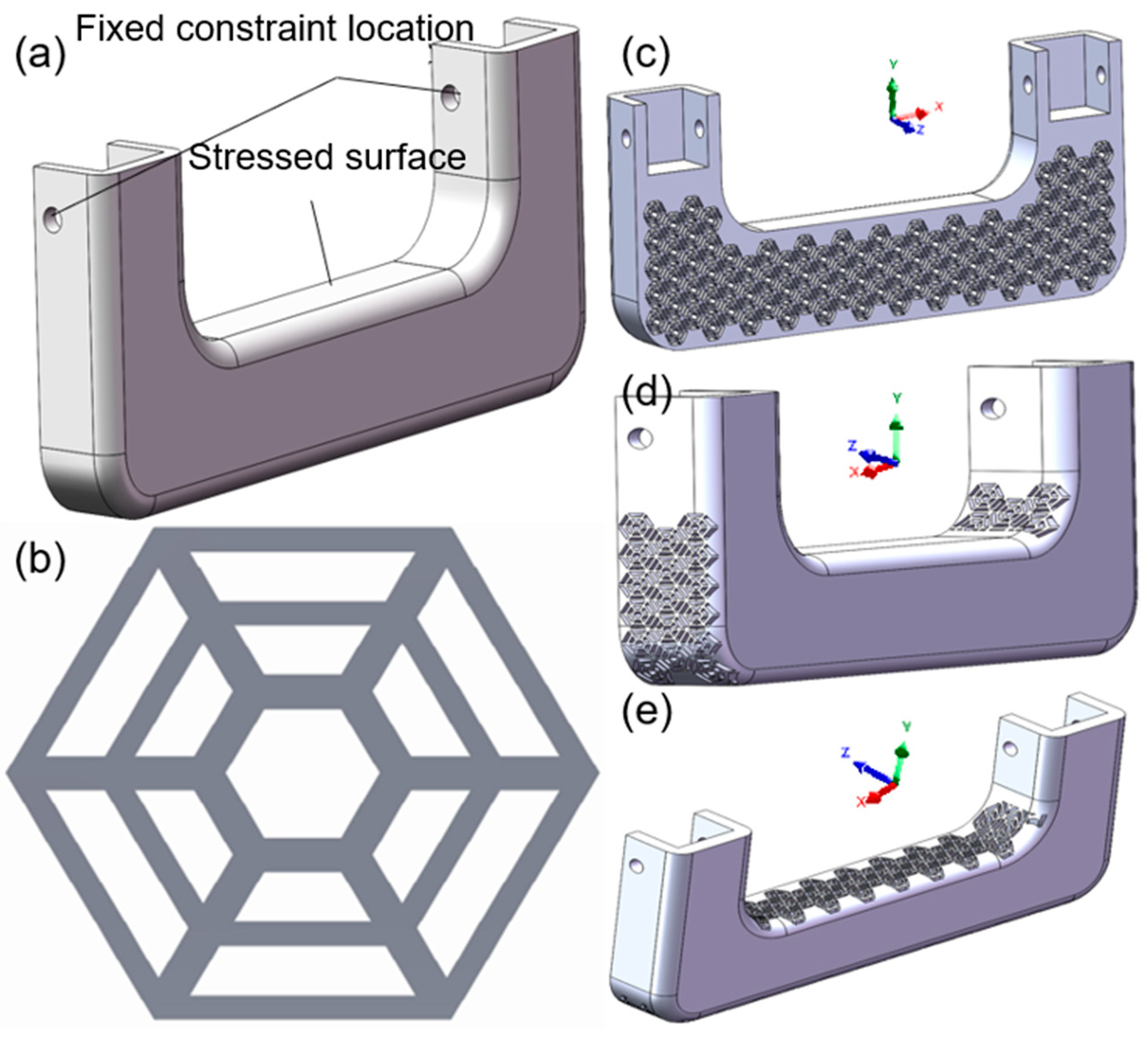
In order to further reduce the weight of the car, this work innovatively chose a spider web biomimetic structure for the lightweight design of the roof handrail, which combines performance and aesthetics. Firstly, based on the biomimetic structure of the Eight Trigrams spider web, combined with the U-shaped handrail of a specific NIO model, a model was created. Then, finite element software ANSYS 2024 R2 was used for simulation analysis to assist in design optimization. This work analyzed the influence of biomimetic spider web structures with different distribution directions on the performance of handrails. By comparing the performance of handrails made of PA6-CF and PLA Basic materials, analyzing their lightweight degree and mechanical properties, the optimal handrail material and structure were selected. In addition, for the first time, additive manufacturing technology was used to apply PA6-CF material to the roof handrail, achieving improvements in the handrail’s tensile strength and lightweight performance, as well as saving mold costs.

2. Methods of Simulation and Testing

2.1. Simulation

The main modeling of the car roof handrail is based on a certain NIO model, with a length of 17 cm, a width of 2 cm, a height of 7 cm, and a volume of 133.78 cm3, as shown in Figure 1a. The 3D modeling software adopts SOLIDWORKS 2024.
This work simplifies the complex configuration of the hexagram-shaped spider web into a simple geometric structure containing core structures such as capture filaments and radial filaments, as shown in Figure 1b, which is a biomimetic structure diagram of the hexagram shaped spider web.
Three simulation spider web structures were designed for the distribution of roof handrails. For the convenience of differentiation, each scheme is named based on the cutting direction of the hollow part of the spider web during the modeling phase, as illustrated in Figure 1c–e, and Table 1 summarizes the theoretical volumes modeled.
The car roof handrail needs to withstand significant tensile forces as it may face certain impacts; therefore, it needs to have good strength and sufficient elastic deformation ability. This work compares two materials, PA6-CF and PLA Basic. In addition to PA6-CF, PLA Basic is also one of the main materials for additive manufacturing of automotive interiors, with the advantages of being cheap and easy to process. This work uses simulation to study whether they have advantages in this design. These two materials are both products of Shenzhen Bambu Lab, (Shenzhen, China) and their main mechanical properties are shown in Table 2. These parameters are used for the static simulation material parameter settings of ANSYS 2024 R2.
For the range data, in order to design redundancy and safety considerations, the lower limit value is taken, and the final equivalent stress is the fiber direction stress.

2.2. Testing

This work uses additive manufacturing technology to manufacture experimental samples, with a single-layer thickness of approximately 0.127 mm [27]. The data of the car roof handrail model are imported into the software, and the processing parameters are shown in Table 3. The equipment used in this work is the Bambu Lab x1cc 3D modeling printer, which adopts the principle of Fused Deposition Modeling. This is a product of Shenzhen Bambu Lab, with a standard line width of 0.4 mm.
Complete sample processing for subsequent weighing and tensile testing. The test sample is shown in Figure 2.
Designed fixtures that mimic the fixing method of handrails in cars and the force application form of human hands are shown in Figure 3a,c. The machinery used in the experiment is a microcomputer controlled electronic universal testing machine produced by Jinan Lian Tai Test Equipment Co., Ltd. (Taizhou, China), model WDW-100Y.
Due to the much higher stiffness and hardness of the materials used for the fixture and fixing pin compared to PA6-CF and PLA Basic materials, as well as the deformation of the handrail including elongation caused by axial tensile deformation on both sides of the U-shaped handrail and deflection caused by bending deformation of the middle crossbeam, we can ignore the fixture deformation and process errors during the fixture manufacturing process. The external load is gradually increased from 0 N to 1500 N. The fixture design is shown in Figure 3b. Through experimental data, we can obtain the variation of clamp spacing of various handrails under unidirectional force, which can indirectly reflect the deformation of handrails and identify the stress and deformation stages of materials from the data curve, verify simulated data, and ensure the feasibility and reliability of actual products.

3. Simulation Result

3.1. Analysis of Biomimetic Handrails with Spider Webs of Different Structures

All simulations in this work were conducted in ANSYS 2024 R2. To understand the mechanical properties and structural characteristics of traditional handrails, static simulations were conducted on PA6-CF material for traditional car roof handrails under tensile loads of 500 N, 1000 N, and 1500 N. The result is shown in Figure 4.
From Table 4, it can be seen that the maximum equivalent stress and maximum total deformation generated by traditional handrails under different loads are within the allowable range of material strength for PA6-CF. On the other hand, the greater the elastic deformation while ensuring strength, the better the impact resistance experience provided by the handrail. The hexagram-shaped spider web biomimetic structure not only meets the requirements of lightweight and strength but also has excellent mechanical properties that can support greater elastic deformation requirements, improving the user experience of handrails [28]. In addition, spider web structures generally have good defect tolerance [29], allowing for significant simplification of the complexity of spider web structures while maintaining their original characteristics.
The spider web biomimetic structure handrail designed along the x-axis, when subjected to tensile forces of 500 N, 1000 N, and 1500 N, has a total deformation diagram and equivalent stress diagram as shown in Figure 5. The total deformation diagram and equivalent stress diagram of the scheme designed along the y-axis and z-axis are shown in Figure 6 and Figure 7.
By organizing the simulation data of a 500 N load and creating Table 5, it can be found that under low load conditions, the maximum equivalent stress of the spider web structure handrail designed along the z-axis is the smallest among the three designs. According to structural mechanics, the smaller the peak equivalent stress under load, the more stable and safer the structure. Therefore, the spider web biomimetic structure car roof handrail designed in the z-axis direction is more stable and safer compared to the handrails in the x-axis and y-axis directions. Comparing the handrail designed in the z-axis direction with the traditional roof handrail, its equivalent effectiveness and total deformation are greater than those of the traditional handrail, but within the allowable strength range of PA6-CF. This indicates that, while ensuring safety, the new structure can not only achieve light weight, but also improve the elastic deformation ability of the handrail to a certain extent, providing better cushioning.
The load is increased to 1000 N and 1500 N, and the obtained data are compiled into Table 6 for analysis.
The PA6-CF used in this study is a product from Shenzhen Bambu Lab, with a carbon fiber content exceeding 25%. It belongs to carbon fiber reinforced composite materials and is a brittle material [30]. Its characteristics conform to the first strength theory, which states that when the equivalent stress at a certain point exceeds the tensile strength limit of the material, the material will fracture. According to Table 6 analysis, under a load of 1000 N, the maximum equivalent stress of the spider web structure handrail designed along the x-axis reached 273.31 MPa, exceeding the tensile strength of PA6-CF in Table 2, indicating failure. Therefore, this scheme cannot meet the safety requirements under high loads.
When the load of the biomimetic structure handrail designed along the y-axis reaches 1500 N, the maximum equivalent stress reaches 233.13 MPa. According to Table 2, the tensile strength range of PA6-CF is 210~240 MPa. This work adopts the minimum value. According to the first strength theory, this scheme will fail under a load of 1500 N.
The safety factor is an indicator used to measure the structural safety of components, and its value is equal to the quotient of ultimate stress and maximum equivalent stress at work. When this value is greater than one, it indicates structural safety.
S = σ b σ
Due to the fact that the roof handrail is mainly subjected to tensile force, its strength limit is the tensile strength limit σb. The safety factor is S, and the maximum equivalent stress at work is σ. According to Table 2, the tensile strength of PA6-CF is between 210 and 240 MPa. Therefore, to be conservative, the ultimate stress is taken as 210 MPa. According to Table 6, when the load is 1500 N, the maximum equivalent stress at work is 189.11 MPa. So, the safety factor of the handrail design along the z-axis is 1.11, which is greater than 1.
Therefore, designing a spider web biomimetic structure handrail in the z-axis direction can meet safety requirements while achieving the lightweight goal of reducing weight by approximately 32.03%. Compared with traditional handrails, it can also increase the elastic deformation ability of handrails to a certain extent, optimizing the requirements of user experience.

3.2. Analysis of Biomimetic Handrails with Spider Webs of Different Materials

According to the finite element analysis of the PA6-CF material mentioned above, it can be concluded that the structure of the spider web biomimetic handrail designed along the z-axis direction is the best among the three new structural designs. Therefore, in the finite element analysis of different materials, the PLA Basic material designed spider web biomimetic structure handrail along the z-axis direction is directly selected for finite element simulation analysis.
The total deformation diagram and equivalent stress diagram of traditional handrails made of PLA Basic material subjected to tensile forces of 500 N, 1000 N, and 1500 N are shown in Figure 8.
The total deformation diagram and equivalent stress diagram of the spider web biomimetic structure handrail made of PLA Basic material under tension of 500 N, 1000 N, and 1500 N are shown in Figure 9.
By analyzing the simulation results, under the same load, the maximum equivalent stress of PLA Basic material handrail is lower than that of PA6-CF material handrail. However, the strength limits of the two materials are different. According to Formula 1, the safety factors of spider web biomimetic structure handrails made of two materials are calculated under extreme working conditions of 1500 N load. According to Table 2, the tensile strength of PA6-CF is 210 MPa, and the tensile strength of PLA Basic is 50 MPa. According to Table 7, the maximum equivalent stress at work for both at 1500 N are 189.11 MPa and 38.458 MPa, respectively. So, the safety factor index of PA6-CF handrail is 1.11, and the safety factor index of PLA Basic handrail is 1.3, both of which are greater than 1.
Therefore, both types of spider web handrails meet structural safety requirements. However, due to the higher tensile strength limit of PA6-CF material and the spider web structure handrail made from it allowing for greater elastic deformation, the handrail is more comfortable in daily low load repeated use, meeting the design expectations of optimizing the handrail user experience.

4. Test Results

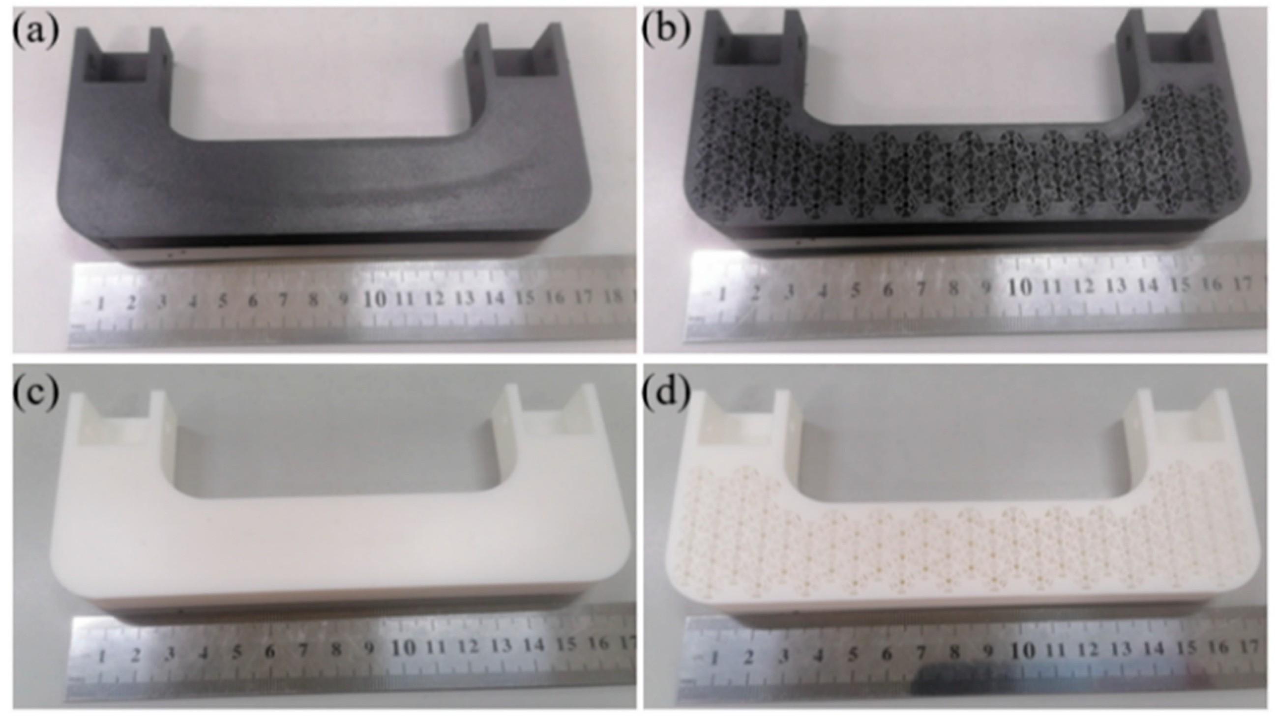
In the simulation, it was measured that the z-axis direction spider web biomimetic structure handrail had a theoretical weight reduction of about 32.03% compared to the traditional car roof handrail. The processed sample handrail was weighed and verified, and the results are shown in Table 8. The weighing equipment is an electronic balance.
According to Table 8, the weight reduction rate between the new and old structures of PA6-CF material is about 26.19%, while the weight reduction rate between the new and old structures of PLA Basic material is about 28.16%. During the production process of FDM-based printers using PA6-CF material, due to its large thermal deformation, the printing accuracy is reduced, and the process requires extending the single-layer printing time and improving heat dissipation, which to some extent affects the weight of the finished product and thus affects the weight reduction rate. However, the simulation results of the spider web structure handrail of PA6-CF show sufficiently excellent performance, so the results are further confirmed through tensile testing below.
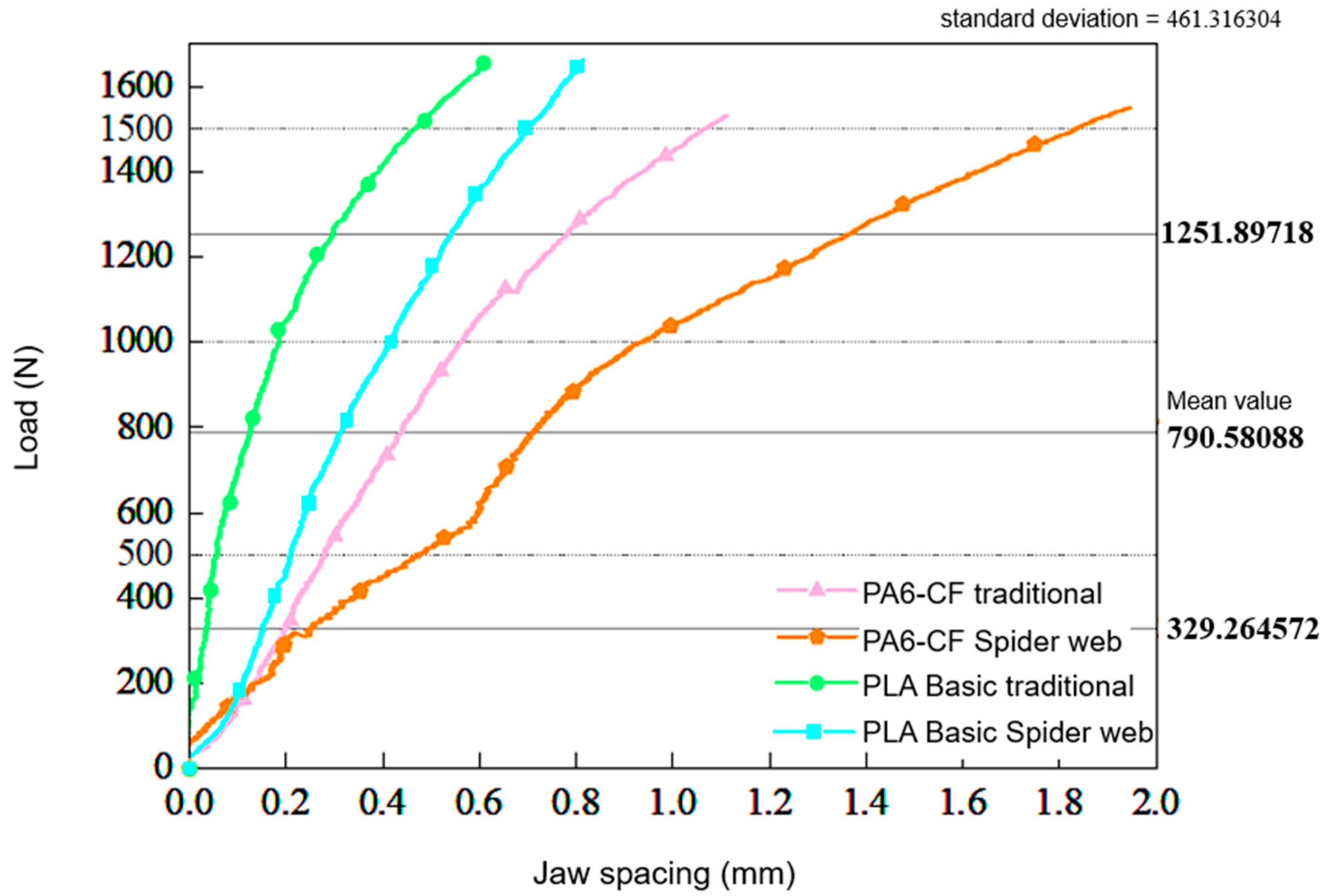
The load and deformation data graph of the test results is shown below.
According to Figure 10, the handrails of both materials are in the elastic deformation range. Since both materials are brittle, if failure occurs, the curve should show a sudden drop in fluctuation. The curve in the figure indicates that all tested handrails can withstand a static load of 1500 N. At present, the standards for roof handrails used by various car brands are not uniform. Some brands only require a load-bearing capacity of 50–80 kg, while others require a load-bearing capacity greater than 150 kg. Therefore, the test results using 1500 N as the highest load standard in this work can demonstrate that the spider web structure handrail in this design meets the usage requirements.
Comparing the experimental results of different configurations of handrails under the same material, it can be seen that compared with traditional handrail structures, using spider web biomimetic structures increases elastic deformation and improves the energy dissipation capacity of the product [31], which is in line with the laws in the simulation process. This feature is beneficial for improving the cushioning performance of the handrail during use and optimizing the user experience of the handrail.
Comparing handrails made of different materials, it was found that the degree of elastic deformation of PA6-CF material handrails is greater than that of PLA Basic material handrails. Both materials are brittle, and there is no sudden sharp drop in the curve from Figure 10, so no brittle fracture has occurred, so they are still in the stage of elastic deformation. From Table 2, it can be seen that the PA6-CF material selected in this work has a smaller Young’s modulus compared to the PLA base material, so PA6-CF usually has greater elastic deformation under the same load [32,33]. Therefore, the PA6-CF material handrail not only meets the usage requirements, but also provides better grip stability due to its high elastic deformation ability, can absorb some impact energy, reduce the impact on the arm during sudden bumps, and thus provide a better user experience. From the perspective of comprehensive safety and comfort, the PA6-CF material is more suitable.
In summary, the spider web biomimetic structure handrail of PA6-CF can ensure the strength of the handrail itself, further reduce the weight of automotive handrail components, optimize the handrail user experience, and meet the safety requirements of automotive use [34].

5. Conclusions

This work combines additive manufacturing, simulation, automotive lightweight design, biomimetic structure, and other technologies, starting from the relatively inconspicuous roof handrail in automobiles, attempting to break down the huge engineering of automotive lightweighting into a series of small parts for lightweight design. The following summary is drawn from the simulation and experiment of the spider web biomimetic structure handrail:
1. This work integrates the spider web biomimetic structure into the roof handrail through additive manufacturing technology, achieving lightweight design of the roof handrail. Compared with traditional handrails, the theoretical weight of the spider web biomimetic structure handrail is reduced by 32.03%, and the actual weight is reduced by about 26.19%.
2. This work compares and analyzes three distribution combinations of spider web biomimetic structures on handrails, and clarifies that the spider web biomimetic handrail structure designed along the z-axis is the best solution.
3. This work pioneers the application of PA6-CF material in the manufacturing of roof handrails, improving their performance.
4. This work compares the handrail performance of PA6-CF and PLA Basic materials through finite element simulation analysis and experiments and determines the advantages of PA6-CF material in spider web biomimetic structure handrails. The handrail made of PA6-CF material not only meets the performance requirements but also ensures a good user experience.

6. Future Prospects

6.1. Lightweight Structure Optimization and Promotion

The application of the spider web biomimetic structure on the roof handrail can serve as a case study, gradually applying this structure to similar components in or outside of automobiles to achieve lightweight and even performance optimization. As a system, the lightweighting engineering of automobiles should be a qualitative change caused by the gradual lightweighting of various components.

6.2. Promotion of Additive Manufacturing Technology

Additive manufacturing technology, as a gradually industrialized and commercialized new processing technology, should be attempted to be applied to more parts production. Additive manufacturing technology is more flexible than traditional assembly line production processes for small and medium-sized orders and personalized customization orders. With the emergence of industrial grade 3D printers, the production capacity is sufficient to meet market demand. Moreover, there are still many parts in the automotive industry that are similar to roof rails and can be produced using additive manufacturing technology to save mold and process costs, improve product performance, and enhance market competitiveness.

Author Contributions

Q.C. Conceptualization, Methodology. H.W. Writing—Review and Editing, Validation. Z.L. Investigation, Data Curation. Y.H. Software, Writing—Original draft. S.Y. Conceptualization, Methodology. All authors have read and agreed to the published version of the manuscript.

Funding

This research did not receive any specific grant from funding agencies in the public, commercial, or not-for-profit sectors.

Data Availability Statement

The data analyzed in this study are available from the corresponding author on reasonable request.

Conflicts of Interest

The authors declare that they have no known competitors, and any potential social interests or personal relationships may affect the work reported in this work.

References

  1. Xu, S.; Ji, Z.; Xiao, P. Status and prospect of automobile lightweight technology. J. Automot. Saf. Energy 2025, 16, 16–31. [Google Scholar]
  2. Guo, H. Application Analysis of 3D Printing Technology in Body Shop. Automob. Appl. Technol. 2024, 49, 133–136. [Google Scholar] [CrossRef]
  3. Lv, W.; Mao, P.; Cobby, J. Dynamic Characteristics Analysis of Small Electric Vehicle Wheel Hubs. Mod. Manuf. Eng. 2020, 20, 57–61. [Google Scholar] [CrossRef]
  4. Jung, S.; Kara, L.B.; Nie, Z.; Simpson, T.W.; Whitefoot, K.S. Is Additive Manufacturing an Environmentally and Economically Preferred Alternative for Mass Production? Environ. Sci. Technol. 2023, 57, 6373–6386. [Google Scholar] [CrossRef]
  5. Li, H.; Kong, M.; Wang, S.; Wang, Y. Application and Effect Analysis of Additive Manufacturing in Mass Production of Automotive Interior Parts. Auto Know 2024, 24, 58–60. [Google Scholar]
  6. Li, X.; Zhang, S.; Jiang, P.; Nie, M.; Kong, D.; Kang, Z.; Liu, M.; Zhu, D.; Jiang, C.; Zhang, Q.; et al. Smart Bionic Structures: Connecting Nature and Technology through Additive Manufacturing. Addit. Manuf. Front. 2024, 3, 200137. [Google Scholar] [CrossRef]
  7. Yang, H.; Yin, X.; Wang, S.; Yu, M. Application of AlSi10MnMg Materials in Lightweight Automotive Body. Automob. Technol. 2024, 49, 167–171. [Google Scholar] [CrossRef]
  8. Li, M.; Liang, G.; Wang, C.; Chen, H. Bamboo fiber automotive interior sandwich structure lightweight composite material performance. World Bamboo Ratt. 2024, 22, 12–21. [Google Scholar]
  9. Qiao, J.; Wang, C.; Chen, X. Structural optimization and axial low-velocity impact performance of 3D printed auxetic columnar honeycomb structure. Mater. Eng. 2025, 68, 1–12. Available online: http://kns.cnki.net/kcms/detail/11.1800.TB.20250612.1416.035.html (accessed on 22 June 2025).
  10. Huang, Y.; Zhuo, Y.; Wang, X. Quantitative analysis of spider web structure. J. Southwest Norm. Univ. (Nat. Sci. Ed.) 2013, 38, 44–48. [Google Scholar]
  11. Zhao, Y.; Wu, J.; Zhang, R. Exploration of the optimal web building model for spider webs. Sci. Technol. Assoc. Forum 2013, 3, 86–88. [Google Scholar]
  12. Guo, X. Design and Fabrication and Verification of Spider Web-like SiCf/SiC Monolithic Turbine Disk. Ph.D. Thesis, Central South University, Changsha, China, 2023. [Google Scholar] [CrossRef]
  13. Zhang, L.; Han, Z.; Zang, Y.; Han, Z.; Wang, X. Design and 3D finite element analysis of personalized titanium mesh with biomimetic spider web pore structure 3D printing. Chin. J. Tissue Eng. Res. 2023, 27, 4796–4801. [Google Scholar]
  14. Kartanas, L.; Bhavan, J.S. Design, Development, and Performance Evaluation of a Lightweight Short Shifter for Enhanced Gear-Shifting Quality in Automobile. J. Inst. Eng. India Ser. D 2023, 105, 863–873. [Google Scholar] [CrossRef]
  15. Plocher, J.; Panesar, A. Review on design and structural optimisation in additive manufacturing: Towards next-generation lightweight structures. Mater. Des. 2019, 183, 108164. [Google Scholar] [CrossRef]
  16. Kutnjak-Mravlinčić, S.; Godec, D.; Pilipović, A.; Sutlović, A. Optimization of the FDM Processing Parameters on the Compressive Properties of ABS Objects for the Production of High-Heeled Shoes. J. Manuf. Mater. Process. 2024, 8, 106. [Google Scholar] [CrossRef]
  17. Friedrich, C.; Rothstock, S.; Slabon, L.; Ihlenfeldt, S. Additive In-Time Manufacturing of Customised Orthoses. J. Manuf. Mater. Process. 2024, 8, 63. [Google Scholar] [CrossRef]
  18. Xia, M. General Electric receives airworthiness certification for its first 3D printed engine component. Ordnance Mater. Sci. Eng. 2021, 44, 32. [Google Scholar] [CrossRef]
  19. Hoffmann, K.G.; Haag, K.; Müssig, J. Biomimetic approaches towards lightweight composite structures for car interior parts. Mater. Des. 2021, 212, 110281. [Google Scholar] [CrossRef]
  20. Almonti, D.; Salvi, D.; Ucciardello, N. Optimization of printing parameters for polyethylene terephthalate glycol thin honeycomb structures with shape-memory behaviors. Int. J. Adv. Manuf. Technol. 2025, 136, 4455–4469. [Google Scholar] [CrossRef]
  21. He, X.; Wang, W.; Liu, Y.; Jiang, M.; Wu, F.; Deng, K.; Liu, Z.; Ju, X.; Xie, R.; Chu, L. Microfluidic Fabrication of Bio-Inspired Microfibers with Controllable Magnetic Spindle-Knots for 3D Assembly and Water Collection. ACS Appl. Mater. Interfaces 2015, 7, 17471–17481. [Google Scholar] [CrossRef]
  22. Saito, G. The Development and Prospect of Spatial Structure; China Architecture & Building Press: Beijing, China, 2006. [Google Scholar]
  23. Ko, K.F.; Jovicic, J. Modeling of mechanical properties and structural design of spider web. Biomacromolecules 2004, 5, 780–785. [Google Scholar] [CrossRef]
  24. Sensing, A.T.; Lorentz, K.A.; Kelly, S.P.; Blackledge, T.A. Spider orb webs rely on radial threads to absorb prey kinetic energy. J. R. Soc. Interface 2012, 9, 1880–1891. [Google Scholar] [CrossRef] [PubMed]
  25. Chen, W.; Hu, Z.; Li, X.; He, J.; Wang, S.; Zhao, Y.; Li, M.; Zhang, J. Additive manufacturing of high-strength polyamide 6 composites reinforced with continuous carbon fiber prepreg. Polym. Compos. 2024, 45, 668–679. [Google Scholar] [CrossRef]
  26. Zhou, W.; Li, X. Additive Manufacturing and Application of Polylactic Acid Materials. Micronanoelectron. Technol. 2024, 61, 36–53. [Google Scholar] [CrossRef]
  27. Guduru, K.K.; Gangisetti, S. Mechanical Characterization of 3D Printed Carbon Fiber Reinforced PLA Composite and Parameters Optimization. Adv. Sci. Technol. 2024, 157, 27–33. [Google Scholar]
  28. Luo, C.; Li, F.; Li, D.; Fu, Q.; Pan, C. Bioinspired Single-Walled Carbon Nanotubes as a Spider Silk Structure for Ultrahigh Mechanical Property. ACS Appl. Mater. Interfaces 2016, 8, 31256–31263. [Google Scholar] [CrossRef]
  29. Cranford, S.W.; Tarakanova, A.; Pugno, N.M.; Buehler, M.J. Nonlinear material behaviour of spider silk yields robust webs. Nature 2012, 482, 72–76. [Google Scholar] [CrossRef]
  30. Tian, Y.; Hu, L. Preparation and Mechanical Properties of Polyamide 6/Short Carbon Fiber Composites. Eng. Plast. Appl. 2022, 50, 30–35. [Google Scholar]
  31. Mohammadi, H.; Ahmad, Z.; Petrů, M.; Mazlan, S.A.; Johari, M.A.F.; Hatami, H.; Koloor, S.S.R. An insight from nature: Honeycomb pattern in advanced structural design for impact energy absorption. J. Mater. Res. Technol. 2023, 22, 2862–2887. [Google Scholar] [CrossRef]
  32. Dogru, A.; Seydibeyoglu, M.O. The effect of printing parameters on the mechanical properties of fiber-reinforced PA6 matrix composites in material extrusion-based additive manufacturing. Rapid Prototyp. J. 2024, 30, 1287–1300. [Google Scholar] [CrossRef]
  33. Li, M.; Xu, Y.; Fang, J. Orthotropic mechanical properties of PLA materials fabricated by fused deposition modeling. Thin-Walled Struct. 2024, 199, 111800. [Google Scholar] [CrossRef]
  34. Xie, G.; Li, Z.; Yuan, N.; Li, R.; Li, K. Toward Effective Reliability Requirement Assurance for Automotive Functional Safety. ACM Trans. Des. Autom. Electron. Syst. 2018, 23, 1–26. [Google Scholar] [CrossRef]
Figure 1. (a) Traditional car roof handrail diagram, (b) spider web structure diagram, (c) spider web biomimetic structure handrail in the z-axis direction, (d) spider web biomimetic structure handrail in the x-axis direction, (e) spider web biomimetic structure handrail in the y-axis direction.
Jmmp 09 00228 g001
Figure 2. (a) PA6 traditional handrail, (b) PA6 spider web handrail, (c) PLA traditional handrail, (d) PLA spider web handrail.
Jmmp 09 00228 g002
Figure 3. (a) Fixture schematic diagram, (b) fixture assembly diagram, (c) experimental diagram.
Jmmp 09 00228 g003
Figure 4. Total deformation diagram and equivalent stress diagram of the traditional car roof handrail, (a,b) a tensile load of 500 N, (c,d) a tensile load of 1000 N, (e,f) a tensile load of 1500 N.
Jmmp 09 00228 g004
Figure 5. Total deformation diagram and equivalent stress diagram of the spider web structure handrail in the x-axis direction, (a,b) a tensile load of 500 N, (c,d) a tensile load of 1000 N, (e,f) a tensile load of 1500 N.
Jmmp 09 00228 g005
Figure 6. Total deformation and equivalent stress diagram of the spider web structure handrail in the y-axis direction, (a,b) a tensile load of 500 N, (c,d) a tensile load of 1000 N, (e,f) a tensile load of 1500 N.
Jmmp 09 00228 g006
Figure 7. Total deformation diagram and equivalent stress diagram of the spider web structure handrail in the z-axis direction, (a,b) a tensile load of 500 N, (c,d) a tensile load of 1000 N, (e,f) a tensile load of 1500 N.
Jmmp 09 00228 g007
Figure 8. Total deformation diagram and equivalent stress diagram of PLA traditional handrail, (a,b) a tensile load of 500 N, (c,d) a tensile load of 1000 N, (e,f) a tensile load of 1500 N.
Jmmp 09 00228 g008
Figure 9. Total deformation diagram and equivalent stress diagram of PLA spider web structure handrail, (a,b) a tensile load of 500 N, (c,d) a tensile load of 1000 N, (e,f) a tensile load of 1500 N.
Jmmp 09 00228 g009
Figure 10. Results of external load and deformation of traditional and spider web handrails with different materials in tensile tests.
Jmmp 09 00228 g010
Table 1. Volume of handrails in three design directions compared to traditional handrails.
Structural Distribution DirectionVolume (cm3)
X-axis direction89.72
Y-axis direction94
Z-axis direction90.92
Traditional handrails133.78
Table 2. Main mechanical properties of PLA Basic [25,26].
DataPLA BasicPA6-CF
Density (g/cm3)1.24–1.261.17
Tensile strength (MPa)50–65210–240
Young’s modulus (GPa)3.2–3.818–22
Poisson’s ratio0.350.30
Flexural strength (MPa)80–95280–320
Flexural modulus (GPa)3.5–4.220–25
Table 3. Specific data of printing parameters for PA6 and PLA materials.
PLA BasicPA6-CF
Printing layer height (mm)0.20.2
First layer velocity (m/s)5050
Other layer velocities (m/s)7070
Printing temperature (°C)220260
Hot bed temperature (°C)50100
Printing material diameter (mm)1.751.75
Number of external walls (layers)66
Table 4. Static simulation results of traditional handrails.
Load (N)Maximum Equivalent Stress (MPa)Maximum Total Deformation (mm)
50050.540.27977
1000100.840.55769
1500151.140.83561
Table 5. Maximum equivalent stress and maximum total deformation of handrails in three design directions and traditional handrails under a load of 500 N.
TypesMaximum Equivalent Stress (MPa)Maximum Total Deformation (mm)
X-axis136.741.0096
Y-axis77.7960.60627
Z-axis63.1480.47
Traditional50.540.27977
Table 6. Maximum equivalent stress and maximum total deformation of handrails under 1000 N and 1500 N loads.
Load (N)TypesMaximum Equivalent Stress (MPa)Maximum Total Deformation (mm)
1000X-axis273.312.0153
Y-axis155.461.2101
Z-axis126.130.93783
Traditional100.840.55769
1500X-axis409.873.0209
Y-axis233.131.814
Z-axis189.111.4057
Traditional151.140.83561
Table 7. Maximum equivalent stress and maximum total deformation of handrails under different loads for different materials.
TypesMaterialsLoad (N)Maximum Equivalent Stress (MPa)Maximum Total Deformation (mm)
TraditionalPA6-CF50050.540.27977
1000100.840.55769
1500151.140.83561
PLA Basic50014.4170.061788
100028.7970.18343
150043.1770.27508
Spider web structurePA6-CF50063.1480.47
1000126.130.93783
1500189.111.4057
PLA Basic50012.8340.20864
100025.6460.41713
150038.4580.62561
Table 8. Weight of traditional handrails and spider web structured handrails under different materials.
PA6 Traditional PA6 Spider Web PLA Traditional PLA Spider Web
Actual weight (g)140.96104.04168.42121.00
Simulated weight (g)156.52106.38165.89112.74
Disclaimer/Publisher’s Note: The statements, opinions and data contained in all publications are solely those of the individual author(s) and contributor(s) and not of MDPI and/or the editor(s). MDPI and/or the editor(s) disclaim responsibility for any injury to people or property resulting from any ideas, methods, instructions or products referred to in the content.

