Article

Effect of Pulsating Motion Conditions on Relubrication Behavior and Dimensions of Laterally Extruded Internal Gears

by
Alireza Soleymanipoor
1,* and
Tomoyoshi Maeno
2
1
Department of Mechanical Engineering, Materials Science, and Ocean Engineering, Graduate School of Engineering Science, Yokohama National University, Yokohama 240-8501, Kanagawa, Japan
2
Division of Systems Research, Faculty of Engineering, Yokohama National University, Yokohama 240-8501, Kanagawa, Japan
*
Author to whom correspondence should be addressed.
J. Manuf. Mater. Process. 2025, 9(6), 190; https://doi.org/10.3390/jmmp9060190
Submission received: 24 April 2025 / Revised: 1 June 2025 / Accepted: 5 June 2025 / Published: 10 June 2025

Abstract

An environmentally friendly alternative to phosphate-based lubrication was studied through the lateral cold extrusion forging of internal gears using pulsating motion. A die set with a removable punch enabled a detailed observation of relubrication, forming load, material flow, and gear geometry. Pulsating motion with liquid lubricant significantly reduced the forming load during punch penetration, while no such effect was observed under dry conditions. Even when the number of pulses (n) was set to 1, relubrication occurred, and a comparable load reduction to that of n = 3 was achieved, shortening the forming time. When n = 3, pulsating motion contributed to increased gear height and reduced separated burr formation; however, it also caused slightly incomplete tooth filling, which may be undesirable for precision applications. Varying the pulse start position from 5.50 mm to 13.30 mm influenced forming load and material flow, further affecting gear geometry. During punch extraction, the presence of liquid lubricant reduced the load and suppressed material displacement, while dry conditions led to higher extraction loads and more deformation.

1. Introduction

Cold forging and extrusion offer significant advantages over other manufacturing methods, including minimal material waste, high dimensional accuracy, reduced or eliminated need for machining, superior surface finish, and enhanced mechanical properties due to favorable grain flow in the material [1]. The fundamental types of cold extrusion processes are categorized based on the direction of material flow, as follows: forward, upward, and lateral (or radial) extrusion. In these processes, lateral extrusion is defined as a forming method in which one or two opposing punches move axially, causing radial material flow into a die cavity or an annular space. The initial billet can be either a solid cylinder or a tube [2].
Complex components such as collar flanges, spur gear profiles, and shaft-integrated splines are among the typical products manufactured through lateral extrusion. Spur gears and splines serve as essential machine elements designed to transmit loads and torque, often operating at high rotational speeds. As a result, there is significant industrial demand for producing these parts with high strength and narrow dimensional tolerances. It is known that gears formed through plastic deformation exhibit superior fatigue strength and longer service life compared to those machined from the same material. Moreover, forming processes offer notable material savings relative to machining. To lower production costs and enhance competitiveness in demanding markets, it is essential to form components as near-net or net shapes, thereby minimizing the need for subsequent operations like machining [3].
Can et al. [3] developed an analytical model to analyze the lateral extrusion of spline and spur gears. They estimated punch pressure and extrusion load under varying conditions and found that pressure increased with more teeth, higher friction, and thinner splines. Jafarzadeh et al. [4] studied the lateral extrusion of gear-like parts using finite element modeling and examined how billet size, gap height, and friction affect forming load, material flow, and strain. Their study provided insights for optimizing die design and process parameters. Altinbalik and Ayer [5] conducted a comparative study on forming spur gears using forward and lateral extrusion. Using AA1070 aluminum billets and five die designs, they found that lateral extrusion required about 72% less forming load than forward extrusion. Fatigue tests also showed a 25% improvement in strength for gears made by lateral extrusion, indicating it as a more efficient method with better mechanical performance.
Lubrication is essential in cold forging with significant surface enlargement and raised surface temperature to reduce friction and enable smooth sliding between the workpiece and die [6]. Otherwise, surface defects like galling or seizure can occur without proper lubrication, leading to product failure [7]. Although the conversion coating of zinc phosphate plus a metal soap-based lubrication system has been used for a long time to facilitate lubrication in cold forging, its negative environmental impact has led to more eco-friendly alternatives to meet ecological demands. Bay et al. [8] reviewed the environmentally benign lubricants for metal forming processes. Sagisaka et al. [9] developed the double-layer lubricant system, featuring an undercoat for strong adherence and an overcoat for reduced friction with pretreated wet blasting to improve the lubrication performance. Wang et al. [10] et al. investigated the performance of lubrication coatings developed for substituting phosphate conversion coating in multi-stage cold forging. Since the coated film peeled off during the first stage, it could not show good anti-galling ability in subsequent stages. However, wet blasting before coating enhanced the performance of the anti-galling ability. Oshita et al. [11] investigated the friction behaviors of solid lubricants on grooved surfaces. The textured surface improved the anti-seizure behavior of the contacted surfaces. Volts et al. [12] evaluated zinc phosphate-free lubricants through global round-robin tribometer tests, finding that high surface expansion ratios increase wear risk. Successful substitution requires considering the required factors in process design and lubricant selection.
Many preparation approaches have been applied to maintain lubrication performance during the forging operations; however, sufficient lubrication is not ensured during forging with significant surface enlargement, making the relubrication of the workpiece and tools effective. Mechanical servos press machines with flexible ram motions, such as pulsating or oscillating motions, developed in recent years, have proven useful in improving relubrication, controlling plastic flow and temperature, and enhancing the shape and dimensional accuracy of the final product [13]. In pulsating motion, the ram repeatedly moves forward (downward or advance), and backward (upward or retreat) during the forming process until bottom dead center. Maeno et al. [14] developed an automatic re-lubrication method using a load pulsation of a servo press to reduce force in plate forging. This technique automatically feeds lubricant into the small gap between the plate and die, created by elastic recovery during load release. Matsumoto et al. [15] prevented galling and seizure in backward extrusion by automatically supplying lubricant through a punch with a lubricant channel using the pulsating ram motion of a servo press.
In addition to the inherent relubrication feature of forging with servo press machines using pulsating ram motion, this forging proves beneficial for controlling plastic flow and temperature while improving the shape and dimensional accuracy of the final product. Ishikawa et al. [16] controlled thermal contraction in cold forging of aluminum alloys by applying pulsating motion, which promoted a more uniform temperature distribution during deformation and thus improved dimensional accuracy, as localized plastic heat generation cannot be mitigated effectively through post-deformation cooling alone. Matsumoto et al. [17] investigated the use of pulsating motion in extrusion to control temperature and reduce galling. Intermittent punch retreats allowed lubricant to reach critical areas and lowered peak temperatures caused by plastic deformation. This improved thermal control enhanced shape accuracy and minimized friction-related issues. Matsumoto et al. [18] applied a pulse punch motion forming method to high-aspect-ratio forward-upward extrusion, finding that periodic lubricant supply reduced shear friction but increased punch wear compared to conventional forming. Moreover, the maximum temperature dropped periodically during the punch retreat in each forming step, thereby preventing excessive temperature rise in the specimen. On the other hand, thermal stresses, which pose a risk of cracking due to high temperatures during the forging process without pulsating motion and affect final quality, can be suppressed by pulsating motion. This mechanism is similar to a study that employed various directed energy deposition (DED) strategies for printing IN738 samples via additive manufacturing of superalloys to control and reduce thermal stresses and suppress cracking, thereby ensuring the quality of the final product [19]. Maeno et al. [20] demonstrated the effectiveness of load pulsating using a servo press in the plate forging of stainless steel.
Groche and Heß [21] introduced a closed-loop control system to improve the geometry of semi-finished forged products by controlling the forming force and, consequently, the final dimensions using pulsating motion. Maeno et al. [22] developed a backward extrusion process for cups with internal splines using pulsating motion and examined its effect on seizure prevention. Moreover, Maeno et al. [23] applied Automatic re-lubrication using pulsating motion to improve the sheared edge quality in stainless steel plate punching. The punch corner was re-lubricated by negative pressure generated during the upstroke, reducing adhesion and preventing cracks. Kuo et al. [24] optimized the pulsating curve for the servo stamping of the rectangular cup, which led to improved formability, increased forming depth, and reduced thinning and forming force. Meng et al. [25] developed a vibration-assisted clutch-forming method, and its effects on forming load reduction and surface quality were studied experimentally. Müller et al. [26] examined superimposed oscillation in gear ironing, finding it improves mold filling and surface quality, especially in dry conditions, while high amplitudes enhance effects with lubrication. Ben et al. [27] evaluated friction behavior in an oscillation-assisted T-shape forming process with continuous re-lubrication, showing that the nonlinear elastic response in loading-unloading cycles led to a decrease in the friction factor. Groche et al. [28] predicted the effects of oscillation on wear in the cold forging process. Oscillation influences friction and tool wear; however, conventional wear prediction models fail due to neglecting local lubrication conditions. Matsumoto et al. [29] found that pulsed ram motion in hot forging re-lubricates the workpiece, reducing forging load and increasing extruded length. Zhang et al. [30] investigated oscillating cold forging and conventional cold forging for spline shafts, finding that oscillating cold forging reduces forming force while also producing smoother spline surfaces compared to conventional cold forging. Matsumoto et al. [31] observed the contact interface in forging with ram pulsation, finding that complete unloading ram pulsation enabled re-lubrication, reducing forming load and forming lubricant pockets on the workpiece.
In the cold forging of bottomed internal gear products, such as transmission drum gears, an initial cup-shaped billet is used to form a bottomed internal gear. During this process, a designed punch penetrates the billet, causing deformation. However, the extraction of the punch from the deformed billet is inevitable and may impact the dimensional accuracy of the final product. Therefore, analyzing material flow both before and after punch extraction is essential.
In this study, the lateral cold extrusion forging of an internal gear from a ring-shaped billet using pulsating motion was investigated. A key novelty of this work is the use of a punch with a removable mechanism, which enabled the observation of material flow before and after punch extraction, allowing a detailed analysis of extraction effects. Additionally, various pulsating motion parameters were applied to examine their influence on relubrication, forming load, and the final gear geometry. This approach made it possible to generate internal gears with distinct shapes, demonstrating the significance of punch motion design in achieving desired forming outcomes.

2. Investigation of Relubrication Efficiency and Dimensional Changes in Laterally Extruded Internal Gears Under Pulsating Motion Conditions

Eliminating conversion phosphate coating in metal-forming processes is necessary for ecological compliance. However, applying the substitute lubricant is challenging when the lubricant film breaks due to surface enlargement, resulting in surface defects caused by an insufficient lubricant supply during the process. The use of pulsating motion has proven effective in facilitating relubrication during forming processes, while controlling the forming force and the shape of the produced products. Since the pulsating motion parameters affect the relubrication phenomena, an experimental setup was designed to investigate the subsequent forming force and shape of the laterally extruded internal gear, considering the effect of pulsating motion process parameters on the shape of the laterally extruded internal gear.

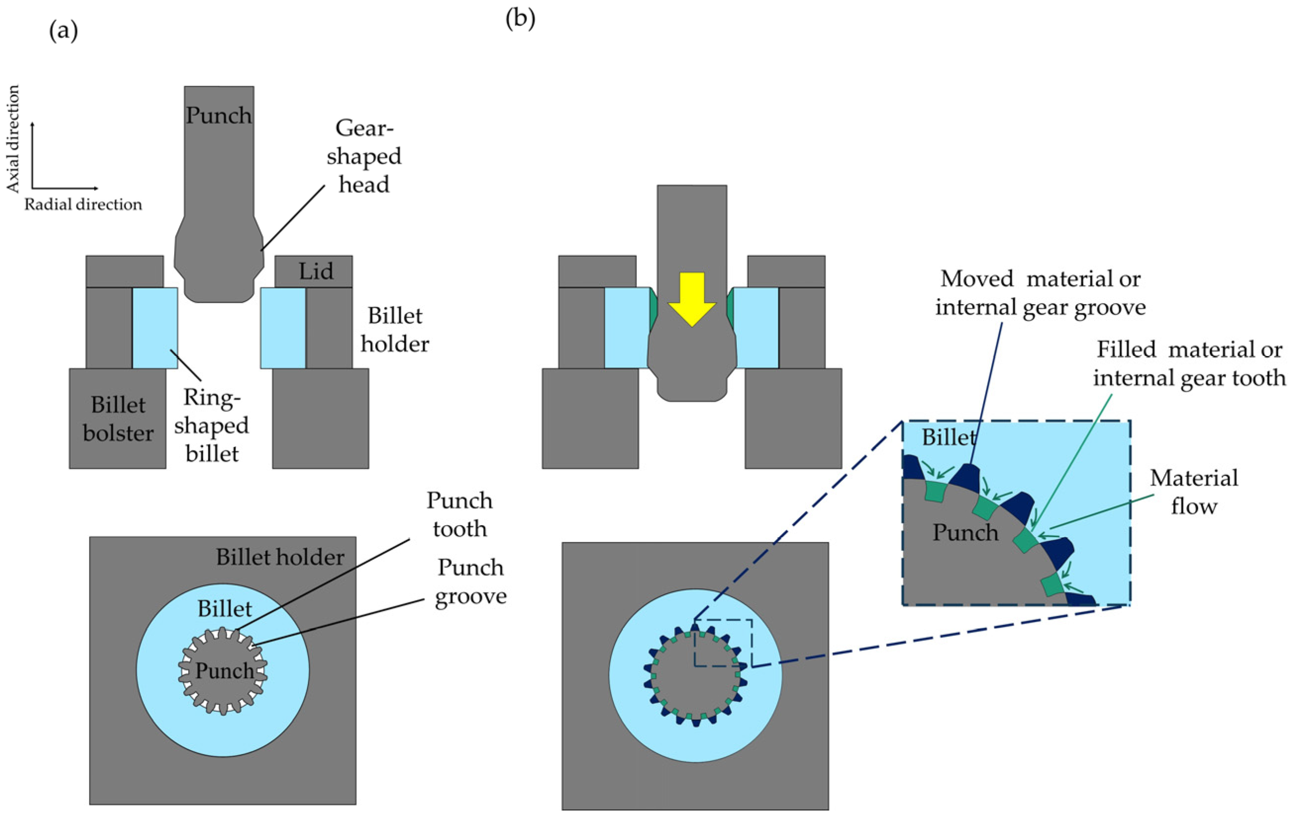
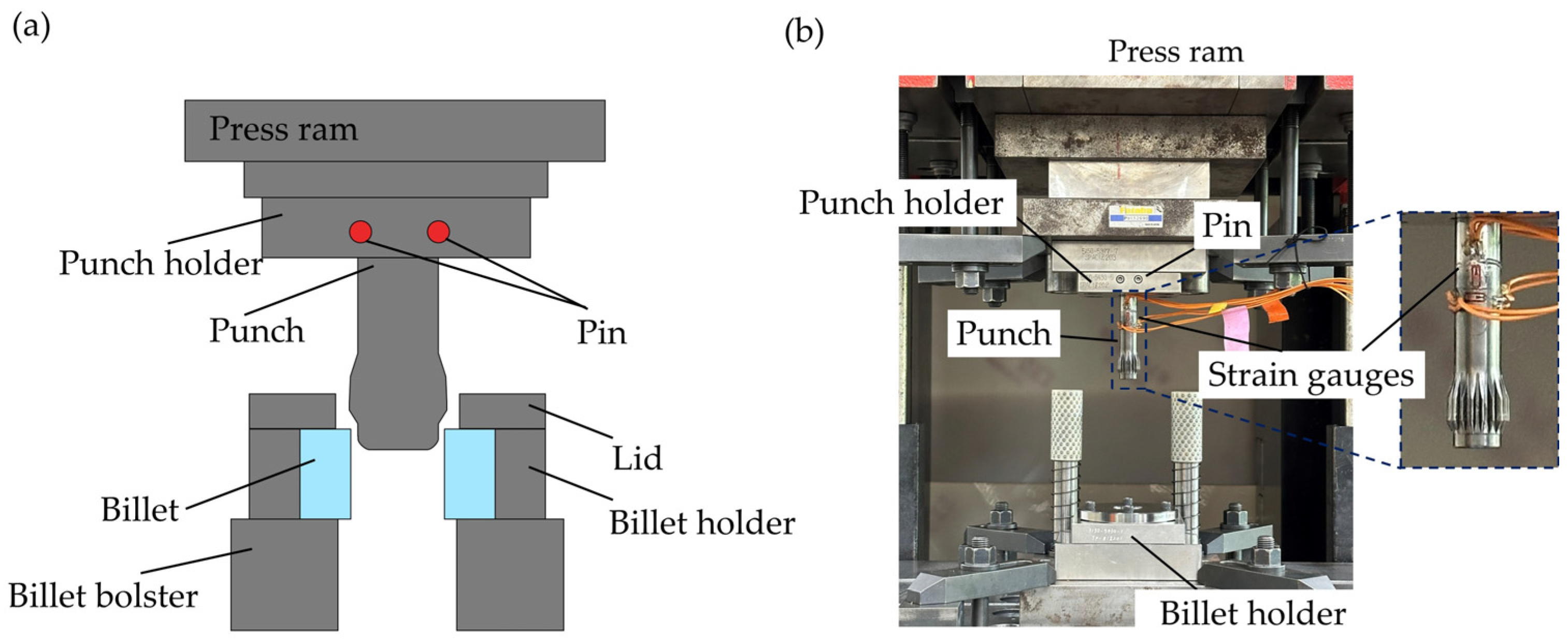
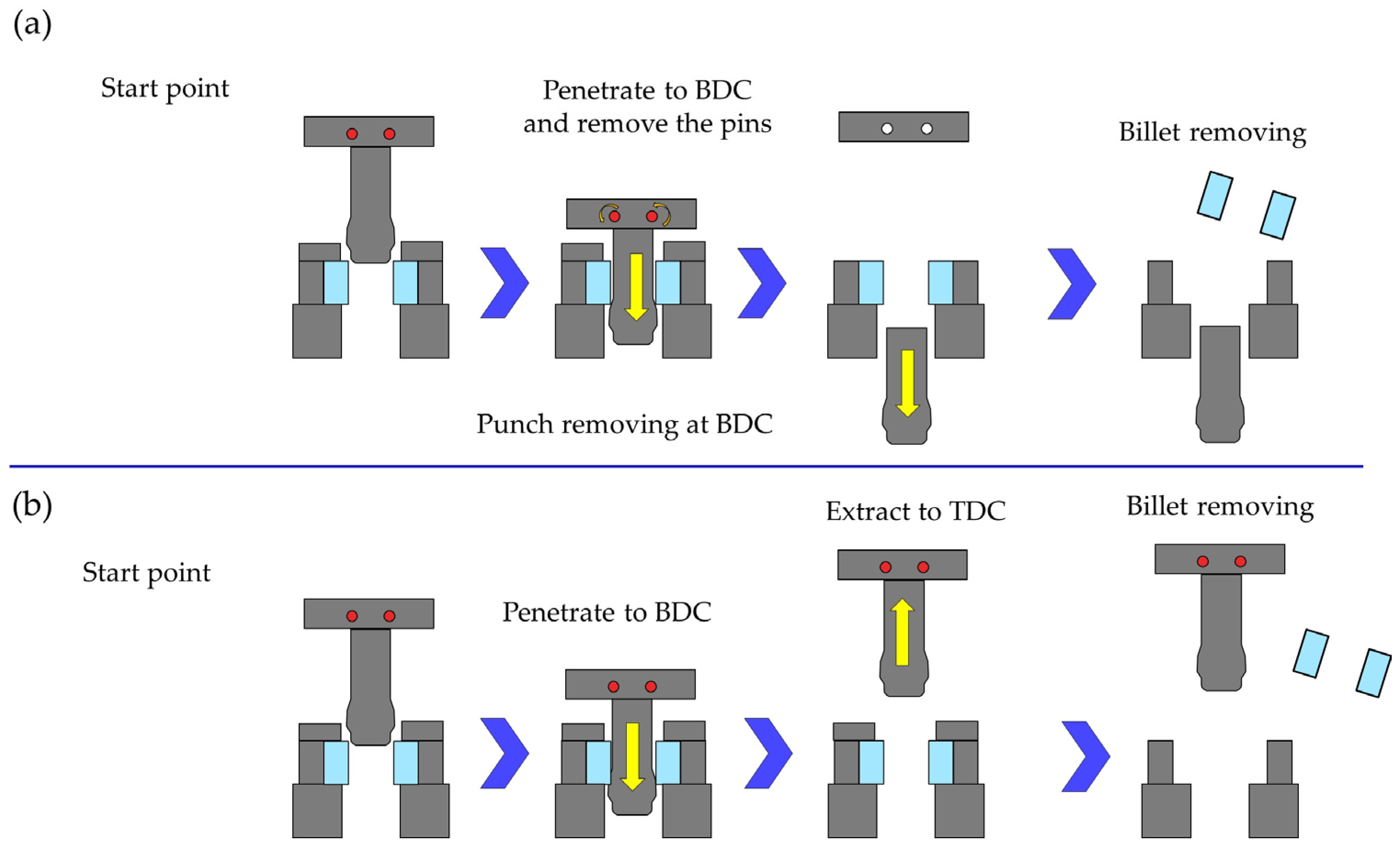
2.1. Characteristics of Extrusion and Lubrication Under Pulsating Motion

The evolution of the lateral extrusion of an internal gear, produced by penetrating the punch with a gear-shaped head into the ring billet, is shown in Figure 1. When the punch penetrates into the ring-shaped billet, the material deforms and moves from the attachment of the punch teeth to the punch grooves in radial (lateral) and axial direction, producing the internal gear grooves and teeth, respectively. On the other hand, the punch teeth attach to the grooves of the internal gear, and the material moved from the internal gear grooves fills the punch grooves, generating the teeth of the internal gear.
The mechanism of the relubrication phenomenon generated by using pulsating motion with liquid lubricant for friction reduction in the lateral extrusion of an internal gear is illustrated in Figure 2. When the punch penetrates into the billet, the liquid lubricant from the punch teeth moves downward and laterally, following the material flow. This displaced liquid lubricant accumulates on the surface of the generated internal gear teeth. In the next step, during the punch’s upward motion, the accumulated liquid lubricant on the internal gear shifts to the side body of the punch teeth, regenerating the lubricant layer in the contact region between the punch teeth and the internal gear grooves.
The designed experimental setup for the lateral extrusion of the internal gear is illustrated in Figure 3. The internal gear is formed by pushing a gear-shaped punch through a cylindrical billet. The die consists of an upper part attached to the press ram, which includes a punch and a punch holder, and a lower stationary part fixed to the press bolster, which consists of a billet holder and a lid. Strain gauges were attached to the body of the punch to measure the forming force during the lateral extrusion of the internal gear. Since the strain gauge measures the elongation of the attached region, it is not possible to determine whether the change is due to tension, compression, or bending. Therefore, four strain gauges were attached around the punch. They were arranged in a two-by-two parallel configuration to compensate for possible misalignments and to increase the accuracy of the measurement.
The procedure for lateral extrusion of the internal gear using only the penetration of the punch, or both penetration and extraction, is illustrated in Figure 4. The die set is designed with a punch lock mechanism. As shown in Figure 4a, when the punch is locked into the punch holder with pins, it penetrates the billet down to the bottom dead center (BDC). At this point, the punch can be removed by taking out the pins and extracting it at BDC. This setup allows the investigation of the internal gear formed solely by the punch penetration. As shown in Figure 4b, if the pins are not removed at BDC and the punch continues moving to top dead center (TDC), it is possible to examine the internal gear formed by both punch penetration and extraction.
The dimensions of the billet, tools, and mechanical properties of the billet, punch, and lubricants are illustrated in Figure 5 and Table 1, respectively. The billet was made of spheroidized annealed S10C in JIS standards, with a hardness of 105 HV10, a height of 19.0 mm, and outer and inner diameters of 39.25 mm and 19.6 mm, respectively. The punch was made of DRM2 high-speed steel (HSS) and had a gear-shaped head with 18 teeth and a module of 1.16. The types of lubricants used included just a solid lubricant (Nippon Parkerizing Co., Ltd., FL-E740, Tokyo, Japan) in a set of tests, and combination of solid lubricant as the undercoat and liquid lubricant containing a sulfur additive in an oil-based solution (Nihon Kohsakuyu Co., Ltd., CF-870, Tokyo, Japan) as overcoat, which has a kinematic viscosity of 132 mm²/s at 40 °C. This liquid lubricant was applied to the inner surface of the billet immediately before conducting the tests on solid lubricants.

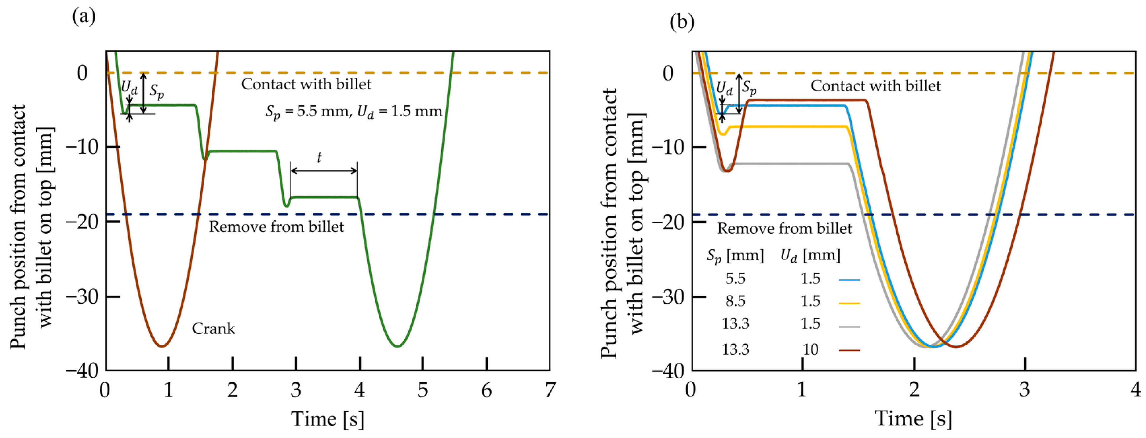
2.2. Motion Parameters Used in the Lateral Extrusion of Internal Gear

The slide motions and parameters with and without pulsation, used for the lateral extrusion of an internal gear performed by the press machine, are shown in Figure 6 and Table 2, respectively. For the condition without pulsation, the crank motion was applied with an average slide speed of 67 mm/s. In contrast, for the condition with pulsation, experiments were conducted with different pulsation counts of n = 3 and n = 1 with an average slide speed of 49 mm/s and slide stop time of 1 s.
The number of pulsations is generally determined based on the regeneration of the lubricant film, which contributes to reducing the forming load. As the punch penetrates the billet, the contact surface area increases, leading to the gradual breakdown of the lubricant film. Each pulsation aids in restoring this film. Taller workpieces typically require more pulsations due to greater contact and deformation. In this study, the initial number of pulsations was selected through a preliminary comparison between the pulse number of n = 3 and higher pulsation counts. The results showed no significant differences in forming loads; therefore, n = 3 were selected for investigations. Subsequently, a single pulsation n = 1 was applied using the same pulse start position Sp = 5.50 mm and upward motion Ud = 1.5 mm as for n = 3, and a comparable reduction in forming load was achieved that showed this condition was suitable for comparing the influence of different pulse number on the shape of laterally extruded internal gears. In the next stage, the pulse start position was shifted closer to the bottom dead center to investigate its effect, ranging from Sp = 5.50 mm to 13.30 mm, on forming load and the final shape of the internal gears under a constant upwards motion Ud = 1.5 mm. Finally, the effect of a larger upward motion Ud = 10 mm at Sp = 13.30 mm was studied to evaluate its influence on relubrication and gear shape in lateral extrusion.

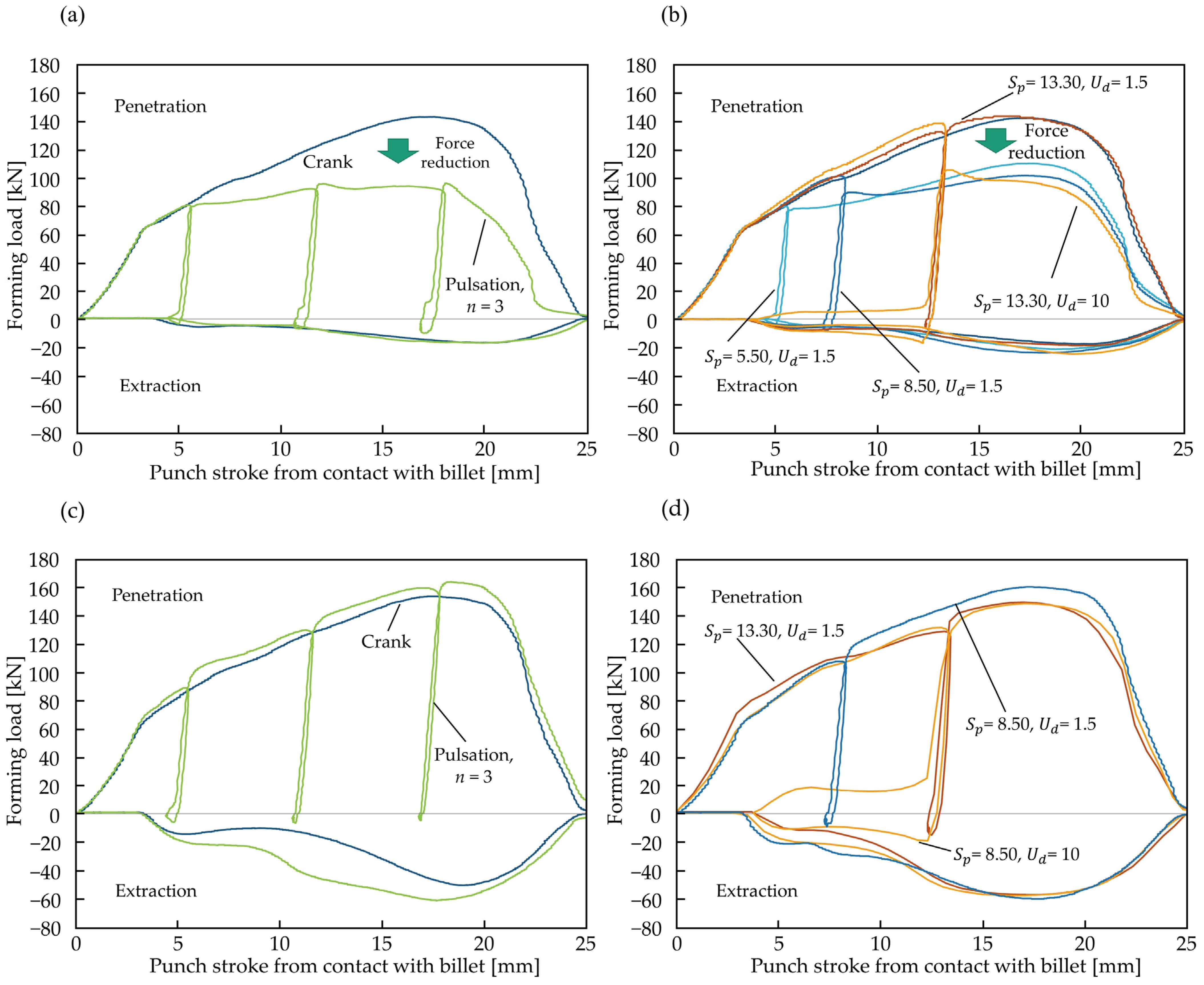
3. Effect of Pulsating Motion on Forming Load

The forming load-stroke curves for the lateral extrusion of internal gears with crank and pulsating motion, using a liquid lubricant over a base solid lubricant, and applying only a solid lubricant, are shown in Figure 7. Figure 7a,b presents the forming load-stroke curves when a liquid lubricant is applied over the solid lubricant, while Figure 7c,d presents the results obtained while using only a solid lubricant for comparison.
The forming load for crank motion and pulsating motion with n = 3 using liquid lubricant over solid lubricant is depicted in Figure 7a. During penetration, the forming load reaches approximately 150 kN in crank motion, whereas in pulsating motion with n = 3, it is about 100 kN. This reduction in force is attributed to the relubrication occurring in pulsating motion when using the liquid lubricant, which does not occur in crank motion. Moreover, when only a solid lubricant is used, as shown in Figure 7c, the absence of a liquid relubrication medium prevents any reduction in force. Consequently, the forming load remains nearly the same between crank motion and pulsating motion with n = 3.
Figure 7b illustrates the forming load–stroke curves for pulsating motion with n = 1, considering different pulse start positions Sp = 5.5, 8.30, and 13.30 mm and pulse upward motions Ud = 1.5 and 10 mm, using a liquid lubricant over a solid lubricant. In the cases of Sp = 5.5 mm and Sp = 8.30 mm with Ud = 1.5 mm, the forming load during punch penetration reaches approximately 100 kN, which is lower than the 150 kN observed in crank motion. This confirms that relubrication occurs even with the lowest pulse count, n = 1. However, before the pulse start position, the forming load for Sp = 8.30 mm is higher than for Sp = 5.5 mm. This is due to the larger surface expansion before the pulse starts, which increases the forming load. After the pulse initiation, the upward motion of Ud = 1.5 mm is sufficient to regenerate the lubricant film for Sp = 5.5 mm and Sp = 8.30 mm, thereby reducing friction between the punch and billet and decreasing the forming load during the subsequent downward stroke.
In contrast, for Sp = 13.30 mm, the forming load before the pulse start continues to increase due to further surface expansion. Following the upward motion of Ud = 1.5 mm, no load reduction occurs, indicating that Ud = 1.5 mm is insufficient to rebuild the lubricant film at this deeper position. As a result, friction increases, and a higher forming load is observed. However, increasing Ud from 1.5 mm to 10 mm at Sp = 13.30 mm leads to a noticeable reduction in forming load. The larger upward motion effectively restores the broken lubricant film, reducing friction and thereby lowering the forming force. This reduction is attributed to the relubrication effect caused by pulsating motion with a liquid lubricant, whereas no relubrication occurs when using only a solid lubricant, as shown in Figure 7d.
The forming load during extraction, when using a liquid lubricant over a solid lubricant, reaches 15–22 kN, as shown in Figure 7a,b. In contrast, when only a solid lubricant is used, as shown in Figure 7c,d, the extraction force increases to 50–60 kN, which is significantly higher than that in lateral extrusion forging with a liquid lubricant. This reduction in extraction force with liquid lubricant is attributed to the presence of a liquid lubricant film between the punch and billet. Since the large plastic deformation occurs during penetration, the extraction force remains relatively low in this condition. However, when only a solid lubricant is used, the absence of a liquid lubricant film between the punch and billet results in higher friction and higher extraction force.

4. Effect of Pulsating Motion Parameters on the Shape of Laterally Extruded Internal Gear

The internal gear formed by lateral extrusion forging from a ring-shaped billet is illustrated in Figure 8. During the process, the billet is transformed into an internal gear, with material separated from the bottom as burr. The formed gear features tooth grooves shaped by direct contact of the punch teeth, while the generated gear teeth result from the deformation of the material within the punch grooves. The internal gear grooves have a flat surface due to their direct contact with the punch teeth. In contrast, the laterally extruded gear teeth formed in the punch grooves consist of three distinct regions from top to bottom: a deep, incompletely filled area at the top, a fully filled region limited to the punch groove, and another shallow, incompletely filled area at the bottom. The outside diameter of the formed internal gear increases until it is limited by the billet holder, as shown in Figure 3. Additionally, the height of the formed internal gear increases compared to the initial height of the billet.

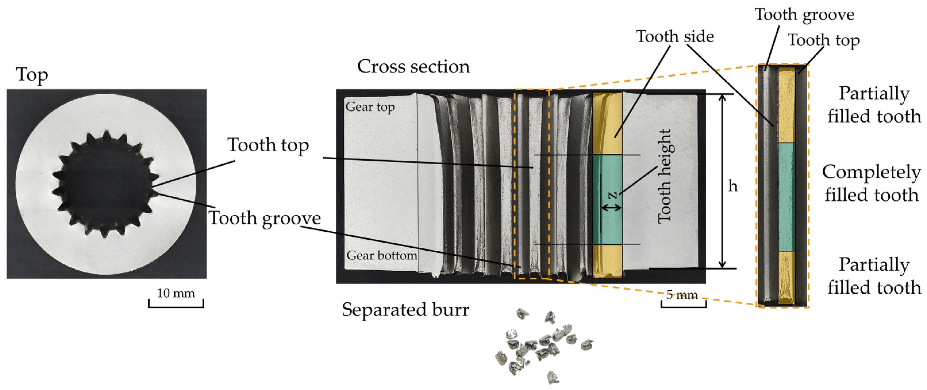
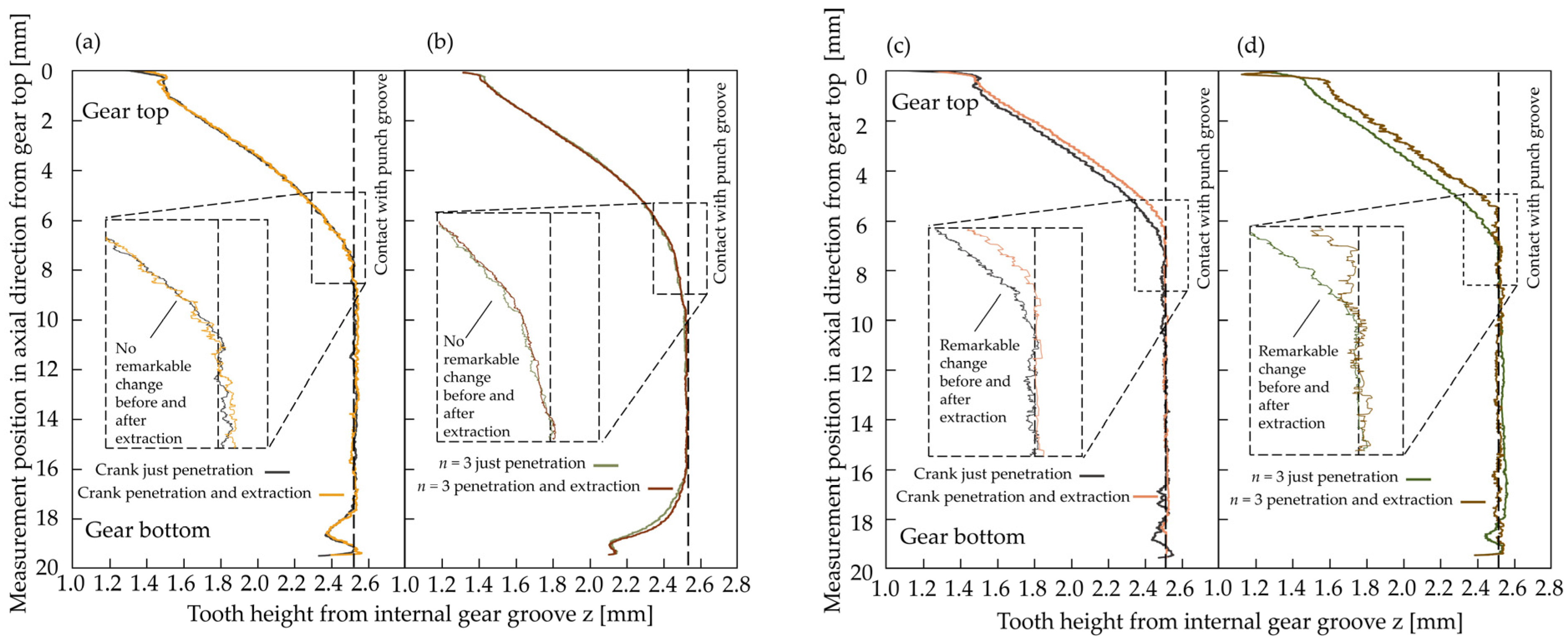
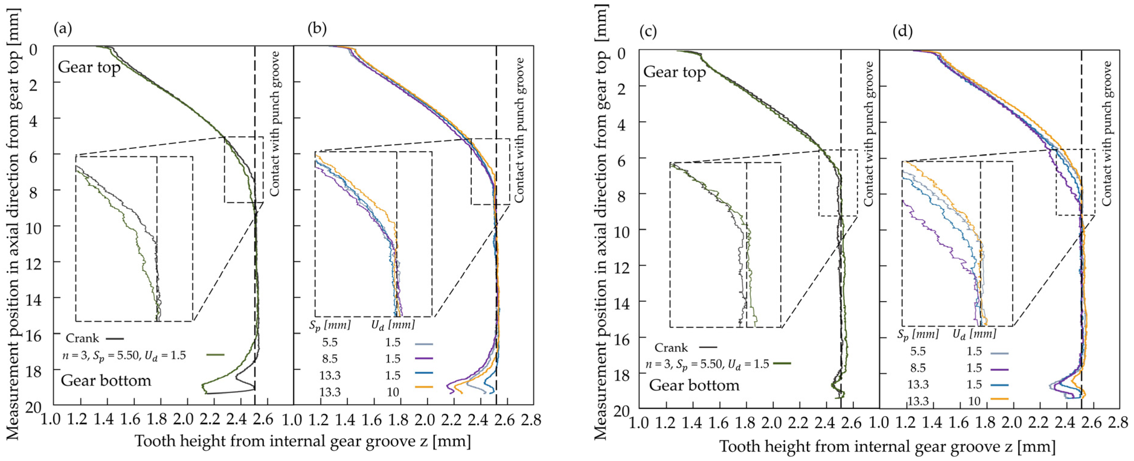
4.1. Height Distribution of Generated Teeth in the Lateral Extrusion of Internal Gear

To evaluate the height distribution of the generated teeth, the distance from the groove bottom to the top of each tooth was measured using a microscope. Figure 9 presents the resulting tooth height distribution, comparing two punch motions, crank and pulsating motion with n = 3, under conditions of punch penetration alone and penetration followed by extraction. The analysis was conducted using both a liquid-over-solid lubricant and a solid lubricant alone. As shown in Figure 9a,b, the change in tooth height before and after extraction with liquid lubricant is negligible, indicating minimal material flow during extraction. This observation aligns with the low extraction load of approximately 20 kN shown in Figure 7a. In contrast, when only solid lubricant is used (Figure 9c,d), a significant difference in tooth height is observed between penetration alone and penetration followed by extraction, suggesting upward material flow. This corresponds with the higher extraction load of 40–60 kN shown in Figure 7c. The focus in the next step was only on the effect of pulsating motion. Therefore, investigations and measurements were conducted on laterally extruded internal gears formed only by punch penetration, eliminating the influence of the extraction phase. This allows for a comparison of how different motion parameters that affect forming load during penetration influence the resulting tooth height. In Figure 10a, the tooth height distribution is shown for crank motion and pulsating motion with n = 3, while Figure 10b illustrates results for pulsating motion with n = 1, using various pulse start positions Sp and pulse upward movements Ud during forging with liquid lubricant over solid lubricant, where a relubrication effect is present. Figure 10c,d shows the height distributions for crank and pulsating motions using only solid lubricant, without the relubrication effect, enabling a comparison with tests involving liquid lubrication, where both relubrication and reduced forming load occur. The diagram showing the gear tooth with the partially or completely filled area of the teeth formed by the lateral extrusion of the internal gear, based on data from Figure 10, is presented in Figure 11. The generated teeth exhibit partially unfilled regions at both the top and bottom of the gear, while the middle section is fully filled and in contact with the punch groove surface. Figure 11a shows the results obtained using liquid lubricant, whereas Figure 11b illustrates the results when only solid lubricant is used. The filled area in pulsating motion n = 3 is less than that with crank motion using liquid lubricant. On the other hand, in pulsating motion n = 3 with liquid lubricant, where relubrication occurs and the magnitude of friction is reduced, the filled area is reduced in comparison with crank motion without relubrication and without reduction in friction. Moreover, in pulsating motions of n = 1 with pulse start positions of Sp = 5.5, 8.5, and 13.3 mm, as the pulse start position approaches the bottom of the gear and as the maximum forming load increases and friction increases, the filled area of the generated tooth of the internal gear increases. On the other hand, although relubrication causes a reduction in forming load and friction, it has the opposite effect on achieving a completely filled generated tooth.

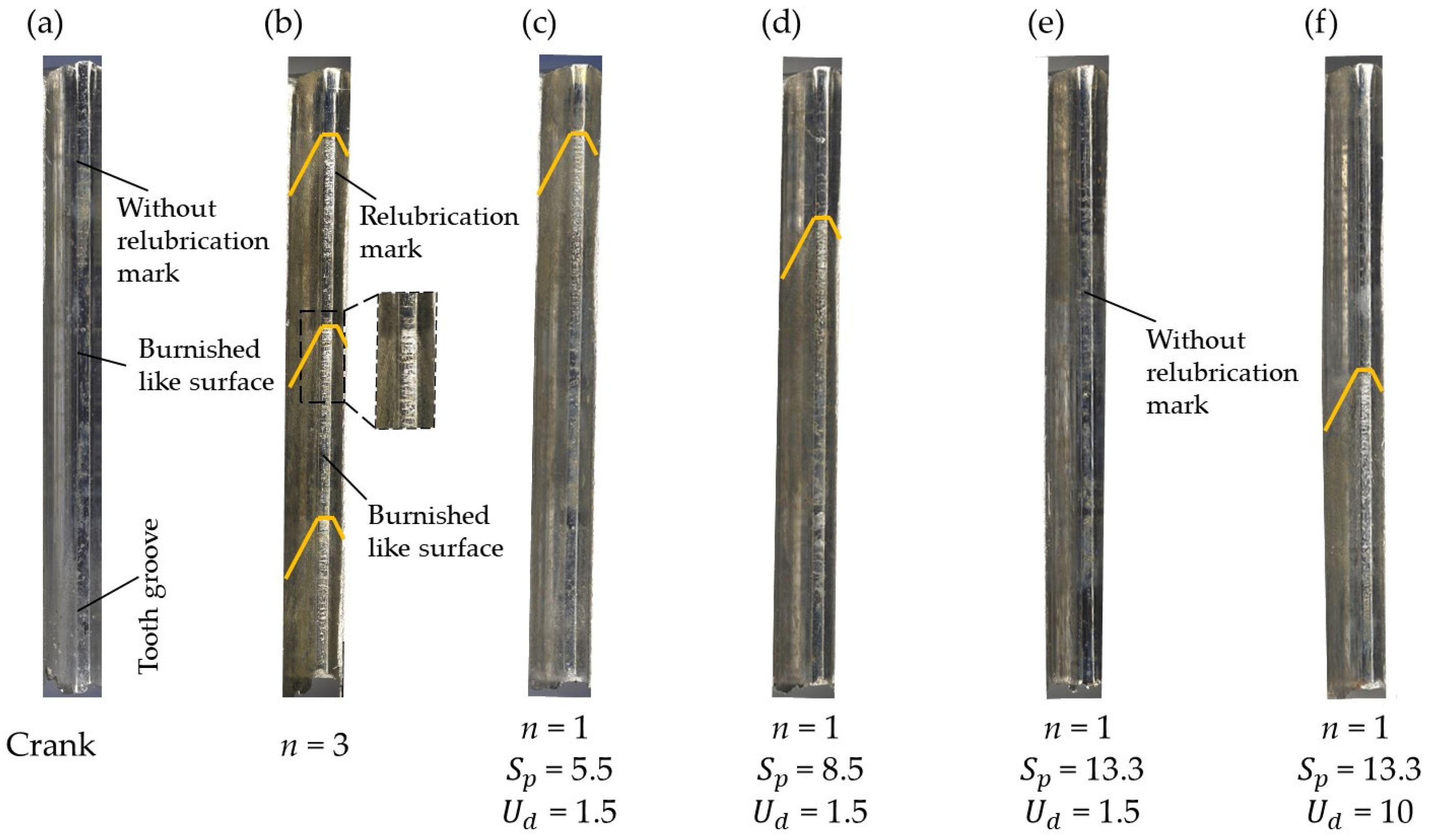
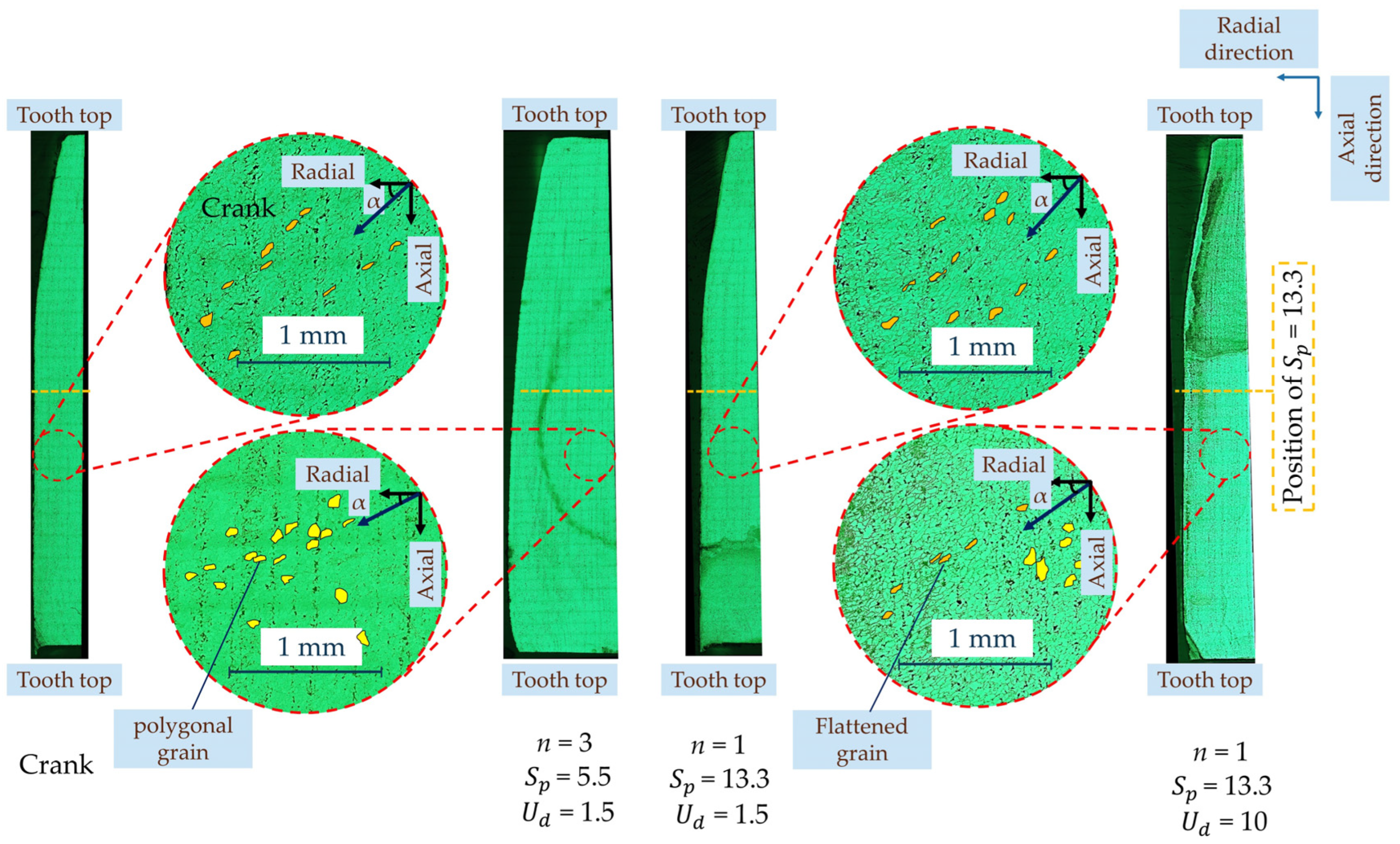
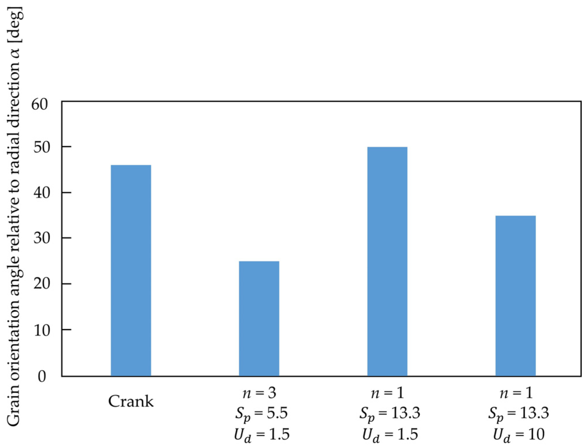
4.2. Groove Surface of Generated Teeth in the Lateral Extrusion of Internal Gear

The surface condition at the groove of the gear tooth under liquid lubricant with crank and pulsating motions is shown in Figure 12. In crank motion, relubrication does not occur, resulting in the entire root surface appearing uniformly burnished. In contrast, when using pulsating motions with n = 3 and n = 1, and pulse start positions Sp = 5.5 and 8.5 mm with an upward displacement Ud = 1.5 mm, as well as at Sp =13.3 mm with Ud = 10 mm relubrication occurs and the marks corresponding to each pulse are clearly distinguishable. However, at a pulse start position of Sp = 13.3 with a smaller upward motion Ud = 1.5, relubrication does not take place, and no relubrication marks are observed.

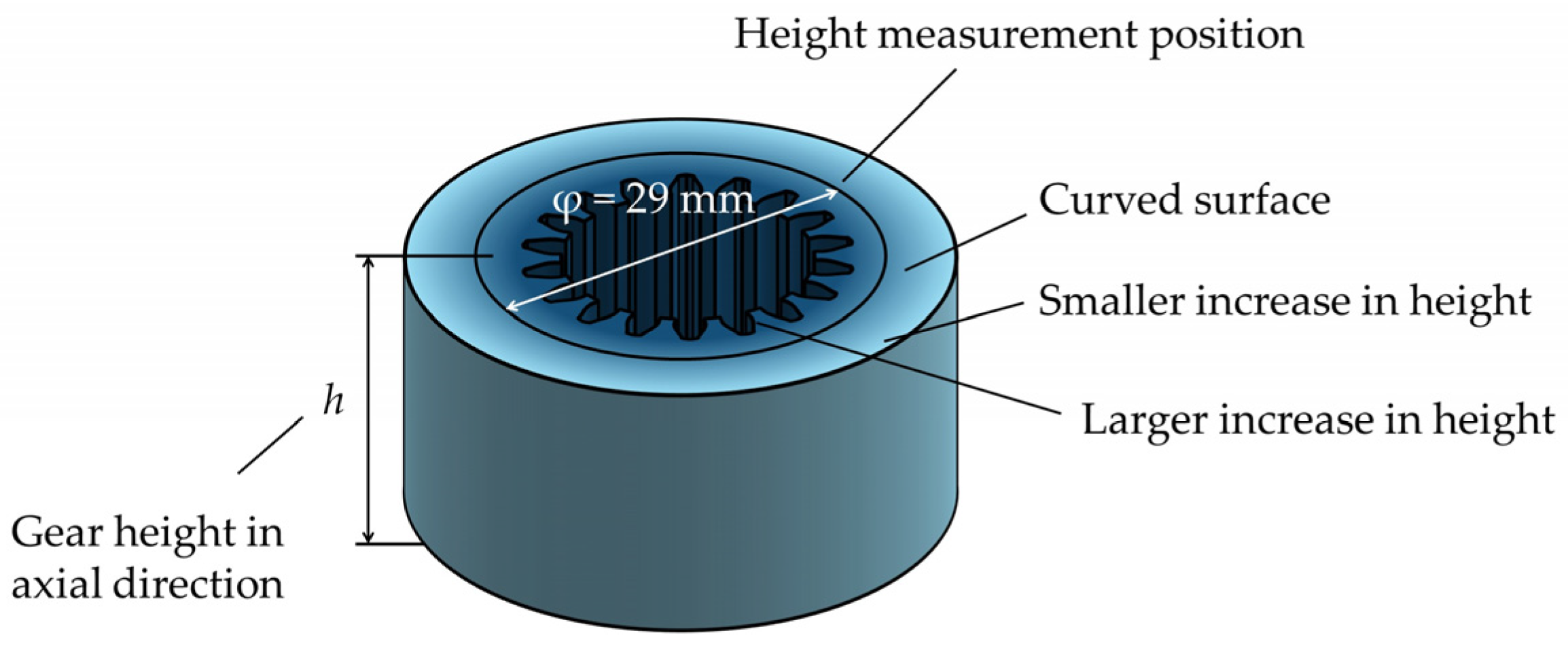
4.3. Height of Gear in the Lateral Extrusion of Internal Gear

The height of the laterally extruded internal gear increases compared to the initial billet height. As shown in Figure 13, this increase is not uniform. It is smaller around the outer circumference of the internal gear and greater around the generated teeth. To compare the height increase during forging under different punch motions, measurement positions were picked on a circle of 29 mm. The height increase in the forged internal gear, using liquid lubricant over solid lubricant and solid lubricant alone, is presented in Figure 14.
In crank motion, the increase in height is less than that observed in pulse motion with n = 3. On the other hand, pulse motion using liquid lubricant, which promotes relubrication and reduces forming load, results in a forged internal gear with greater height. In pulsating motion n = 1, pulse start positions Sp = 5.5 and 8.5 mm, and upward motion Ud = 1.5 mm, where relubrication occurs, the increased height exceeds that of crank motion, which lacks relubrication. Furthermore, at Sp = 13.30 mm and Ud = 1.5 mm, where relubrication does not occur, the height increase is lower than under conditions where relubrication is present. However, at Sp = 13.30 mm and Ud = 10 mm, where relubrication occurs, the increase in height is comparable to that of n = 3 with relubrication. Additionally, in forging with only solid lubricant, where relubrication does not occur, the height increase under pulsating motion is greater than in crank motion, though not as substantial as in forging with liquid lubricant and relubrication.

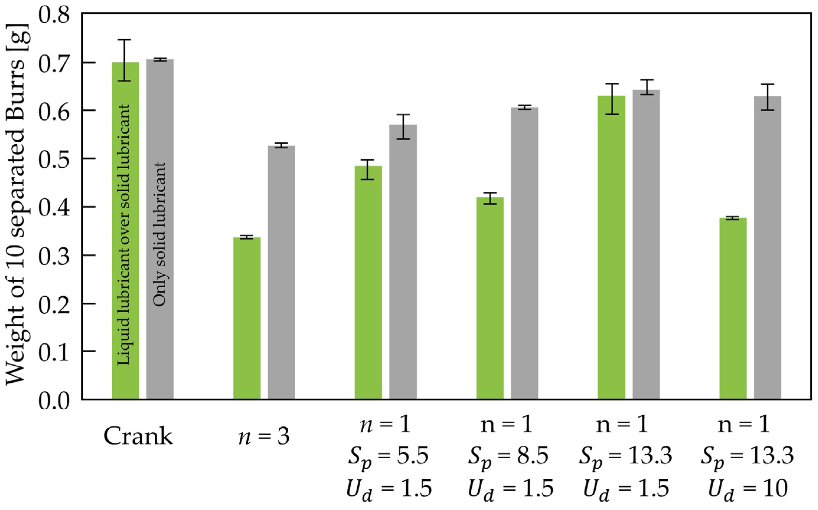
4.4. Weight of Separated Burr Generated During the Lateral Extrusion of Internal Gear

In addition to dimensional measurements, the weight of separated burrs generated during the lateral extrusion of the internal gear was also evaluated to assess deformation. These measurements were carried out for different motion types using both liquid and solid lubricants, as shown in Figure 15. Since it was difficult to measure the weight of each individual separated burr, the total weight of 10 collected burrs was measured using an electronic balance (TW423N, Shimadzu, Kyoto, Japan). The average burrs weight in crank motion was approximately 0.7 g. In contrast, during pulsating motion with n = 3 using liquid lubricant, the burr weight decreased significantly to about 0.34 g. Similarly, in pulsating motion with n = 1, under conditions such as Sp = 5.5 and 8.5 with Ud = 1.5, where relubrication occurs due to the use of liquid lubricant, burr weight was also reduced, comparable to that of n = 3. Moreover, in pulsating motion without liquid lubricant where relubrication does not occur the burr weight was higher than in conditions with relubrication.

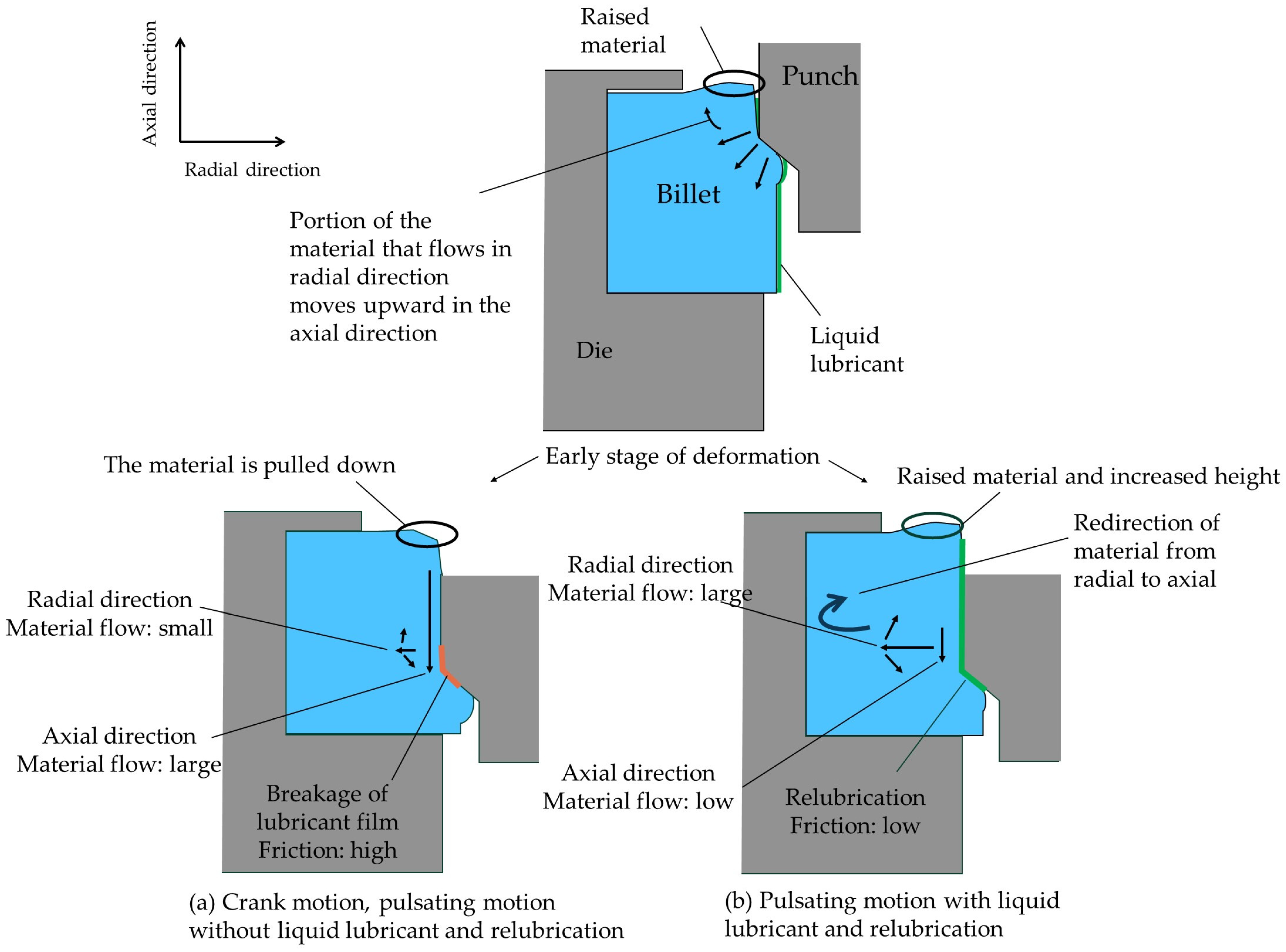
5. Change in Material Flow During the Lateral Extrusion of Internal Gear with and Without Relubrication Effect

The obtained results for generated tooth-filled area, gear height, and burr size indicate that material flow in both axial and radial directions is influenced by the frictional condition between the punch and billet, which is affected by punch motion and relubrication, as shown in Figure 16. As the punch penetrates the billet, the material flows axially downward and radially from the contact points of the punch teeth toward the punch grooves. In crank motion, as well as in pulsating motion without liquid lubricant, high friction between the punch teeth and billet causes material to adhere between the generated tooth and punch grooves with a larger tooth-filled area and under the punch head. As the punch continues to descend, the accumulated material beneath the punch head is eventually sheared off, forming large burrs.
In contrast, during pulsating motion with relubrication, where friction is reduced, the material behavior changes. In the pulse start position region, reduced axial friction decreases the amount of material trapped between the generated gear tooth and punch grooves and reduces accumulation under the punch land. As a result, the tooth-filled area is smaller, and in the later stage of deformation, smaller burrs are formed while material primarily flows radially. Additionally, radial material flow is relatively enhanced compared to the axial direction. Once confined by the die in radial direction, the radially displaced material is redirected axially, leading to an increase in gear height.
To confirm the validity of the proposed model of material flow during the lateral extrusion of internal gear, both with and without the effect of relubrication, the cross-section of the generated teeth was cut, polished, etched, and observed to analyze the grain structure. This analysis was conducted to validate the proposed material flow model.
Figure 17 illustrates the cross-section of an extruded gear tooth produced using both crank and pulsating motions with liquid lubrication. In these cross-sections, when plastic deformation is not large, the grains exhibit a polygonal shape. However, in regions subjected to greater plastic deformation, the grains become elongated and their orientation shifts in the direction of material flow.
To compare the direction of material flow, a point between the middle and bottom of the formed tooth after the pulse start position of Sp = 13.30 mm on the dedendum was selected. This area was selected since, as shown in Figure 7a,b, there is a remarkable difference in forming load in conditions with relubrication and without relubrication, which influences the shape of the generated tooth. The angle between the material flow direction and the radial direction was measured. A smaller angle indicates stronger material flow in the radial direction, while a larger angle suggests reduced radial flow.
The grain orientation angles relative to the radial direction, obtained from the forging process under different motion conditions in Figure 17, are presented in Figure 18. The difference in grain direction angle between crank motion, which represents the condition without relubrication, and pulsating motion at n = 3, which represents the condition with relubrication, supports the validity of the proposed material flow model for the lateral extrusion of internal gears. Furthermore, the elongation observed in pulsating motion at n = 1, with the same pulse start position of Sp = 13.3 mm and different upward displacements of Ud = 1.5 mm and 10 mm, corresponding to conditions without and with relubrication, respectively shows a trend consistent with that observed in crank motion and pulsating motion at n = 3.

6. Conclusions

To meet environmental requirements by eliminating phosphate conversion coating in the forging process, pulsating motion has proven to be effective. This study investigated the lateral cold extrusion forging of an internal gear using pulsating motion. A specially designed die set with a removable punch enabled the observation of material flow both before and after punch extraction, allowing a detailed analysis of how pulsating motion parameters influence relubrication, forming load, and the final gear geometry. The key findings are as follows:
  • Pulsating motion in the presence of a liquid lubricant effectively reduced the forming load during punch penetration. In contrast, when liquid lubricant was absent, relubrication did not occur, and no reduction in forming load was observed.
  • With liquid lubrication, the forming load during punch extraction was significantly reduced, resulting in negligible material flow. However, without a liquid lubricant, the extraction force increased considerably, leading to notable changes in material flow.
  • Relubrication was observed even with a single pulsation, n = 1, which shortens the overall forming time compared to n = 3. However, achieving effective relubrication and load reduction still requires a careful optimization of pulsating motion parameters.
  • The pulse start position significantly influenced the effectiveness of relubrication. At lower start positions (e.g., Sp = 5.5 mm), even a small upward motion Ud = 1.5 mm was sufficient to rebuild the lubricant film and reduce the forming load. However, at a higher pulse start position, Sp = 13.3 mm, the same upward motion was inadequate, resulting in insufficient relubrication and higher forming loads. Increasing the upward motion Ud = 10 mm at Sp = 13.3 mm successfully restored the lubricant film and reduced the forming load.
  • Although relubrication due to pulsating motion reduced the forming load, it also resulted in less complete filling of the generated gear teeth, which may be considered a drawback depending on the application requirements.
  • Internal gears produced under conditions that enabled relubrication exhibited greater tooth height compared to those formed without relubrication, indicating improved material flow in the axial direction.

Author Contributions

Conceptualization, A.S. and T.M.; methodology, A.S. and T.M.; software, A.S.; validation, A.S., T.M.; investigation, A.S.; resources, T.M.; data curation, A.S.; writing—original draft preparation, A.S.; writing—review and editing, A.S., T.M.; visualization, A.S.; supervision, T.M.; project administration, T.M.; funding acquisition, T.M. All authors have read and agreed to the published version of the manuscript.

Funding

This research received no external funding.

Institutional Review Board Statement

Not applicable.

Informed Consent Statement

Not applicable.

Data Availability Statement

Data available on request due to restrictions related to the author’s ongoing research. The data are not publicly shared at this time, but may be provided upon reasonable request at the discretion of the corresponding author.

Acknowledgments

The authors sincerely thank Shiga and Furukawa of SUBARU CORPORATION, as well as Mashu Takahashi, for their dedicated support and valuable assistance throughout the research, including die preparation and development of the research process.

Conflicts of Interest

The authors declare no conflict of interests.

References

  1. Plancak, M.; Bramley, A.; Osman, F. Non-conventional cold extrusion. J. Mater. Process Technol. 1992, 34, 465–472. [Google Scholar] [CrossRef]
  2. Petersen, S.B.; Balendra, R.; Rodrigues, J.M.C.; Martins, P.A.F. The avoidance of defects in radially extruded tubular parts by preforming. J. Mater. Process Technol. 1997, 69, 155–161. [Google Scholar] [CrossRef]
  3. Can, Y.; Altınbalık, T.; Akata, H.E. A study of lateral extrusion of gear-like elements and splines. J. Mater. Process Technol. 2005, 166, 128–134. [Google Scholar] [CrossRef]
  4. Jafarzadeh, H.; Faraji, G.; Dizaji, A.F. Analysis of lateral extrusion of gear-like form parts. J. Mech. Sci. Technol. 2012, 26, 3243–3252. [Google Scholar] [CrossRef]
  5. Altinbalik, T.; Ayer, Ö. Finite Element Analysis of Gear Like Form by Using Lateral and Forward Extrusion. Proc. Trakya Univ. Eng. Fac. Conf. 2014, 3, 140–147. [Google Scholar] [CrossRef]
  6. Bay, N. The state of the art in cold forging lubrication. J. Mater. Process Technol. 1994, 46, 19–40. [Google Scholar] [CrossRef]
  7. Dohda, K.; Yamamoto, M.; Hu, C.; Dubar, L.; Ehmann, K.F. Galling phenomena in metal forming. Friction 2021, 9, 665–685. [Google Scholar] [CrossRef]
  8. Bay, N.; Azushima, A.; Groche, P.; Ishibashi, I.; Merklein, M.; Morishita, M.; Nakamura, T.; Schmid, S.; Yoshida, M. Environmentally benign tribo-systems for metal forming. CIRP Ann. 2010, 59, 760–780. [Google Scholar] [CrossRef]
  9. Sagisaka, Y.; Ishibashi, I.; Nakamura, T.; Sekizawa, M.; Sumioka, Y.; Kawano, M. Evaluation of environmentally friendly lubricants for cold forging. J. Mater. Process Technol. 2012, 212, 1869–1874. [Google Scholar] [CrossRef]
  10. Wang, Z.G.; Komiyama, S.; Yoshikawa, Y.; Suzuki, T.; Osakada, K. Evaluation of lubricants without zinc phosphate precoat in multi-stage cold forging. CIRP Ann. 2015, 64, 285–288. [Google Scholar] [CrossRef]
  11. Oshita, K.; Komiyama, S.; Sasaki, S. Effects of surface texturing pattern on the lubricity of mica-organic hybrid solid lubricants and parametric evaluation of their cleavabilities. Tribol. Int. 2019, 140, 105842. [Google Scholar] [CrossRef]
  12. Volz, S.; Launhardt, J.; Bay, N.; Hu, C.; Moreau, P.; Dubar, L.; Nielsen, C.; Hayakawa, K.; Kitamura, K.; Groche, P. International round robin test of environmentally benign lubricants for cold forging. CIRP Ann. 2023, 72, 245–250. [Google Scholar] [CrossRef]
  13. Osakada, K.; Mori, K.; Altan, T.; Groche, P. Mechanical servo press technology for metal forming. CIRP Ann. 2011, 60, 651–672. [Google Scholar] [CrossRef]
  14. Maeno, T.; Osakada, K.; Mori, K. Reduction of friction in compression of plates by load pulsation. Int. J. Mach. Tools Manuf. 2011, 51, 612–617. [Google Scholar] [CrossRef]
  15. Matsumoto, R.; Sawa, S.; Utsunomiya, H.; Osakada, K. Prevention of galling in forming of deep hole with retreat and advance pulse ram motion on servo press. CIRP Ann. 2011, 60, 315–318. [Google Scholar] [CrossRef]
  16. Ishikawa, T.; Ishiguro, T.; Yukawa, N.; Goto, T. Control of thermal contraction of aluminum alloy for precision cold forging. CIRP Ann. 2014, 63, 289–292. [Google Scholar] [CrossRef]
  17. Matsumoto, R.; Jeon, J.Y.; Utsunomiya, H.; Osakada, K. Shape accuracy in the forming of deep holes with retreat and advance pulse ram motion on a servo press. J. Mater. Process Technol. 2013, 213, 770–778. [Google Scholar] [CrossRef]
  18. Matsumoto, R.; Hayashi, K.; Utsunomiya, H. Experimental and numerical analysis of friction in high aspect ratio combined forward-upward extrusion with retreat and advance pulse ram motion on a servo press. J. Mater. Process Technol. 2014, 214, 936–944. [Google Scholar] [CrossRef]
  19. Chen, M.; Hua, L.; Hu, Z.; Dong, K.; Qin, X. Cracking and suppression mechanisms of directed energy deposited IN738 superalloy revealed by microstructural characterization, in-situ thermal monitoring, and numerical simulations. J. Alloys Compd. 2025, 1020, 179446. [Google Scholar] [CrossRef]
  20. Maeno, T.; Mori, K.; Hori, A. Application of load pulsation using servo press to plate forging of stainless steel parts. J. Mater. Process Technol. 2014, 214, 1379–1387. [Google Scholar] [CrossRef]
  21. Groche, P.; Heß, B. Friction control for accurate cold forged parts. CIRP Ann. 2014, 63, 285–288. [Google Scholar] [CrossRef]
  22. Maeno, T.; Mori, K.; Ichikawa, Y.; Sugawara, M. Use of liquid lubricant for upward extrusion of cup with internal splines using pulsating motion. J. Mater. Process Technol. 2017, 244, 273–281. [Google Scholar] [CrossRef]
  23. Maeno, T.; Sugawara, M.; Saito, T.; Terada, A.; Mori, K. Improvement of burnished area in punching of stainless steel thick plate by means of pulsating motion. Procedia Manuf. 2020, 50, 203–209. [Google Scholar] [CrossRef]
  24. Kuo, C.C.; Huang, H.L.; Li, T.C.; Fang, K.L.; Lin, B.T. Optimization of the pulsating curve for servo stamping of rectangular cup. J. Manuf. Process 2020, 56, 990–1000. [Google Scholar] [CrossRef]
  25. Meng, D.; Zhu, C.; Zhao, X.; Zhao, S. Applying low-frequency vibration for the experimental investigation of clutch hub forming. Materials 2018, 11, 928. [Google Scholar] [CrossRef]
  26. Müller, P.; Hübner, S.; Rosenbusch, D.; Vogt, H.; Behrens, B.A. Investigation of the influence of a superimposed oscillated forming process on forming characteristics. Key Eng. Mater. 2021, 883, 181–186. [Google Scholar] [CrossRef]
  27. Ben, N.Y.; Zhang, Q.; Bandyopadhyay, K.; Lee, M.G. Analysis of friction behavior under oscillating forming process using T-shape compression test and finite element simulation. J. Mater. Process Technol. 2020, 275, 116327. [Google Scholar] [CrossRef]
  28. Groche, P.; Schmidt, W. Wear prediction in oscillating cold forging processes. Tribol. Lett. 2020, 68, 128. [Google Scholar] [CrossRef]
  29. Matsumoto, R.; Utsunomiya, H.; Ishigai, S. Lubrication in hot forging with pulsed ram motion. Key Eng. Mater. 2018, 767, 149–156. [Google Scholar] [CrossRef]
  30. Zhang, Q.; Ben, N.Y.; Yang, K. Effect of variational friction and elastic deformation of die on oscillating cold forging for spline shaft. J. Mater. Process Technol. 2017, 244, 166–177. [Google Scholar] [CrossRef]
  31. Matsumoto, R.; Nakamura, Y.; Utsunomiya, H. In situ observation of re-lubrication of die–workpiece interface during forging with ram pulsation. J. Manuf. Process 2023, 101, 675–686. [Google Scholar] [CrossRef]
Figure 1. The evolution of the lateral extrusion of an internal gear, produced by penetrating the punch with a gear-shaped head into the ring-shaped billet, (a) before penetration of the punch into the ring billet and (b) during penetration of the punch into the ring billet.
Jmmp 09 00190 g001
Figure 2. Mechanism of relubrication phenomenon generated by using pulsating motion with applied liquid lubricant for friction reduction in the lateral extrusion forging of internal gear, (a) before forging, (b) early stage of forging, (c) forging with large plastic deformation during the downward motion of punch and (d) upward ward motion of punch.
Jmmp 09 00190 g002
Figure 3. Designed experimental setup for laterally extrusion of internal gear, (a) overall view, (b) assembled on press machine.
Jmmp 09 00190 g003
Figure 4. Procedure of the lateral extrusion forging of internal gear; (a) forging with just penetration and (b) forging with both penetration and extraction.
Jmmp 09 00190 g004
Figure 5. (a) Dimensions of billet, and (b) billet holder and punch used in the lateral extrusion of internal gear.
Jmmp 09 00190 g005
Figure 6. Slide motion curves with and without pulsation used for the lateral extrusion of internal gear, (a) crank motion and pulsation with n = 3, and (b) pulsation of n = 1 with different pulse start positions Sp and upward motion Ud.
Jmmp 09 00190 g006
Figure 7. Forming load–punch stroke curves from the lateral extrusion of internal gears; (a) crank and pulsating motion with n = 3 using liquid lubricant, (b) pulsating motion with n = 1 at different pulse start positions Sp and pulse upward motions Ud using liquid lubricant, (c) crank and pulsating motion with n = 3 using solid lubricant, and (d) pulsating motion with n = 1 at different Sp and Ud using solid lubricant.
Jmmp 09 00190 g007
Figure 8. Appearance of the generated portions of the laterally extruded internal gear from the ring-shaped billet.
Jmmp 09 00190 g008
Figure 9. Height distribution of the generated teeth during the lateral extrusion of the internal gear under punch motions involving penetration only and penetration followed by extraction. (a) Crank motion with liquid lubricant over solid lubricant, (b) pulsating motion n = 3 with liquid lubricant over solid lubricant, (c) crank motion with solid lubricant only, and (d) pulsating motion n = 3 with solid lubricant only.
Jmmp 09 00190 g009
Figure 10. Height distribution of generated teeth in the lateral extrusion of internal gear using different motions with just penetration of the punch. (a) Crank motion and pulsating motion of n = 3 using liquid lubricant on solid lubricant, (b) pulsating motion of n = 1 using liquid lubricant on solid lubricant, (c) crank motion and pulsating motion of n = 3 with only solid lubricant and (d) pulsating motion of n = 1 with only solid lubricant.
Jmmp 09 00190 g010
Figure 11. Diagram of the partially or completely filled area of teeth formed by the lateral extrusion of the internal gear under different motion conditions; (a) using liquid lubricant over solid lubricant, and (b) using only solid lubricant.
Jmmp 09 00190 g011
Figure 12. Surface of the tooth groove of laterally extruded internal gears using liquid lubricant over solid lubricant under different punch motions with only punch penetration. (a) Crank motion, (b) pulsating motion with n = 3, (c) pulsating motion with n = 1, Sp = 5.5, and Ud = 1.5 mm, (d) n = 1, Sp = 8.5, and Ud = 1.5 mm, (e) n = 1, Sp = 13.3, and Ud = 1.5 mm, and (f) n = 1, Sp = 13.3, and Ud = 10 mm.
Jmmp 09 00190 g012
Figure 13. Shape of the increased height of the laterally extruded internal gear and the corresponding measurement position.
Jmmp 09 00190 g013
Figure 14. Measured increase in the height of laterally extruded internal gear under different punch motions using liquid lubricant over solid lubricant and solid lubricant alone.
Jmmp 09 00190 g014
Figure 15. Measured weight of 10 burrs separated in the lateral extrusion of internal gear under different punch motions using liquid lubricant over solid lubricant and solid lubricant alone.
Jmmp 09 00190 g015
Figure 16. Material flow in axial and radial directions in the lateral extrusion of internal gear influenced by frictional condition between the punch and billet.
Jmmp 09 00190 g016
Figure 17. Grain shape of generated teeth in laterally extruded internal gears using liquid lubricant under different punch motion conditions.
Jmmp 09 00190 g017
Figure 18. Grain orientation angle relative to radial direction in laterally extruded internal gears using liquid lubricant under different punch motion conditions.
Jmmp 09 00190 g018
Table 1. Properties of billet, tools, and lubricants used for the lateral extrusion of internal gear.
MaterialHardnessSurface Roughness Ra, [μm]
BilletAnnealed mild steel: S10C105 [HV10]1.4
PunchHigh speed steel: DRM256–60 [HRC]0.8
DieTool steel: SK368 [HRC]0.2
Solid lubricantNippon Parkerizing Co., Ltd., FL-E740
Liquid lubricantSulphur additive contained oil-based: v = 132 m m 2 /s at 40 °C
Table 2. Parameters of slide motion with and without pulsation motion used for the lateral extrusion of the internal gear.
Type of Slide MotionNumber of Pulse n [–] Pulse   Start   Position   S p [mm] Upward   Motion   U d [mm] Average Slide Speed [mm/s]
Without Oscillation067
With Oscillation35.501.549
With Oscillation15.501.549
With Oscillation18.301.549
With Oscillation113.301.549
With Oscillation113.301049
Disclaimer/Publisher’s Note: The statements, opinions and data contained in all publications are solely those of the individual author(s) and contributor(s) and not of MDPI and/or the editor(s). MDPI and/or the editor(s) disclaim responsibility for any injury to people or property resulting from any ideas, methods, instructions or products referred to in the content.

