1. Introduction
Cold spraying is a new solid-state material surface deposition process [
1]. During the spraying process, high-temperature compressed gas (typically nitrogen, air, or helium) is used as the propellant gas to accelerate metal particle powders to a high velocity, causing plastic deformation upon impact with the substrate (usually metal), resulting in adhesion to the substrate [
2,
3,
4,
5,
6]. Cold spraying can be categorized into two types: high-pressure cold spraying and low-pressure cold spraying. In low-pressure cold spraying systems, the gas pressure used is typically less than 1 MPa [
7]. Compared to high-pressure cold spraying equipment, low-pressure cold spraying equipment offers advantages such as portability and low consumption, making it widely used in industrial fields such as corrosion mitigation and protection, dimensional restoration, and repair and remanufacturing of castings and molds [
8,
9,
10]. Additionally, it is particularly beneficial for on-site maintenance of equipment in certain areas, such as outdoor military equipment repairs. With the rise of additive manufacturing, cold spraying technology has gained significant attention. Despite the high deposition efficiency of high-pressure cold spraying [
11], it is challenging to precisely control the growth of deposits, and excessive deposition growth can easily lead to collisions with the spray gun [
12,
13,
14]. Moreover, the high cost, significant resource consumption, and limited mobility of high-pressure systems present issues that need to be addressed. As a crucial branch of cold spraying, low-pressure cold spraying, with its simple equipment and low cost, holds significant engineering importance in enhancing its performance.
Despite its advantages in certain aspects, low-pressure cold spraying exhibits inferior deposition performance compared to high-pressure cold spraying. Particularly when applying low-pressure cold spraying technology in the field of additive manufacturing, the low powder deposition efficiency can increase production costs and limit the application of this technology. In the cold spraying process, deposition efficiency is one of the key indicators for measuring process performance, as it directly impacts the quality of the deposition, production costs, and the application scope of the process. Therefore, improving the deposition efficiency of cold spraying has become a focal point of research in this field. To this end, deposition efficiencies can be improved through auxiliary enhancement techniques, including additional assistive technologies and improved nozzle design.
In terms of additional assistive technologies: The laser-assisted cold spraying (LACS) technique proposed by Bray et al. [
15] uses laser heating of the powder and substrate to reduce the critical velocity of the powder particles, thereby enhancing deposition efficiency; The magnetic field-assisted cold spraying (MACS) studied by Astarita et al. [
3] employs an external magnetic field to accelerate ferromagnetic powder particles, leading to improved deposition efficiency; Furthermore, Wang et al. [
16] uses plasma-assisted low pressure cold spraying (PALCS) technique to heat the powder only at the outlet to prevent oxidation during the heating process, which can effectively improve deposition efficiency. The application of assistive technologies has achieved some success in improving the deposition efficiency of cold spraying, but these technologies still face several challenges and limitations. For instance, while LACS enhances deposition efficiency by using laser heating to lower the critical velocity of powder particles, it involves high equipment costs, complex processes, and a propensity for defects. MACS increases deposition efficiency by accelerating ferromagnetic powder particles through an external magnetic field. However, this technology is limited to magnetic powders and cannot be used for non-magnetic materials. Moreover, although PALCS improves deposition efficiency by preventing powder oxidation, its processing cost is high, it has stringent requirements for the working environment, and the process parameters are complex and difficult to control.
Some of the research results in improving nozzle design are listed below. Jodoin et al. [
17] propose a new cold spraying method, i.e., pulsed gas dynamic spray(PGDS), which is different from the traditional cold spraying method in that it utilizes high-pressure pulsed gas flow to intermittently propel the powder particles, which can be heated to higher temperatures while ensuring the impact velocity, reducing the critical deposition velocity and improving the deposition efficiency. However, the two high-frequency shut-off valves controlling the high-pressure pulsed gas flow and the powder need to be opened/closed asynchronously, which requires high control accuracy. Luo et al. [
18] combine the shock tunnel and cold spraying technology to develop a shock tunnel produced cold spray, which accelerates the powder particles through the high-speed gas flow generated by the shock tunnel, allowing the powder particles to reach a high impact velocity, and the deposition efficiency is subsequently increased. But, the temperature field and particle velocity distribution generated by the shock tunnel produced cold spray are difficult to control, and the process complexity is high. A pressure relief channel nozzle designed by Bierschenk et al. [
19] adds a pressure relief channel to the traditional Laval nozzle, which can effectively reduce the pressure in the stagnation zone downstream of the bow shock and improve the powder impact velocity, and although some of powder particles may escape from the pressure relief channel, the deposition efficiency is still improved. Whereas, this new nozzle is only suitable for micro-cold spraying with small powder particle size for the time being.
The limitations of these auxiliary enhancement techniques indicate a need to explore more universal and cost-effective methods for improving the deposition efficiency of cold spraying. Therefore, this study proposes a novel Dual path nozzle design aimed at enhancing spraying efficiency by optimizing the internal airflow structure of the nozzle, without relying on external auxiliary equipment or complex process conditions. Through the synergistic effect of the inner and outer channels, this study aims to achieve dual improvements in particle impact velocity and spraying uniformity without incurring additional costs and complexity, thereby effectively increasing deposition efficiency and reducing production costs. In the proposed design, the inner layer still employs a supersonic nozzle to ensure the normal progress of the spraying process, while the outer layer adopts a convergent-divergent outer channel structure.
4. Results
4.1. Geometric Optimization of Dual-Path Nozzle
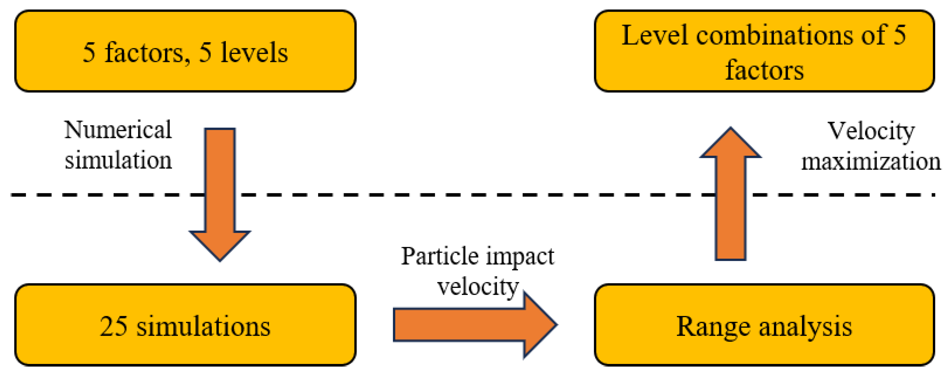
As shown in
Table 6, this orthogonal experiment employs a 5-factor, 5-level design, necessitating a total of 25 simulations. Using CATIA.composer.2024 software, 25 sets of three-dimensional nozzle models were created. The modeling process strictly followed the parameters specified in orthogonal experimental
Table 7 to ensure the accuracy of the experiments. Subsequently, Fluent 2020R1 software was used to compute each model group, analyzing internal gas flow dynamics and particle acceleration processes.
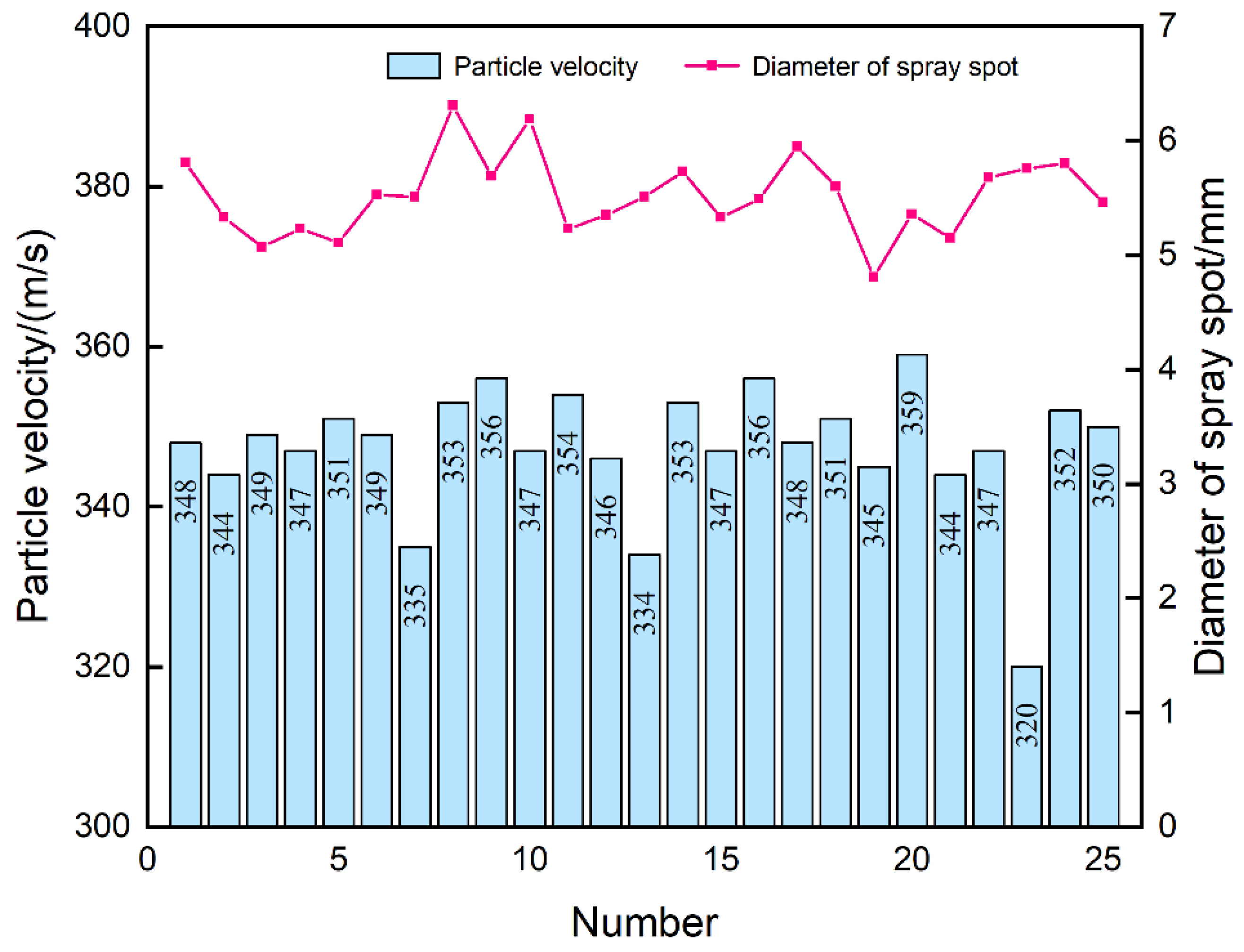
The results obtained from the simulation experiments are shown in
Figure 8. Using Minitab v21.2.0 software, the range analysis was conducted on the data obtained from the simulations specified in the orthogonal experimental table. In range analysis
Table 8,
i denotes the factor,
j denotes the level, and
represents the sum of all simulations corresponding to factor
i and level
j in all simulations, while
is the arithmetic mean.
represents the range, i.e., the difference between the maximum and minimum values of
.
The optimal experimental design within the tested range comprises combinations of levels for each factor that maximize particle impact velocity. Among the tested combinations, A4B5C4D5E2 (Inlet diameter 9 mm, throat diameter 5.6 mm, outlet diameter 6.2 mm, convergent length 50 mm, divergent length 5 mm) is identified as the optimal combination for maximizing particle impact velocity. Meanwhile, A larger range Ri indicates a greater influence of that factor on particle impact velocity. So, the order of influence on particle impact velocity is as follows: throat diameter > outlet diameter > inlet diameter > convergent length > divergent length. Finally, the range analysis was performed again based on the spray spot diameter, yielding Ri of less than 0.6 for all factors, indicating that the effect of the outer channel geometry on the spray spot diameter is small.
4.2. Effect of Air Pressure on Particle Velocity and Diameter of Spray Spot
Using orthogonal experimental design, the optimal parameter combination was determined through mathematical analysis. Based on this, the entrance pressure of the external channel was varied to investigate its effect on particle impact velocity and spray area diameter, as shown in
Table 9.
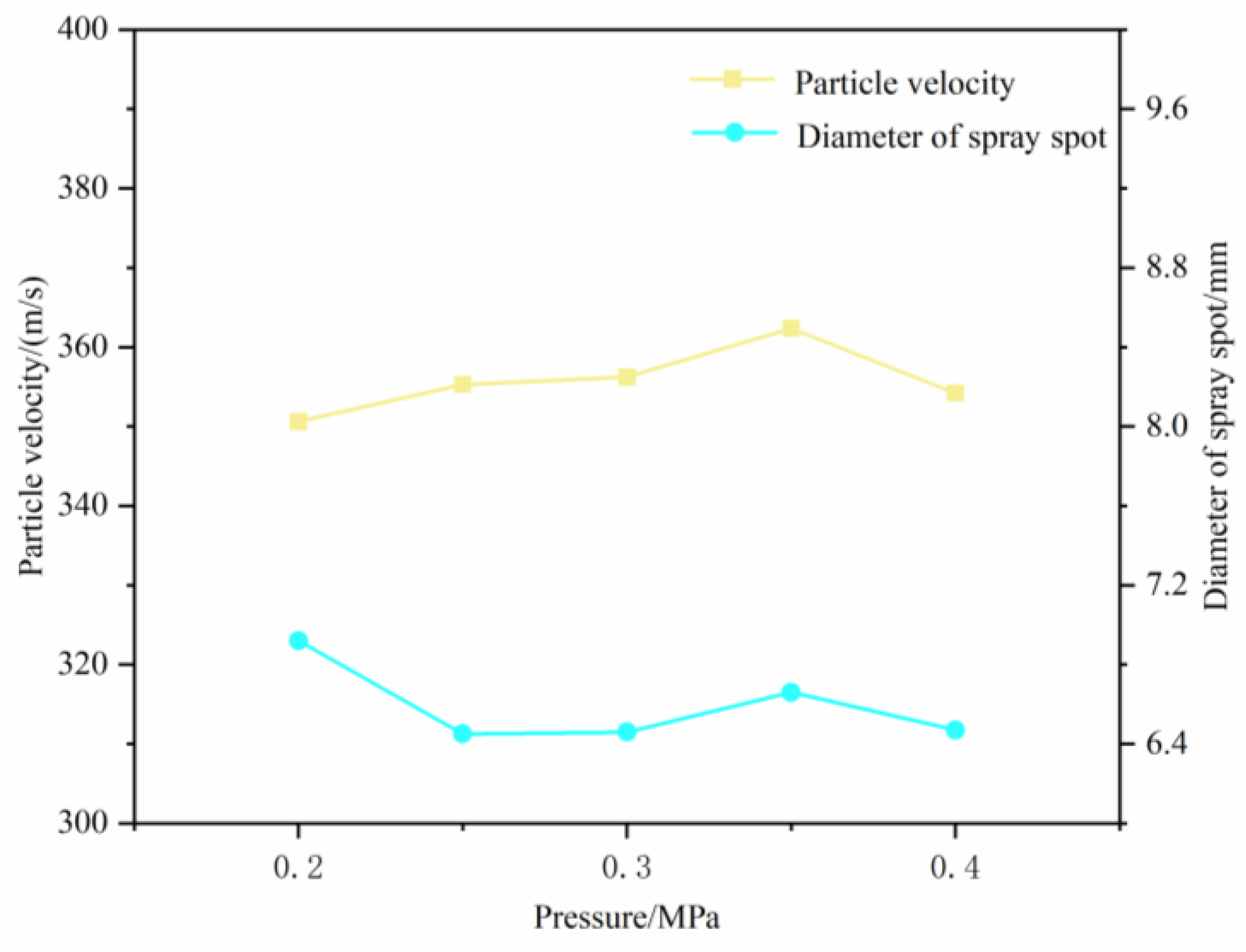
As shown in
Figure 9, while keeping other simulation conditions constant, varying the entrance pressure of the external channel results in changes in particle impact velocity and spray area diameter. From the graph, it is found that between 0.2 MPa and 0.35 MPa, there is an increasing trend of particle impact velocity with the increase of gas pressure. This indicates that increasing the gas pressure at the entrance of the external channel constrains the particles accelerated through the internal channel nozzle, thereby enhancing particle impact velocity, consequently improving deposition performance. However, this constraint has limited effect on particle divergence, and the particle impact velocity starts to decrease when the gas pressure exceeds 0.35 MPa. Furthermore, it is observed that when the gas pressure exceeds 0.4 MPa and reaches 0.45 MPa, there is a sharp decrease in particle impact velocity, with almost no particles exceeding the theoretical critical velocity. This suggests that beyond a certain pressure threshold at the external channel entrance, not only does particle impact velocity not increase, but it also affects the flow of gas within the internal channel, leading to spray failure. For the spray spot diameter, the gas pressure has little effect and the size is around 6.5 mm.
4.3. Comparison of CDB and Dual-Path Nozzle
According to the previous subsection, the optimized dual-path nozzle has the best spraying effect when the inlet pressure of the outer channel is 0.35 MPa. Therefore, the CDB nozzle and the optimized dual-path nozzle were compared under this spraying condition.
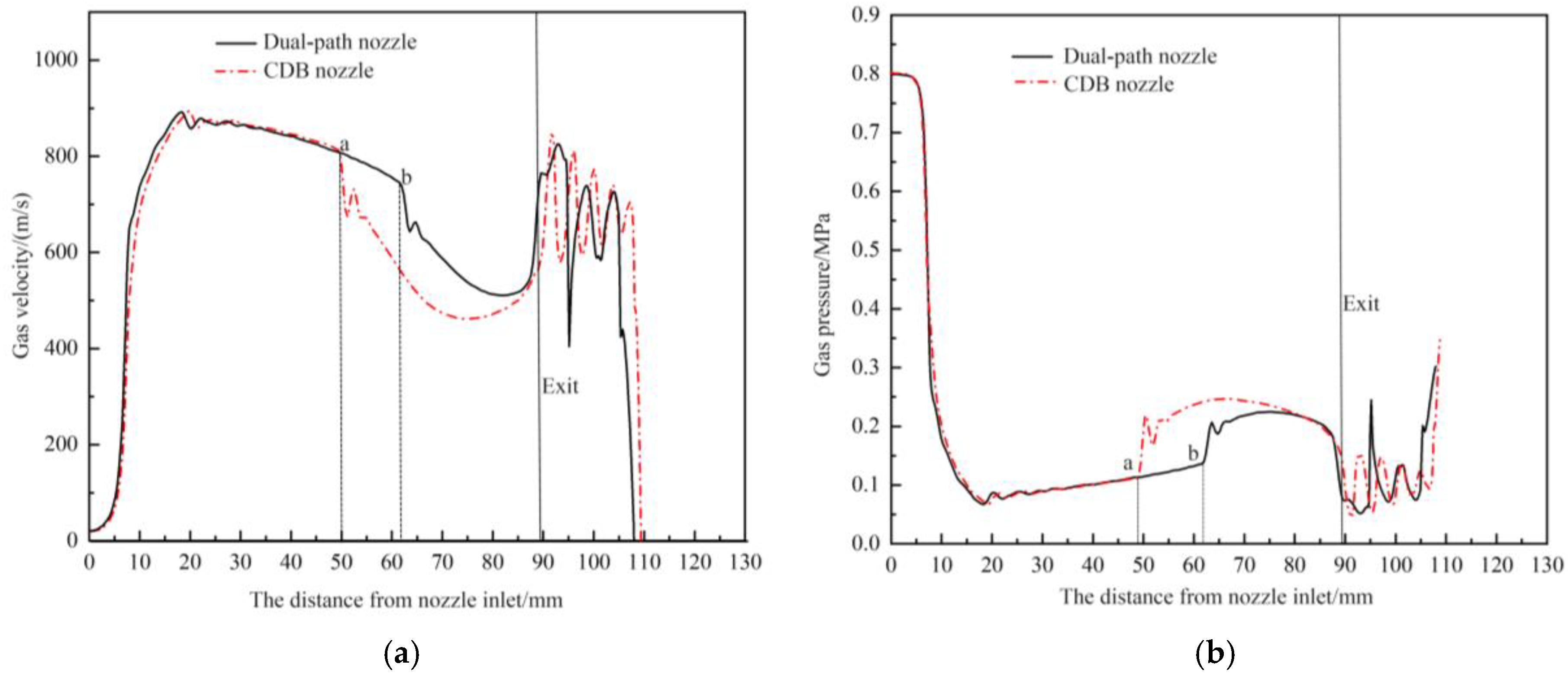
Figure 10 depicts the variation of gas pressure and velocity along the centerline of the CDB nozzle and the optimized dual-path nozzle. The solid black line represents the gas velocity and pressure variation inside the dual-path nozzle, while the dashed red line represents the variation within the inner channel. It can be observed from the figure that the trends of gas velocity and pressure along the centerline are generally similar for both nozzles. However, in the nozzle without an outer channel structure, gas velocity sharply decreases starting at point ‘a’ approximately 50 mm downstream from the nozzle inlet. This characteristic is typical of convergent-divergent-straight (CDS) supersonic nozzles, where gas, after the divergent section, enters a straight section with an unchanged cross-sectional area, leading to incomplete expansion due to friction with the nozzle walls, thereby causing a decrease in gas velocity. In contrast, in the dual-path nozzle, the sharp decrease in gas velocity occurs at point ‘b’ approximately 62 mm downstream from the nozzle inlet. Regarding the pressure variation, the gas pressure inside the nozzle without an outer channel structure increases earlier compared to the dual-path nozzle. This earlier pressure rise indicates a decrease in gas velocity as the gas undergoes pressure reduction and acceleration processes. This observation is consistent with the changes in gas velocity. It indicates that the outer channel structure can prolong the gas expansion distance, extend the pressure reduction and acceleration processes in the straight section, thereby enhancing the acceleration of particles within the straight section and increasing their impact velocity.
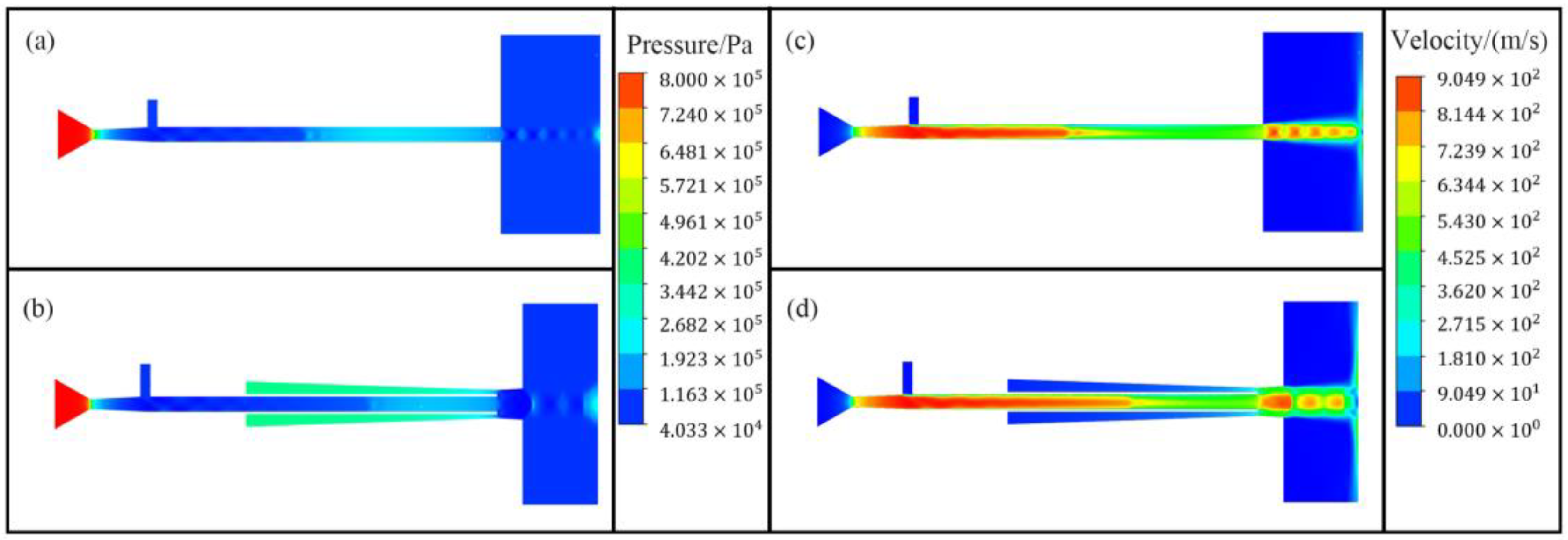
Figure 11 presents contour plots of gas velocity and pressure within both types of nozzles.
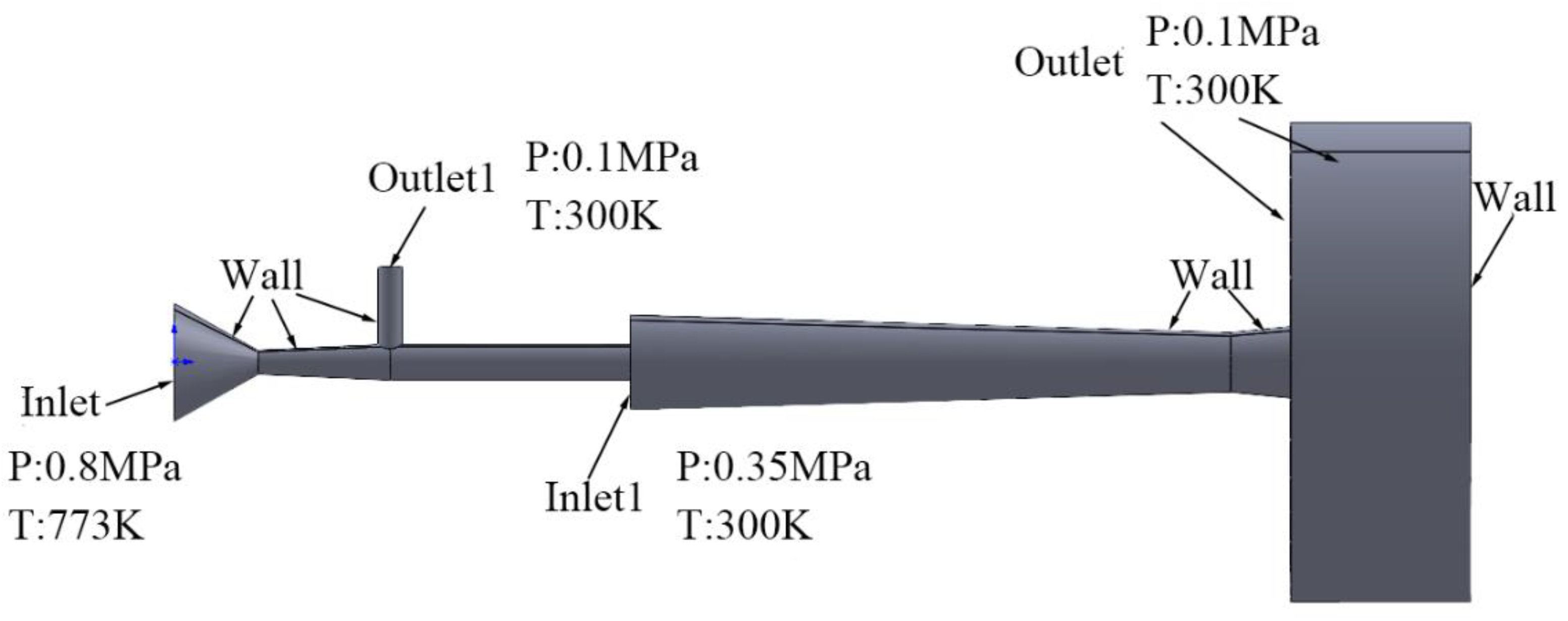
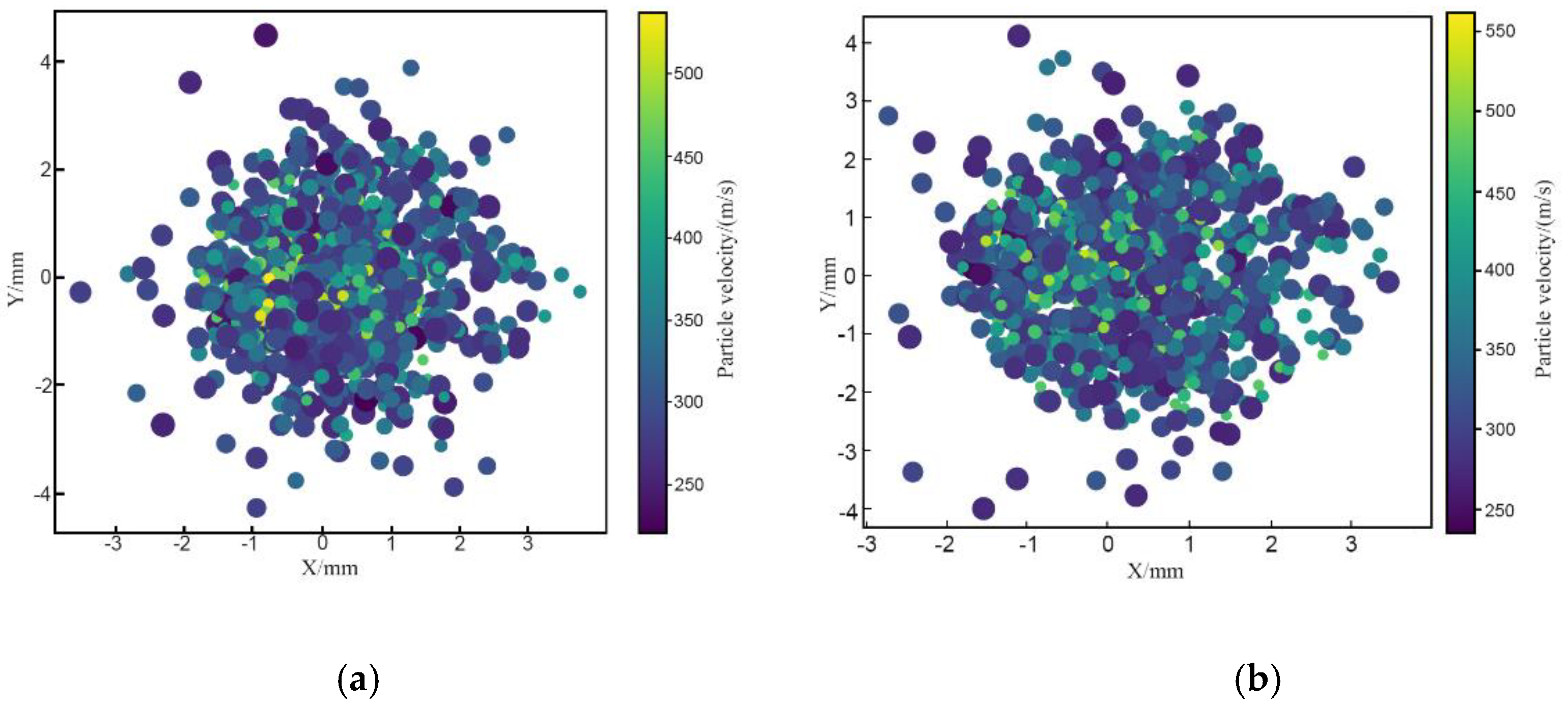
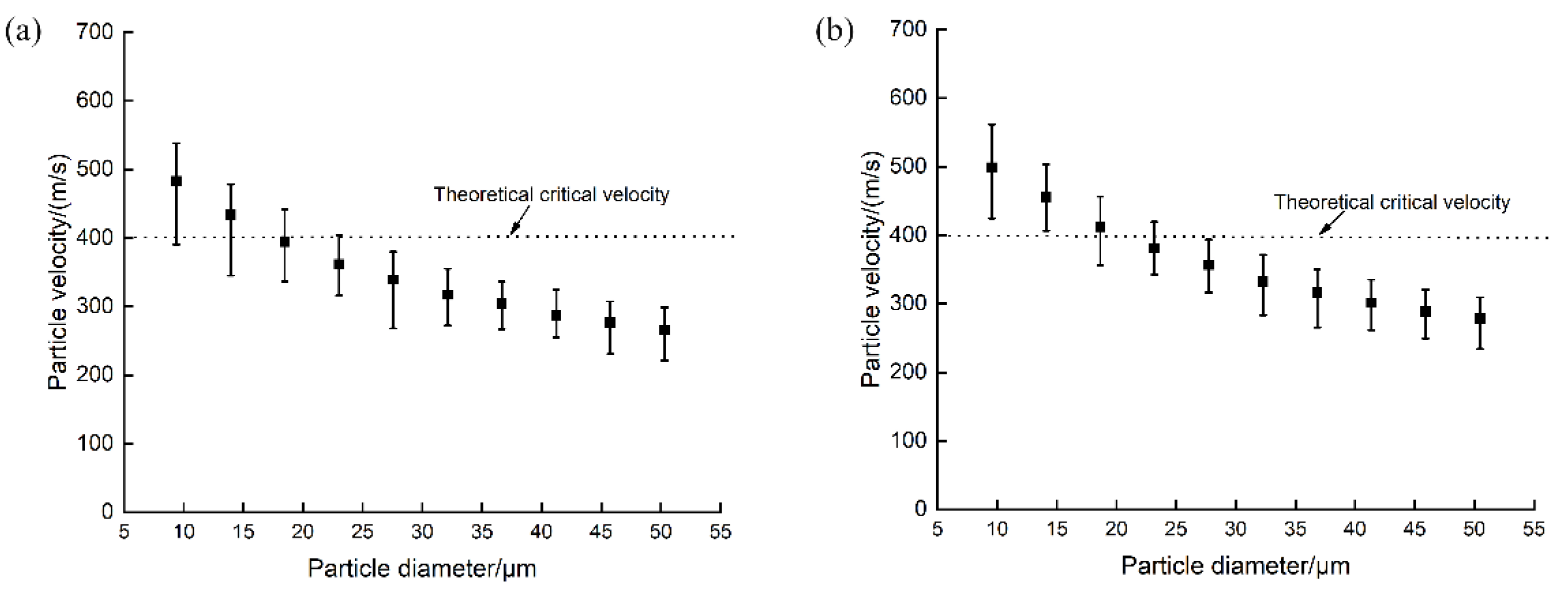
The theoretical critical velocity of aluminum particles under simulated conditions of 0.8 MPa and 773 K is approximately 400 m/s. The temperature is the particle temperature at impact.
Figure 12 displays the footprint distribution of all aluminum particles using CDB and dual-path nozzles under these conditions.
Figure 13 presents the distribution of impact velocities of all simulated particles from both nozzles, with particle diameters ranging from 10–50 μm. The total number of injected particles and the number of particles per diameter are consistent between simulations. From the figures, it is evident that particles accelerated by the dual-path nozzle exceed 400 m/s in greater numbers compared to those accelerated by the CDB nozzle. Particularly, aluminum particles with diameters less than 15 μm exceed the critical velocity. Additionally, for particles with a diameter of 25 μm, a significant majority accelerated by the dual-path nozzle have impact velocities below the theoretical critical velocity. In contrast, all particles accelerated by the CDB nozzle have impact velocities below the critical velocity, illustrating why the deposition efficiency of low-pressure cold spray is relatively low. Calculation of all particle data yields that the average impact velocity of particles using the dual-path nozzle is 363 m/s, which is 23 m/s higher than that achieved using the CDB nozzle without an outer channel structure. Furthermore, the number of particles exceeding the critical velocity increases by nearly 100, equating to an approximate 10% improvement in deposition efficiency. Considering particles exceeding the theoretical critical velocity as effectively deposition, the simulated spray diameter using the dual-path nozzle measures 6.69 mm, whereas that using the CDB nozzle measures 5.36 mm. In summary, a comparison of the simulation results of the CDB nozzle and the dual-path nozzle is shown in
Table 10, which indicates that using the dual-path nozzle enhances particle impact velocities and consequently improves deposition efficiency.
Figure 14 respectively show different deposits and their cross-sectional profiles obtained through cold spray experiments. Among them, Sample 1 uses a CDB nozzle, while Sample 2 uses a dual-path nozzle. It can be clearly seen from the figure that the deposition diameter obtained solely using the inner channel nozzle is approximately 5.7 mm, with a height of about 5.5 mm. In contrast, the deposition produced using the dual-path nozzle has a diameter of 7 mm and a height of 6.5 mm. These results indicate that using a nozzle with an outer channel structure enhances particle deposition efficiency, enabling more particles to reach critical velocity and deposit onto the substrate. Consequently, this results in depositions with larger diameters and greater heights.
As shown in
Table 11, the difference between the actual spray spot diameter obtained by using the dual-path nozzle and that obtained by numerical simulation is about 0.3 mm, which is a very small difference, further verifying the accuracy of the simulation model. At the same time, the spray spot diameter of the dual-path nozzle is larger than that of the CDB nozzle, which may be due to the increase in the kinetic energy of the impact of the particle beam, the particle inertia increases, and it is difficult for the airflow in the outer channel to effectively constrain the particle flow, which results in an increase in the spray spot diameter. However, the difference between the two is only about 1.3 mm, which can be explained to some extent that the main role of the outer channel is to increase the impact velocity of the particles, which has little effect on the spray spot diameter.
Three sets of replicated experiments were designed to reduce randomness. Each cold spray experiment was evaluated for particle deposition efficiency, and the results were recorded. Based on the collected data, deposition efficiencies for each group were calculated and are detailed in
Figure 15. Subsequently, the average deposition efficiencies of depositions produced using the two different nozzles were determined. By comparing the particle deposition efficiencies for the two nozzles, it can be observed that the average deposition efficiency using only the inner channel nozzle is approximately 20%, aligning with the characteristic low deposition efficiency of low-pressure cold spray and closely matching the simulated results, thereby validating the accuracy of the numerical simulation model. On the other hand, the actual average deposition efficiency of particles using the dual-path nozzle is approximately 28%, representing an improvement of about 8% over the nozzle without an outer channel structure. Correspondingly, the simulated deposition efficiency is 10%, indicating a close agreement between the actual and simulated results. This further confirms that the use of an outer channel structure enhances particle impact velocities, thereby improving particle deposition efficiency.
4.4. Evaluation of the Depositions
To investigate the influence of the optimized dual-path nozzle on the microstructure and mechanical properties of aluminum deposition, three groups of repeated experiments were designed under the condition that the inlet pressure of the outer pressure of the outer channel was 0.35 MPa to compare the optimized dual-path nozzle with the CDB nozzle.
Based on the data measured using Image-J V1.8.0 software, porosity values for three groups of depositions were determined, as detailed in
Figure 16. Comparing the data from the figure reveals that the porosity of depositions prepared using the inner channel nozzle is approximately 10.51%, whereas depositions prepared using the dual-path nozzle structure exhibit a porosity of about 9.12%. These results indicate that the dual-path nozzle enhances particle impact velocities. Higher impact velocities promote tighter particle bonding, thereby reducing deposition porosity. The study findings underscore that the porosity can be reduced by choosing an appropriate nozzle structure to a certain extent.
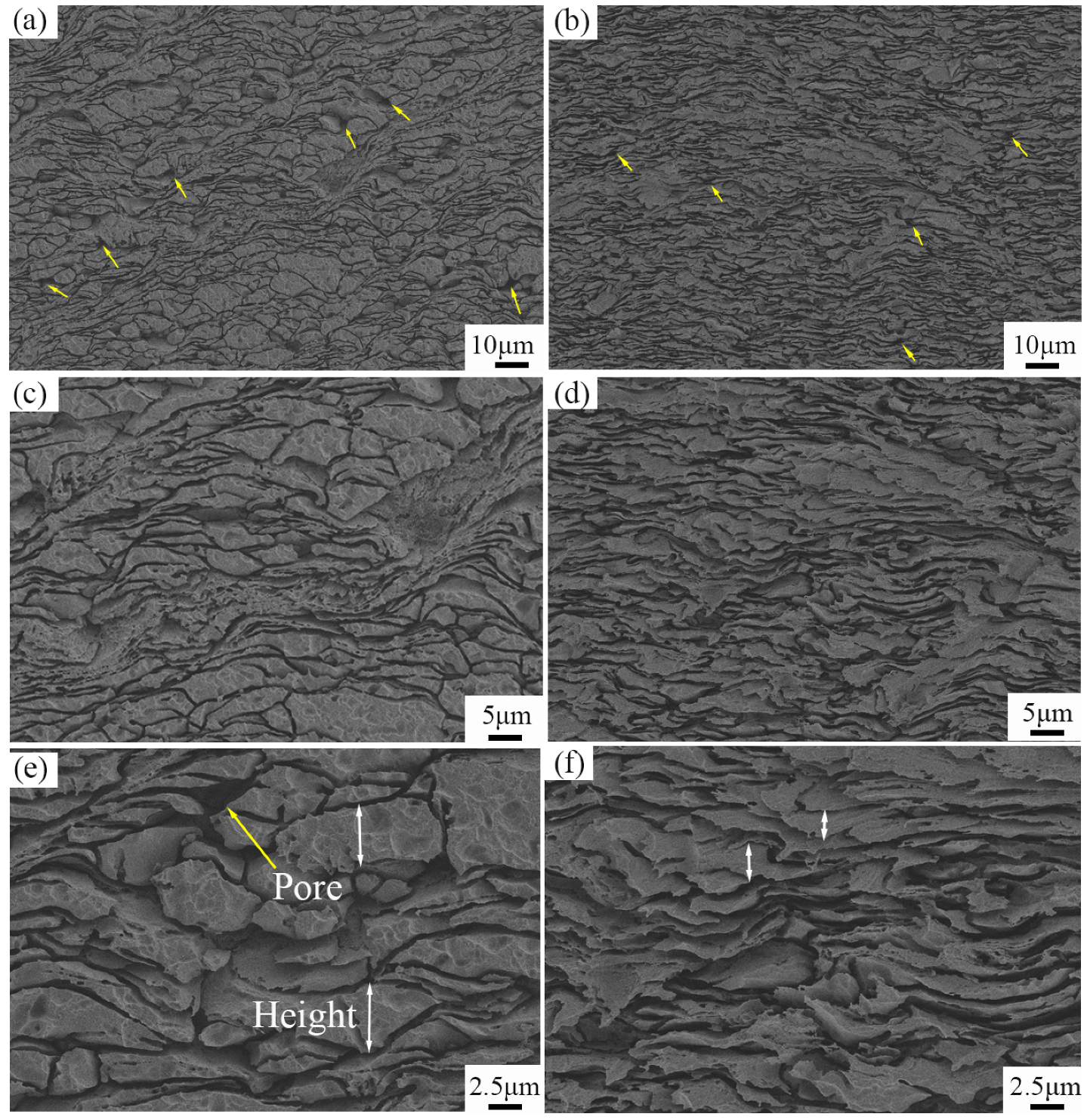
Figure 17 presents cross-sectional morphologies of depositions obtained via SEM. Panels (a), (c), and (e) depict microstructures of depositions produced using the inner channel nozzle at magnifications of 250×, 500×, and 1000× respectively, while panels (b), (d), and (f) depict microstructures of depositions produced using the dual-path nozzle at the same magnifications. In these images, yellow arrows indicate larger pores within the depositions, while white double arrows denote the height of aluminum particles deformed upon deposition onto the substrate. Observing
Figure 18, compared to high-pressure cold spraying, depositions produced by low-pressure cold spraying exhibit higher porosity with a greater number of larger pores, indicating poorer densification. Comparing the microstructures of depositions produced using the two different nozzle structures reveals that depositions from the dual-path nozzle exhibit fewer large pores on their cross-sections and tighter particle bonding. This observation stems from the higher flight velocities attained by particles within the dual-path nozzle, resulting in more effective particle compaction upon impact. Furthermore, increased particle impact velocities lead to greater particle deformation and increased particle-to-particle collisions, as evidenced by the significantly higher deformation height indicated by the white arrows in panel (f) compared to panel (e) of
Figure 17. Therefore, these results reaffirm that using a dual-path nozzle structure during cold spraying enhances particle impact velocities, thereby improving deposition performance. This improvement not only reduces deposition porosity but also enhances deposition densification.
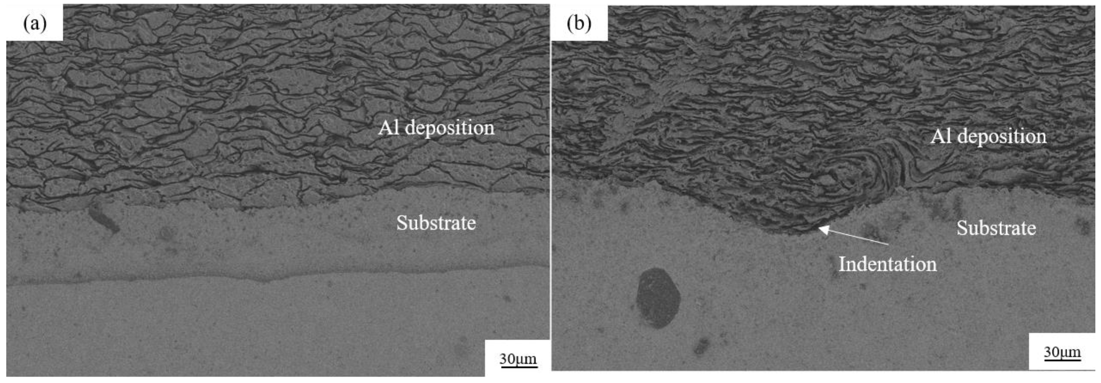
Figure 18 presents SEM micrographs at a magnification of 250, where panel (a) represents a deposition produced using the inner channel nozzle, and panel (b) represents a deposition produced using the dual-path nozzle. The micrographs reveal indentations at the interface between the deposition and the substrate, with depositions produced using the dual-path nozzle showing more pronounced indentations. This observation underscores the ability of the dual-path nozzle to impart higher particle impact velocities. However, it is important to note that these phenomena are influenced by thermal softening effects. At spraying temperatures reaching 500 °C, the substrate surface experiences preheating, which is a significant heat transfer mechanism. Moreover, the flight velocity of powder particles increases with spraying temperature, and upon impact with the substrate, the higher kinetic energy of particles is converted into thermal energy. As a result, thermal softening occurs on the substrate surface, facilitating cooperative deformation between powder particles and the substrate. This transformation from physical bonding to mechanical interlocking enhances the bond strength between powder particles and the substrate, further improving deposition adhesion.
The microhardness of three groups of depositions was measured; experimental results showed that the average microhardness of depositions produced using the inner channel nozzle is 33.4 ± 0.2 Hv, while those produced using the dual-path nozzle are 34.2 ± 0.2 Hv. The microhardness of depositions is primarily influenced by the deposition porosity and the extent of work hardening experienced after particle plastic deformation. Despite the slight difference in deposition hardness, there is still a discernible improvement. This is attributed to the higher velocity particles achieve within the dual-path nozzle, increasing the degree of deformation caused by particle-to-particle impacts and thereby reducing porosity. Significant plastic deformation increases the density of dislocations, leading to a slight increase in microhardness.


