Article

Effects of Compaction Thickness on Density, Integrity, and Microstructure of Green Parts in Binder Jetting Additive Manufacturing of Silicon Carbide

1
Department of Industrial & Systems Engineering, Texas A&M University, College Station, TX 77843, USA
2
Product Development, CPS Technologies Corp., Norton, MA 02766, USA
*
Author to whom correspondence should be addressed.
J. Manuf. Mater. Process. 2025, 9(4), 136; https://doi.org/10.3390/jmmp9040136
Submission received: 19 March 2025 / Revised: 13 April 2025 / Accepted: 17 April 2025 / Published: 19 April 2025

Abstract

:
Binder jetting additive manufacturing (BJAM) of silicon carbide (SiC) has been reported in the literature. In the reported studies, the effects of the compaction thickness on the properties of SiC green parts printed by BJAM have largely been unexamined. This study aims to fill this gap in the literature by investigating the effects of the compaction thickness on the density, integrity, and microstructure of SiC green parts printed by BJAM. In this study, experiments were conducted using four levels of compaction thickness at two levels of layer thickness. The results indicate that increasing the compaction thickness enhances the green part density, reaching 1.85 g/cm3 at a layer thickness of 45 µm and 1.87 g/cm3 at a layer thickness of 60 µm, respectively. However, a higher compaction thickness might also introduce defects in green parts, such as cracks. Scanning electron microscopy (SEM) analysis confirmed the improved particle packing and reduced porosity with the increased compaction thickness. These findings underscore a trade-off between density and defect formation, providing critical insights for optimizing BJAM process variables for fabricating SiC parts.

1. Introduction

Silicon carbide (SiC) has outstanding properties [1], including high mechanical strength, outstanding heat conductivity, chemical durability, and resistance to thermal shock [2]. These properties make SiC an essential material for demanding applications such as aviation, automotive engineering, and power generation, where the performance of components under extreme conditions is critical [3,4,5,6]. However, these properties also make it very difficult to fabricate SiC components using conventional manufacturing methods. Conventional methods such as hot pressing, sintering, and infiltration usually require high temperatures and significant energy inputs, often leading to long processing times and high production costs. Moreover, it is challenging to use these methods to produce SiC components with complex geometries without specialized tooling or extensive post-processing.
Binder jetting additive manufacturing (BJAM) can overcome these challenges. Unlike powder bed fusion (PBF), which requires a high energy input and results in high thermal stresses [7,8,9], BJAM operates at room temperature and can process a wide range of powder materials (metal, ceramics, composites) [10]. The quality (density and surface integrity) of green parts produced by BJAM is influenced by several variables (including layer thickness and compaction thickness). Here, green parts refer to printed parts formed by selectively binding powder particles with a liquid binding agent. These green parts generally need to go through post-printing steps (such as sintering) to become final parts. The layer thickness refers to the vertical height of each layer of powder that is spread across the build plate during the printing process [11]. The compaction thickness is an important process variable for BJ printers equipped with powder compaction capability. For each layer of deposited and spread powder, the initial total thickness of the layer is the sum of the layer thickness and compaction thickness. Before the liquid binder is ejected on the selected areas of the powder bed, a compaction roller presses this layer of powder and reduces the thickness of the layer to the final layer thickness. In other words, the compaction thickness represents the difference between the initial thickness of the deposited (and spread) powder layer and the final thickness of the powder layer after compaction [12].
Several studies have been reported using BJAM to fabricate SiC parts [3,12,13,14,15,16,17,18,19,20,21,22,23,24,25]. Table 1 shows some reported studies on green parts in BJAM.
In some reported studies on BJAM of ceramic materials, the effects of the compaction thickness were investigated [12,21,22]. Moghadasi et al. introduced a new approach by combining alumina nanopowder (with an average particle size of about 100 nm) with compaction in binder jetting to fabricate ceramic parts. While they varied the compaction thickness in their experiments, the primary objective of their study was to demonstrate the feasibility of this combined approach and not to systematically investigate the effects of the compaction thickness. Furthermore, their results were based on single experimental runs (without replications) and did not reveal variations in experimental data [21]. Du et al. examined the effects of the compaction thickness on zirconia (with an average particle size of 50 µm) green part density using one level of the layer thickness and four levels of the compaction thickness [22]. However, they did not analyze how the compaction thickness affected the microstructure of the green parts, leaving a gap in understanding the underlying mechanisms of densification. Pasha et al. conducted a full-factorial study with SiC powder (with an average particle size of 7 µm), incorporating two levels of the layer thickness and two levels of the compaction thickness to assess their effects on green part density [12]. However, the main focus of their study was to assess the interaction effect between these variables rather than to explore the detailed effects of the compaction thickness alone. Additionally, their work did not examine the resulting defects of the green parts, leaving gaps in understanding the mechanisms behind densification and defect formation. This study aims to bridge these gaps by experimentally evaluating the effects of the compaction thickness at multiple levels on the density, structural integrity, and microstructure of SiC green parts printed by BJAM.
In this study, the density was measured on green parts printed by BJAM at four levels of the compaction thickness (and at two levels of the layer thickness). This paper starts with an introduction, followed by Section 2, which outlines the materials and methods utilized in this research. Section 3 shows the effects of the compaction thickness on the density, structural integrity, and microstructure of green parts. Finally, Section 4 summarizes the key conclusions derived from the study.

2. Experimental Method

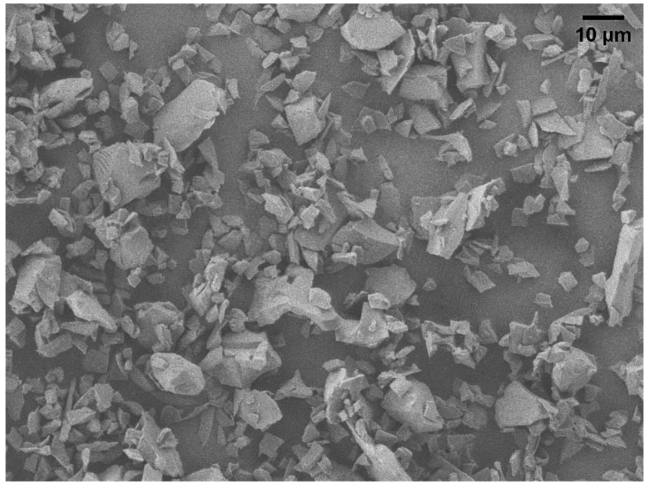
2.1. Feedstock Powder

The SiC powder utilized in this study was provided by Electro Abrasives LLC, Buffalo, NY, USA. Upon receipt, its particle size distribution (PSD) was analyzed using a laser scattering particle size analyzer (Horiba LA-960, Kyoto, Japan). The particle size distribution was characterized by D10, D50, and D90 values of 6 μm, 14 μm, and 70 μm, respectively. D10, D50, and D90 correspond to the particle sizes at which 10%, 50%, and 90% of the total volume distribution falls below the respective values. The true density of the powder, measured using a gas pycnometer (Micromeritics, AccuPyc II 1345, Norcross, GA, USA), was 3.21 g/cm3. The true density of a powder refers to the density of the solid material itself, excluding any void spaces or pores between individual particles [26]. A scanning electron microscope (SEM: JSM7500, RRID: SCR_022202, JEOL, Tokyo, Japan) was used to examine the as-received SiC powder. Figure 1 shows an SEM image of the SiC powder. It can be observed that most of the powder particles had irregular shapes.

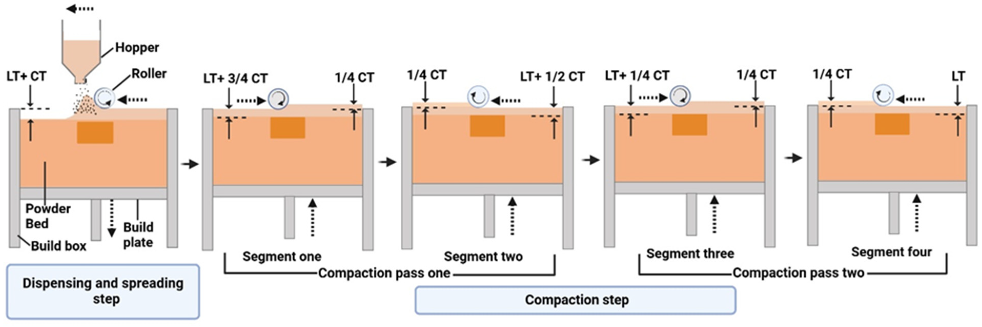
2.2. Binder Jetting of Green Parts

Computer-aided design (CAD) software, Creo Parametric v9.0 (Boston, MA, USA), was employed to develop the 3D model of the printed components, which measured 22 mm in length, 20 mm in width, and 3.5 mm in thickness. The same software was utilized to generate the corresponding STL file, which was subsequently converted into G-code to provide precise instructions for the printer’s operation.
The printing procedure followed in this study was the same as that detailed in a previous paper [12]. A binder jetting system (Innovent+, ExOne Company, North Huntington, PA, USA) was used in conjunction with an aqueous binder (BA005, ExOne Company, North Huntington, PA, USA). Detailed printing steps are described in previous publications [12,21].
Figure 2 illustrates two steps for binder jetting printing of green parts using powder bed compaction. In the dispensing and spreading step, the powder is dispensed from the hopper to the powder bed as the hopper moves across the build plate. At the same time, a counter-rotating roller spreads the dispensed powder from right to left, filling the space between the build plate and the roller. The total deposited powder thickness corresponds to the sum of the layer thickness (LT) and compaction thickness (CT). In the compaction step, the build plate is raised by a distance equal to the compaction thickness, and the roller compresses the spread powder, reducing the total thickness (LT + CT) to the final layer thickness (LT). This compaction step may involve multiple passes depending on the designated number of compaction cycles. In this study, two compaction passes were performed, with each pass comprising two segments—one from right to left and the other from left to right—resulting in a total of four segments. During each segment, the build plate was raised incrementally by one-fourth of the compaction thickness (CT/4), while the roller, rotating forward, compacted the powder bed [27].
Table 2 presents the fixed values of the printing variables. The definitions of these variables can be found in the literature [19]. Preliminary trials were conducted to establish each value, focusing on achieving good powder bed quality (e.g., minimal surface defects) and ensuring that the green parts met the necessary strength requirements.
In each experimental run, eight green parts were printed. They were arranged on the XY plane (as shown in Figure 3), with the thickness oriented along the build (Z) direction. The parts were labeled to denote their positions on the build plate: “T1” and “T2” for the top zone, “M1”, “M2”, “M3”, and “M4” for the middle zone, and “B1” and “B2” for the bottom zone, as illustrated in Figure 3. In the figure, the X-direction (also known as the spread direction) is the direction in which the roller spreads the dispensed powder from right to left during the dispensing and spreading step.
After printing, the build box, which contained both the printed green parts and loose powder, was placed in an oven (DX402C, Yamato Scientific, Tokyo, Japan) for 5 h at 125 °C to cure the binder in the green parts. This curing process was intended to improve the mechanical strength of the green parts in preparation for the subsequent depowdering step [12].

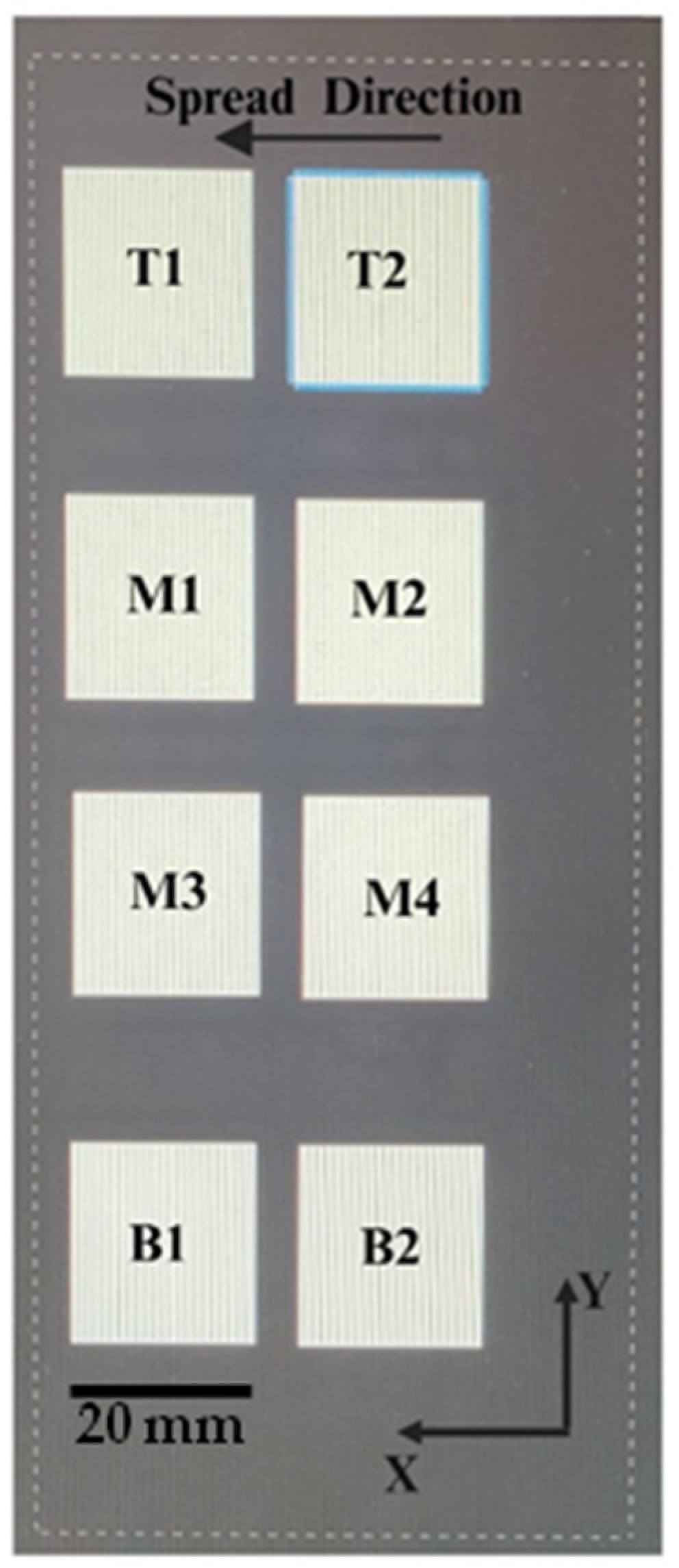
2.3. Design of Experiments

Two levels of the layer thickness, 45 and 60 µm, were selected. For each level of the layer thickness, four levels of the compaction thickness were applied: 25, 35, 45, and 55 µm for a layer thickness of 45 µm, and 40, 50, 60, and 70 µm for a layer thickness of 60 µm. In each experimental condition listed in Table 3, eight green parts were printed. Two replications were made for each experimental condition.

2.4. Measurement of Density of Green Parts

The green density ( ρ ) of the printed parts was determined based on geometric and mass measurements. Geometric measurements (length, width, and thickness) of the green parts were obtained using a slide caliper (500-196-30 Digimatic 0–6″/150 MM stainless steel digital caliper, Mitutoyo, Japan). Mass measurements were taken with a scale that had a resolution of 0.001 g. Using Equation (1), the green part density was calculated, with m representing the mass of the part and l, w, and t denoting the length, width, and thickness of the green part, respectively.
G r e e n   p a r t   d e n s i t y   ( ρ ) = m / ( l w t )

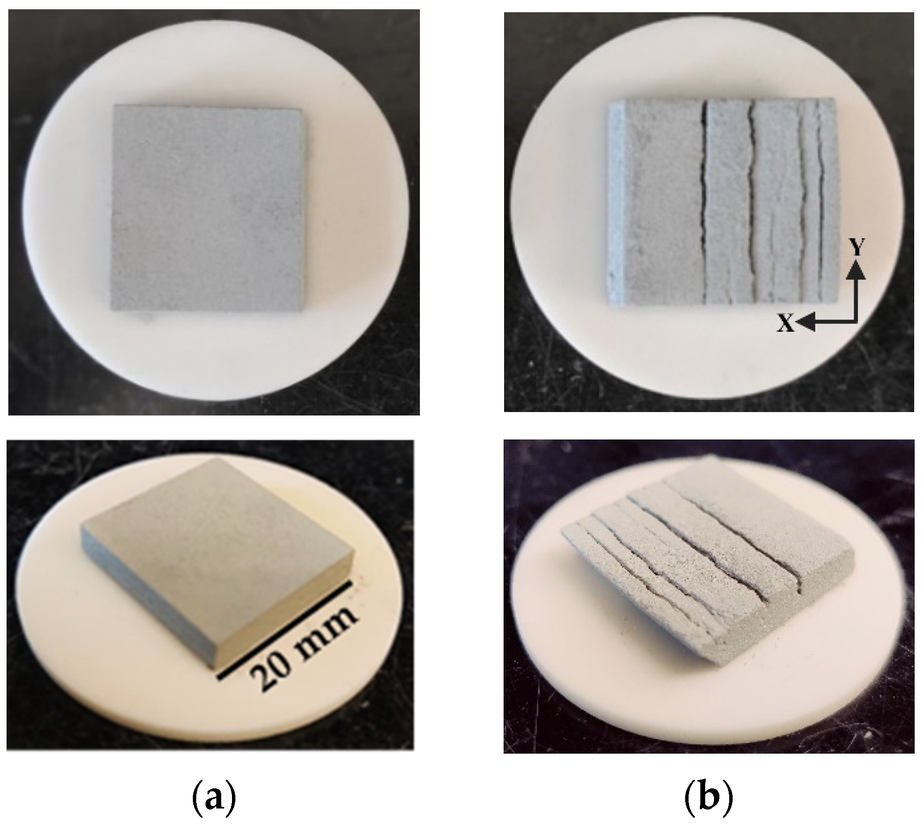
2.5. Evaluation of Integrity of Green Parts

The integrity of the printed green parts was evaluated through visual inspection. Each green part was visually inspected. When a green part had no crack, as shown in Figure 4a, it was considered a good sample. In contrast, when a green part had at least one crack, as shown in Figure 4b, it was considered a defective sample.

2.6. Characterization of Microstructure of Green Parts

The microstructure of the green parts was characterized by manually breaking them along the bend line, as illustrated in Figure 5, using hand pressure. To prepare the fractured surfaces for SEM imaging, a 5 nm platinum (Pt) coating was applied using a Sputter Coater (Cressington 208HRD High-Resolution, Watford, UK) to enhance the conductivity and improve the image quality. After cleaning and drying, the sample was placed into the sputter coater. The sputter coater and thickness monitor were turned on, and the coating thickness was set to 5 nm on the thickness monitor. After the chamber reached full vacuum, the coating process began and automatically stopped once the desired thickness was reached. After waiting for 30 s, the sample was carefully removed from the sputter coater and used for imaging in the SEM (JSM7500, RRID: SCR_022202, JEOL, Tokyo, Japan). SEM images of the fractured surfaces were captured with a magnification of 2000×.

3. Results and Discussion

3.1. Results

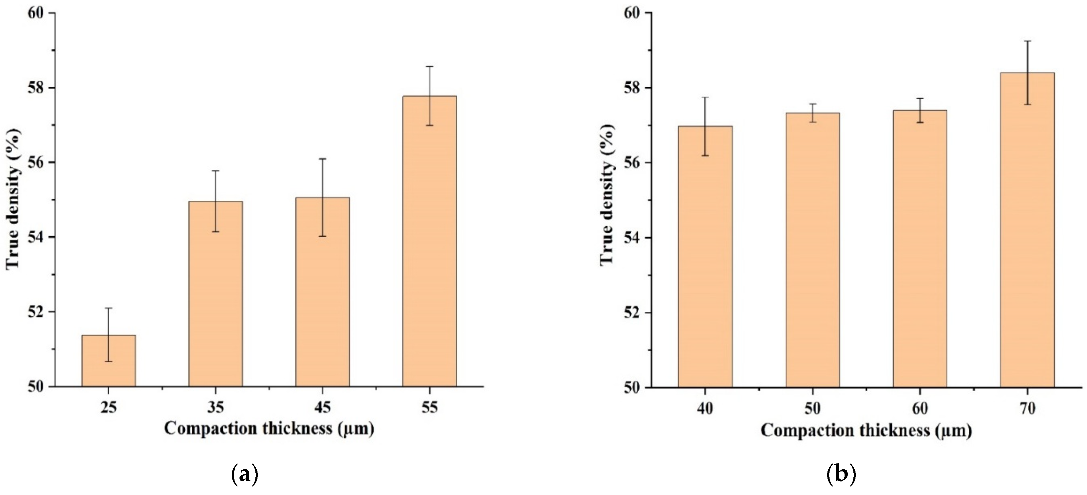
3.1.1. Effects of Compaction Thickness on Density of Green Parts

The location of a printed green part on the build plate influences its density, and significant variations in density can occur among printed parts within the same experimental run on the printer used in this study [12,28]. Including multiple parts in a single run could result in excessive variation in the collected density data. To eliminate this potential confounding factor, only one part from each experiment run was included in the data analysis, with the part located at position M3 for a layer thickness of 45 µm and B2 for a layer thickness of 60 µm, as shown in Figure 3. Two different locations were selected because the locations of good green parts were not the same when layer thickness was different. For a layer thickness of 45 µm, good green parts were at location M3 at all levels of the compaction thickness, while for a layer thickness of 60 µm, they were at location B2.
Table 4 shows experimental data for green part density. The green part density percentage was calculated from the measured density of the green part and the true density of the SiC powder using Equation (2).
G r e e n   p a r t   d e n s i t y   % =   M e a s u r e d   g r e e n   p a r t   d e n s i t y T r u e   d e n s i t y   o f   S i C   p o w d e r 100
Figure 6 shows the effects of the compaction thickness on the green part density at two levels of the layer thickness. The error bars are the standard deviation across two replications. It can be seen that as the compaction thickness increased, the green part density improved.

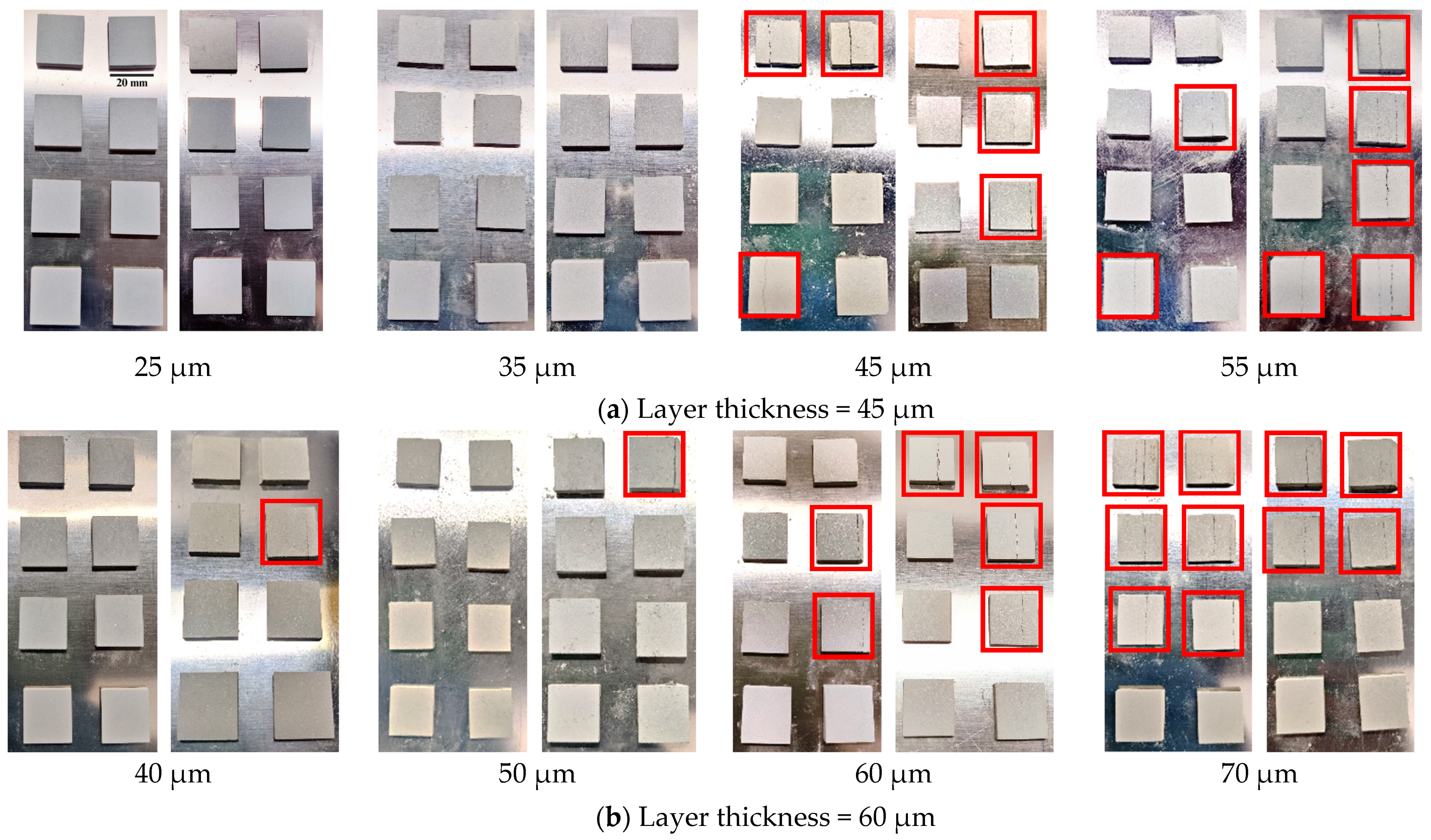
3.1.2. Effects of Compaction Thickness on Integrity of Green Parts

Figure 7 shows the effects of the compaction thickness on the integrity of the green parts for two different layer thickness. Across both Figure 7a,b, a consistent trend can be observed: as the compaction thickness increased, the integrity of the green parts decreased.

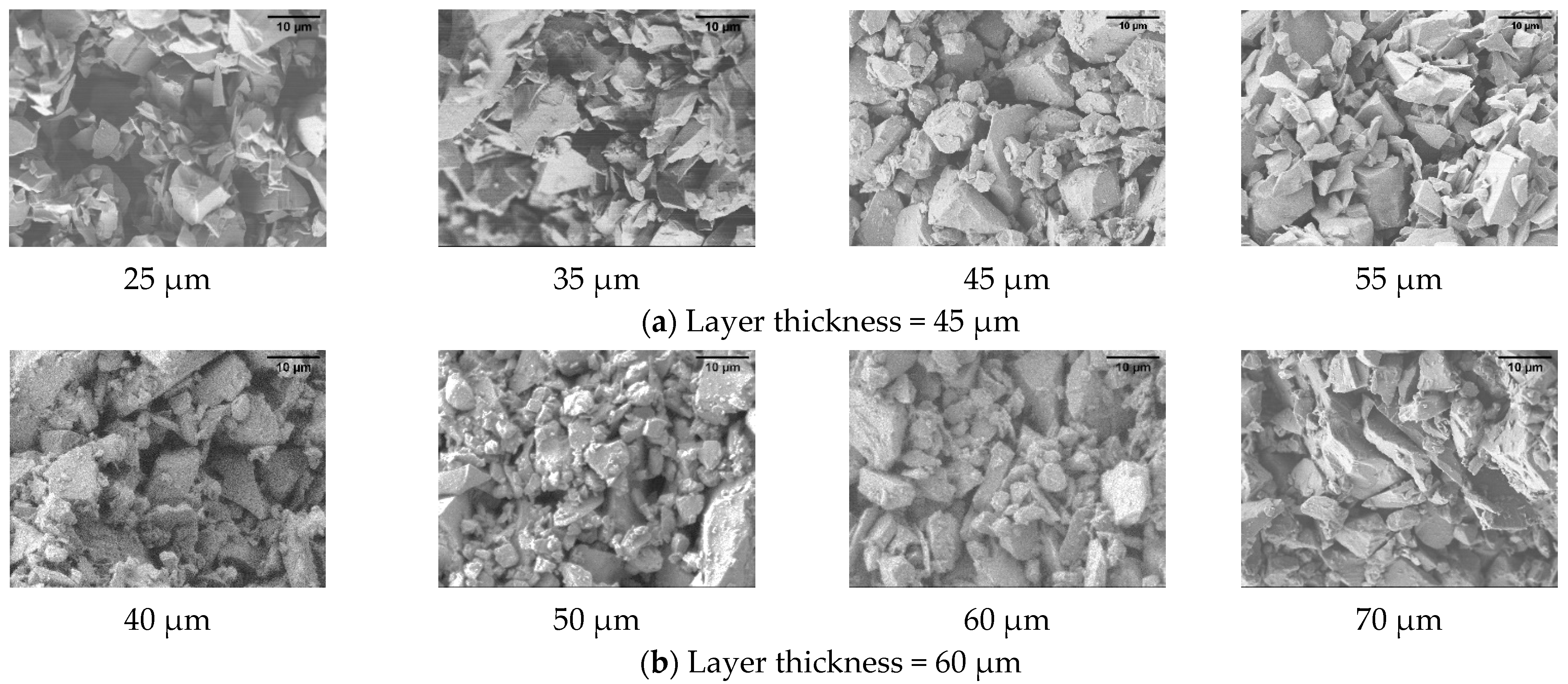
3.1.3. Effects of Compaction Thickness on Microstructure of Green Parts

Figure 8 shows the effects of the compaction thickness on the microstructure of the green parts for two different layer thicknesses, highlighting consistent trends in particle packing and porosity.

3.2. Discussion

The SiC powder used in this study had a wide particle size distribution (D10 = 6 µm, D50 = 14 µm, and D90 = 70 µm), and its particle shape appeared irregular. In comparison, the powders used in other binder jetting studies (summarized in Table 1) had relatively narrow particle size distributions [12,22], smaller particle sizes (nano-scale alumina [21]), and more spherical particle shapes (many metal powders such as stainless steel or WC-Co [13,18,19].
The experimental results show that increasing the compaction thickness enhanced the green part density, a trend that aligns with findings from previous studies on binder jetting using compaction (with different types or/and sizes of powder) [12,21,22]. For instance, Moghadasi et al. used alumina nano-powder with an approximate particle size of 100 nm. They observed a 2.5% increase in green part density when the compaction thickness was increased from 0 to 200 µm at a layer thickness of 30 µm [21]. Du et al. employed zirconia powder (with an average particle size of 50 µm) and found a 6% increase in green part density when the compaction thickness was raised from 0 to 200 µm at a layer thickness of 120 µm [22]. Pasha et al. used SiC powder with an average particle size of 7 µm and reported a 2% increase in green part density when the compaction thickness was increased from 30 to 60 µm at a layer thickness of 60 µm and less than a 1% increase in green part density when the compaction thickness was increased from 30 to 60 µm at a layer thickness of 90 µm [12].
As shown in Figure 6, the error bars for the layer thickness of 45 µm were consistently higher across all the compaction thickness levels compared with those at a layer thickness of 60 µm. This increased variation may result from the limited ability of the powder particles to rearrange themselves during spreading and compaction, given the wide particle size distribution (D10 = 6 µm, D50 = 14 µm, D90 = 70 µm).
While an increased compaction thickness improved the density, it reduced the green part integrity, as observed in Figure 7. For a layer thickness of 45 µm, as shown in Figure 7a, lower levels of the compaction thickness resulted in green parts with high integrity and minimal or no visible defects. However, as the compaction thickness increased, defects (such as visible cracks) emerged, and the overall integrity deteriorated, with the highest compaction thickness leading to the worst integrity. Similarly, as shown in Figure 7b, for a layer thickness of 60 µm, the green parts maintained high integrity at lower levels of the compaction thickness, but as the compaction thickness increased, cracks became more prominent, and the integrity significantly decreased. The highest level of the compaction thickness resulted in the most severe defects, with larger and more cracks. It can also be observed in Figure 7 that the green parts printed on the right side of the build plate exhibited more visible cracks compared with those printed on the left side, regardless of the compaction thickness level. Further investigation is needed to evaluate the packing density of the powder bed, both at the beginning and end of the spreading process after dispensing. Additionally, examining how the packing density varies with each layer of the green parts could provide valuable insights into the causes of such location-wise density variation in the green parts. The trend of increasing the compaction thickness leading to improved density is further supported by the microstructural analysis shown in Figure 8. As shown in Figure 8a,b, lower levels of the compaction thickness resulted in loosely packed particles with visible inter-particle gaps, indicative of higher porosity. As the compaction thickness increased, the particles became more closely packed, leading to a gradual reduction in porosity. At the highest compaction thickness level, the particle arrangement was densest, with minimal inter-particle gaps, reflecting improved packing and reduced porosity.
The experimental findings highlight the critical role of the compaction thickness in the binder jetting process. The compaction thickness should be optimized with consideration of both green part density and structural integrity. While higher levels of the compaction thickness can reduce porosity and generally improve green part density, they tend to introduce defects in the green parts.

4. Conclusions

In this study, the effects of the compaction thickness on the density, integrity, and microstructure of silicon carbide (SiC) green parts printed by binder jetting additive manufacturing (BJAM) were evaluated. As the compaction thickness increased, the green part density increased, reaching 1.85 g/cm3 at a layer thickness of 45 µm and 1.87 g/cm3 at a layer thickness of 60 µm, respectively. However, these higher levels of the compaction thickness introduced defects such as cracks in the printed green parts, indicating a trade-off between density and structural integrity. SEM imaging supported this trend, showing denser particle packing and reduced porosity with an increased compaction thickness.
These results contribute to a deeper understanding of the complex relationship between process variables and the quality of green parts in BJAM. Optimizing the compaction thickness is essential not only for improving the green part density but also for structural integrity and minimizing defects. Future research should explore the effects of the binder saturation on the green part density, as it is another key variable in BJAM. Future research studies should also include measuring the mechanical properties (e.g., flexural strength, hardness) of green parts. Additionally, the mechanisms that contribute to density enhancement and crack formation are not fully understood. The authors plan to investigate the effects of the powder morphology, including particle size and distribution, as well as particle shape, on powder densification and defect formation in BJAM. Advancing this knowledge is crucial for developing high-performance ceramic components through binder jetting technology.

Author Contributions

Conceptualization, M.M.P. and Z.P.; methodology, M.M.P. and Z.P.; formal analysis, M.M.P.; experiment, M.M.P. and M.S.A.; resources, Z.P. and S.K.; data curation, M.M.P. and Z.P.; writing—original draft preparation, M.M.P.; writing—review and editing, Z.P., M.M.P., M.S.A., F.K., J.S., and S.K. All authors have read and agreed to the published version of the manuscript.

Funding

This research received no external funding.

Data Availability Statement

The original data in this study are included in the article. Further inquiries can be directed to the corresponding author.

Acknowledgments

The authors would like to acknowledge that the characterization part of this work was performed at the Texas A&M University Materials Characterization Core Facility (RRID: SCR_022202). The authors extend their special thanks to Yordanos Bisrat for assistance with scanning electron microscopy (SEM). Furthermore, the authors would like to acknowledge Taieba Tuba Rahman (graduate student, Department of Industrial & Systems Engineering, Texas A&M University, College Station, TX 77843, USA) for her help in preparing the illustrations for this paper. Moreover, the authors thank Alex Castillo (undergraduate student, Department of Manufacturing and Mechanical Engineering Technology, Texas A&M University, College Station, TX 77843, USA), Steven Kuntzendorf, and Drew Dalabakis (undergraduate student, Department of Industrial & Systems Engineering, Texas A&M University, College Station, TX 77843, USA) for their assistance in the experiment conducted in this paper.

Conflicts of Interest

Authors Mostafa Meraj Pasha, Md Shakil Arman, Fahim Khan, Jackson Sanders, and Zhijian Pei are employed by Texas A&M University, College Station, and Stephen Kachur is employed by the company CPS Technologies Corp. The remaining authors declare that the research was conducted in the absence of any commercial or financial relationships that could be construed as a potential conflict of interest.

References

  1. Boretti, A.; Castelletto, S. A perspective on 3D printing of silicon carbide. J. Eur. Ceram. Soc. 2024, 44, 1351–1360. [Google Scholar] [CrossRef]
  2. Eom, J.-H.; Kim, Y.-W.; Raju, S. Processing and properties of macroporous silicon carbide ceramics: A review. J. Asian Ceram. Soc. 2013, 1, 220–242. [Google Scholar] [CrossRef]
  3. Polozov, I.; Razumov, N.; Masaylo, D.; Silin, A.; Lebedeva, Y.; Popovich, A. Fabrication of silicon carbide fiber-reinforced silicon carbide matrix composites using binder jetting additive manufacturing from irregularly-shaped and spherical powders. Materials 2020, 13, 1766. [Google Scholar] [CrossRef]
  4. Steibel, J. Ceramic matrix composites taking flight at GE Aviation. Am. Ceram. Soc. Bull 2019, 98, 30–33. [Google Scholar]
  5. Zhu, D. Aerospace Ceramic Materials: Thermal, Environmental Barrier Coatings and SiC/SiC Ceramic Matrix Composites for Turbine Engine Applications; Glenn Research Center: Brook Park, OH, USA, 2018. [Google Scholar]
  6. Wang, X.; Gao, X.; Zhang, Z.; Cheng, L.; Ma, H.; Yang, W. Advances in modifications and high-temperature applications of silicon carbide ceramic matrix composites in aerospace: A focused review. J. Eur. Ceram. Soc. 2021, 41, 4671–4688. [Google Scholar] [CrossRef]
  7. Chatterjee, S.; Cholkar, A.; Kinahan, D.; Brabazon, D. Fabrication of Periodic Textures at Micron Level on Silicone Membrane Using Femtosecond Laser. In Proceedings of the TMS Annual Meeting & Exhibition, Orlando, FL, USA, 3–7 March 2024; pp. 1551–1562. [Google Scholar]
  8. Mahato, V.; Chatterjee, S.; Nyabadza, A.; Caputo, A.; Brabazon, D. Layer porosity in powder-bed fusion prediction using regression machine learning models and time-series features. Int. J. AI Mater. Des. 2024, 1, 33–49. [Google Scholar] [CrossRef]
  9. Banerjee, A.; Mondal, A.K.; Haldar, B.; Chatterje, S.; Alsaleh, N.A. Synthesis and characterisation of Fe38Al26Cu16Ni13Cr6 high entropy alloy processed through combined cable wire arc additive manufacturing (WAAM) process. Int. J. Adv. Manuf. Technol. 2024, 135, 5553–5573. [Google Scholar] [CrossRef]
  10. Khan, F.; Arman, M.S.; Sanders, J.; Pasha, M.M.; Rahman, A.M.; Pei, Z.; Dong, T. Binder Jetting 3D Printing Utilizing Waste Algae Powder: A Feasibility Study. Intell. Sustain. Manuf. 2024, 1, 10016. [Google Scholar] [CrossRef]
  11. Mostafaei, A.; Elliott, A.M.; Barnes, J.E.; Li, F.; Tan, W.; Cramer, C.L.; Nandwana, P.; Chmielus, M. Binder jet 3D printing—Process parameters, materials, properties, modeling, and challenges. Prog. Mater. Sci. 2021, 119, 100707. [Google Scholar] [CrossRef]
  12. Pasha, M.M.; Arman, M.S.; Khan, F.; Pei, Z.; Kachur, S. Effects of Layer Thickness and Compaction Thickness on Green Part Density in Binder Jetting Additive Manufacturing of Silicon Carbide: Designed Experiments. J. Manuf. Mater. Process. 2024, 8, 148. [Google Scholar] [CrossRef]
  13. Enneti, R.K.; Prough, K.C. Effect of binder saturation and powder layer thickness on the green strength of the binder jet 3D printing (BJ3DP) WC-12% Co powders. Int. J. Refract. Met. Hard Mater. 2019, 84, 104991. [Google Scholar] [CrossRef]
  14. Pasha, M.M.; Pei, Z.; Arman, M.S.; Gasdaska, C.J.; Kao, Y.-T. Effects of Mixing Speed and Mixing Time on Powder Segregation During Powder Mixing for Binder Jetting Additive Manufacturing: An Experimental Study. J. Manuf. Mater. Process. 2025, 9, 117. [Google Scholar] [CrossRef]
  15. Khan, F.; Sanders, J.; Arman, M.S.; Pasha, M.M.; Kachur, S.; Pei, Z. Fabrication of SiC–Aluminum Composites via Binder Jetting 3D Printing and Infiltration: A Feasibility Study. J. Compos. Sci. 2025, 9, 111. [Google Scholar] [CrossRef]
  16. Miyanaji, H.; Rahman, K.M.; Da, M.; Williams, C.B. Effect of fine powder particles on quality of binder jetting parts. Addit. Manuf. 2020, 36, 101587. [Google Scholar] [CrossRef]
  17. Jimenez, E.M.; Ding, D.; Su, L.; Joshi, A.R.; Singh, A.; Reeja-Jayan, B.; Beuth, J. Parametric analysis to quantify process input influence on the printed densities of binder jetted alumina ceramics. Addit. Manuf. 2019, 30, 100864. [Google Scholar] [CrossRef]
  18. Chen, W.; Chen, Z.; Chen, L.; Zhu, D.; Fu, Z. Optimization of printing parameters to achieve high-density 316L stainless steel manufactured by binder jet 3D printing. J. Mater. Eng. Perform. 2023, 32, 3602–3616. [Google Scholar] [CrossRef]
  19. Mostafaei, A.; De Vecchis, P.R.; Kimes, K.A.; Elhassid, D.; Chmielus, M. Effect of binder saturation and drying time on microstructure and resulting properties of sinter-HIP binder-jet 3D-printed WC-Co composites. Addit. Manuf. 2021, 46, 102128. [Google Scholar] [CrossRef]
  20. Crane, N.B. Impact of part thickness and drying conditions on saturation limits in binder jet additive manufacturing. Addit. Manuf. 2020, 33, 101127. [Google Scholar] [CrossRef]
  21. Moghadasi, M.; Miao, G.; Li, M.; Pei, Z.; Ma, C. Combining powder bed compaction and nanopowders to improve density in ceramic binder jetting additive manufacturing. Ceram. Int. 2021, 47, 35348–35355. [Google Scholar] [CrossRef]
  22. Du, W.; Li, M.; Pei, Z.; Ma, C. Roller-compaction-assisted binder jetting with different granulated zirconia powders. Manuf. Lett. 2023, 35, 576–582. [Google Scholar] [CrossRef]
  23. Cramer, C.L.; Elliott, A.M.; Lara-Curzio, E.; Flores-Betancourt, A.; Lance, M.J.; Han, L.; Blacker, J.; Trofimov, A.A.; Wang, H.; Cakmak, E. Properties of SiC-Si made via binder jet 3D printing of SiC powder, carbon addition, and silicon melt infiltration. J. Am. Ceram. Soc. 2021, 104, 5467–5478. [Google Scholar] [CrossRef]
  24. She, Y.; Tang, J.; Wang, C.; Wang, Z.; Huang, Z.; Yang, Y. Preparation of high-density green body based on binder jetting 3d printing using spheroidized SiC powder. Ceram. Int. 2024, 50, 32412–32419. [Google Scholar] [CrossRef]
  25. Terrani, K.; Jolly, B.; Trammell, M. 3D printing of high-purity silicon carbide. J. Am. Ceram. Soc. 2020, 103, 1575–1581. [Google Scholar] [CrossRef]
  26. Elsergany, R.N.; Vreeman, G.; Sun, C.C. An approach for predicting the true density of powders based on in-die compression data. Int. J. Pharm. 2023, 637, 122875. [Google Scholar] [CrossRef]
  27. Li, M.; Wei, X.; Pei, Z.; Ma, C. Binder jetting additive manufacturing: Observations of compaction-induced powder bed surface defects. Manuf. Lett. 2021, 28, 50–53. [Google Scholar] [CrossRef]
  28. Dorula, M.; Khademitab, M.; Jamalkhani, M.; Mostafaei, A. Location dependency of green density and dimension variation in binder jetted parts. Int. J. Adv. Manuf. Technol. 2024, 132, 2853–2861. [Google Scholar] [CrossRef]
Figure 1. SEM image of as-received SiC powder.
Jmmp 09 00136 g001
Figure 2. Illustration of two steps in BJAM using powder bed compaction (here, LT is used for layer thickness and CT is used for compaction thickness).
Jmmp 09 00136 g002
Figure 3. Labels and locations of the printed parts on the build plate.
Jmmp 09 00136 g003
Figure 4. Photographs of green parts: (a) good sample (without any cracks), (b) defective sample (with cracks and/or shape deformation).
Jmmp 09 00136 g004
Figure 5. Bend line along which the green part sample was fractured for SEM analysis.
Jmmp 09 00136 g005
Figure 6. Effects of compaction thickness on green part density. (a) Layer thickness = 45 µm; (b) layer thickness = 60 µm.
Jmmp 09 00136 g006
Figure 7. Effect of compaction thickness on integrity of green parts. Defective samples are highlighted with red boxes.
Jmmp 09 00136 g007
Figure 8. Effects of compaction thickness on microstructure of green parts.
Jmmp 09 00136 g008
Table 1. Reported studies on green part density in BJAM.
MaterialParticle Size Particle ShapeVariableReference
Tungsten carbide–12% cobalt powder18.8–39.5 µmSphericalBinder saturation, layer thickness [13]
Tungsten carbide–cobalt (WC-Co) powder1–63 µmSphericalBinder saturation, drying time [19]
Copper powder3.2–7.5 µmSphericalUltrasonic intensity, roller traverse speed [16]
Stainless steel (316, 420) powder9.8–35, 25.5–63.2 µmN/ALayer thickness, binder saturation [20]
Stainless steel powder24–50 µmSphericalLayer thickness, binder saturation, roller traverse speed [18]
Alumina powder20–40 µmPrismaticLayer thickness, recoat speed, binder saturation, drying time [17]
Alumina nano powder100 nmIrregular Layer thickness, compaction thickness [21]
Zirconia powder25–90 µmSphericalCompaction thickness [22]
SiC powder3–14 µmN/ALayer thickness, compaction thickness [12]
Table 2. Fixed values of printing variables.
Printing VariableValue
Ultrasonic intensity (%)100
Roller traverse speed during spreading (mm/s)15
Roller traverse speed during compaction (mm/s)5
Roller rotation speed during spreading (rpm)300
Binder saturation (%)60
Binder set time (s)30
Bed temperature (°C)50
Drying time (s)15
Packing rate (%)50
Table 3. Levels of variables at each experimental condition.
Experimental ConditionLayer Thickness (µm)Compaction Thickness (µm)
14525
24535
34545
44555
56040
66050
76060
86070
Table 4. Experimental data for green part density.
Layer Thickness (µm)Compaction Thickness (µm)Replicate 1 Green Part Density (g/cm3) Replicate 2 Green Part Density (g/cm3) Average Green Part Density (g/cm3)Standard Deviation (g/cm3)Green Part Density (%)
45251.671.631.650.02351.38
45351.781.751.760.02654.96
45451.791.741.770.03355.06
45551.871.841.850.02557.77
60401.851.811.830.02556.97
60501.831.851.840.00857.33
60601.851.831.840.01057.39
60701.861.891.870.02758.40
Disclaimer/Publisher’s Note: The statements, opinions and data contained in all publications are solely those of the individual author(s) and contributor(s) and not of MDPI and/or the editor(s). MDPI and/or the editor(s) disclaim responsibility for any injury to people or property resulting from any ideas, methods, instructions or products referred to in the content.

