
Slicing Solutions for Wire Arc Additive Manufacturing †

 , , , ,
Abstract
1. Introduction
2. Additive Process and Slicing Fundamentals
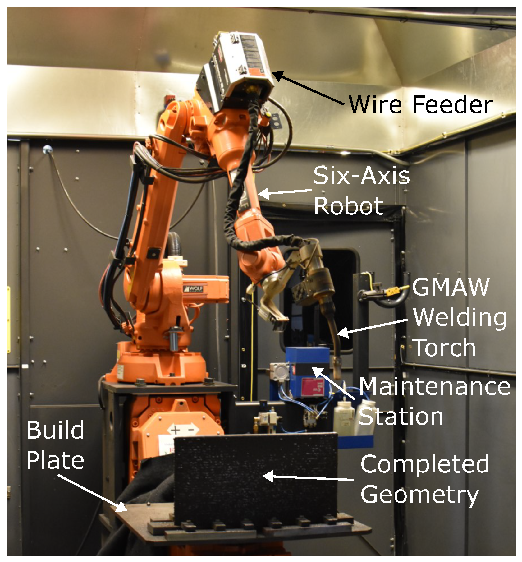
2.1. The WAAM Process
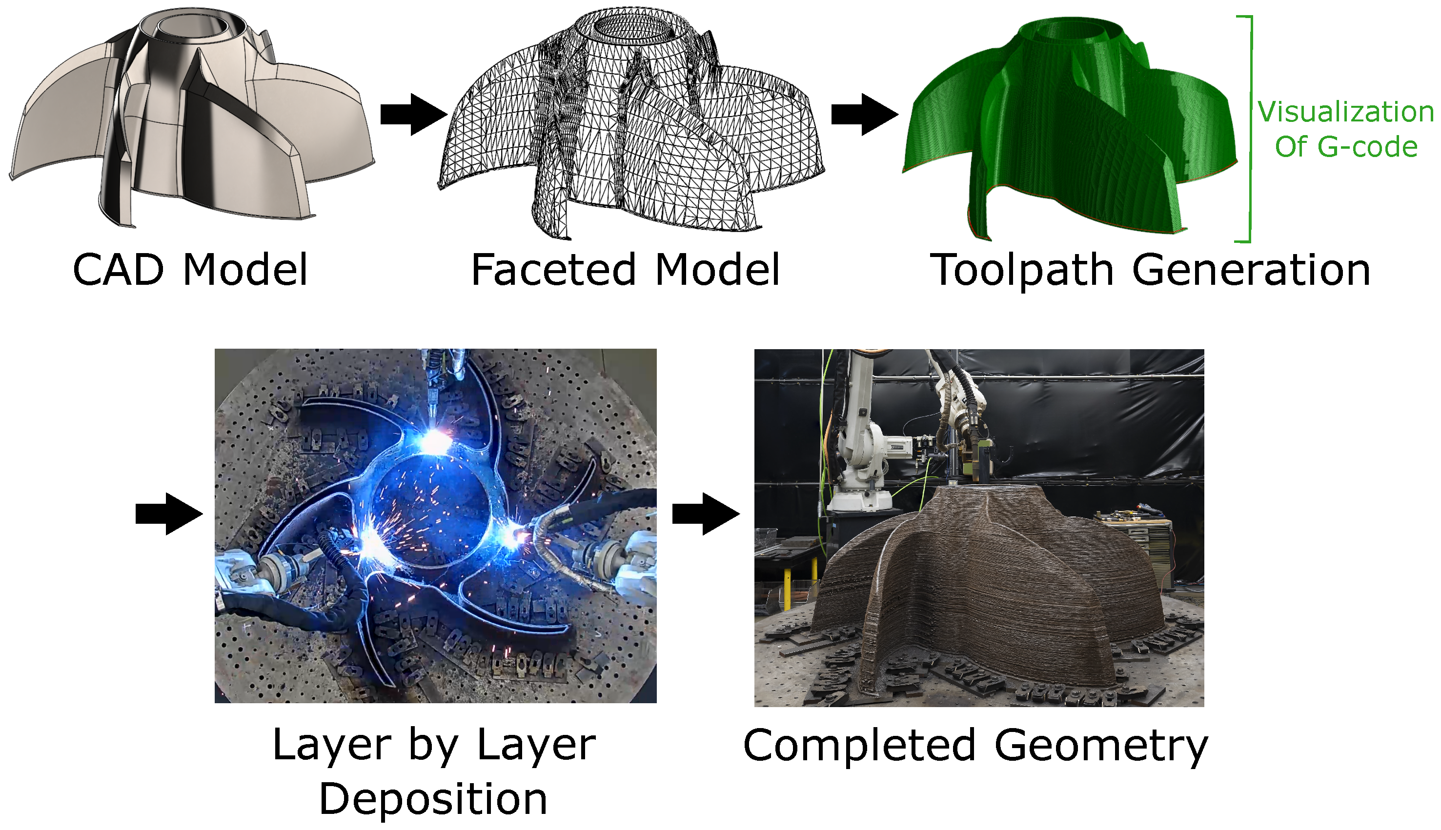
2.2. CAD to Part Process
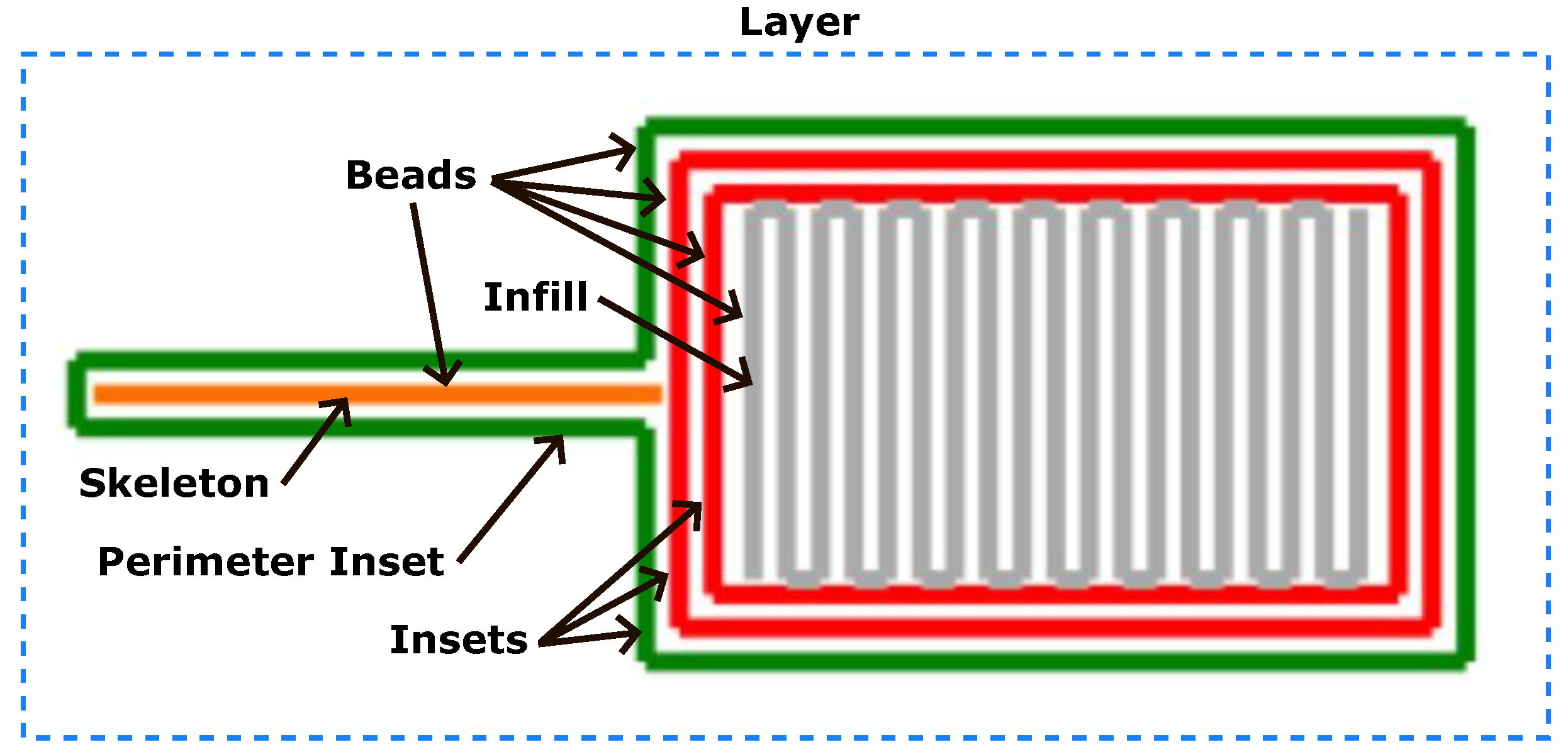
2.3. Slicing and Toolpath Generation
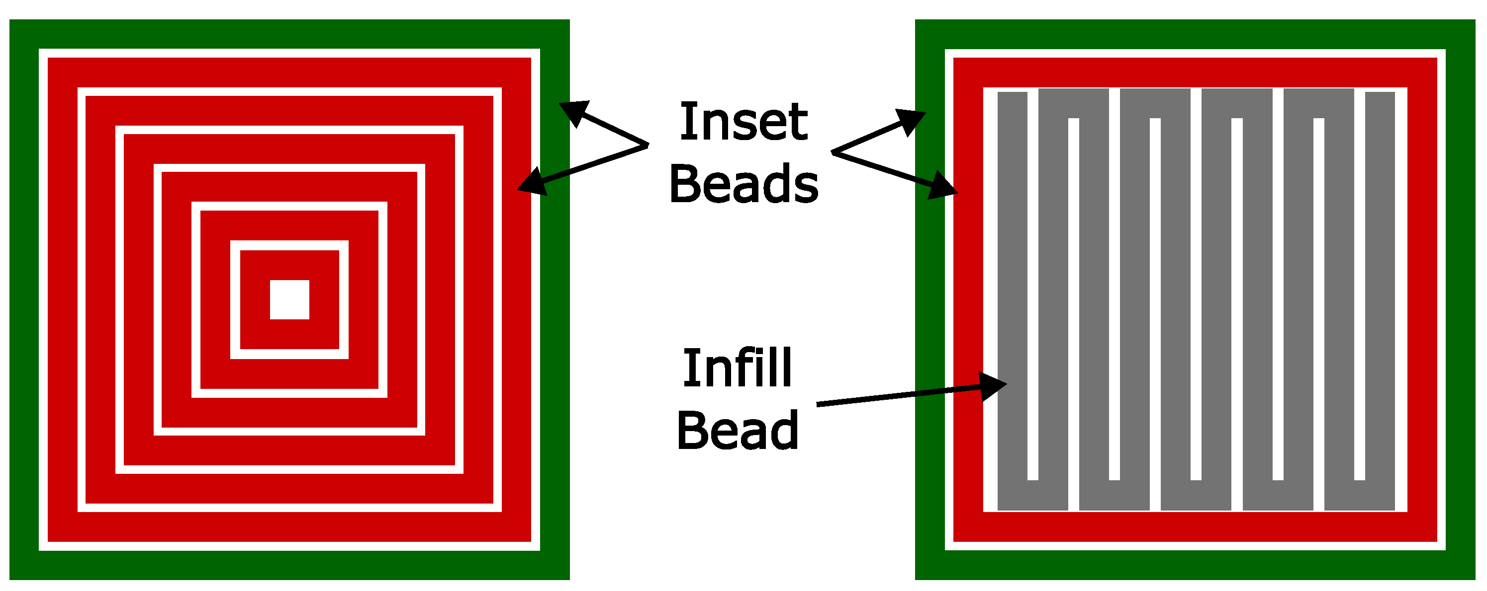
2.3.1. Insets
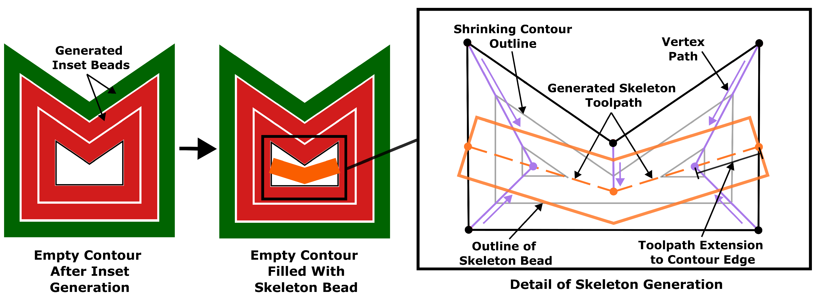
2.3.2. Skeletons
2.3.3. Infill
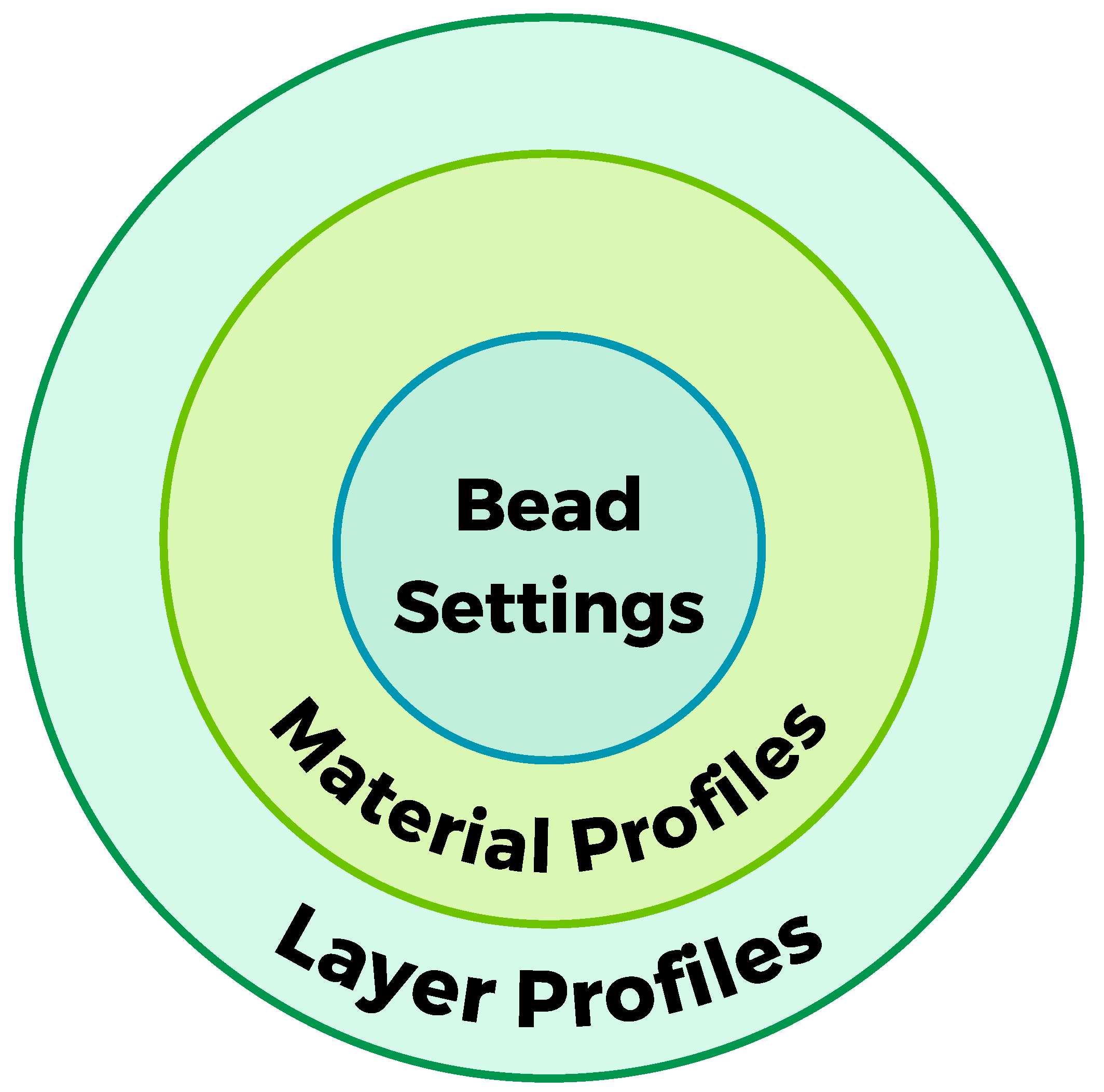
2.4. Slicing Hierarchy
2.5. G-Code Generation
3. Slicing Considerations and Solutions
3.1. Geometric Considerations
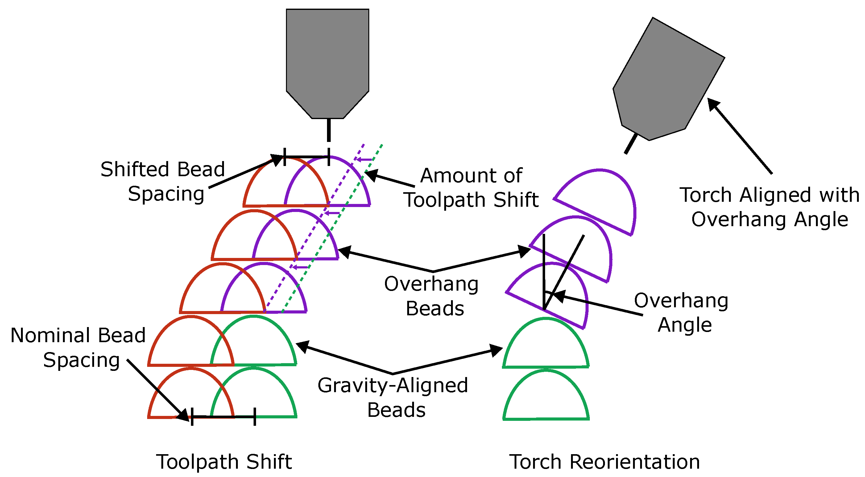
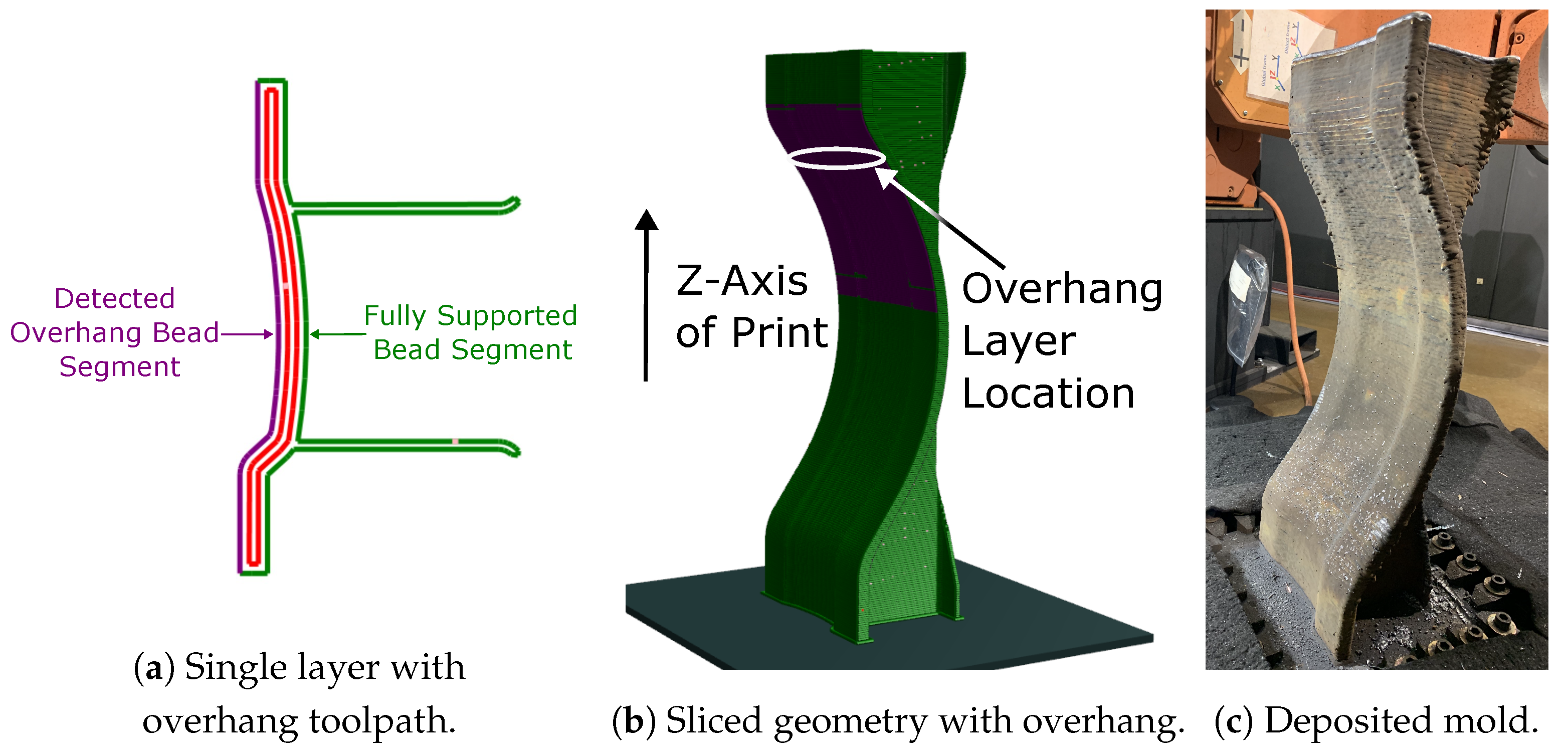
3.1.1. Overhang Compensation
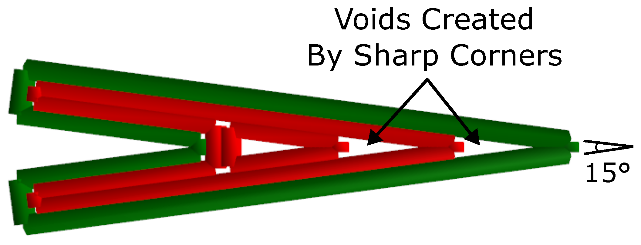
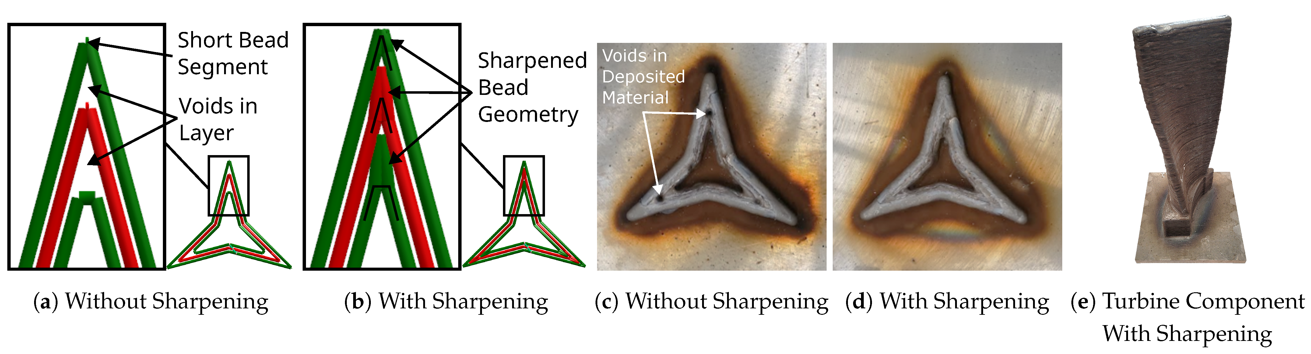
3.1.2. Corner Sharpening
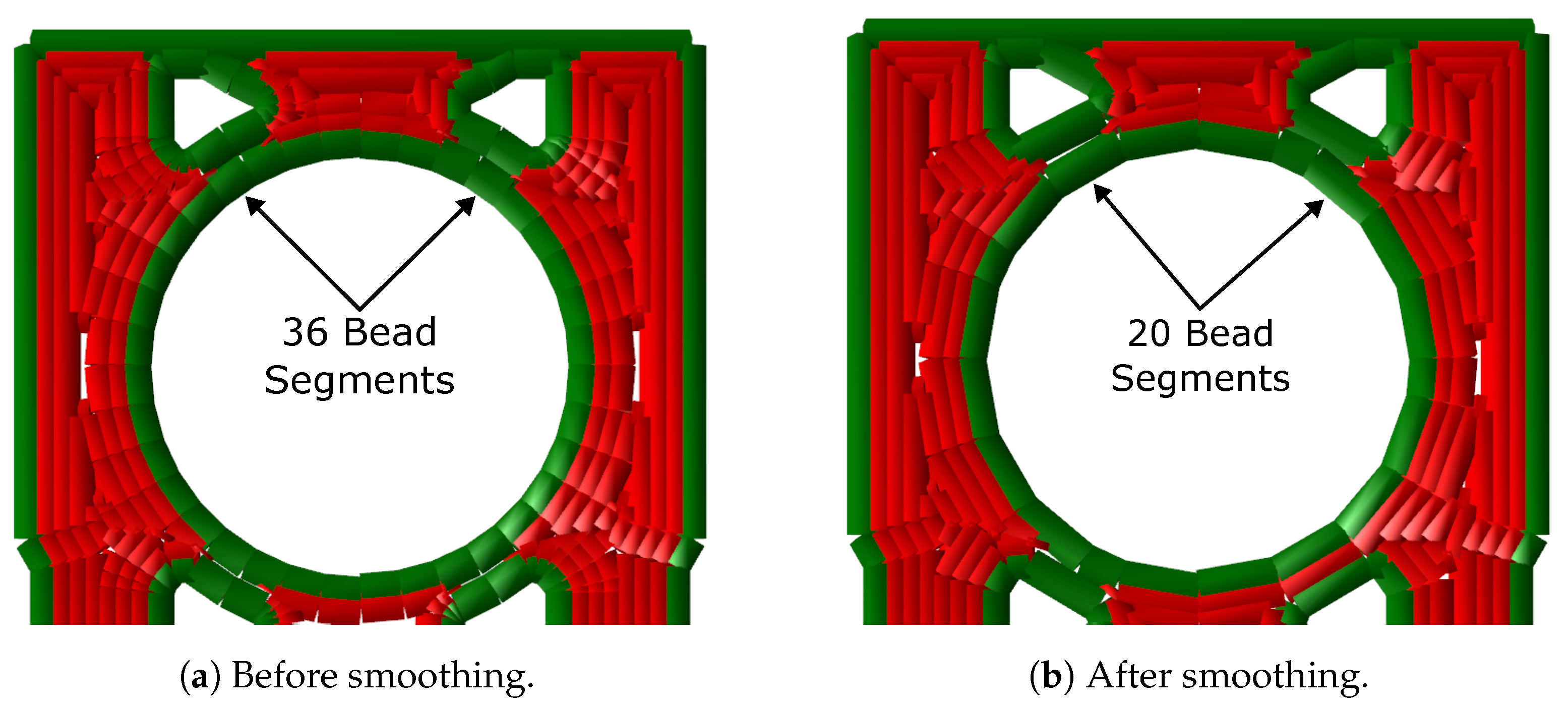
3.1.3. Smoothing
3.2. Process Considerations
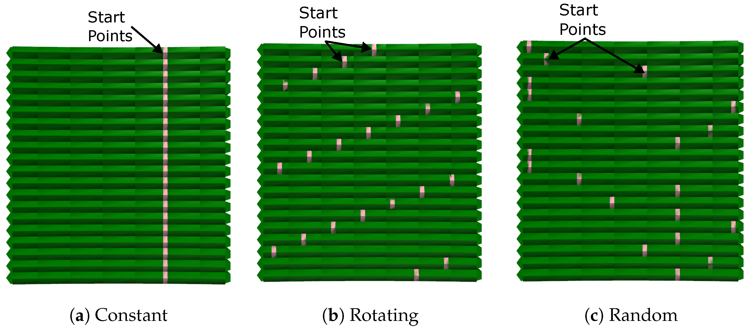
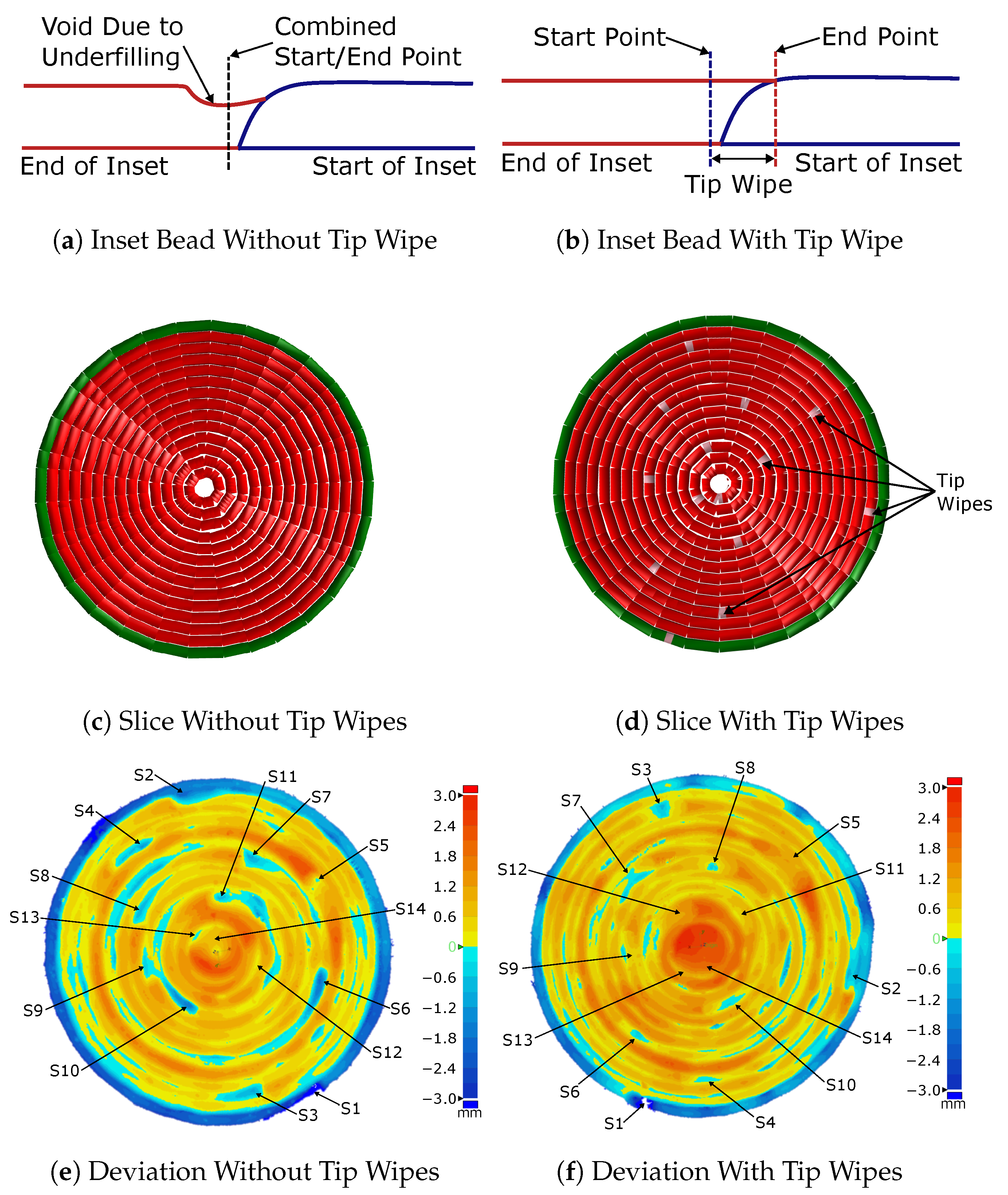
3.2.1. Start Point Configuration
3.2.2. Control of Bead Segment End Points
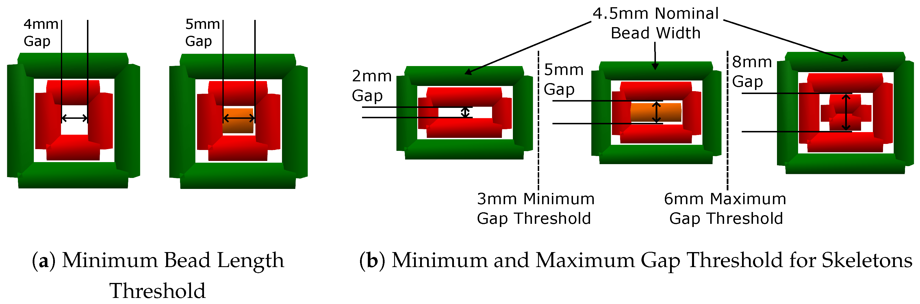
3.2.3. Control of Bead Lengths
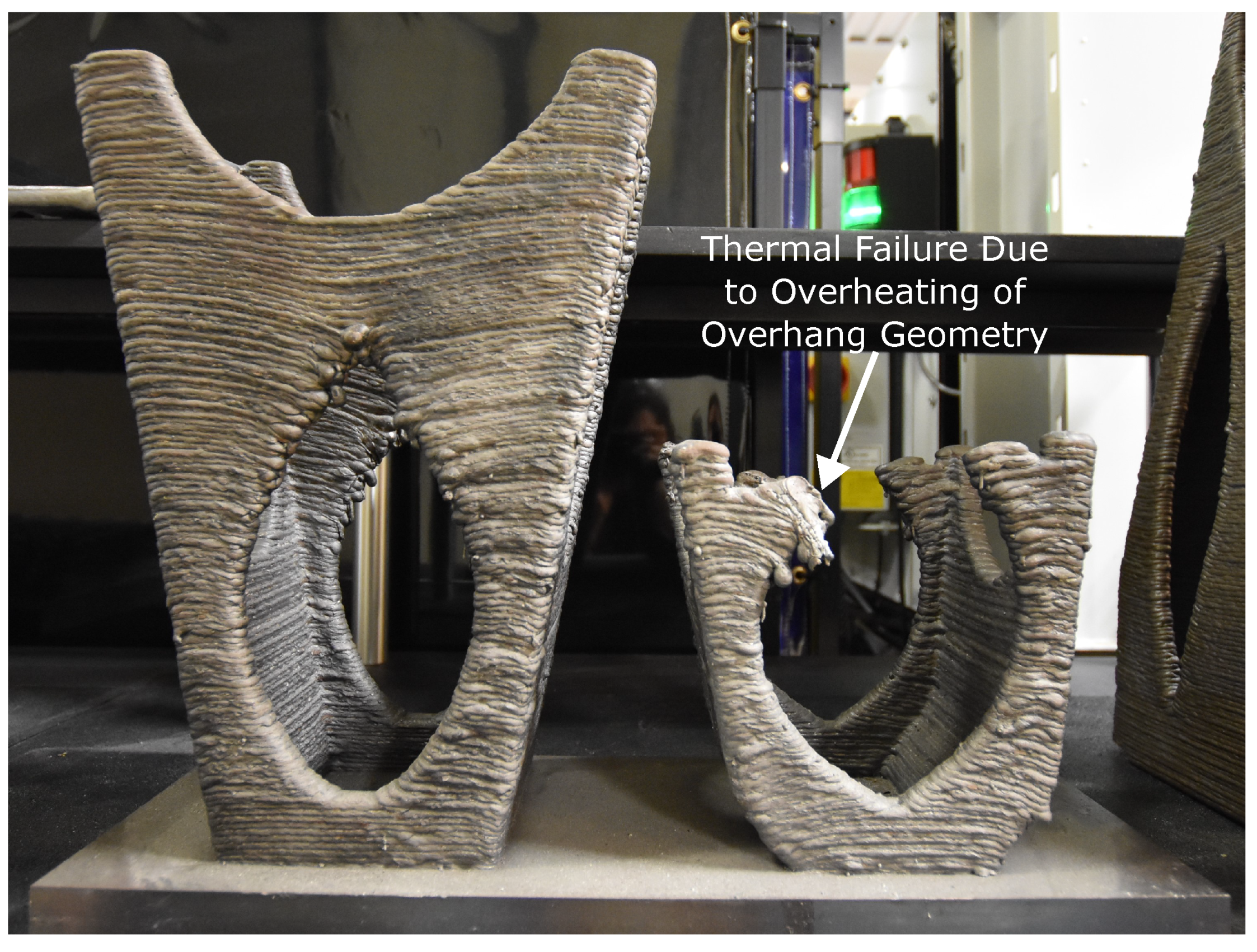
3.3. Thermal Considerations
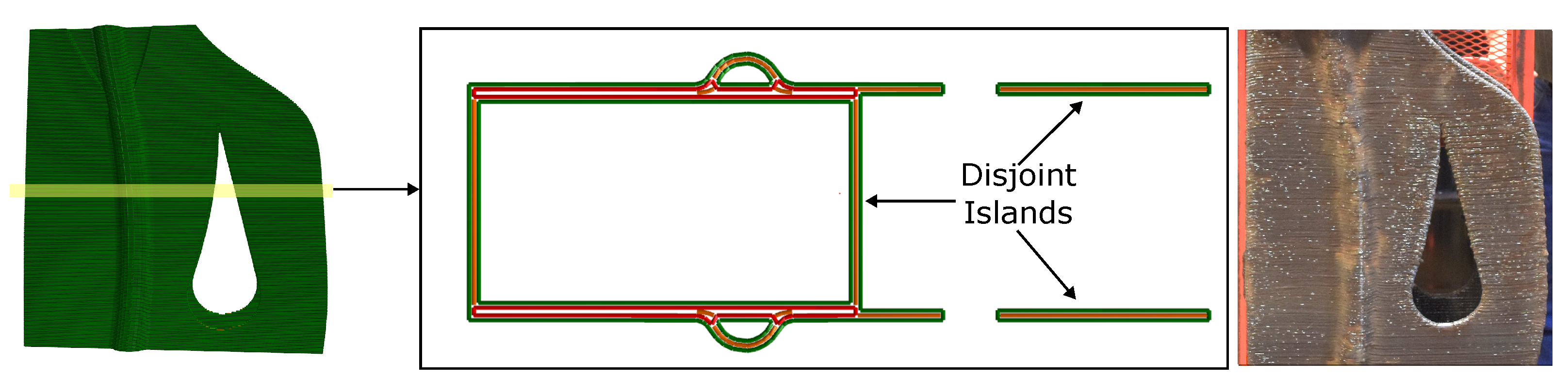
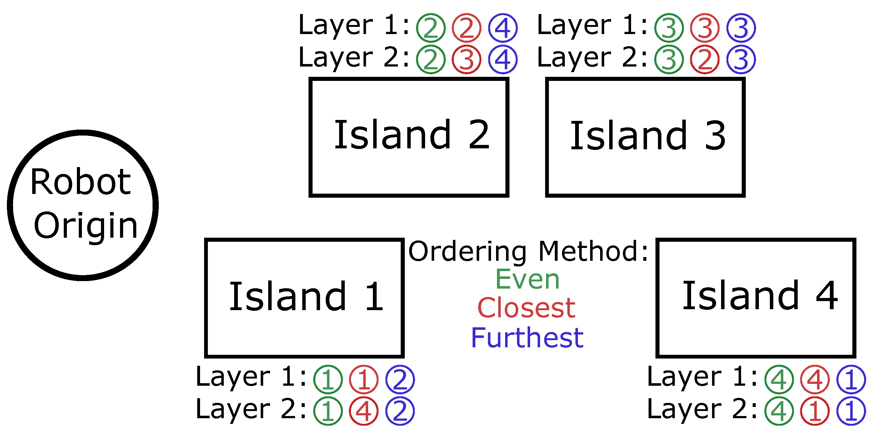
Island Optimization
3.4. Productivity Considerations
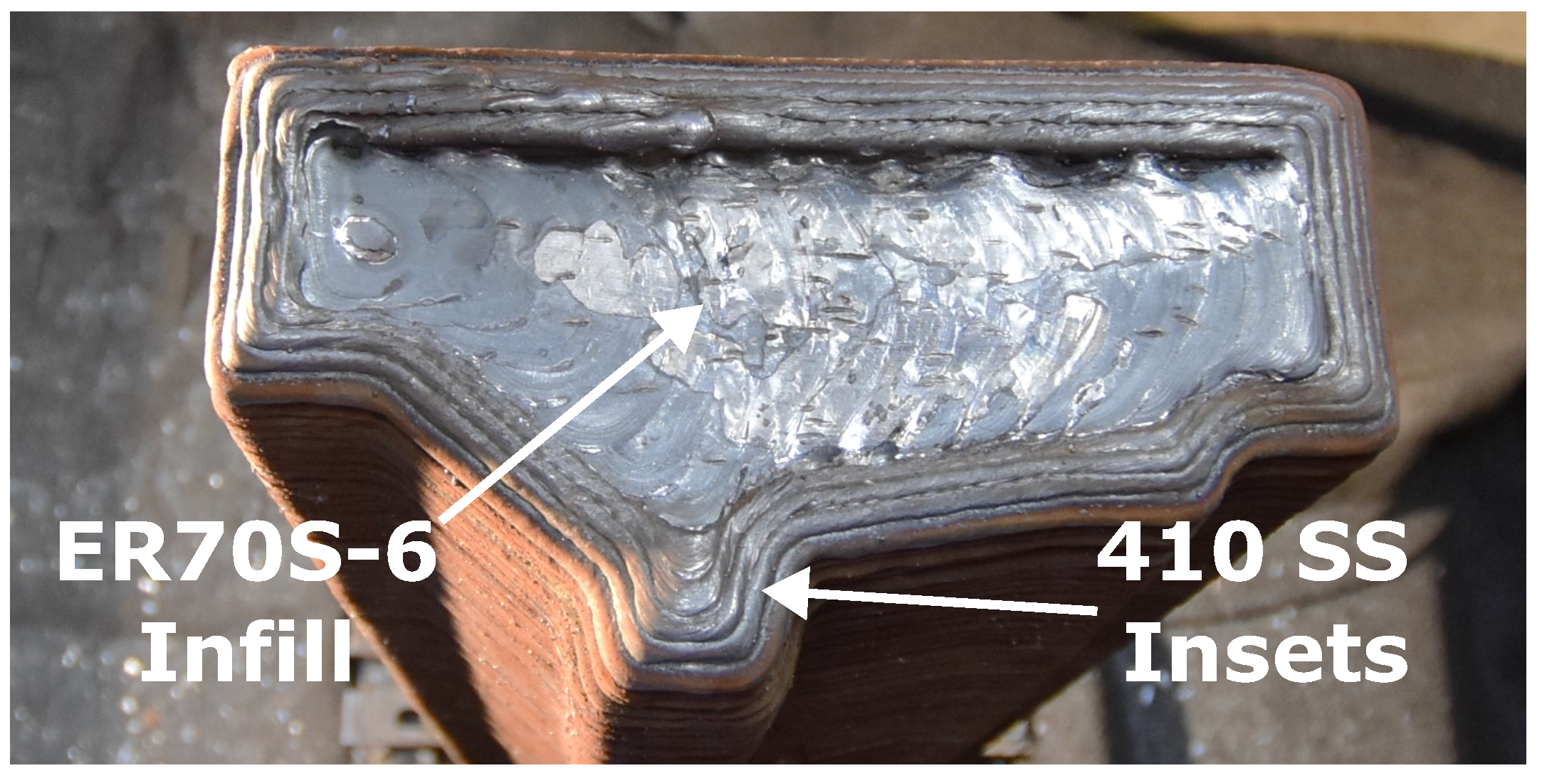
3.4.1. Multi-Material Printing
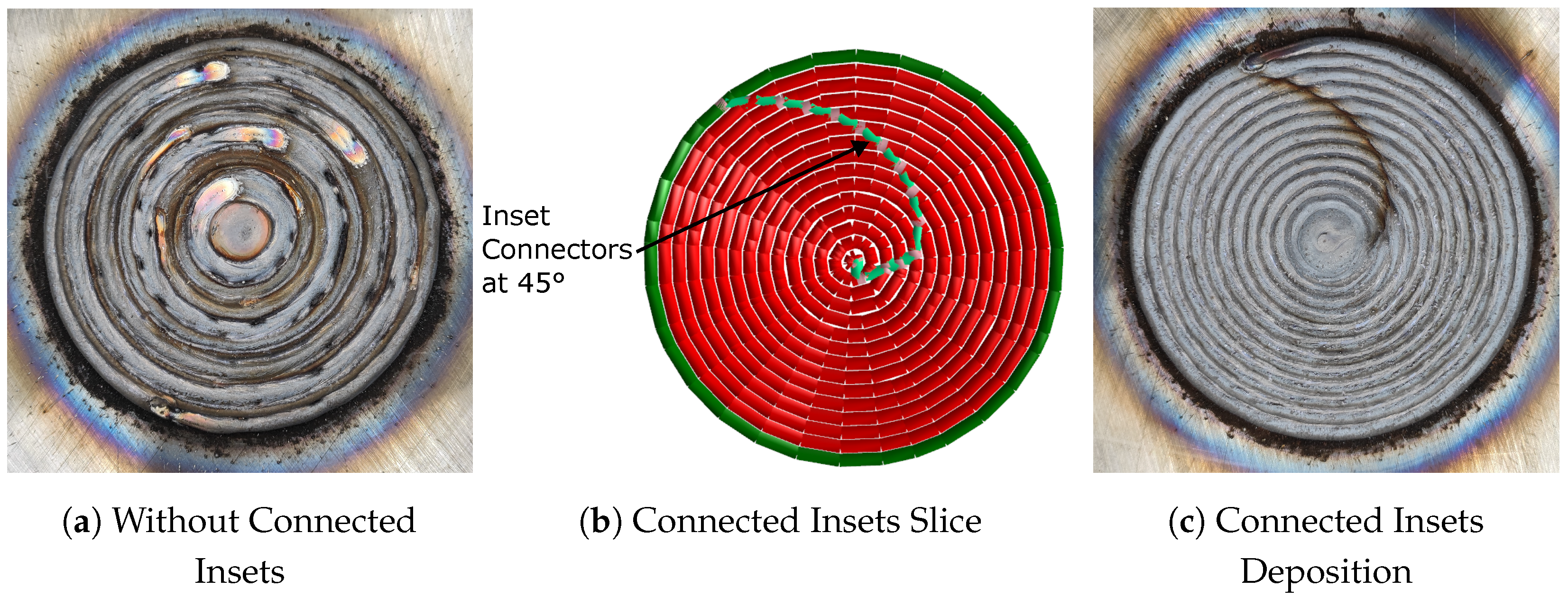
3.4.2. Increasing Productivity with Connected Insets
3.5. Solutions for Post-Processing
3.5.1. G-Code Splicing Tools
3.5.2. UI Tools for User Tuning of G-Code
4. Conclusions
Author Contributions
Funding
Institutional Review Board Statement
Data Availability Statement
Acknowledgments
Conflicts of Interest
Abbreviations
| WAAM | Wire arc additive manufacturing |
| FDM | Fused deposition modeling |
| GMAW | Gas metal arc welding |
| GTAW | Gas tungsten arc welding |
| PAW | Plasma arc welding |
| CAD | Computer-aided design |
| STL | Stereolithographic |
| ORNL | Oak Ridge National Laboratory |
References
- Cunningham, C.; Flynn, J.; Shokrani, A.; Dhokia, V.; Newman, S. Invited review article: Strategies and processes for high quality wire arc additive manufacturing. Addit. Manuf. 2018, 22, 672–686. [Google Scholar] [CrossRef]
- Treutler, K.; Wesling, V. The Current State of Research of Wire Arc Additive Manufacturing (WAAM): A Review. Appl. Sci. 2021, 11, 8619. [Google Scholar] [CrossRef]
- Arbogast, A.; Nycz, A.; Noakes, M.W.; Wang, P.; Masuo, C.; Vaughan, J.; Love, L.; Lind, R.; Carter, W.; Meyer, L.; et al. Strategies for a scalable multi-robot large scale wire arc additive manufacturing system. Addit. Manuf. Lett. 2024, 8, 100183. [Google Scholar] [CrossRef]
- Nilsiam, Y.; Sanders, P.G.; Pearce, J.M. Applications of Open Source GMAW-Based Metal 3-D Printing. J. Manuf. Mater. Process. 2018, 2, 18. [Google Scholar] [CrossRef]
- Rauch, M.; Hascoet, J.Y.; Querard, V. A Multiaxis Tool Path Generation Approach for Thin Wall Structures Made with WAAM. J. Manuf. Mater. Process. 2021, 5, 128. [Google Scholar] [CrossRef]
- Singh, S.; kumar Sharma, S.; Rathod, D.W. A review on process planning strategies and challenges of WAAM. Mater. Today Proc. 2021, 47, 6564–6575. [Google Scholar] [CrossRef]
- Venturini, G.; Montevecchi, F.; Bandini, F.; Scippa, A.; Campatelli, G. Feature based three axes computer aided manufacturing software for wire arc additive manufacturing dedicated to thin walled components. Addit. Manuf. 2018, 22, 643–657. [Google Scholar] [CrossRef]
- Nilsiam, Y.; Sanders, P.; Pearce, J.M. Slicer and process improvements for open-source GMAW-based metal 3-D printing. Addit. Manuf. 2017, 18, 110–120. [Google Scholar] [CrossRef]
- Aldalur, E.; Veiga, F.; Suárez, A.; Bilbao, J.; Lamikiz, A. High deposition wire arc additive manufacturing of mild steel: Strategies and heat input effect on microstructure and mechanical properties. J. Manuf. Process. 2020, 58, 615–626. [Google Scholar] [CrossRef]
- Yıldız, A.; Davut, K.; Koc, B.; Yılmaz, O. Wire arc additive manufacturing of high-strength low alloy steels: Study of process parameters and their influence on the bead geometry and mechanical characteristics. Int. J. Adv. Manuf. Technol. 2020, 108, 3391–3404. [Google Scholar] [CrossRef]
- Caballero, A.; Ding, J.; Ganguly, S.; Williams, S. Wire + Arc Additive Manufacture of 17-4 PH stainless steel: Effect of different processing conditions on microstructure, hardness, and tensile strength. J. Mater. Process. Technol. 2019, 268, 54–62. [Google Scholar] [CrossRef]
- Zhao, Y.; Chen, Y.; Wang, Z.; Ye, J.; Zhao, W. Mechanical properties, microstructural characteristics and heat treatment effects of WAAM stainless-steel plate material. J. Build. Eng. 2023, 75, 106988. [Google Scholar] [CrossRef]
- Jafari, D.; Vaneker, T.H.; Gibson, I. Wire and arc additive manufacturing: Opportunities and challenges to control the quality and accuracy of manufactured parts. Mater. Des. 2021, 202, 109471. [Google Scholar] [CrossRef]
- Teixeira, F.R.; Jorge, V.L.; Scotti, F.M.; Siewert, E.; Scotti, A. A Methodology for Shielding-Gas Selection in Wire Arc Additive Manufacturing with Stainless Steel. Materials 2024, 17, 3328. [Google Scholar] [CrossRef]
- Khan, A.; Chatterjee, S.; Madhukar, Y. TIG Assisted Surface Finish Enhancement in MIG-based Wire Arc Additive Manufacturing. Manuf. Lett. 2024, 40, 26–30. [Google Scholar] [CrossRef]
- Hu, J. Study on STL-Based Slicing Process for 3D Printing. In Proceedings of the 28th Annual International Solid Freeform Fabrication Symposium, Austin, TX, USA, 7–9 August 2017. [Google Scholar]
- Aksoy, D.; Balta, E.C.; Tilbury, D.M.; Barton, K. A Control-Oriented Model for Bead Cross-Sectional Geometry in Fused Deposition Modeling. In Proceedings of the 2020 American Control Conference (ACC), Denver, CO, USA, 1–3 July 2020; pp. 474–480. [Google Scholar] [CrossRef]
- Messing, A.; Roschli, A.; Post, B.K.; Love, L.J. Using Skeletons for Void Filling in Large-Scale Additive Manufacturing. In Proceedings of the 28th Annual International Solid Freeform Fabrication Symposium, Austin, TX, USA, 7–9 August 2017. [Google Scholar]
- Aichholzer, O.; Aurenhammer, F.; Alberts, D.; Gärtner, B. A Novel Type of Skeleton for Polygons. In J.UCS The Journal of Universal Computer Science: Annual Print and CD-ROM Archive Edition Volume 1 • 1995; Maurer, H., Calude, C., Salomaa, A., Eds.; Springer: Berlin/Heidelberg, Germany, 1996; pp. 752–761. [Google Scholar] [CrossRef]
- Aichholzer, O.; Aurenhammer, F. Straight skeletons for general polygonal figures in the plane. In Proceedings of the Computing and Combinatorics; Cai, J.Y., Wong, C.K., Eds.; Springer: Berlin/Heidelberg, Germany, 1996; pp. 117–126. [Google Scholar]
- Ding, D.; Pan, Z.; Cuiuri, D.; Li, H. A multi-bead overlapping model for robotic wire and arc additive manufacturing (WAAM). Robot. Comput. Integr. Manuf. 2015, 31, 101–110. [Google Scholar] [CrossRef]
- Jiang, J.; Xu, X.; Stringer, J. Support Structures for Additive Manufacturing: A Review. J. Manuf. Mater. Process. 2018, 2, 64. [Google Scholar] [CrossRef]
- Greer, C.; Nycz, A.; Noakes, M.; Richardson, B.; Post, B.; Kurfess, T.; Love, L. Introduction to the design rules for metal big area additive manufacturing. Addit. Manuf. 2019, 27, 159–166. [Google Scholar] [CrossRef]
- McNeil, J.L.; Hamel, W.R.; Penney, J.; Nycz, A.; Noakes, M. Framework for CAD to Part of Large Scale Additive Manufacturing of Metal (LSAMM) in Arbitrary Directions. In Proceedings of the 30th Annual International Solid Freeform Fabrication Symposium, Austin, TX, USA, 12–14 August 2019. [Google Scholar]
- Yu, R.; Yu, S.; Yu, Z.; Zheng, B. Directed energy deposition-arc of thin-walled aerobat shell with structures of internal ribs and overhanging gaps. Int. J. Adv. Manuf. Technol. J. Adv. Manuf. Technol. 2023, 127, 305–321. [Google Scholar] [CrossRef]
- Evjemo, L.D.; Langelandsvik, G.; Moe, S.; Danielsen, M.H.; Gravdahl, J.T. Wire-arc additive manufacturing of structures with overhang: Experimental results depositing material onto fixed substrate. CIRP J. Manuf. Sci. Technol. 2022, 38, 186–203. [Google Scholar] [CrossRef]
- Slavíček, J.; Franke, J.; Jaroš, J.; Koutný, D. Strategies for wire arc additive manufacturing of thin walls and overhangs. J. Mech. Sci. Technol. 2023, 37, 5529–5534. [Google Scholar] [CrossRef]
- Liu, H.H.; Zhao, T.; Li, L.Y.; Liu, W.J.; Wang, T.Q.; Yue, J.F. A path planning and sharp corner correction strategy for wire and arc additive manufacturing of solid components with polygonal cross-sections. Int. J. Adv. Manuf. Technol. 2020, 106, 4879–4889. [Google Scholar] [CrossRef]
- Ding, D.; Yuan, L.; Huang, R.; Jiang, Y.; Wang, X.; Pan, Z. Corner path optimization strategy for wire arc additive manufacturing of gap-free shapes. J. Manuf. Process. 2023, 85, 683–694. [Google Scholar] [CrossRef]
- Douglas, D.H.; Peucker, T.K. Algorithms for the reduction of the number of points required to represent a digitized line or its caricature. Cartographica 1973, 10, 112–122. [Google Scholar] [CrossRef]
- Tang, S.; Wang, G.; Huang, C.; Zhang, H. Investigation and Control of Weld Bead at Both Ends in WAAM. In Proceedings of the 30th Annual International Solid Freeform Fabrication Symposium, Austin, TX, USA, 12–14 August 2019. [Google Scholar] [CrossRef]
- Oh, W.J.; Lee, C.M.; Kim, D.H. Prediction of deposition bead geometry in wire arc additive manufacturing using machine learning. J. Mater. Res. Technol. 2022, 20, 4283–4296. [Google Scholar] [CrossRef]
- Zou, R.; Xia, Y.; Liu, S.; Hu, P.; Hou, W.; Hu, Q.; Shan, C. Isotropic and anisotropic elasticity and yielding of 3D printed material. Compos. Part B Eng. 2016, 99, 506–513. [Google Scholar] [CrossRef]
- Ding, D.; He, F.; Yuan, L.; Pan, Z.; Wang, L.; Ros, M. The first step towards intelligent wire arc additive manufacturing: An automatic bead modelling system using machine learning through industrial information integration. J. Ind. Inf. Integr. 2021, 23, 100218. [Google Scholar] [CrossRef]
- Pan, Z.; Ding, D.; Wu, B.; Cuiuri, D.; Li, H.; Norrish, J. Arc Welding Processes for Additive Manufacturing: A Review. In Transactions on Intelligent Welding Manufacturing; Chen, S., Zhang, Y., Feng, Z., Eds.; Springer: Singapore, 2018; pp. 3–24. [Google Scholar]
- Rosli, N.A.; Alkahari, M.R.; bin Abdollah, M.F.; Maidin, S.; Ramli, F.R.; Herawan, S.G. Review on effect of heat input for wire arc additive manufacturing process. J. Mater. Res. Technol. 2021, 11, 2127–2145. [Google Scholar] [CrossRef]
- Zhao, Y.; Jia, Y.; Chen, S.; Shi, J.; Li, F. Process planning strategy for wire-arc additive manufacturing: Thermal behavior considerations. Addit. Manuf. 2020, 32, 100935. [Google Scholar] [CrossRef]
- Němec, J.; Kunčická, L.; Opěla, P.; Dvořák, K. Determining Hot Deformation Behavior and Rheology Laws of Selected Austenitic Stainless Steels. Metals 2023, 13, 1902. [Google Scholar] [CrossRef]
- Carter, W.; Masuo, C.; Nycz, A.; Noakes, M.; Vaughan, D. Thermal process monitoring for wire-arc additive manufacturing using IR cameras. In Proceedings of the 30th Annual International Solid Freeform Fabrication Symposium, Austin, TX, USA, 12–14 August 2019. [Google Scholar]
- Treutler, K.; Kamper, S.; Leicher, M.; Bick, T.; Wesling, V. Multi-Material Design in Welding Arc Additive Manufacturing. Metals 2019, 9, 809. [Google Scholar] [CrossRef]
- Zhang, C.; Yu, H.; Sun, D.; Liu, W. Fabrication of Multi-Material Components by Wire Arc Additive Manufacturing. Coatings 2022, 12, 1683. [Google Scholar] [CrossRef]
- Banaee, A.; Kapil, A.; Sharma, A. Process design for multi-material wire arc additive manufacturing. In Proceedings of the 76th IIW Annual Assembly and International Conference on Welding and Joining, Singapore, 16–20 July 2023. [Google Scholar]
- Sridar, S.; Klecka, M.A.; Xiong, W. Interfacial characteristics of P91 steel-Inconel 740H bimetallic structure fabricated using wire-arc additive manufacturing. J. Mater. Process. Technol. 2022, 300, 117396. [Google Scholar]
- Wu, B.; Qiu, Z.; Pan, Z.; Carpenter, K.; Wang, T.; Ding, D.; Duin, S.V.; Li, H. Enhanced interface strength in steel-nickel bimetallic component fabricated using wire arc additive manufacturing with interweaving deposition strategy. J. Mater. Sci. Technol. 2020, 52, 226–234. [Google Scholar] [CrossRef]


| Without Tip Wipes | With Tip Wipes | Reduction in Deviation | |
|---|---|---|---|
| Average Maximum Deviation at Start Points: | −0.98 mm | −0.32 mm | 67% |
| Std. Deviation from Nominal Surface: | 0.96 mm | 0.86 mm | 10% |
| Without Connected Insets | Connected Insets | Reduction in Time | |
|---|---|---|---|
| With Wire Cuts: | 487 s | 234 s | 52% |
| Without Wire Cuts: | 364 s | 218 s | 40% |
Disclaimer/Publisher’s Note: The statements, opinions and data contained in all publications are solely those of the individual author(s) and contributor(s) and not of MDPI and/or the editor(s). MDPI and/or the editor(s) disclaim responsibility for any injury to people or property resulting from any ideas, methods, instructions or products referred to in the content. |
© 2025 by the authors. Licensee MDPI, Basel, Switzerland. This article is an open access article distributed under the terms and conditions of the Creative Commons Attribution (CC BY) license (https://creativecommons.org/licenses/by/4.0/).
Share and Cite
Sebok, M.; Lai, C.; Masuo, C.; Walters, A.; Carter, W.; Lambert, N.; Meyer, L.; Officer, J.; Roschli, A.; Vaughan, J.; et al. Slicing Solutions for Wire Arc Additive Manufacturing. J. Manuf. Mater. Process. 2025, 9, 112. https://doi.org/10.3390/jmmp9040112
Sebok M, Lai C, Masuo C, Walters A, Carter W, Lambert N, Meyer L, Officer J, Roschli A, Vaughan J, et al. Slicing Solutions for Wire Arc Additive Manufacturing. Journal of Manufacturing and Materials Processing. 2025; 9(4):112. https://doi.org/10.3390/jmmp9040112
Chicago/Turabian StyleSebok, Michael, Canhai Lai, Chris Masuo, Alex Walters, William Carter, Nathan Lambert, Luke Meyer, Jake Officer, Alex Roschli, Joshua Vaughan, and et al. 2025. "Slicing Solutions for Wire Arc Additive Manufacturing" Journal of Manufacturing and Materials Processing 9, no. 4: 112. https://doi.org/10.3390/jmmp9040112
APA StyleSebok, M., Lai, C., Masuo, C., Walters, A., Carter, W., Lambert, N., Meyer, L., Officer, J., Roschli, A., Vaughan, J., & Nycz, A. (2025). Slicing Solutions for Wire Arc Additive Manufacturing. Journal of Manufacturing and Materials Processing, 9(4), 112. https://doi.org/10.3390/jmmp9040112