Z-Stitching Technique for Improved Mechanical Performance in Fused Filament Fabrication


Abstract
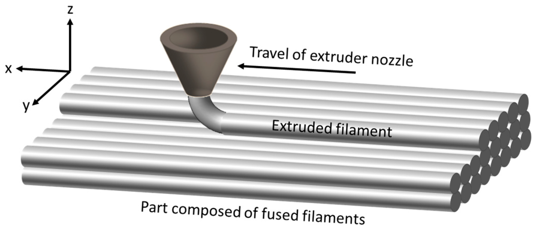
1. Introduction
2. Description of Z-Stitching Technique
2.1. Overview
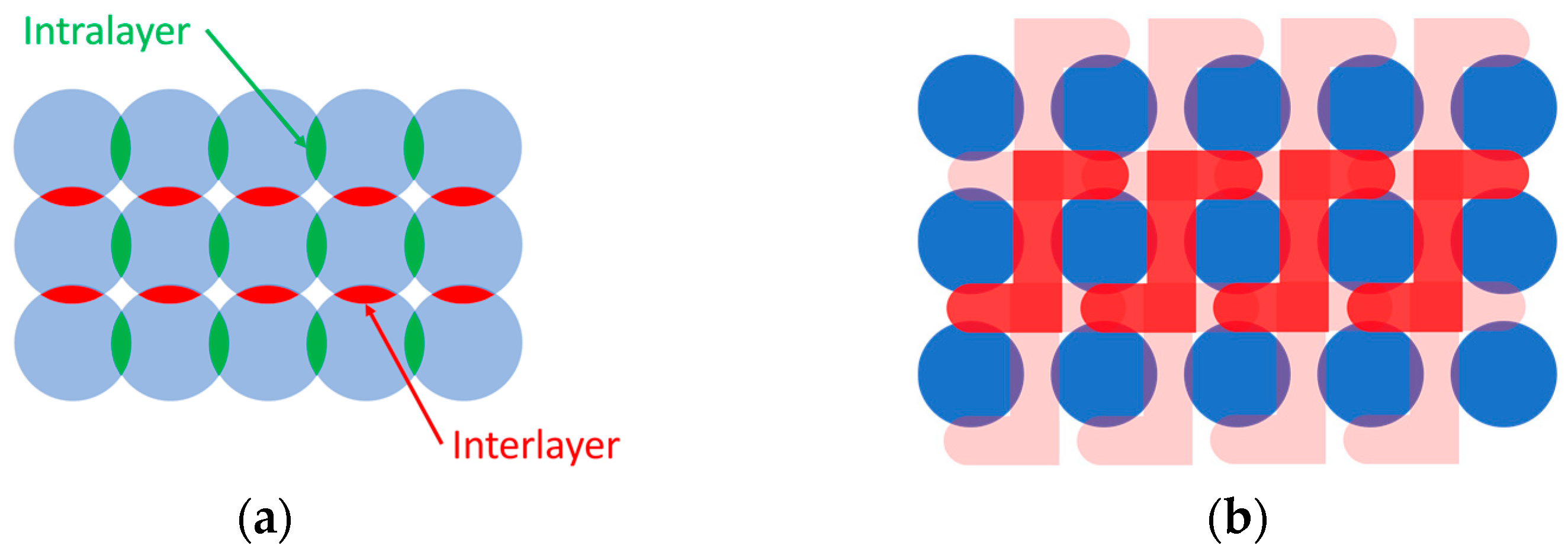
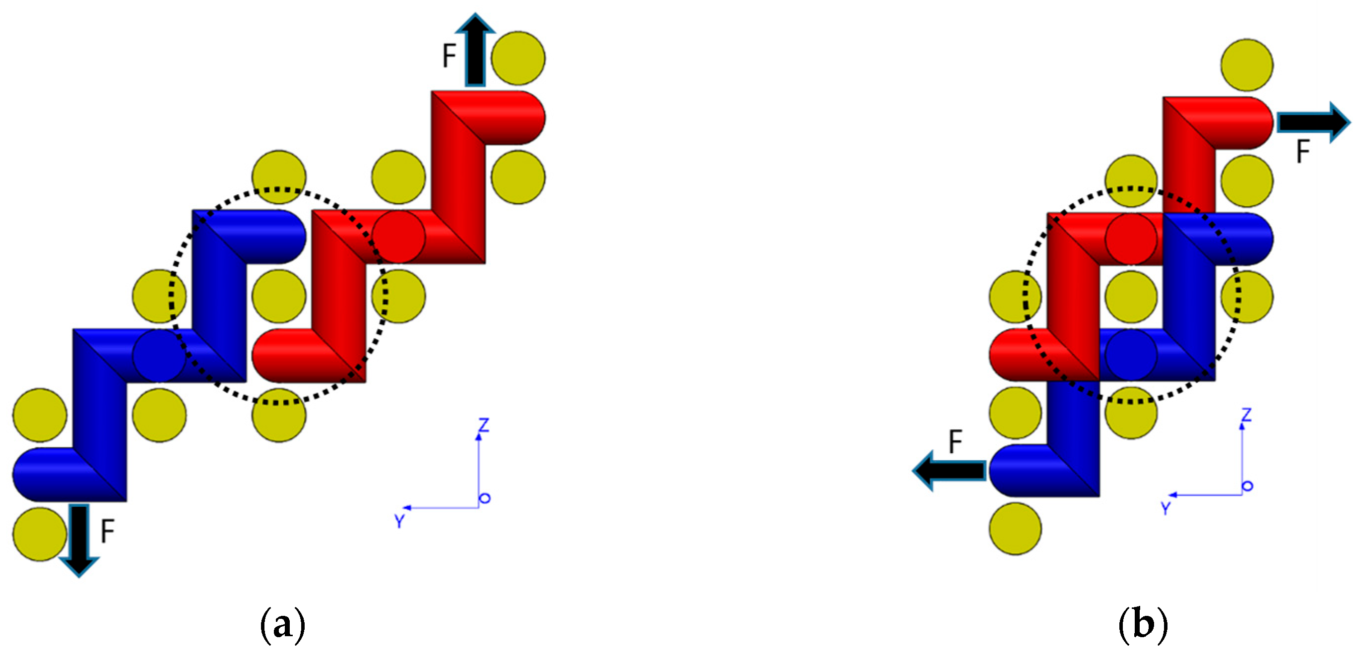
2.2. Interlocking of Layers
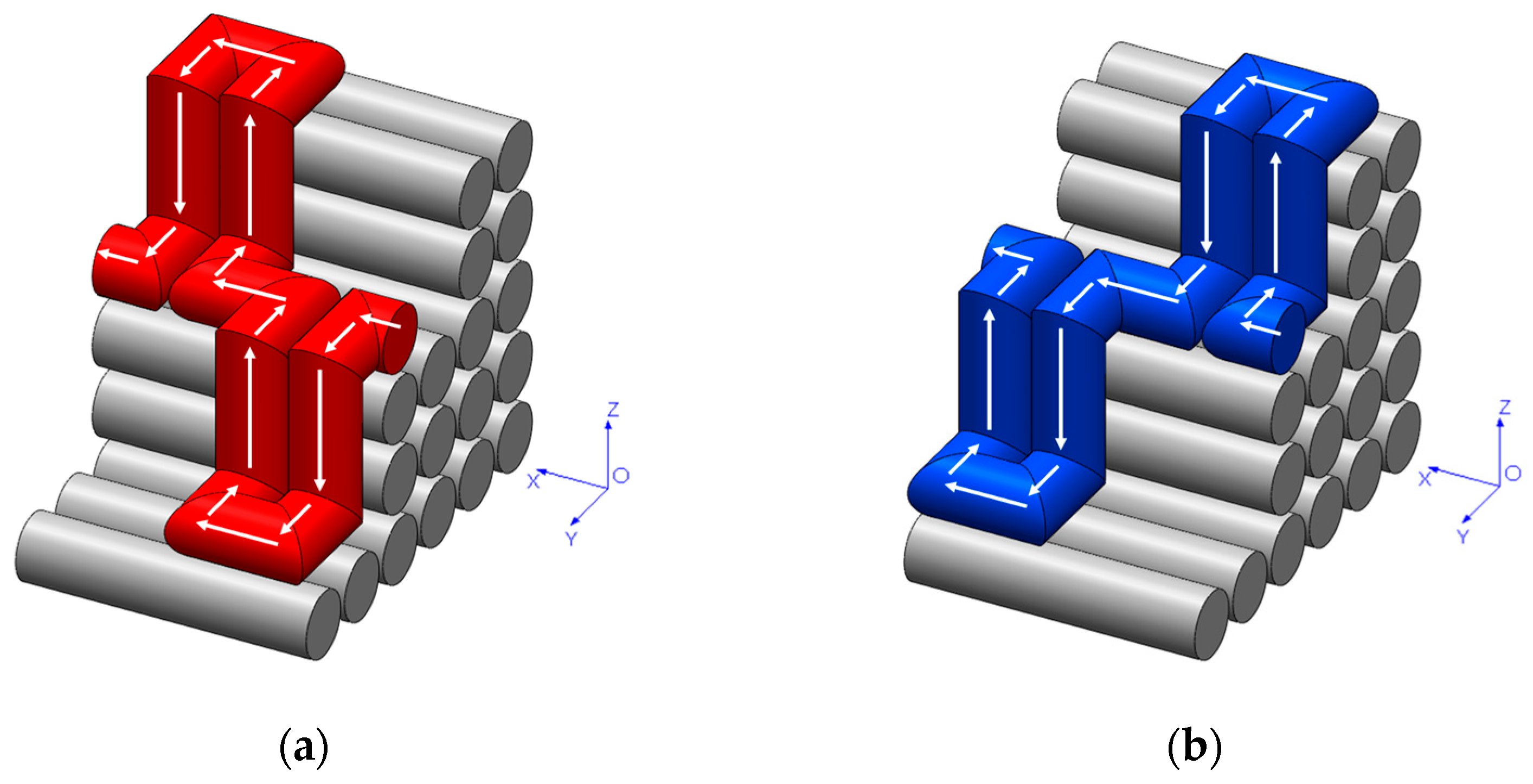
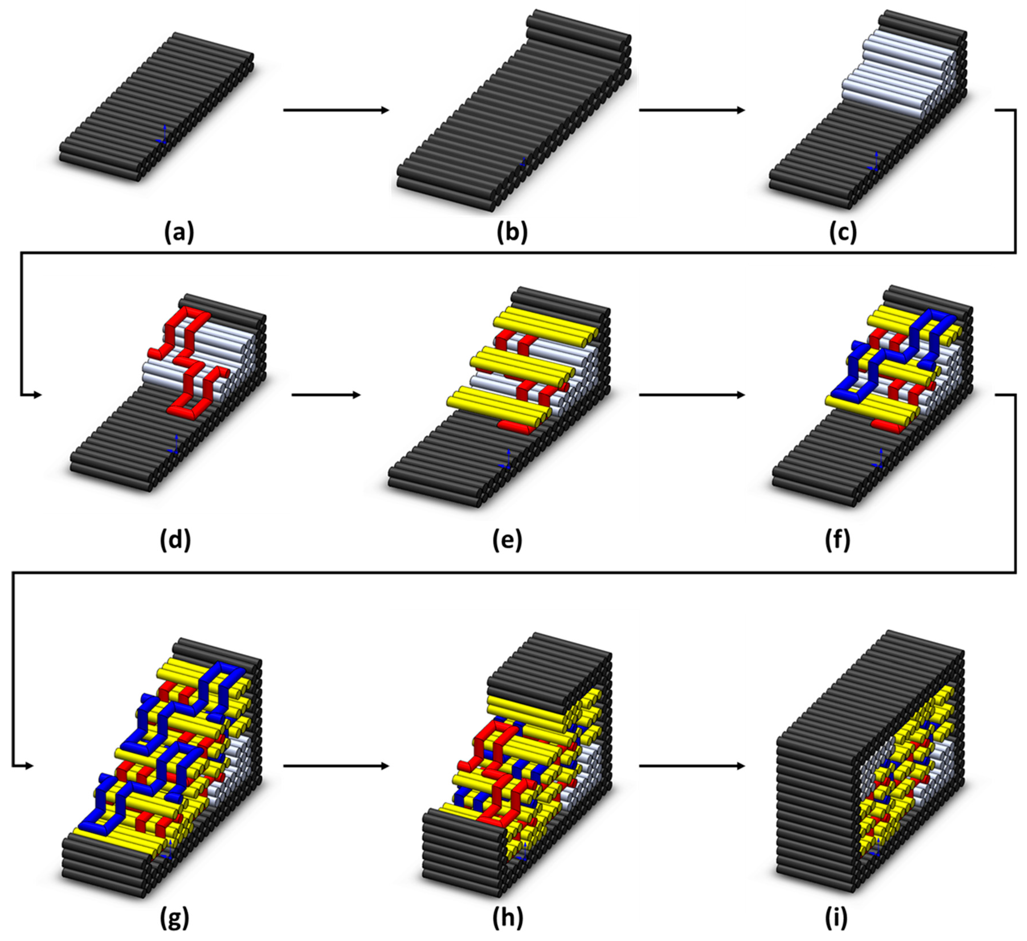
2.3. Printing Sequence
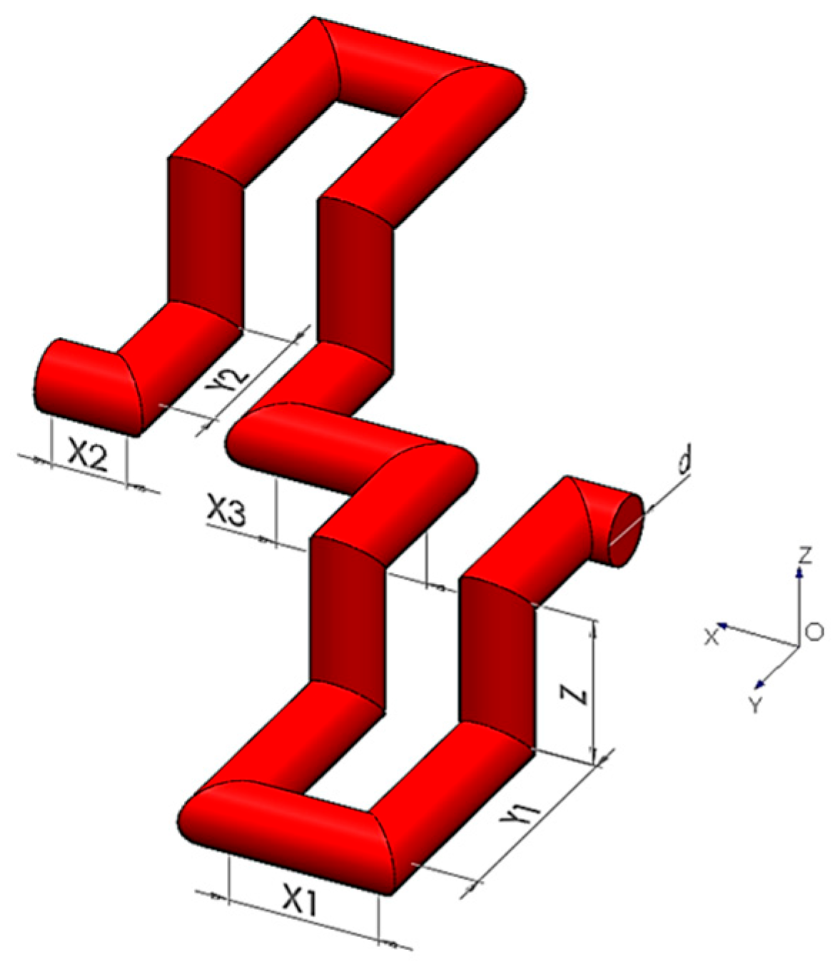
2.4. Stitch Dimensions and Toolpath Planning
3. Materials and Experimental Methods
3.1. Materials and Printing Equipment
3.2. Experimental Methods
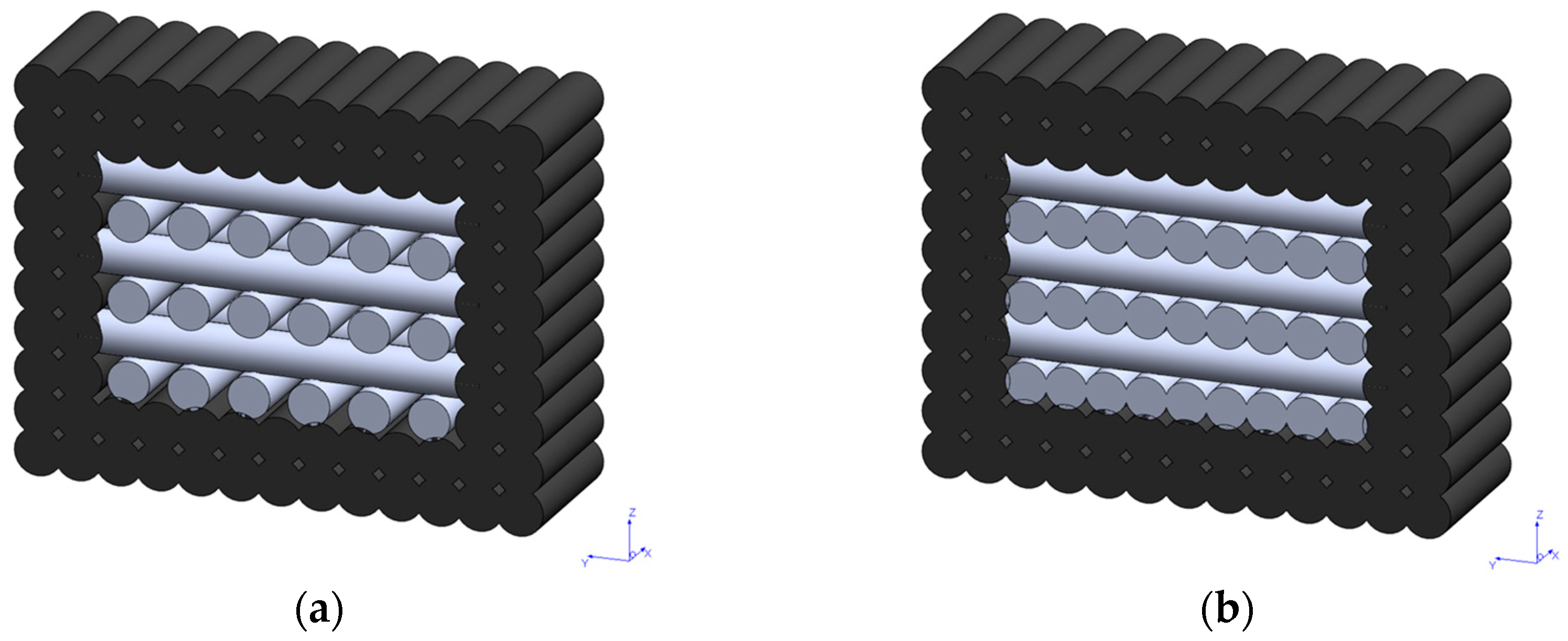
3.2.1. Comparative Analysis of Infill Volume Ratio
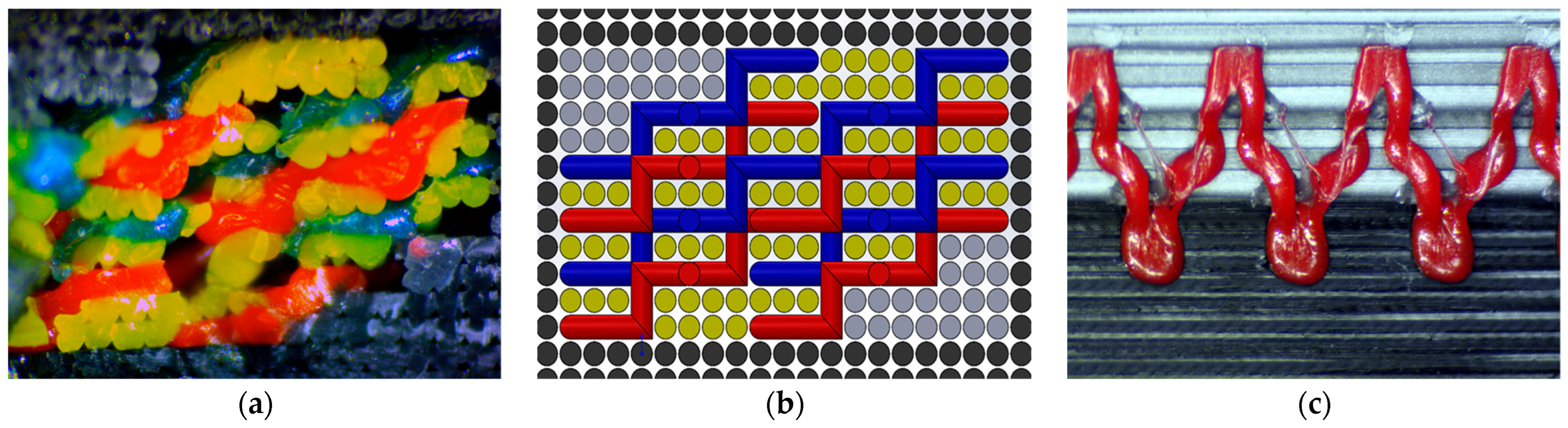
3.2.2. Multi-Color Sample Printing and Analysis
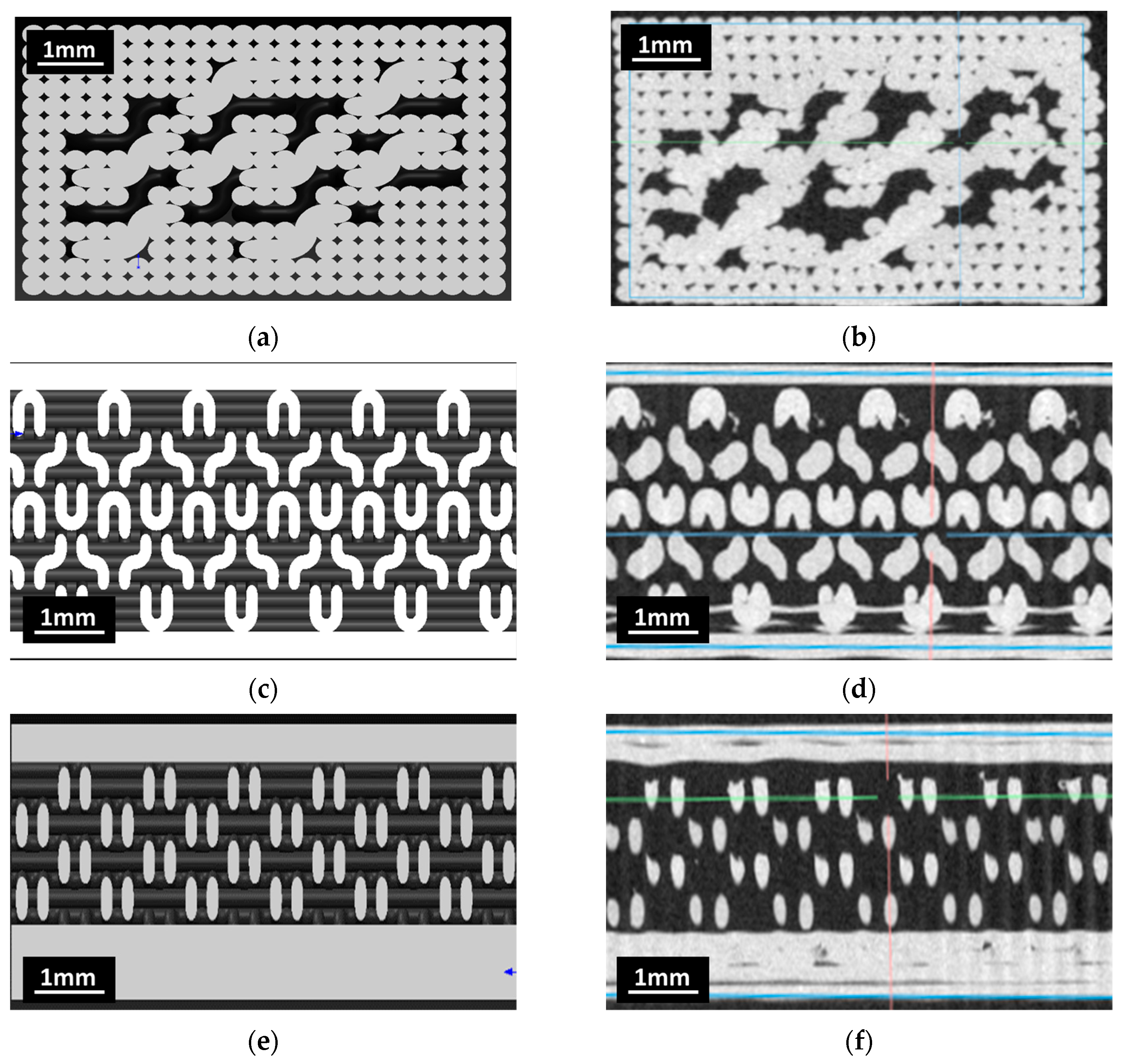
3.2.3. Microcomputed X-Ray Tomography
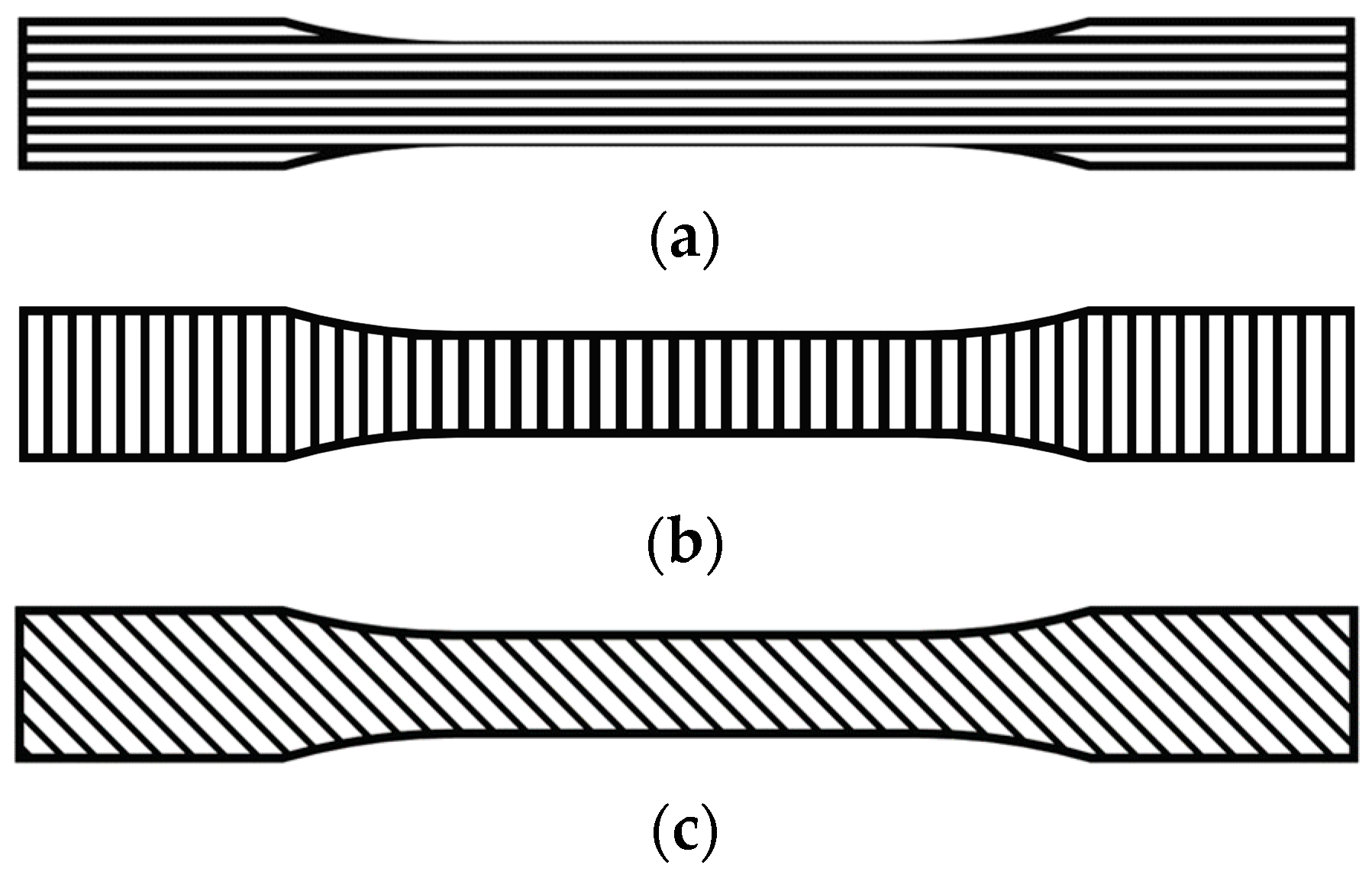
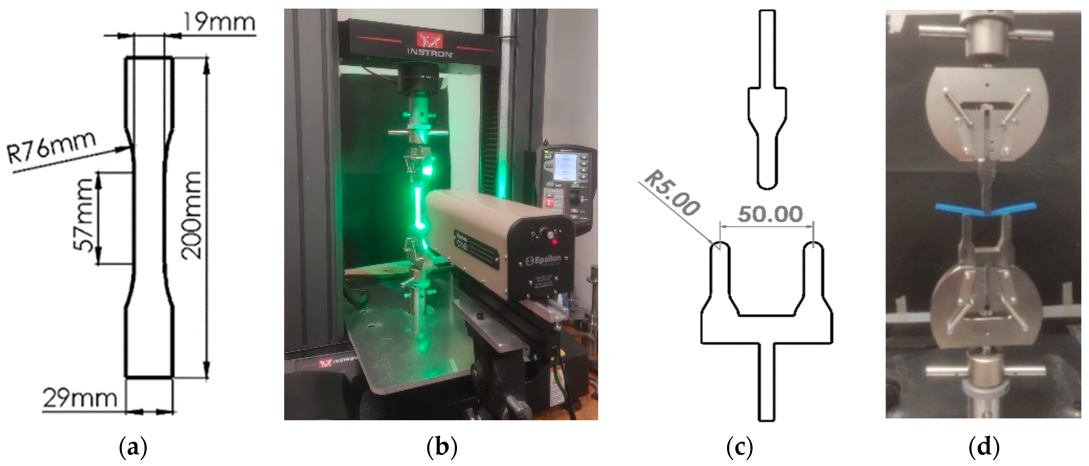
3.2.4. Mechanical Testing
4. Results and Discussion
4.1. Morphology of Z-Stitching Structures
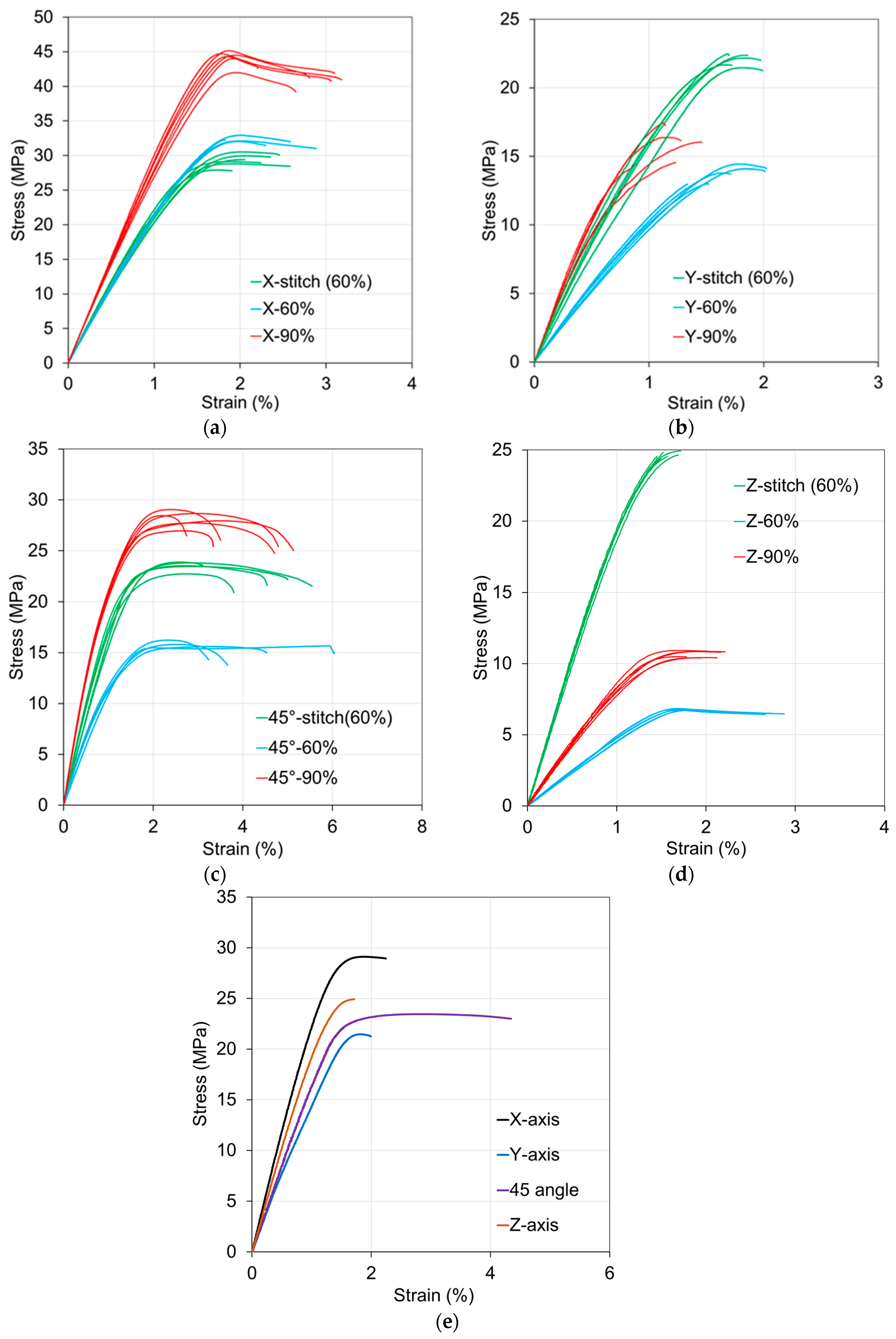
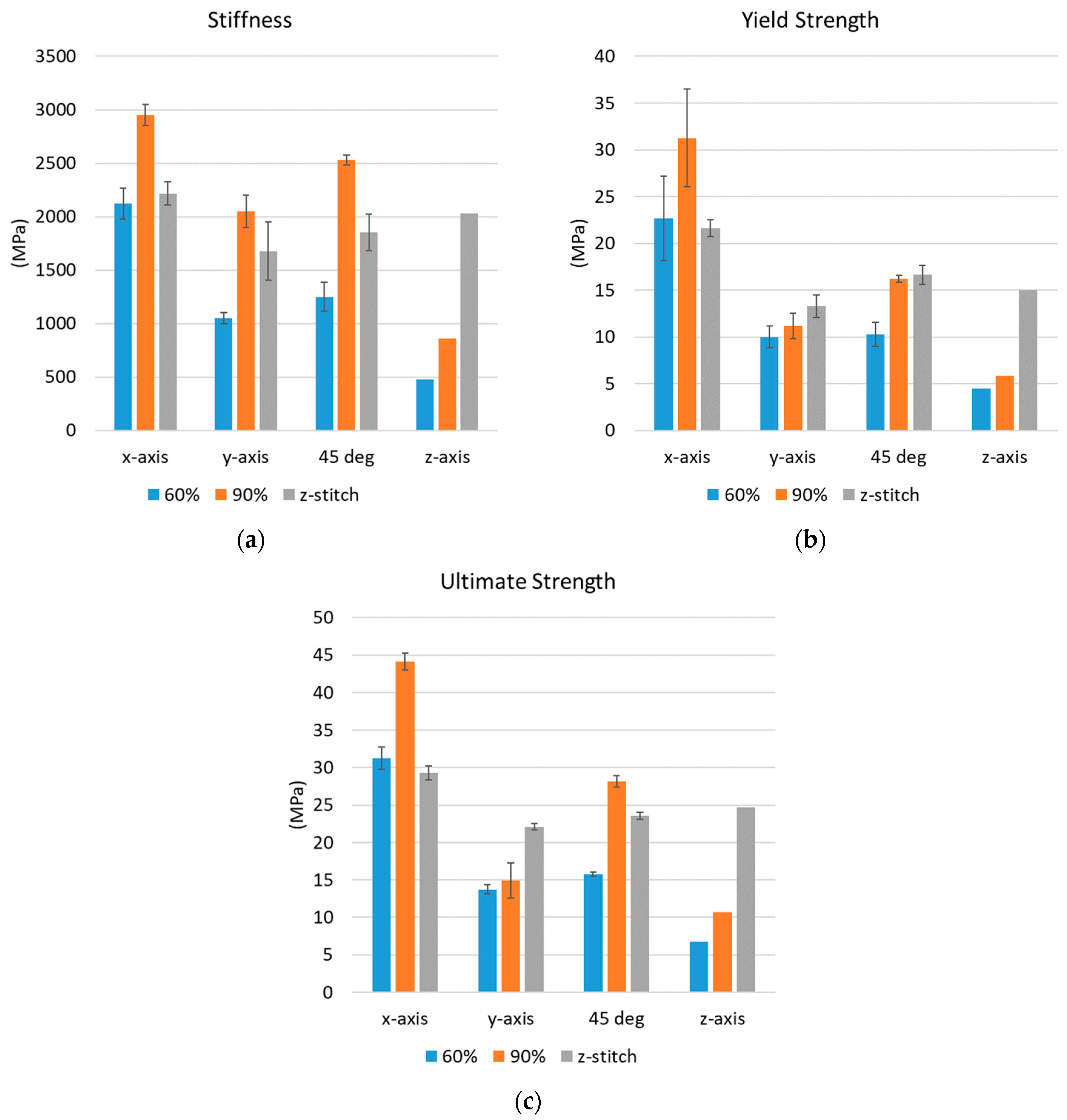
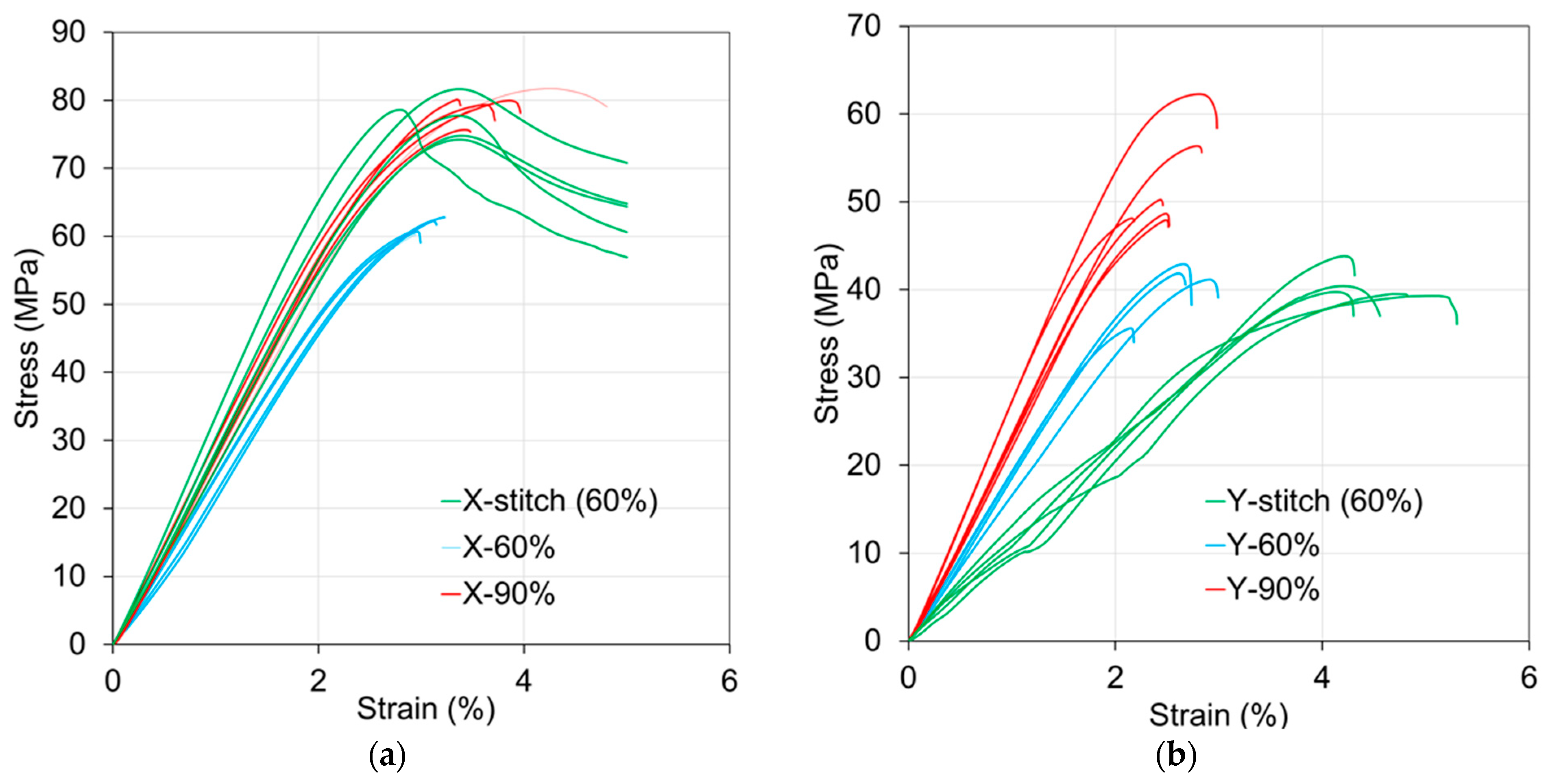
4.2. Tensile Testing
4.3. Three-Point Bending Tests
4.4. Fabrication Time Analysis
4.5. Limitations of the Z-Stitching Technique
5. Conclusions
Author Contributions
Funding
Data Availability Statement
Conflicts of Interest
References
- Wang, Y.; Liu, Z.; Gu, H.; Cui, C.; Hao, J. Improved Mechanical Properties of 3D-Printed SiC/PLA Composite Parts by Microwave Heating. J. Mater. Res. 2019, 34, 3412–3419. [Google Scholar] [CrossRef]
- Shanmugam, V.; Rajendran, D.J.J.; Babu, K.; Rajendran, S.; Veerasimman, A.; Marimuthu, U.; Singh, S.; Das, O.; Neisiany, R.E.; Hedenqvist, M.S.; et al. The Mechanical Testing and Performance Analysis of Polymer-Fibre Composites Prepared through the Additive Manufacturing. Polym. Test. 2021, 93, 106925. [Google Scholar] [CrossRef]
- Akhoundi, B.; Nabipour, M.; Hajami, F.; Band, S.S.; Mosavi, A. Calculating Filament Feed in the Fused Deposition Modeling Process to Correctly Print Continuous Fiber Composites in Curved Paths. Materials 2020, 13, 4480. [Google Scholar] [CrossRef]
- Wang, K.; Long, H.; Chen, Y.; Baniassadi, M.; Rao, Y.; Peng, Y. Heat-Treatment Effects on Dimensional Stability and Mechanical Properties of 3D Printed Continuous Carbon Fiber-Reinforced Composites. Compos. Part A Appl. Sci. Manuf. 2021, 147, 106460. [Google Scholar] [CrossRef]
- Shang, J.; Tian, X.; Luo, M.; Zhu, W.; Li, D.; Qin, Y.; Shan, Z. Controllable Inter-Line Bonding Performance and Fracture Patterns of Continuous Fiber Reinforced Composites by Sinusoidal-Path 3D Printing. Compos. Sci. Technol. 2020, 192, 108096. [Google Scholar] [CrossRef]
- Li, S.; Cheng, P.; Ahzi, S.; Peng, Y.; Wang, K.; Chinesta, F.; Correia, J.P.M. Advances in Hybrid Fibers Reinforced Polymer-Based Composites Prepared by FDM: A Review on Mechanical Properties and Prospects. Compos. Commun. 2023, 40, 101592. [Google Scholar] [CrossRef]
- Singh, D.; Rathore, S. A Review on FDM-Based 3D Printer Exploring the Capabilities and Limitations. In Recent Advances in Mechanical Engineering; Sanjay Yadav, Y., Shrivastava, S.R., Eds.; Springer: Singapore, 2024; pp. 463–473. [Google Scholar] [CrossRef]
- Iftekar, S.F.; Aabid, A.; Amir, A.; Baig, M. Advancements and Limitations in 3D Printing Materials and Technologies: A Critical Review. Polymer 2023, 15, 2519. [Google Scholar] [CrossRef]
- Penumakala, P.K.; Santo, J.; Thomas, A. A Critical Review on the Fused Deposition Modeling of Thermoplastic Polymer Composites. Compos. Part B Eng. 2020, 201, 108336. [Google Scholar] [CrossRef]
- Luo, M.; Tian, X.; Shang, J.; Yun, J.; Zhu, W.; Li, D.; Qin, Y. Bi-Scale Interfacial Bond Behaviors of CCF/PEEK Composites by Plasma-Laser Cooperatively Assisted 3D Printing Process. Compos. Part A Appl. Sci. Manuf. 2020, 131, 105812. [Google Scholar] [CrossRef]
- Sabyrov, N.; Abilgaziyev, A.; Ali, M.H. Enhancing Interlayer Bonding Strength of FDM 3D Printing Technology by Diode Laser-Assisted System. Int. J. Adv. Manuf. Technol. 2020, 108, 603–611. [Google Scholar] [CrossRef]
- Ming, Y.; Zhang, S.; Han, W.; Wang, B.; Duan, Y.; Xiao, H. Investigation on Process Parameters of 3D Printed Continuous Carbon Fiber-Reinforced Thermosetting Epoxy Composites. Addit. Manuf. 2020, 33, 101184. [Google Scholar] [CrossRef]
- Ahmadifar, M.; Benfriha, K.; Shirinbayan, M. Tcharkhtchi, Additive Manufacturing of Polymer-Based Composites Using Fused Filament Fabrication (FFF): A Review. Appl. Compos. Mater. 2021, 28, 1335–1380. [Google Scholar] [CrossRef]
- Awasthi, P.; Banerjee, S.S. Fused Deposition Modeling of Thermoplastic Elastomeric Materials: Challenges and Opportunities. Addit. Manuf. 2021, 46, 102177. [Google Scholar] [CrossRef]
- Naveen Kumar, C.; Venkatesan, S. A Review on the Fused Deposition Modelling of Fibre-Reinforced Polymer Composites: Influence of Process Parameters, Pre-Processing and Post Processing Techniques. Proc. Inst. Mech. Eng. Part L J. Mater. Des. Appl. 2024, 238, 2096–2119. [Google Scholar] [CrossRef]
- Bhushan, T.V.S.M.R.; Chandrasekhar, A.; Raju, B.; Rahul Puri, C. Influence of Printing Parameters to Optimize Mechanical Properties in Additive Manufacturing–A Review. J. Phys. Conf. Ser. 2024, 2837, 012090. [Google Scholar] [CrossRef]
- Shanmugam, V.; Babu, K.; Kannan, G.; Mensah, R.A.; Samantaray, S.K.; Das, O. The Thermal Properties of FDM Printed Polymeric Materials: A Review. Polym. Degrad. Stab. 2024, 228, 110902. [Google Scholar] [CrossRef]
- Allum, J.; Moetazedian, A.; Gleadall, A.; Mitchell, N.; Marinopoulos, T.; McAdam, I.; Li, S.; Silberschmidt, V.V. Extra-Wide Deposition in Extrusion Additive Manufacturing: A New Convention for Improved Interlayer Mechanical Performance. Addit. Manuf. 2023, 61, 103334. [Google Scholar] [CrossRef]
- Parmiggiani, A.; Prato, M.; Pizzorni, M. Effect of the Fiber Orientation on the Tensile and Flexural Behavior of Continuous Carbon Fiber Composites Made via Fused Filament Fabrication. Int. J. Adv. Manuf. Technol. 2021, 114, 2085–2101. [Google Scholar] [CrossRef]
- Nayyeri, P.; Zareinia, K.; Bougherara, H. Planar and Nonplanar Slicing Algorithms for Fused Deposition Modeling Technology: A Critical Review. Int. J. Adv. Manuf. Technol. 2022, 119, 2785–2810. [Google Scholar] [CrossRef]
- Nisja, G.A.; Cao, A.; Gao, C. Short Review of Nonplanar Fused Deposition Modeling Printing. Mater. Des. Process. Commun. 2021, 3, e221. [Google Scholar] [CrossRef]
- Allum, J.; Kitzinger, J.; Li, Y.; Silberschmidt, V.V.; Gleadall, A. ZigZagZ: Improving Mechanical Performance in Extrusion Additive Manufacturing by Nonplanar Toolpaths. Addit. Manuf. 2021, 38, 101715. [Google Scholar] [CrossRef]
- Duty, C.; Failla, J.; Kim, S.; Smith, T.; Lindahl, J.; Kunc, V. Z-Pinning Approach for 3D Printing Mechanically Isotropic Materials. Addit. Manuf. 2019, 27, 175–184. [Google Scholar] [CrossRef]
- McCaw, J.C.S.; Cuan-Urquizo, E. Curved-Layered Additive Manufacturing of Non-Planar, Parametric Lattice Structures. Mater. Des. 2018, 160, 949–963. [Google Scholar] [CrossRef]
- Fernandez-Vicente, M.; Calle, W.; Ferrandiz, S.; Conejero, A. Effect of Infill Parameters on Tensile Mechanical Behavior in Desktop 3D Printing. 3D Print. Addit. Manuf. 2016, 3, 183–192. [Google Scholar] [CrossRef]
- ASTM D638−22; Standard Test Method for Tensile Properties of Plastics. ASTM B. Stand.: West Conshohocken, PA, USA, 2022; Volume 08.01. [CrossRef]
- ASTM D790-17; Standard Test Methods for Flexural Properties of Unreinforced and Reinforced Plastics and Electrical Insulating Materials. ASTM B. Stand.: West Conshohocken, PA, USA, 2017; Volume 08.01. [CrossRef]
- Dave, H.K.; Patadiya, N.H.; Prajapati, A.R.; Rajpurohit, S.R. Effect of Infill Pattern and Infill Density at Varying Part Orientation on Tensile Properties of Fused Deposition Modeling-Printed Poly-Lactic Acid Part. Proc. Inst. Mech. Eng. Part C J. Mech. Eng. Sci. 2021, 235, 1811–1827. [Google Scholar] [CrossRef]
- Sriya Ambati, S.; Ambatipudi, R. Effect of Infill Density and Infill Pattern on the Mechanical Properties of 3D Printed PLA Parts. Mater. Today Proc. 2022, 64, 804–807. [Google Scholar] [CrossRef]
- Aitchison, A.; Wang, Q. Localised Pre-Heating to Improve Inter-Layer Delamination Strength in Fused Deposition Modelling. Proc. ASME Des. Eng. Tech. Conf. 2019, 59223, V004T05A008. [Google Scholar] [CrossRef]


| Parameter | Value and Unit |
|---|---|
| PLA filament diameter | 1.75 ± 0.02 mm |
| Nozzle diameter | 0.4 mm |
| Nozzle temperature | 220 °C |
| Bed temperature | 60 °C |
| Layer height | 0.3 mm |
| Printing speeds: | |
| ● Rapid motion | 60 mm/s |
| ● Contouring | 20 mm/s |
| ● Stitch support | 15 mm/s |
| ● Stitch | 10 mm/s |
| Loading Direction | Specimen Type | Stiffness (GPa) | Yield Strength (MPa) | Ultimate Strength (MPa) | |||
|---|---|---|---|---|---|---|---|
| Mean | SD | Mean | SD | Mean | SD | ||
| x-axis | 60% | 2.12 | 0.14 | 22.68 | 4.54 | 31.26 | 1.48 |
| 90% | 2.95 | 0.10 | 31.27 | 5.22 | 44.12 | 1.11 | |
| z-stitch | 2.22 | 0.11 | 21.64 | 0.92 | 29.29 | 0.91 | |
| y-axis | 60% | 1.05 | 0.05 | 10.02 | 1.16 | 13.73 | 0.6 |
| 90% | 2.05 | 0.15 | 11.19 | 1.38 | 14.93 | 2.35 | |
| z-stitch | 1.68 | 0.28 | 13.31 | 1.21 | 22.08 | 0.41 | |
| 45° | 60% | 1.25 | 0.14 | 10.26 | 1.27 | 15.74 | 0.27 |
| 90% | 2.53 | 0.05 | 16.22 | 0.38 | 28.14 | 0.75 | |
| z-stitch | 1.86 | 0.17 | 16.64 | 1.02 | 23.56 | 0.45 | |
| 60% | 0.47 | 0.13 | 4.52 | 0.68 | 6.77 | 0.05 | |
| z-axis | 90% | 0.86 | 0.23 | 5.85 | 0.34 | 10.65 | 0.24 |
| z-stitch | 2.02 | 0.54 | 14.99 | 1.55 | 24.65 | 0.2 | |
| Material | Infill Type and Density | UTS in Raster Direction (MPa) | UTS Transverse to Raster Direction (MPa) | Isotropy Ratio (/) | Reference |
|---|---|---|---|---|---|
| PLA | Rectilinear 60% | 25.6 | 17.4 | 0.67 | [28] |
| PLA | Concentric 60% | 28.2 | 18.3 | 0.64 | [28] |
| PLA | Hilbert curve 60% | 10 | 8.5 | 0.85 | [28] |
| PLA | Grid 60% | 25.2 | [29] | ||
| PLA | Triangle 60% | 23.4 | [29] | ||
| PLA | Gyroid 60% | 24.5 | [29] | ||
| PLA | Rectilinear 60% | 31.3 | 13.7 | 0.44 | present |
| PLA | Z-stitch 60% | 29.3 | 22.8 | 0.78 | present |
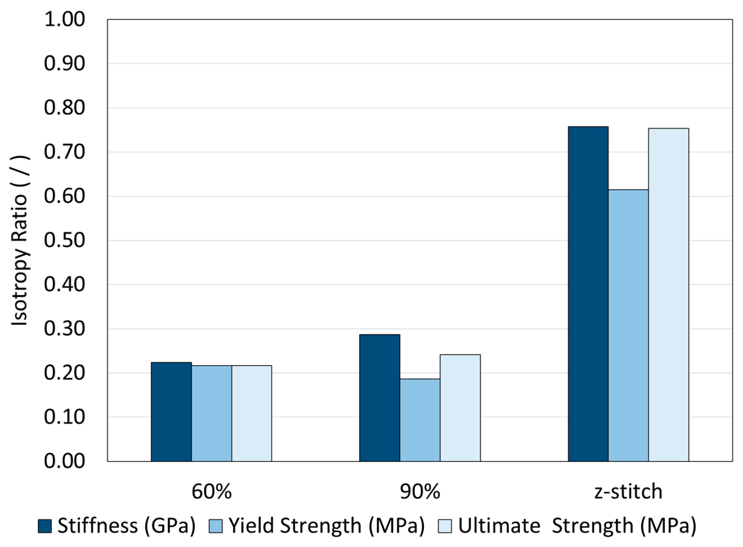
| Specimen Type | Isotropy Ratio with Respect to Stiffness (/) | Isotropy Ratio with Respect to Yield Strength (/) | Isotropy Ratio with Respect to Ultimate Strength (/) |
|---|---|---|---|
| Rectilinear 90% | 0.29 | 0.19 | 0.24 |
| Rectilinear 60% | 0.22 | 0.22 | 0.22 |
| Z-stitch 60% | 0.76 | 0.62 | 0.75 |
Disclaimer/Publisher’s Note: The statements, opinions and data contained in all publications are solely those of the individual author(s) and contributor(s) and not of MDPI and/or the editor(s). MDPI and/or the editor(s) disclaim responsibility for any injury to people or property resulting from any ideas, methods, instructions or products referred to in the content. |
© 2025 by the authors. Licensee MDPI, Basel, Switzerland. This article is an open access article distributed under the terms and conditions of the Creative Commons Attribution (CC BY) license (https://creativecommons.org/licenses/by/4.0/).
Share and Cite
Elsherbiny, A.; Mohiuddin, A.; Dehgahi, S.; Mertiny, P.; Qureshi, A.J. Z-Stitching Technique for Improved Mechanical Performance in Fused Filament Fabrication. J. Manuf. Mater. Process. 2025, 9, 97. https://doi.org/10.3390/jmmp9030097
Elsherbiny A, Mohiuddin A, Dehgahi S, Mertiny P, Qureshi AJ. Z-Stitching Technique for Improved Mechanical Performance in Fused Filament Fabrication. Journal of Manufacturing and Materials Processing. 2025; 9(3):97. https://doi.org/10.3390/jmmp9030097
Chicago/Turabian StyleElsherbiny, Ahmed, Abdullah Mohiuddin, Shirin Dehgahi, Pierre Mertiny, and Ahmed Jawad Qureshi. 2025. "Z-Stitching Technique for Improved Mechanical Performance in Fused Filament Fabrication" Journal of Manufacturing and Materials Processing 9, no. 3: 97. https://doi.org/10.3390/jmmp9030097
APA StyleElsherbiny, A., Mohiuddin, A., Dehgahi, S., Mertiny, P., & Qureshi, A. J. (2025). Z-Stitching Technique for Improved Mechanical Performance in Fused Filament Fabrication. Journal of Manufacturing and Materials Processing, 9(3), 97. https://doi.org/10.3390/jmmp9030097