Article

Prediction of Residual Stresses During the Hot Forging Process of Spherical Shells Based on Microstructural Evolution

by
Yupeng Wu
1,
Jiasheng Li
2,*,
Zhaocheng Wei
1,
Yuxin Fang
1,2,
Hongxia Li
1 and
Ming Huang
2,*
1
Institute of Mechanical Engineering, Dalian University of Technology, Dalian 116024, China
2
Institute of Mechanical Manufacturing Technology, China Academy of Engineering Physics, Mianyang 621900, China
*
Authors to whom correspondence should be addressed.
J. Manuf. Mater. Process. 2025, 9(3), 86; https://doi.org/10.3390/jmmp9030086
Submission received: 3 January 2025 / Revised: 19 February 2025 / Accepted: 19 February 2025 / Published: 10 March 2025

Abstract

A unified viscoplastic constitutive model based on internal physical variables was proposed to predict the viscoplastic mechanical behavior and microstructure evolution of metals during hot forging. Based on the phase transformation theory of materials under the effect of temperature, the evolution mechanism of residual stress during the cooling process after hot forging and stamping was explored. The determined unified viscoplastic constitutive equation was written in the VUMAT subroutine and employed for the explicit FE analysis of the hot forging and stamping process of thin-walled spherical shells. In the data transfer process, the stress field, temperature field, and deformation characteristics calculated during the high-temperature transient of the hot forging and stamping process were inherited. Meanwhile, the thermoplastic constitutive equation considering the influence of phase transformation was written in the UMAT subroutine and utilized for the implicit FE analysis of the cooling process of thin-walled spherical shells. Through comparison with the measured stress results of the spherical shells after actual forging, it was shown that the proposed constitutive model can effectively predict the microstructural evolution and the final residual stress distribution pattern of medium-carbon steel during the hot forging process.

1. Introduction

Large thin-walled precision spherical shells are widely employed in aerospace, strategic weaponry, and various other domains. The diameter of the final product of the thin-walled spherical shell is about 200 mm, the wall thickness is about 2 mm, and the contour accuracy is required to be within 10 μm. Due to their substantial diameter-to-thickness ratio (approaching 100:1) and overall low rigidity, residual stress becomes a critical factor that influences machining accuracy and service stability. Given the limitations of current methods for measuring residual stress, obtaining a comprehensive assessment of the residual stress distribution throughout the entire component—particularly within its interior—remains challenging. Consequently, the finite element simulation method has been utilized to characterize the evolution of stress during the manufacturing process in real time and from a holistic perspective. This approach aims to provide theoretical guidance for managing residual stress and developing effective processing strategies.
The material examined in this study is medium-carbon steel (ISO:C45E [1]), which is widely employed in the fabrication of components due to its high strength, good toughness, and excellent machinability [1]. The softening mechanism of metallic materials is highly sensitive to thermal processing parameters [2]; therefore, optimal processing properties can be achieved by controlling these parameters to enhance microstructural evolution [3]. To improve the processing performance of the material, a series of extrusion rounding treatments are conducted at elevated temperatures to transform the bar shape into a disc-shaped piece. This disc-shaped piece serves as the initial blank for the hot forging stamping process. Prior to forging, it is crucial to heat the material above 1050 °C and maintain it at that temperature for a specified duration to ensure complete austenitization, thereby facilitating superior plasticity during subsequent processes [4].
Thermoplasticity intrinsic models are adept at characterizing the flow stress curves of materials subjected to elevated temperatures. When integrated with finite element simulation techniques, these models can effectively predict the thermoplastic deformation processes across a variety of materials. Numerous studies have concentrated on elucidating the flow behavior of materials through the application of the Johnson–Cook model [5] and the Arrhenius model [6]. However, traditional image-only intrinsic models typically utilize macroscopic parameters such as temperature, strain, and strain rate as their variables. These phenomenological models summarize experimental data and employ direct fitting methods to derive their formulations. While this approach offers a reasonable representation of deformation behavior under fixed conditions, it often overlooks an examination of the fundamental nature of material deformation—particularly for those materials that are sensitive to thermal processing history—which can result in significant discrepancies between predicted and experimental outcomes [7]. In contrast, physically based internal state variable (ISV) models provide a more accurate depiction of the coupling mechanisms between microstructure evolution and stress evolution while facilitating predictions within a finite element framework. Huo et al. utilized an ISV model to investigate the wedge transverse rolling of 25CrMo4 steel, aiming to predict grain size and recrystallization volume fraction [8]. Alabort et al. developed an ISV model for Ti6Al4V alloy, focusing on the examination of changes in grain size, void ratio, and dislocation density during superplastic forming processes [9]. Cai et al. established a phase field model that integrates grain growth, recrystallization, and second-phase pinning effects under hot deformation conditions for AZ80 magnesium alloy; this model effectively correlates dislocation evolution with the realization of grain boundary transitions while maintaining practical physical significance across macro- and micro-time scales [10]. The authors Su et al. established a viscoplastic constitutive model for the AZ80 magnesium alloy, which incorporates mechanisms of coupled dislocation proliferation and recovery, recrystallization nucleation, and grain boundary migration. This model demonstrates high predictive accuracy regarding the macroscopic mechanical response characterized by dynamic recrystallization softening features and microstructural evolution [11]. Yang et al. developed a viscoplastic constitutive model for the 718 chromium–nickel–iron alloy that accounts for the effects of dislocation density, recrystallization, grain size, and δ-phase evolution on superplastic flow behavior. By describing changes in particle average radius and volume fraction, this model reflects the role of precipitates as pinning points in facilitating dislocation diffusion while restricting grain boundary slip and grain growth [12]. Pan et al. employed an ISV model to simulate variations in grain size and dynamic recrystallization during the spinning process of ZK61 magnesium alloy thin-walled tubes [13]. Extensive research by numerous scholars has validated the accuracy of the ISV model. Given that stress evolution within components during thermoplastic processing is challenging to measure directly, applying a physics-based ISV model within finite element simulations serves as an effective approach to predict microstructural evolution during hot forging processes of large thin-walled components as well as residual stress distribution patterns under high-temperature transients.
However, during the cooling process, the residual stress in components undergoes significant changes, and monitoring of this residual stress can only be conducted in the post-cooling state. Therefore, it is essential to investigate the mechanism of stress evolution during the cooling process following thermal forging and stamping of spherical shells. Traditional finite element simulation methods are limited to reflecting material sensitivity to temperature within the range of thermal expansion and contraction; they fail to reveal the importance of microstructural phase change on stress behavior [14]. Consequently, based on phase transformation theory, it is necessary to consider phase transformation kinetics during cooling. By calculating the volume fractions of various phases at different temporal and spatial states, we can convert macroscopic thermodynamic properties into a product of thermodynamic properties associated with each phase’s organization and its corresponding volume fraction, thereby aligning with actual physical laws. Zhu et al. examined the effects of phase transformation plasticity and martensitic expansion in their study on austenitization dynamics during quenching processes for high-strength steel [15]. Zhong et al. established a coupling model involving phase transformations as well as temperature and stress–strain relationships within 42CrMo steel; they quantitatively analyzed phenomena such as phase transitions, latent heat release, and plasticity occurring during quenching through experimental validation to predict relevant material properties [16]. Furthermore, Wang et al. formulated kinetic equations addressing martensite decomposition alongside residual austenite during tempering processes for Mn-Mo-Ni steels [17]. Li et al. conducted multi-field coupling simulations regarding temperature–structure–performance interactions throughout heat treatment processes (quenching) for SA508Gr.3 steel forgings while optimizing heating protocols [18]. Based on current research findings by scholars in this field, incorporating phase transition theory into thermodynamic simulations effectively elucidates how temperature influences residual stress evolution patterns.
The present study conducts high-temperature dynamic compression experiments on the pre-formed blanks prior to hot forging and stamping. The experimental data obtained under varying temperature and strain rate conditions reveal the corresponding grain sizes, dislocation densities, and recrystallization volume fractions at different strains. A unified viscoplastic constitutive model for the material was proposed based on these findings. Utilizing phase transformation theory and referencing the TTT curve of undercooled austenite in medium-carbon steel, this research elucidates the evolution patterns of various phases during air cooling processes. Consequently, a thermoplastic constitutive model that accounts for phase transformations has been developed. By comparing with actual residual stress measurement results from thin-walled spherical shells post-forging, it was demonstrated that the proposed constitutive model accurately predicts microstructural evolution and changes in residual stress throughout the forging process. This provides theoretical guidance for residual stress control and optimization of processing parameters.

2. Experimental Procedure

The Gleeble-3500 thermal simulation testing machine (ZhongKeKeFu Company in Beijing, China) was employed to conduct high-temperature uniaxial compression tests on specimens of medium-carbon steel used for thin-walled spherical shells. This study aims to investigate the viscoplastic flow stress and microstructural evolution of the material under elevated temperature conditions. The chemical composition of this steel is detailed in Table 1.
The as-forged disc-shaped blanks were subjected to wire cutting to produce cylindrical samples with a diameter of 8 mm and a length of 15 mm. Under isothermal conditions, grain refinement experiments were conducted, following the specific experimental procedure illustrated in Figure 1. Each sample was heated at a rate of 10 °C/s to a temperature of 1000 °C and held at this temperature for 3 min to ensure complete crystallization. Subsequently, the samples were further heated to one of the deformation temperatures: 1050 °C, 1100 °C, 1150 °C, or 1200 °C. At the selected deformation temperature, they were compressed at strain rates of either 0.1 s⁻1 or 1 s⁻1 until reaching one of the true strain values: 0, 0.2, 0.4, 0.6, or 0.8. Following compression, immediate water quenching was performed to preserve microstructural stability.
The samples subjected to high-temperature compression followed by in situ cooling were axially sliced. Different grits of sandpaper (400, 600, 1000, 1500, and 2500) were employed for grinding, followed by electro-polishing treatment. Subsequently, the microstructure was characterized using a metallurgical microscope and electron backscatter diffraction (EBSD) scanning electron microscopy. Some of the microstructural features are illustrated in Figure 2. The grain size was measured using OIM 7.3 software, with the average grain sizes from the grain refinement tests presented in Table 2.

3. Unified Viscoplastic Constitutive Model

3.1. The Establishment of the Unified Viscoplastic Constitutive Model

The hyperbolic sine law demonstrates a capacity to adapt to a wider range of temperatures and strain rates when modeling the viscoplastic flow of metals [19]. This law is instrumental in elucidating the coupling mechanisms between microstructure and mechanical properties during the hot forging and stamping processes of medium-carbon steel.
σ = E ε T ε P
ε ˙ p = A 1 sinh A 2 σ R K d / d 0 γ 1
R ˙ = 0.5 B ρ ¯ 0.5 ρ ¯ ˙
ρ ¯ ˙ = A 4 d / d 0 δ 1 1 ρ ¯ ε ˙ P δ 2 C r ρ ¯ δ 3 A 3 ρ ¯ / 1 S δ 4 S ˙
S ˙ = Q 0 χ ρ ¯ ρ ¯ C 1 S 1 S λ 1
χ ˙ = H 1 1 χ ρ ¯
d ˙ = G 1 d 1 / d ψ 1 G 2 S ˙ d / d 0 ψ 2
In this context, σ denotes the flow stress, E represents the elastic modulus, and εT and εP correspond to the total strain and plastic strain, respectively. R signifies the isotropic hardening variable, K indicates the initial yield stress, d refers to the average grain size, and d0 represents the initial grain size. The term ρ ¯ denotes the normalized dislocation density and can be simplified as ρ ¯ = 1 ρ 0 / ρ [20], where ρ0 and ρ are the initial and deformed dislocation densities, respectively; thus, the value of ρ ¯ ranges from 0 to 1. S indicates the volume fraction of dynamically recrystallized grains, while χ represents the incubation period prior to recrystallization. Furthermore, E, A1, K, B, ρ ¯ C , Cr, H1 and G1 are temperature-dependent material parameters as shown in Table 3. Additionally, E0, A10, K10, B0, ρ ¯ C 0 , Cr0, H10, G10, γ1, λ1, d0, d1, G2, ψ1, ψ2 along with A2 through A4 (including δ1 through δ4) and Q0 through Q8 represent material constants that require optimization via genetic algorithms.

3.2. Multi-Parameter Optimization of the Viscoplastic Constitutive Equation Based on a Genetic Algorithm

The established unified viscoplastic constitutive equation set for medium-carbon steel comprises 31 material constants, which can effectively describe the flow stress and average grain size characteristics of medium-carbon steel under various deformation conditions. The equations exhibit interdependent relationships, resulting in a complex solution process. Therefore, it is necessary to employ an evolutionary search method to determine the optimal values within the equations, thereby minimizing the discrepancy between model predictions and experimental results and optimizing model parameters. To improve the stability and reliability of the analysis, a multi-objective optimization approach is utilized to precisely fit the experimental data for grain size-strain and stress–strain relationships. In this study, a Genetic Algorithm (GA) was utilized with a population size set at 200 and an iteration count of 500. Additionally, 10 cycles of optimization were conducted to obtain the optimal solution; detailed optimization parameters are presented in Table 4.
After substituting the optimized parameters into the unified viscoplastic constitutive equation, we compared the predicted values of flow stress and average grain size with experimental results under different deformation temperatures and strain rates, as shown in Figure 3. The analysis indicates that this model demonstrates a satisfactory predictive capability for medium-carbon steel across various deformation conditions. An increase in strain rate leads to a rise in dislocation density, which subsequently induces work hardening; conversely, an elevation in temperature can result in softening phenomena, while dynamic recrystallization may also contribute to flow softening. All these phenomena can be effectively described by the established unified constitutive equation.

4. Thermoplastic Constitutive Model of Phase Transformation

4.1. Phase Transition Field

According to research conducted by scholars, steel undergoes a phase transformation from ferrite matrix to austenite during the heating process. Conversely, during cooling, austenite transforms into ferrite, bainite, or martensite. Therefore, the kinetics of the phase transformation of undercooled austenite in medium-carbon steel can be expressed as follows [21]:
f A + f F + f P + f B + f M = 1
f m = f m a x 1 e x p b m t m * + t n m
t m * = 1 b m l n 1 f m 1 1 n m
b m i = ln 1 f 1 i t 1 n m i
n m i = ln ln 1 f 1 i ln 1 f 2 i ln t 1 t 2
f M = f M m a x 1 e x p β M s T
In this formula, fA represents the volume fraction of austenite, fF denotes the volume fraction of ferrite, fP denotes the volume fraction of pearlite, fB indicates the volume fraction of bainite, and fM signifies the volume fraction of martensite. Given that pearlite is a composite microstructure consisting of ferrite and cementite, its thermodynamic properties closely resemble those of ferrite. Therefore, ferrite is utilized as a substitute for pearlite in the subsequent phase transformation modeling. During the m-th time step, the phase transformation’s volume fraction is denoted as fm, while the time required for phase transformation is represented by tm*. The parameter fmax corresponds to the maximum phase transformation volume fraction, with parameters bm and nm relating to kinetic coefficients during this time interval. The magnitudes of these parameters are closely associated with transformation temperature, duration of phase change, and type of transformation; they can be determined using TTT curves that correspond to two isothermal times t1 and t2 at a specific temperature T, which relate to their respective transformed volumes f1 and f2. Furthermore, fMmax refers to the maximum volume fraction of martensite, while MS denotes the start temperature for martensitic transformation. Lastly, β represents the kinetic coefficient for martensitic phase transition.

4.2. Strain Field

In this model, the total thermoelastic-plastic constitutive equation is employed for the calculation of stress and strain, expressed as follows:
d ε = d ε e + d ε p + d ε t h + d ε t r + d ε t p
ε t h = i f i α i T
ε t r = i f i ε i t r
d ε i j t p = 3 K 1 f S i j d f
In this context, εe represents elastic strain, εp denotes plastic strain, εth refers to thermal strain, εtr indicates phase transformation elastic strain, and εtp signifies phase transformation plastic strain. Thermal strain arises from the volume changes associated with temperature variations and is considered isotropic. In the equation, fi represents the volume fraction of phase i, αi corresponds to the thermal expansion coefficient of phase i, and ∆T denotes the difference between the current temperature T and a selected reference temperature Tref. Phase transformation strain occurs due to material phase transitions and is also treated as isotropic; specifically, εitr accounts for the volumetric expansion associated with each generated microstructure during these transformations. For phase transformation plasticity, we employ a modified Leblond model based on G-J mechanisms to calculate the phase transformation plastic strains occurring during the austenite–martensite transition process; this aspect is regarded as anisotropic.

5. Distribution Law of Residual Stress in Thermal Forging of Thin-Walled Spherical Shells and Experimental Verification

5.1. Numerical Simulation of Residual Stress Evolution During the Hot Forging Process

The simulation of the hot forging process for thin-walled spherical shells is divided into two stages: hot forging stamping and air cooling. This analysis is conducted using the commercial finite element software Abaqus 2023, as illustrated in Figure 4.
During the hot forging stage, a unified viscoplastic constitutive equation for materials is implemented in the VUMAT subroutine format to elucidate the mechanical properties associated with microstructural evolution during high-temperature stamping processes. The air cooling phase incorporates a thermoplastic constitutive equation that accounts for phase transformations, described through coupled USDFLD, UEXPAN, UMAT, and HETVAL subroutines. This approach reveals the comprehensive effects of temperature-induced thermal strains, microstructural changes leading to phase transformation strains, and phase transformation plastic strains on stress evolution. The disc-shaped blank has a diameter of 354 mm and a thickness of 25 mm. The semi-spherical stamping die features a diameter of 190 mm, while the internal diameter of the concave die is 242 mm. The finite element model employs C3D8RT elements, with hourglass control implemented and the blank model is discretized with seven layers of elements along the thickness direction to ensure numerical stability. For material parameters relevant to the hot forging stamping process, please refer to Table 4 and Table 5; detailed material parameters related to the air cooling process can be found in Table 6, Table 7, Table 8, Table 9, Table 10 and Table 11, with data references to Mahmoud Y.’s work [22].
In the process of hot forging and stamping under high-temperature transient conditions, the overall radial, circumferential, and axial stresses are relatively low and exhibit a uniform distribution, as illustrated in Figure 5a–c. The grain size ranges from 23.3 to 25.5 μm, while the normalized dislocation density varies between 0.00012 and 0.00055. Additionally, the maximum recrystallization volume fraction is observed to be 5.89%.
The cooling process following stamping is conducted using air cooling. After cooling, residual compressive stresses are observed on the surface of the spherical shell in the radial direction, while residual tensile stresses manifest internally, as illustrated in Figure 6b. Furthermore, significant residual stresses are also present in both the circumferential and axial directions, as shown in Figure 6c,d, respectively. The primary product of the undercooled austenite phase transformation in the material is ferrite, as depicted in Figure 7a. On the end face of the spherical shell, some presence of bainite has been observed (Figure 7c), along with martensite (Figure 7d). Additionally, a very small amount of untransformed austenite has been identified (Figure 7b).

5.2. Measurement of Residual Stress Using Ultrasonic Method

To verify the accuracy of the residual stress simulation results for the hot forging and stamping process, ultrasonic methods were employed to measure the residual stress in the forged spherical shell. During the measurement process, the microstructure characteristics of the spherical shell materials are assumed to be uniform, supported by their isotropic properties and consistent manufacturing conditions. Three measurement paths were selected within one-fourth of the spherical shell’s area, with measurements taken along both circumferential and meridional directions, followed by averaging their values. Specifically, nine measurement points were established in the circumferential direction, while six measurement points were set in the meridional direction. The procedure for measuring residual stress in thin-walled spherical shells is illustrated in Figure 8.
The measurement results are highly consistent with the average stress values extracted from the corresponding regions in the simulation. The maximum discrepancy between the simulated and measured circumferential stress is 16.5%, while for axial stress, the maximum discrepancy is 12.8% (as shown in Figure 9). The primary source of error is likely attributed to variations in the material’s microstructure, including dislocations, grain boundaries, and defects. These microstructural heterogeneities lead to inconsistencies in the material’s acoustic time difference coefficient, ultimately reducing the accuracy of ultrasonic measurements. This indicates that the established unified viscoplastic constitutive model, along with the thermoplastic constitutive model that considers phase transformation, plays a significant guiding role in studying the evolution of stress during hot processing of medium-carbon steel.

6. Conclusions

This study presents a comprehensive investigation into the thermoelastic-plastic behavior of materials through the integration of a unified viscoplastic constitutive model and phase transformation theory. The reliability of this approach was systematically validated by comparative analysis between ultrasonic stress measurements and numerical simulation results. Furthermore, the research elucidates the evolution mechanisms of residual stresses during the hot forging process of medium-carbon steel. The principal findings can be summarized as follows:
(1)
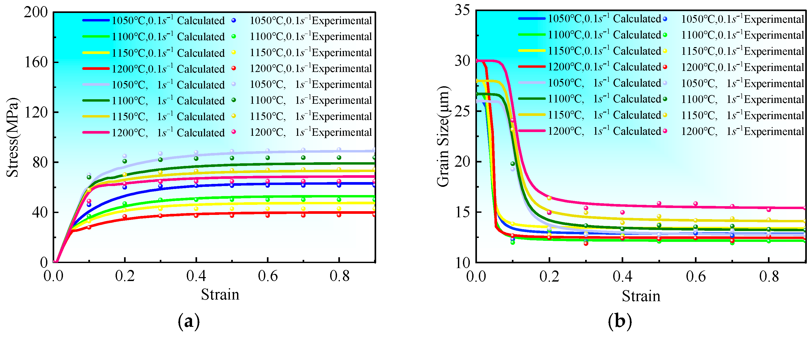
Through systematic high-temperature dynamic compression experiments, this study develops a unified viscoplastic constitutive model specifically tailored for medium-carbon steel. The proposed model effectively captures the intricate coupling mechanisms between microstructural evolution and stress–strain response across a wide range of thermomechanical processing conditions (temperature: 1050–1150 °C; strain rate: 0.1–1 s ⁻1). The model’s formulation incorporates key metallurgical phenomena, including dynamic recovery and recrystallization processes, enabling accurate prediction of material behavior under complex thermo-mechanical loading scenarios.
(2)
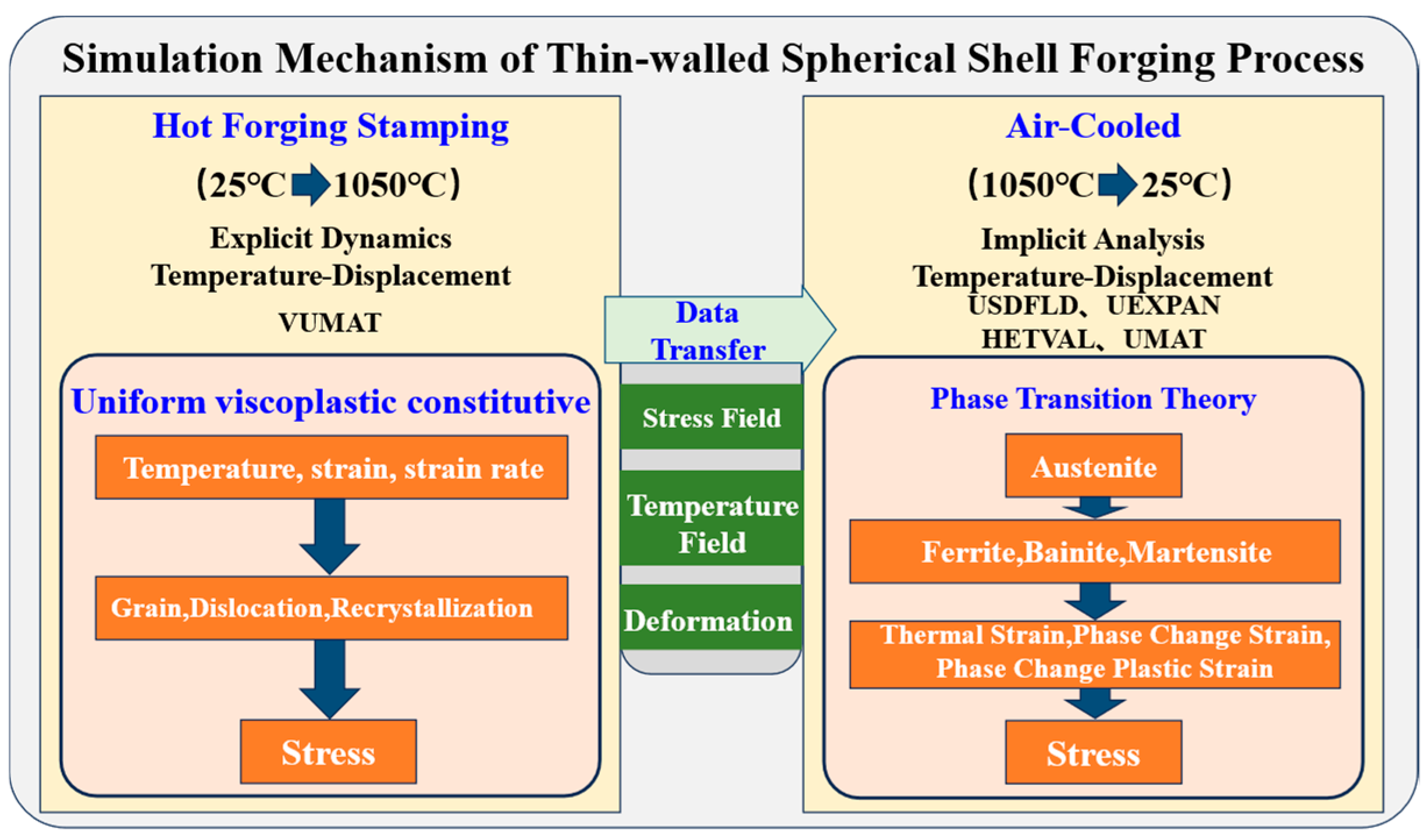
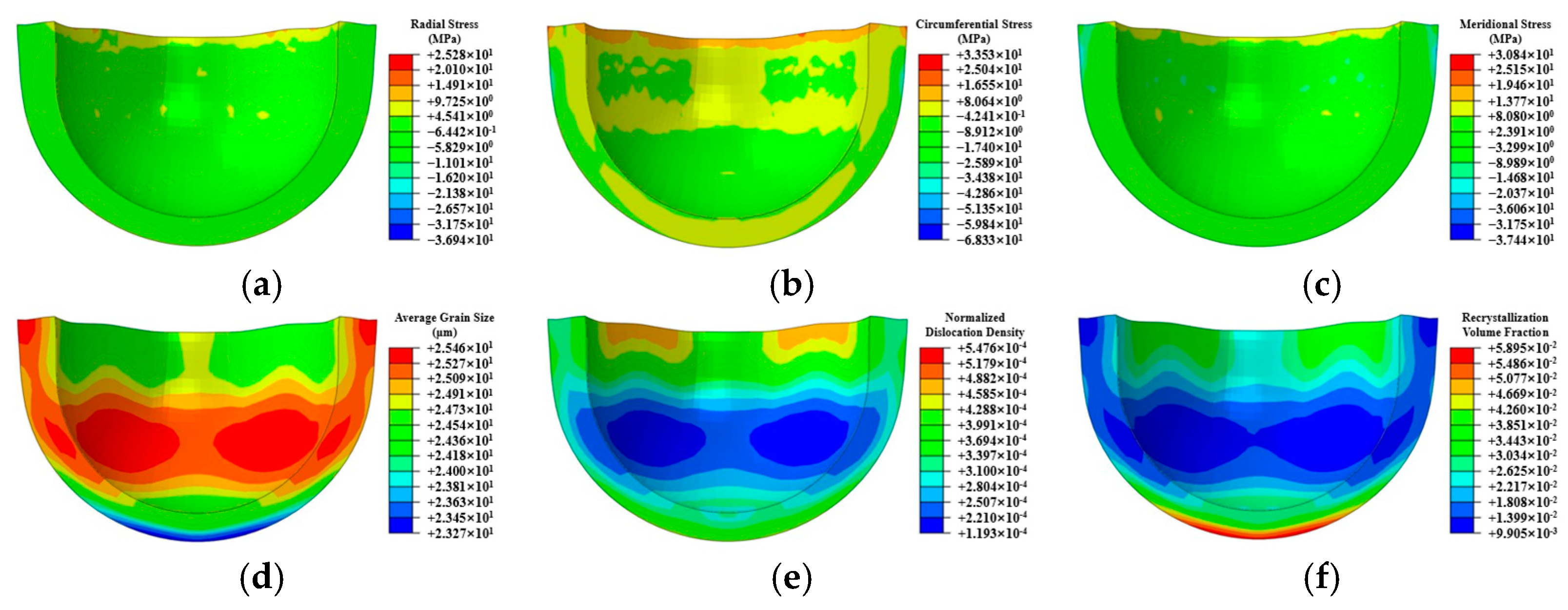
A unified viscoplastic constitutive model was employed to numerically simulate the behavior of thin-walled spherical shells during the hot forging and stamping process. The study revealed the distribution patterns of grain size, dislocations, and recrystallization under high-temperature transient conditions. Corresponding processing techniques were developed to ensure that components achieve a uniform grain distribution.
(3)
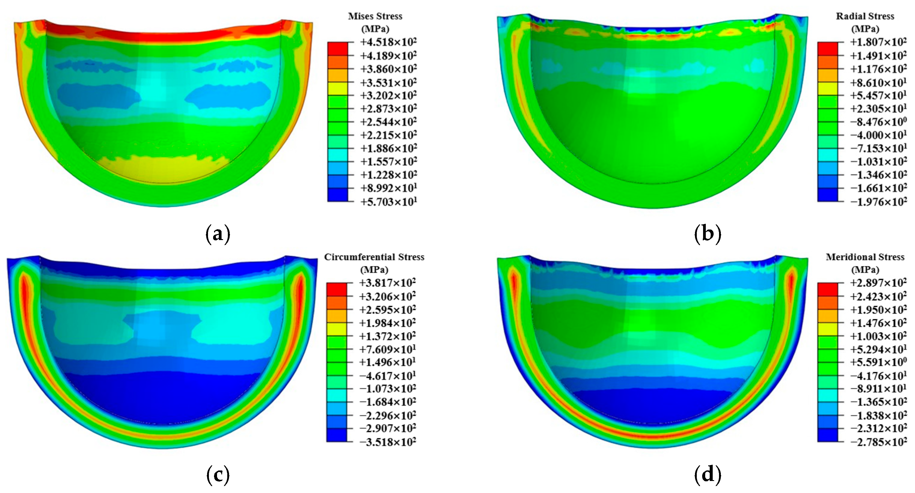
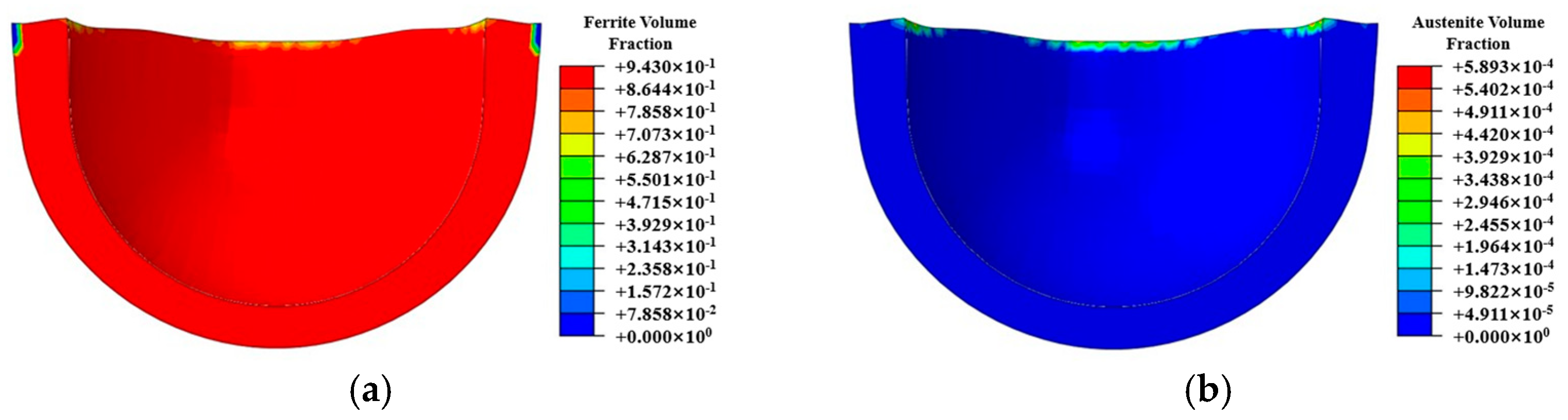
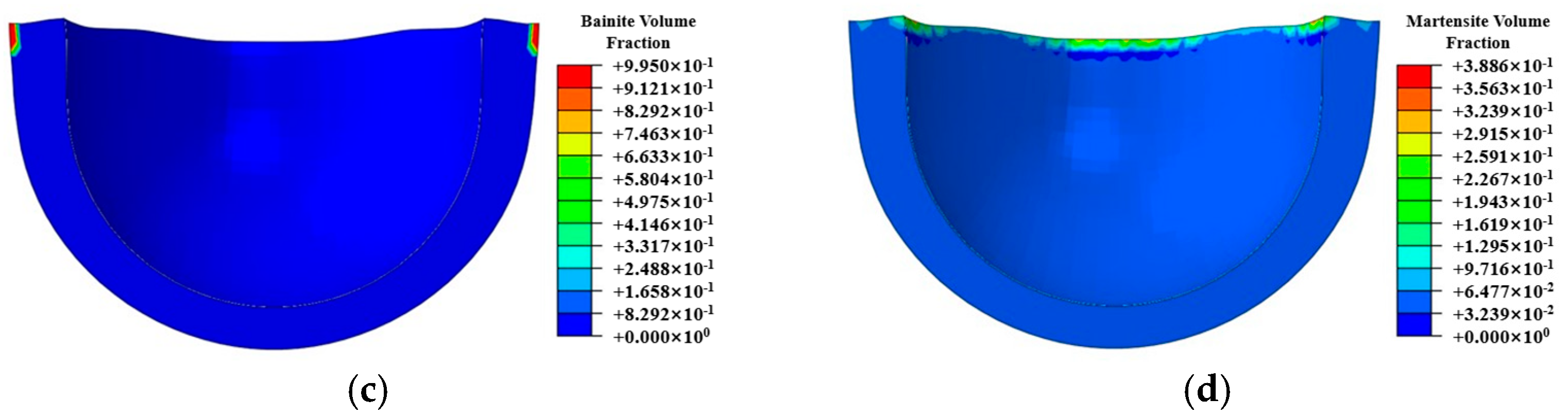
Leveraging the time–temperature–transformation (TTT) diagram for undercooled austenite in medium-carbon steel (ISO C45E [1]), a comprehensive kinetic model was developed to characterize phase transformation behavior during air cooling processes. This model incorporates temperature-dependent transformation kinetics and accounts for the cooling rate effects within the range of 0.5–5 °C/s. Through coupled thermo-metallurgical-mechanical finite element simulations, the research successfully predicted the spatial distribution of phase constituents (ferrite, pearlite, and bainite fractions) and the corresponding residual stress fields in thin-walled spherical shells upon reaching room temperature (25 ± 2 °C). The simulation results demonstrated a strong correlation with experimental measurements, within 16.5% error in residual stress magnitude.
(4)
Experimental validation through residual stress measurements (utilizing an ultrasonic measurement technique with a measurement accuracy of ±40 MPa) demonstrates that the implemented data transfer methodology effectively preserves the continuity of stress fields, temperature histories, and deformation states between successive manufacturing stages. This approach enables precise prediction of residual stress evolution throughout multi-step manufacturing processes, with particular accuracy in tracking stress redistribution during critical transitions.

Author Contributions

Conceptualization, Y.W., J.L., Z.W. and M.H.; methodology, Y.W. and Y.F.; software, Y.W.; validation, Y.W., Y.F. and H.L.; formal analysis, J.L. and Z.W.; investigation, Y.W., Z.W., and J.L.; resources, M.H., J.L. and Z.W.; data curation, Y.W. and J.L.; writing—original draft preparation, Y.W.; writing—review and editing, Y.W., J.L., Z.W. and M.H.; visualization, Y.W., J.L., Z.W. and M.H.; supervision, J.L., Z.W. and M.H.; project administration, J.L., Z.W. and M.H. All authors have read and agreed to the published version of the manuscript.

Funding

Y.W. acknowledges support from the National Key Research and Development Program of China (No. J0149(2)-2325-KYF) and the National Natural Science Foundation of China (No. 52205544).

Data Availability Statement

The datasets presented in this article are not readily available because the data are part of an ongoing study.

Conflicts of Interest

The authors declare no conflicts of interest.

Abbreviations

ISVInternal State Variables

References

  1. Nina, S.; Ivan, S.; Yuri, P. Low-cycle deformation of steel C45E under rigid loading. Procedia Struct. Integr. 2022, 39, 157–160. [Google Scholar]
  2. Petkar, P.M.; Gaitonde, V.N.; Karnik, S.R.; Kulkarni, V.N.; Raju, T.K.G.; Davim, J.P. Analysis of Forming Behavior in Cold Forging of AISI 1010 Steel Using Artificial Neural Network. Metals 2020, 10, 1431. [Google Scholar] [CrossRef]
  3. Cheng, W.L.; Bai, Y.; Ma, S.C.; Wang, L.; Wang, H.; Yu, H. Hot deformation behavior and workability characteristic of a fine-grained Mg-8Sn-2Zn-2Al alloy with processing map. J. Mat. Sci. Technol. 2019, 35, 1198–1209. [Google Scholar] [CrossRef]
  4. Davim, J.P. Materials Forming and Machining; Woodhead Publishing: Sawston, UK, 2015; Available online: https://www.sciencedirect.com/book/9780857094834/materials-forming-and-machining (accessed on 26 August 2024).
  5. Zhang, F.; Liu, Z.; Wang, Y.; Mao, P.; Kuang, X.; Zhang, Z.; Ju, Y.; Xu, X. The modified temperature term on Johnson-Cook constitutive model of AZ31 magnesium alloy with {0002} texture. J. Magnes. Alloys 2020, 8, 172–183. [Google Scholar] [CrossRef]
  6. Xia, X.S.; Chen, Q.; Zhang, K.; Zhao, Z.; Ma, M.; Li, X.; Li, Y. Hot deformation behavior and processing map of coarse-grained Mg-Gd-Y-Nd-Zr alloy. Mater. Sci. Eng. A 2013, 587, 283–290. [Google Scholar] [CrossRef]
  7. Xiao, W.C.; Wang, B.Y.; Wu, Y.; Yang, X. Constitutive modeling of flow behavior and microstructure evolution of AA7075 in hot tensile deformation. Mater. Sci. Eng. A 2018, 712, 704–713. [Google Scholar] [CrossRef]
  8. Huo, Y.M.; Bai, Q.; Wang, B.Y.; Lin, J.; Zhou, J. A new application of unified constitutive equations for cross wedge rolling of a high-speed railway axle steel. J. Mater. Process. Technol. 2015, 223, 274–283. [Google Scholar] [CrossRef]
  9. Alabort, E.; Putman, D.; Reed, R.C. Superplasticity in Ti-6Al-4V: Characterisation, modelling and applications. Acta Mater. 2015, 95, 428–442. [Google Scholar] [CrossRef]
  10. Cai, Y.; Sun, C.Y.; Wang, W.R.; Li, Y.L.; Wan, L.; Qian, L.Y. An isothermal forming process with multi-stage variable speed for magnesium compo-nentassisted by sensitivity analysis. Mater. Sci. Eng. A 2018, 729, 9–20. [Google Scholar] [CrossRef]
  11. Su, Z.X.; Sun, C.Y.; Wang, M.J.; Qian, L.; Li, X. Modeling of microstructure evolution of AZ80 magnesium alloy during hot working process using a unified internal state variable method. J. Magnes. Alloys 2021, 10, 281–294. [Google Scholar] [CrossRef]
  12. Yang, X.; Li, Z.C.; Chen, S.N.; Wang, B.; Wang, B.; Tian, Y.; Wang, J. Establishment and application of an internal-variable-based constitutive model for the superplastic deformation of Inconel 718 alloy. Mater. Sci. Eng. A 2024, 896, 146297. [Google Scholar] [CrossRef]
  13. Pan, J.Q.; Zhang, W.C.; Yang, J.L.; Wang, S.; Wu, Y.; Li, H. Prediction of microstructure evolution of ZK6l alloy during hot spinning by internal state variable method. Trans. Nonferrous Met. Soc. 2024, 35, 126–142. [Google Scholar] [CrossRef]
  14. Dixit, U.S.; Joshi, S.N.; Davim, J.P. Incorporation of material behavior in modeling of metal forming and machining processes: A review. Mater. Des. 2011, 32, 3655–3670. [Google Scholar] [CrossRef]
  15. Zhu, B.; Zhang, Y.S.; Li, J.; Wang, H.; Ye, Z.C. Simulation research of hot stamping and phase transition of automotive high strength steel. Mater. Res. Innov. 2011, 15, 426–430. [Google Scholar] [CrossRef]
  16. Zhong, H.L.; Wang, Z.; Gan, J.; Wang, X.; Yang, Y.; He, J.; Wei, T.; Qin, X. Hot Numerical simulation of martensitic transformation plasticity of 42CrMo steel based on spot continual induction hardening model. Surf. Coat. Technol. 2020, 385, 125428. [Google Scholar] [CrossRef]
  17. Wang, M.M.; Han, L.Z.; Gu, J.F. Microstructure and kinetics of tempering of Mn-Mo-Ni nuclear power forging steel. Int. Heat Treat. Surf. Eng. 2013, 7, 159–163. [Google Scholar] [CrossRef]
  18. Li, C.W.; Han, L.Z.; Luo, X.M.; Liu, Q.D.; Gu, J.F. Effect of tempering temperature on the microstructure and mechanical properties of a reactor pressure vessel steel. J. Nucl. Mater. 2016, 477, 246–256. [Google Scholar] [CrossRef]
  19. Lin, J.; Dean, T.A. Modelling of microstructure evolution in hot forming using unified constitutive equations. J. Mater. Process. Tech. 2005, 167, 354–362. [Google Scholar] [CrossRef]
  20. Yang, L.; Wang, B.Y.; Liu, G.; Zhao, H.; Zhou, J. Hot Tensile Behavior and Self-consistent Constitutive Modeling of TA15 Titanium Alloy Sheets. J. Mater. Eng. Perform. 2015, 24, 4647–4655. [Google Scholar] [CrossRef]
  21. Wang, X.L.; Meng, Q.S.; Wang, Z.; Gan, J.; Yang, Y.; Qin, X.; Gao, K.; Zhong, H.; Cheng, M.; Gan, X. Prediction of the surface characteristic of 42CrMo after spot continual induction hardening based on a novel co-simulation method. Surf. Coat. Tech. 2019, 357, 252–266. [Google Scholar] [CrossRef]
  22. Mahmoud, Y.; Mounir, K.; Fakhreddine, D. Simulation of the thermomechanical and metallurgical behavior of steels by using ABAQUS software. Comput. Mater. Sci. 2013, 68, 297–306. [Google Scholar]
Figure 1. Specific experimental procedure illustrated under isothermal conditions.
Jmmp 09 00086 g001
Figure 2. The IPF diagram of the dynamic compression experiment at a temperature of 1050 °C and a strain rate of 0.1 s−1. (a) Initial state; (b) ε = 0; (c) ε = 0.2; (d) ε = 0.4; (e) ε = 0.6; (f) ε = 0.8.
Jmmp 09 00086 g002aJmmp 09 00086 g002b
Figure 3. The fitting results of experimental data (symbols) and calculated values (solid curves) under different temperatures and strain rates. (a) Fitting results of effective stress; (b) fitting results of average grain size.
Jmmp 09 00086 g003
Figure 4. The simulation mechanism of hot forging for thin-walled spherical shell.
Jmmp 09 00086 g004
Figure 5. Results of high-temperature transient simulation for hot forging and stamping. (a) Radial stress field. (b) Circumferential stress field. (c) Meridional stress field. (d) Average grain size. (e) Normalized dislocation density. (f) Recrystallization volume fraction.
Jmmp 09 00086 g005
Figure 6. Stress fields after hot forging and stamping cooling to room temperature. (a) Mises stress field. (b) Radial stress field. (c) Circumferential stress field. (d) Meridional stress field.
Jmmp 09 00086 g006
Figure 7. Phase distribution after hot forging and cooling to room temperature. (a) Volume fraction of ferrite. (b) Volume fraction of austenite. (c) Volume fraction of bainite. (d) Volume fraction of martensite.
Jmmp 09 00086 g007aJmmp 09 00086 g007b
Figure 8. Ultrasonic stress measurement Process. (a) Schematic diagram of circumferential stress sampling. (b) Schematic diagram of meridional stress sampling.
Jmmp 09 00086 g008
Figure 9. Comparison of ultrasonic stress measurement results and simulation outcomes. (a) Circumferential stress. (b) Meridional stress.
Jmmp 09 00086 g009
Table 1. The chemical composition of the medium-carbon steel employed in the experiment.
ElementCSiMnCrNi
Weight %0.42~0.500.20~0.260.55~0.630.20~0.250.25~0.30
Table 2. The average grain size (μm) of compressed specimens under different temperatures and strain rates.
StrainStrain Rate: 0.1 s−1Strain Rate: 1 s−1
Temperature1050 °C1100 °C1150 °C1200 °C1050 °C1100 °C1150 °C1200 °C
02626.728302626.72830
0.213.013.212.712.513.414.916.414.9
0.412.412.712.612.413.013.313.914.9
0.612.912.412.412.413.213.514.215.8
0.812.912.112.212.612.913.314.215.2
Table 3. The list of parameters related to temperature.
k = 8.31 J/mol/K (Universal gas constant); T: Absolute temperature (K)
K = K 10 e x p Q 1 / k T A 1 = A 10 e x p Q 5 / k T
ρ ¯ C = ρ ¯ C 0 e x p Q 2 / k T H 1 = H 10 e x p Q 6 / k T
B = B 0 e x p Q 3 / k T C r = C r 0 e x p Q 7 / k T
E = E 0 e x p Q 4 / k T G 1 = G 10 e x p Q 8 / k T
Table 4. The optimized material constants in differential equations.
Material
Constant
Optimal ValueMaterial
Constant
Optimal ValueMaterial
Constant
Optimal Value
A 10 ( s 1 ) 0.00978 λ 1 ( ) 2.62774 Q 3 ( J / m o l ) 6.4186 × 10⁴
Q 5 ( J / m o l ) 2.10595 H 10 ( s 1 ) 2.4804 × 10² G 10 ( μ m ) 7.1194 × 10⁸
A 2 ( M P a 1 ) 0.09196 Q 6 ( J / m o l ) 0.00288 Q 8 ( J / m o l ) 9.631 × 10⁵
K 10 ( M P a ) 0.17491 δ 1 ( ) 0.74583 d 1 ( μ m ) 7.0607 × 10²
Q 1 ( J / m o l ) 9.5626 × 10⁶ δ 2 ( ) 0.90535 ψ 1 ( ) 2.71903
d 0 ( μ m ) 26 δ 3 ( ) 9.79059 G 2 ( s 1 ) 56.93149
γ 1 ( ) 1.89809 C r 0 ( s 1 ) 3.6648 × 10⁴ ψ 2 ( ) 3.63979
Q 0 ( s 1 ) 1.7918 × 10² Q 7 ( J / m o l ) 8.85911 E 0 ( M P a ) 3.2934 × 10²
ρ ¯ c 0 ( ) 9.7320 × 10⁻²¹ A 3 ( ) 9.8460 × 10⁻¹⁵ Q 4 ( J / m o l ) 9.2481 × 10³
Q 2 ( J / m o l ) 7.38631 B 0 ( M P a ) 0.12982 A 4 ( ) 9.8947
δ 4 ( ) 7.22927
Table 5. The thermophysical parameters of medium-carbon steel.
Temperature (K)Coefficients of Thermal Expansion (1/K)Thermal Conductivity (N/(sK))Specific Heat
(N/mm2/K)
3731.16 × 10−543.534.80 × 108
4731.32 × 10−540.444.98 × 108
5731.48 × 10−538.135.24 × 108
6731.64 × 10−536.025.60 × 108
7731.76 × 10−534.166.15 × 108
8731.92 × 10−531.987.00 × 108
9732.12 × 10−528.668.54 × 108
10732.24 × 10−526.498.06 × 108
11732.36 × 10−525.926.37 × 108
12732.52 × 10−524.026.02 × 108
13732.64 × 10−524.026.02 × 108
14732.72 × 10−524.026.02 × 108
15732.72 × 10−524.026.05 × 108
Table 6. The specific heats of various phases in medium-carbon steel.
Phaseρc (J/m3/°C)Temperature (°C)
Austenite4.29 × 106
4.019 × 10⁶ + 4.034 × 10⁻¹T2 + 2.015 × 10⁴T0.5
~200
200~900
Ferrite3.42 × 106 + 1.347 × 10⁻¹T2.5 − 3.745×10⁻³T3 + 2.698 × 10⁻²T0.519~900
Bainite3.487 × 106 + 1.404 × 10³T + 5.715 × 10³T0.519~600
Martensite3.41 × 106 + 3.215 × 10⁻³T3 + 2.919 × 10⁴T0.519~400
Table 7. The thermal conductivities of various phases in medium-carbon steel.
Phaseλ (W/m/°C)Temperature (°C)
Austenite18
10.41 + 2.51 × 10⁻⁸T2.5 + 4.653×10⁻¹T0.5
~200
200~900
Ferrite44.01 − 3.863 × 10⁻⁵T2 − 3.001×10⁻⁷T2.519~900
Bainite44.04 − 4.871 × 10⁻⁴T1.5 − 1.794×10⁻⁸T319~600
Martensite44.05 − 5.019 × 10⁻⁴T1.5 − 1.611×10⁻⁸T319~400
Table 8. The latent heat of phase transformation of each phase in medium-carbon steel.
Phase TransformationΔH (J/m3)
Austenite to ferrite1.082 × 102 − 0.162(T + 273) + 1.118 × 10⁻⁴(T + 273)2 − 3 × 10⁻⁸(T + 273)3 − 3.501 × 10⁴(T + 273)−1
Austenite to bainite1.56 × 109 − 1.5 × 10⁶T
Austenite to martensite6.4 × 108
Table 9. The yield strength of medium-carbon steel.
σy (Pa)Temperature Range
−4.942 × 10⁻⁸T3 + 1.014 × 10⁻⁴T2 − 4.610 × 10⁻¹T + 4.057 × 10225~900 °C
Table 10. The thermal expansion coefficients of various phases in medium-carbon steel.
Phaseα (1/°C)
Austenite2.20 × 10−5
Ferrite1.57 × 10−5
Bainite2.20 × 10−5
Martensite1.15 × 10−5
Table 11. The volume changes due to phase transformation of each phase in medium-carbon steel.
Phase Transformationξ = ΔV/3V (%)
Ferrite to austenite−0.126
Austenite to martensite0.342
Disclaimer/Publisher’s Note: The statements, opinions and data contained in all publications are solely those of the individual author(s) and contributor(s) and not of MDPI and/or the editor(s). MDPI and/or the editor(s) disclaim responsibility for any injury to people or property resulting from any ideas, methods, instructions or products referred to in the content.

