

Negative Thermal Expansion Metamaterials: A Review of Design, Fabrication, and Applications


Abstract
1. Introduction
2. Design
2.1. Bending-Based Architectures
- Bimaterial-strip-based designs;
- Chirality-based designs;
- Re-entrant designs;
- Other designs.
2.1.1. Bimaterial-Strip-Based Designs
2.1.2. Chirality-Based Designs
2.1.3. Re-Entrant Designs
2.1.4. Other Designs
2.2. Stretch-Based Architectures
- 5.
- Triangle-based;
- 6.
- Tetrahedron-based;
- 7.
- Octahedron-based;
- 8.
- Other designs.
2.2.1. Triangle-Based
2.2.2. Tetrahedron-Based
2.2.3. Octahedron-Based

2.3. Other Designs

3. Fabrication
3.1. Metal Additive Manufacturing Techniques
3.1.1. Laser Powder Bed Fusion

| Metal–Metal Combinations | Powders Used | References |
|---|---|---|
| Iron–Iron | Maraging Steel, H13 Maraging Steel, 4Cr13 Steel | [55,56] |
| Aluminium–Aluminium | Al12Si, Al3.5Cu1.5Mg1Si | [57] |
| Titanium–Titanium | Ti6Al4V, Ti5Al2.5Sn | [58] |
| Titanium–Iron | Ti6Al4V, K220Cu, SS316L | [59] |
| Titanium–Nickel | Ti6Al4V, IN718 | [60] |
| Iron–Nickel | SS316, IN718 | [45] |
| Copper alloy–Iron | Cu10Sn, SS316L | [44,46,61] |
| Pure Copper–Iron | Cu, Maraging Steel | [49] |
| Aluminium–Copper | AlSi10Mg, C18400 | [47] |
| Tungsten–Copper | Pure W, CuA | [62] |
3.1.2. Direct Energy Deposition
- 9.
- Powder feeding;
- 10.
- Wire feeding.
3.1.3. Polymer AM and Multimaterial Fabrication
| Researcher | Materials Used | Reference |
|---|---|---|
| Stereolithography | ||
| Unkovskiy et al. | Silicones | [138] |
| Hu et al. | Monomers, PEGDA | [139] |
| Lu et al. | PET, Embedded piezolectrics | [140] |
| Jiang et al. | Different resins | [141] |
| Fused Filament Fabrication | ||
| Mansouri et al. | TPU, Bayblend | [142] |
| Yazdani et al. | Nylon, Carbon fibre | [143] |
| Lopes et al. | PLA, PET, TPU | [144] |
| Peng et al. | ABS, PE | |
| Yin et al. | ABS, TPU | [145] |
| Lin et al. | PLA, PCL | [146] |
| Mueller et al. | PET, PC | [147] |
| Khondoker et al. | PLA, ABS, HIPS | [148] |
| Ribeiro et al. | PLA, TPU | [149] |
| Khatri et al. | ABS, TPU | [150] |
| Singh et al. | ABS, HIPS | [151] |
| Mustafa et al. | ASA, PETG | [152] |
| Singh et al. | PLA, ABS, HIPS | [153] |
| Baca et al. | PLA, ABS, HIPS | [154] |
| Direct Ink Writing | ||
| Yirmibesoglu et al. | Elastomers | [155] |
| Rocha et al. | Graphene electrodes | [134] |
3.2. Conventional Manufacturing Techniques and Multimaterial Fabrication
3.2.1. Casting
3.2.2. Joining Processes
3.2.3. Forging
3.2.4. Machining

3.3. Comparison of Microstructural Properties in AM and CM Processes
3.4. Material Selection for NTE Architectures
- 11.
- A considerable difference in the CTE of the constituents;
- 12.
- A strong interface between different materials.

4. Prospective Applications
- Electronic packaging;
- Fuel cells;
- Dental implants;
- Space structures.
4.1. Electronic Packaging
- High thermal conductivity (TC) to minimize thermal resistance and increase heat dissipation.
- Low CTE to minimize thermal expansion mismatches and enhance thermal cycling performance.
- High manufacturability at the micro-level.
- High mechanical strength to support and stabilize fine microstructures at high operational pressures.
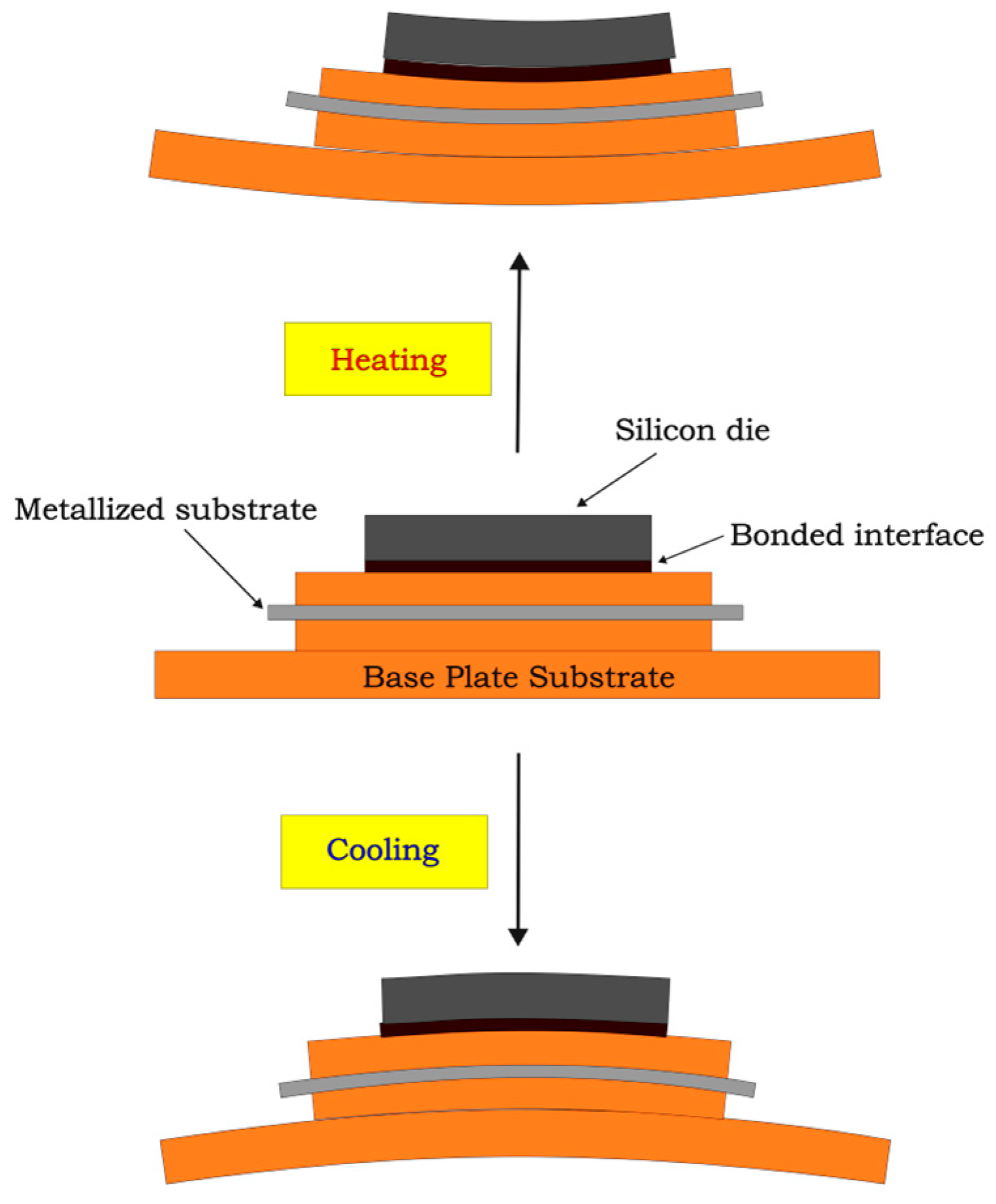
- In packaging, it is vital to closely match the coefficients of thermal expansion of substrate materials to those of semiconductors, like gallium nitride and silicon carbide to avoid issues caused by CTE mismatch (Figure 14).
4.2. Fuel Cells
- Their CTE values should be similar to those of other SOFC components;
- High levels of thermal and electrical conductivity;
- High levels of mechanical strength at high temperatures;
- Chemical stability in both oxidizing and reducing environments;
- Excellent imperviousness to oxygen and hydrogen.
4.3. Dental Implants
- Crown;
- Abutment;
- Implant body (or implant)
- Titanium implants have a much higher Young’s modulus (~120 GPa) than a typical human bone (~1 to 20 GPa). This results in the stress shielding of bone because most of the applied stress is loaded onto the implant. It can lead to lower than normal levels of stress on the surrounding bone, leading to less bone regeneration in that region and hence weaker surrounding bones over time, i.e., bone loss. This can cause the loosening of implants [283,284].
- The thermal conductivity of titanium implants is much higher than that of the human teeth they replace [285,286]. During the consumption of hot food and beverages, human teeth or dental implants undergo cyclic thermal loads. However, enamel and dentin layers in actual human teeth have low thermal conductivity, thereby protecting the sensitive inner pulp and bone inside gums from these temperature changes. However, this is not the case when dental implants are in use. These high food temperatures when transferred to alveolar bones in gums can cause permanent bone-death, also called necrosis, and the loss of bone regeneration and osseointegration. Necrosis can result from a thermal shock of 47 °C over just a minute [287,288], which can be easily caused by the excellent thermal conductivity of metal dental implants combined with intra-oral temperatures easily reaching 67–77 °C during day-to-day hot beverage consumption [289].
- Despite their biocompatibility advantages, titanium and its alloys tend to be more expensive than other implant alloy options like stainless steel [290].
- The problem of the high thermal conductivity of titanium implants can be alleviated by designing them with lattices, as used in mechanical metamaterials. Due to the porosity of lattices, the average thermal conductivity would be lower than that of a fully dense solid metal cross-section of the same size.
- The inner core of implant roots can be made of steel with a titanium covering on the outside if a negative- or low-expansion metamaterial lattice structure for a steel core is used. The low CTE of the lattice metamaterial structure would mitigate the problem of the high expansion of steels as compared to the CTE of human bone. Also, the overall cost of implants would decrease due to the lower use of titanium.
4.4. Space Structures
5. Conclusions
- The difference between constituents directly affects the NTE performance of the design along with the CTE of lower-thermal-expansion materials. A higher difference and a lower CTE of a low-expansion material tend to decrease the overall NTE. This is a general trend with the actual performance increase varying between different architectures.
- NTE designs have been manufactured using both AM and CM processes. In contrast to traditional manufacturing techniques, AM processes can create multimetal structures in a single machine with intricate details.
- The production of these structures has been explored using both polymers and metals. Fabrication using polymers offers the advantage of creating a greater difference in CTE between constituents, as some polymers have inherently higher CTE values than metals. On the other hand, metals provided greater stiffness values to the designs because of their higher strengths.
- The properties of multimaterial structures vary depending on the processes used in their production. AM techniques, characterized by rapid cooling rates, typically yield microstructures with fine grains and high strengths. In contrast, subtractive manufacturing CM methods exhibit lower cooling rates, resulting in coarser microstructures and other distinct differences.
- Achieving strong interfacial bonds is essential when constructing practical NTE systems. In processes that involve the application of heat to join diverse materials, the bond strength relies on the miscibility of the constituents and the formation of intermediate compounds. The use of equilibrium phase diagrams plays a crucial role in understanding the resultant bond strengths in combinations of multiple materials.
- Finally, we explored the diverse applications of NTE architectures across a range of fields, including biomedicine and energy production, highlighting their versatility and the specific needs they address.
Author Contributions
Funding
Conflicts of Interest
References
- Takenaka, K. Progress of research in negative thermal expansion materials: Paradigm shift in the control of thermal expansion. Front. Chem. 2018, 6, 267. [Google Scholar] [CrossRef] [PubMed]
- Takenaka, K. Negative thermal expansion materials: Technological key for control of thermal expansion. Sci. Technol. Adv. Mater. 2012, 13, 13001. [Google Scholar] [CrossRef] [PubMed]
- Devoto, D.; Paret, P.; Narumanchi, S.; Mihalic, M. Reliability of Bonded Interfaces for Automotive Power Electronics. 2013. In Proceedings of the ASME 2013 International Technical Conference and Exhibition on Packaging and Integration of Electronic and Photonic Microsystems. Volume 1: Advanced Packaging; Emerging Technologies; Modeling and Simulation; Multi-Physics Based Reliability; MEMS and NEMS; Materials and Processes, Burlingame, CA, USA, 16–18 July 2013. [Google Scholar] [CrossRef]
- Chen, J.; Hu, L.; Deng, J.; Xing, X. Negative thermal expansion in functional materials: Controllable thermal expansion by chemical modifications. Chem. Soc. Rev. 2015, 44, 3522–3567. [Google Scholar] [CrossRef] [PubMed]
- Evans, J.S.O. Negative thermal expansion materials †. J. Chem.Soc. DaltonTrans. 1999, 19, 3317–3326. [Google Scholar] [CrossRef]
- Chu, C.N.; Saka, N.; Suh, N.P. Negative thermal expansion ceramics: A review. Mater. Sci. Eng. 1987, 95, 303–308. [Google Scholar] [CrossRef]
- Mary, T.A.; Evans, J.S.O.; Vogt, T.; Sleight, A.W. Negative Thermal Expansion from 0.3 to 1050 Kelvin in ZrW2O8. Science 1996, 272, 90–92. [Google Scholar] [CrossRef]
- Takenaka, K.; Takagi, H. Giant negative thermal expansion in Ge-doped anti-perovskite manganese nitrides. Appl. Phys. Lett. 2005, 87, 261902. [Google Scholar] [CrossRef]
- Greve, B.K.; Martin, K.L.; Lee, P.L.; Chupas, P.J.; Chapman, K.W.; Wilkinson, A.P. Pronounced negative thermal expansion from a simple structure: Cubic ScF3. J. Am. Chem. Soc. 2010, 132, 15496–15498. [Google Scholar] [CrossRef]
- Evans, J.S.O.; Mary, T.A.; Sleight, A.W. Negative Thermal Expansion in a Large Molybdate and Tungstate Family. J. Solid State Chem. 1997, 133, 580–583. [Google Scholar] [CrossRef]
- Chapman, K.W.; Chupas, P.J.; Kepert, C.J. Compositional Dependence of Negative Thermal Expansion in the Prussian Blue Analogues MIIPtIV(CN)6 (M = Mn, Fe, Co, Ni, Cu, Zn, Cd). J. Am. Chem. Soc. 2006, 128, 7009–7014. [Google Scholar] [CrossRef]
- Lakes, R. Cellular solid structures with unbounded thermal expansion. J. Mater. Sci. Lett. 1996, 15, 475–477. [Google Scholar] [CrossRef]
- Lakes, R. Cellular solids with tunable positive or negative thermal expansion of unbounded magnitude. Appl. Phys. Lett. 2007, 90, 221905. [Google Scholar] [CrossRef]
- Lehman, J.; Lakes, R. Stiff lattices with zero thermal expansion. J. Intell. Mater. Syst. Struct. 2012, 23, 1263–1268. [Google Scholar] [CrossRef]
- Lehman, J.; Lakes, R. Stiff, strong zero thermal expansion lattices via the Poisson effect. J. Mater. Res. 2013, 28, 2499–2508. [Google Scholar] [CrossRef][Green Version]
- Ha, C.S.; Hestekin, E.; Li, J.; Plesha, M.E.; Lakes, R.S. Controllable thermal expansion of large magnitude in chiral negative Poisson’s ratio lattices. Phys. Status Solidi B Basic Res. 2015, 252, 1431–1434. [Google Scholar] [CrossRef]
- Grima, J.N.; Farrugia, P.S.; Gatt, R.; Zammit, V. A system with adjustable positive or negative thermal expansion. Proc. R. Soc. A Math. Phys. Eng. Sci. 2007, 463, 1585–1596. [Google Scholar] [CrossRef]
- Grima, J.N.; Bajada, M.; Scerri, S.; Attard, D.; Dudek, K.K.; Gatt, R. Maximizing negative thermal expansion via rigid unit modes: A geometry-based approach. Proc. R. Soc. A Math. Phys. Eng. Sci. 2015, 471, 20150188. [Google Scholar] [CrossRef] [PubMed]
- Grima, J.N.; Oliveri, L.; Ellul, B.; Gatt, R.; Attard, D.; Cicala, G.; Recca, G. Adjustable and negative thermal expansion from multilayered systems. Phys. Status Solidi Rapid Res. Lett. 2010, 4, 133–135. [Google Scholar] [CrossRef]
- Wu, L.; Li, B.; Zhou, J. Isotropic Negative Thermal Expansion Metamaterials. ACS Appl. Mater. Interfaces 2016, 8, 17721–17727. [Google Scholar] [CrossRef] [PubMed]
- Steeves, C.A.; Lucato, S.L.D.S.E.; He, M.; Antinucci, E.; Hutchinson, J.W.; Evans, A.G. Concepts for structurally robust materials that combine low thermal expansion with high stiffness. J. Mech. Phys. Solids 2007, 55, 1803–1822. [Google Scholar] [CrossRef]
- Wei, K.; Chen, H.; Pei, Y.; Fang, D. Planar lattices with tailorable coefficient of thermal expansion and high stiffness based on dual-material triangle unit. J. Mech. Phys. Solids 2016, 86, 173–191. [Google Scholar] [CrossRef]
- Li, Y.; Chen, Y.; Li, T.; Cao, S.; Wang, L. Hoberman-sphere-inspired lattice metamaterials with tunable negative thermal expansion. Compos. Struct. 2018, 189, 586–597. [Google Scholar] [CrossRef]
- Jefferson, G.; Parthasarathy, T.A.; Kerans, R.J. Tailorable thermal expansion hybrid structures. Int. J. Solids Struct. 2009, 46, 2372–2387. [Google Scholar] [CrossRef]
- Ai, L.; Gao, X.L. Three-dimensional metamaterials with a negative Poisson’s ratio and a non-positive coefficient of thermal expansion. Int. J. Mech. Sci. 2018, 135, 101–113. [Google Scholar] [CrossRef]
- Ai, L.; Gao, X.L. Metamaterials with negative Poisson’s ratio and non-positive thermal expansion. Compos. Struct. 2017, 162, 70–84. [Google Scholar] [CrossRef]
- Raminhos, J.S.; Borges, J.P.; Velhinho, A. Development of polymeric anepectic meshes: Auxetic metamaterials with negative thermal expansion. Smart Mater. Struct. 2019, 28, 45010. [Google Scholar] [CrossRef]
- Lim, T.C. Auxetic and Negative Thermal Expansion Structure Based on Interconnected Array of Rings and Sliding Rods. Phys. Status Solidi B Basic Res. 2017, 254, 1600775. [Google Scholar] [CrossRef]
- Lim, T.C. Negative thermal expansion structures constructed from positive thermal expansion trusses. J. Mater. Sci. 2012, 47, 368–373. [Google Scholar] [CrossRef]
- Xu, H.; Pasini, D. Structurally efficient three-dimensional metamaterials with controllable thermal expansion. Sci. Rep. 2016, 6, 34924. [Google Scholar] [CrossRef]
- Xu, H.; Farag, A.; Pasini, D. Routes to program thermal expansion in three-dimensional lattice metamaterials built from tetrahedral building blocks. J. Mech. Phys. Solids 2018, 117, 54–87. [Google Scholar] [CrossRef]
- Jin, Z.H. A microlattice material with negative or zero thermal expansion. Compos. Commun. 2017, 6, 48–51. [Google Scholar] [CrossRef]
- Juasiripukdee, P.; Maskery, I.; Ashcroft, I.; Leach, R. Low thermal expansion machine frame designs using lattice structures. Appl. Sci. 2021, 11, 9135. [Google Scholar] [CrossRef]
- Peng, X.L.; Bargmann, S. Tunable auxeticity and isotropic negative thermal expansion in three-dimensional lattice structures of cubic symmetry. Extreme Mech. Lett. 2021, 43, 101201. [Google Scholar] [CrossRef]
- Peng, X.L.; Bargmann, S. A novel hybrid-honeycomb structure: Enhanced stiffness, tunable auxeticity and negative thermal expansion. Int. J. Mech. Sci. 2021, 190, 106021. [Google Scholar] [CrossRef]
- Ha, C.S.; Plesha, M.E.; Lakes, R.S. Simulations of thermoelastic triangular cell lattices with bonded joints by finite element analysis. Extrem. Mech. Lett. 2017, 12, 101–107. [Google Scholar] [CrossRef]
- Lim, T.-C. Anisotropic and negative thermal expansion behavior in a cellular microstructure. J. Mater. Sci. 2005, 40, 3275–3277. [Google Scholar] [CrossRef]
- Deshpande, V.S.; Ashby, M.F.; Fleck, N.A. Foam topology: Bending versus stretching dominated architectures. Acta Mater. 2001, 49, 1035–1040. [Google Scholar] [CrossRef]
- Thompson, S.M.; Bian, L.; Shamsaei, N.; Yadollahi, A. An overview of Direct Laser Deposition for additive manufacturing; Part I: Transport phenomena, modeling and diagnostics. Addit. Manuf. 2015, 8, 36–62. [Google Scholar] [CrossRef]
- Pereira, T.; Kennedy, J.V.; Potgieter, J. A comparison of traditional manufacturing vs additive manufacturing, the best method for the job. In Procedia Manufacturing; Elsevier B.V.: Amsterdam, The Netherlands, 2019; pp. 11–18. [Google Scholar] [CrossRef]
- Ding, X.; Wang, L. Heat transfer and fluid flow of molten pool during selective laser melting of AlSi10Mg powder: Simulation and experiment. J. Manuf. Process. 2017, 26, 280–289. [Google Scholar] [CrossRef]
- Zhang, B.; Li, Y.; Bai, Q. Defect Formation Mechanisms in Selective Laser Melting: A Review. Chin. J. Mech. Eng. Engl. Ed. 2017, 30, 515–527. [Google Scholar] [CrossRef]
- Cao, L. Mesoscopic-scale numerical investigation including the influence of scanning strategy on selective laser melting process. Comput. Mater. Sci. 2021, 189, 110263. [Google Scholar] [CrossRef]
- Chen, K.; Wang, C.; Hong, Q.; Wen, S.; Zhou, Y.; Yan, C.; Shi, Y. Selective laser melting 316L/CuSn10 multi-materials: Processing optimization, interfacial characterization and mechanical property. J. Mater. Process. Technol. 2020, 283, 116701. [Google Scholar] [CrossRef]
- Mei, X.; Wang, X.; Peng, Y.; Gu, H.; Zhong, G.; Yang, S. Interfacial characterization and mechanical properties of 316L stainless steel/inconel 718 manufactured by selective laser melting. Mater. Sci. Eng. A 2019, 758, 185–191. [Google Scholar] [CrossRef]
- Chen, J.; Yang, Y.; Song, C.; Zhang, M.; Wu, S.; Wang, D. Interfacial microstructure and mechanical properties of 316L /CuSn10 multi-material bimetallic structure fabricated by selective laser melting. Mater. Sci. Eng. A 2019, 752, 75–85. [Google Scholar] [CrossRef]
- Sing, S.L.; Lam, L.P.; Zhang, D.Q.; Liu, Z.H.; Chua, C.K. Interfacial characterization of SLM parts in multi-material processing: Intermetallic phase formation between AlSi10Mg and C18400 copper alloy. Mater. Charact. 2015, 107, 220–227. [Google Scholar] [CrossRef]
- Liu, Z.H.; Zhang, D.Q.; Sing, S.L.; Chua, C.K.; Loh, L.E. Interfacial characterization of SLM parts in multi-material processing: Metallurgical diffusion between 316L stainless steel and C18400 copper alloy. Mater. Charact. 2014, 94, 116–125. [Google Scholar] [CrossRef]
- Tan, C.; Zhou, K.; Ma, W.; Min, L. Interfacial characteristic and mechanical performance of maraging steel-copper functional bimetal produced by selective laser melting based hybrid manufacture. Mater. Des. 2018, 155, 77–85. [Google Scholar] [CrossRef]
- Thijs, L.; Verhaeghe, F.; Craeghs, T.; Van Humbeeck, J.; Kruth, J.-P. A study of the microstructural evolution during selective laser melting of Ti-6Al-4V. Acta Mater. 2010, 58, 3303–3312. [Google Scholar] [CrossRef]
- Anwar, A.B.; Pham, Q.-C. Study of the spatter distribution on the powder bed during selective laser melting. Addit. Manuf. 2018, 22, 86–97. [Google Scholar] [CrossRef]
- Kasperovich, G.; Haubrich, J.; Gussone, J.; Requena, G. Correlation between porosity and processing parameters in TiAl6V4 produced by selective laser melting. Mater. Des. 2016, 105, 160–170. [Google Scholar] [CrossRef]
- King, W.E.; Barth, H.; Castillo, V.; Gallegos, G.; Gibbs, J.; Hahn, D.; Kamath, C.; Rubenchik, A. Observation of keyhole-mode laser melting in laser powder-bed fusion additive manufacturing. J. Mater. Process. Technol. 2014, 214, 2915–2925. [Google Scholar] [CrossRef]
- Zhang, M.; Yang, Y.; Wang, D.; Song, C.; Chen, J. Microstructure and mechanical properties of CuSn/18Ni300 bimetallic porous structures manufactured by selective laser melting. Mater. Des. 2019, 165, 107583. [Google Scholar] [CrossRef]
- Shakerin, S.; Hadadzadeh, A.; Amirkhiz, B.S.; Shamsdini, S.; Li, J.; Mohammadi, M. Additive manufacturing of maraging steel-H13 bimetals using laser powder bed fusion technique. Addit. Manuf. 2019, 29, 100797. [Google Scholar] [CrossRef]
- Tan, C.; Zhang, X.; Dong, D.; Attard, B.; Wang, D.; Kuang, M.; Ma, W.; Zhou, K. In-situ synthesised interlayer enhances bonding strength in additively manufactured multi-material hybrid tooling. Int. J. Mach. Tools Manuf. 2020, 155, 103592. [Google Scholar] [CrossRef]
- Wang, P.; Lao, C.; Chen, Z.; Liu, Y.; Wang, H.; Wendrock, H.; Eckert, J.; Scudino, S. Microstructure and mechanical properties of Al-12Si and Al-3.5Cu-1.5Mg-1Si bimetal fabricated by selective laser melting. J. Mater. Sci. Technol. 2020, 36, 18–26. [Google Scholar] [CrossRef]
- Wei, K.; Zeng, X.; Li, F.; Liu, M.; Deng, J. Microstructure and Mechanical Property of Ti-5Al-2.5Sn/Ti-6Al-4V Dissimilar Titanium Alloys Integrally Fabricated by Selective Laser Melting. JOM 2020, 72, 1031–1038. [Google Scholar] [CrossRef]
- Tey, C.F.; Tan, X.; Sing, S.L.; Yeong, W.Y. Additive manufacturing of multiple materials by selective laser melting: Ti-alloy to stainless steel via a Cu-alloy interlayer. Addit. Manuf. 2020, 31, 100970. [Google Scholar] [CrossRef]
- Scaramuccia, M.G.; Demir, A.G.; Caprio, L.; Tassa, O.; Previtali, B. Development of processing strategies for multigraded selective laser melting of Ti6Al4V and IN718. Powder Technol. 2020, 367, 376–389. [Google Scholar] [CrossRef]
- Wei, C.; Li, L.; Zhang, X.; Chueh, Y.H. 3D printing of multiple metallic materials via modified selective laser melting. CIRP Ann. 2018, 67, 245–248. [Google Scholar] [CrossRef]
- Wei, C.; Liu, L.; Gu, Y.; Huang, Y.; Chen, Q.; Li, Z.; Li, L. Multi-material additive-manufacturing of tungsten–copper alloy bimetallic structure with a stainless-steel interlayer and associated bonding mechanisms. Addit. Manuf. 2022, 50, 102574. [Google Scholar] [CrossRef]
- Frazier, W.E. Metal additive manufacturing: A review. J. Mater. Eng. Perform. 2014, 23, 1917–1928. [Google Scholar] [CrossRef]
- Ahn, D.G. Direct metal additive manufacturing processes and their sustainable applications for green technology: A review. Int. J. Precis. Eng. Manuf. Green Technol. 2016, 3, 381–395. [Google Scholar] [CrossRef]
- Dass, A.; Moridi, A. State of the art in directed energy deposition: From additive manufacturing to materials design. Coatings 2019, 9, 418. [Google Scholar] [CrossRef]
- Ding, D.; Pan, Z.; Cuiuri, D.; Li, H. Wire-feed additive manufacturing of metal components: Technologies, developments and future interests. Int. J. Adv. Manuf. Technol. 2015, 81, 465–481. [Google Scholar] [CrossRef]
- Sibisi, T.H.; Shongwe, M.B.; Tshabalala, L.C.; Mathoho, I. LAM additive manufacturing: A fundamental review on mechanical properties, common defects, dominant processing variables, and its applications. Int. J. Adv. Manuf. Technol. 2023, 128, 2847–2861. [Google Scholar] [CrossRef]
- Williams, S.W.; Martina, F.; Addison, A.C.; Ding, J.; Pardal, G.; Colegrove, P. Wire + Arc additive manufacturing. Mater. Sci. Technol. 2016, 32, 641–647. [Google Scholar] [CrossRef]
- Casalino, G.; Karamimoghadam, M.; Contuzzi, N. Metal Wire Additive Manufacturing: A Comparison between Arc Laser and Laser/Arc Heat Sources. Inventions 2023, 8, 52. [Google Scholar] [CrossRef]
- Osipovich, K.; Kalashnikov, K.; Chumaevskii, A.; Gurianov, D.; Kalashnikova, T.; Vorontsov, A.; Zykova, A.; Utyaganova, V.; Panfilov, A.; Nikolaeva, A.; et al. Wire-Feed Electron Beam Additive Manufacturing: A Review. Metals 2023, 13, 279. [Google Scholar] [CrossRef]
- Feenstra, D.R.; Banerjee, R.; Fraser, H.L.; Huang, A.; Molotnikov, A.; Birbilis, N. Critical review of the state of the art in multi-material fabrication via directed energy deposition. Curr. Opin. Solid State Mater. Sci. 2021, 25, 100924. [Google Scholar] [CrossRef]
- Zhang, Y.; Bandyopadhyay, A. Direct fabrication of bimetallic Ti6Al4V+Al12Si structures via additive manufacturing. Addit. Manuf. 2019, 29, 100783. [Google Scholar] [CrossRef]
- Thiriet, A.; Schneider-Maunoury, C.; Laheurte, P.; Boisselier, D.; Weiss, L. Multiscale study of different types of interface of a buffer material in powder-based directed energy deposition: Example of Ti6Al4V/Ti6Al4V—Mo/Mo—Inconel 718. Addit. Manuf. 2019, 27, 118–130. [Google Scholar] [CrossRef]
- Zhang, J.; Zhang, Y.; Li, W.; Karnati, S.; Liou, F.; Newkirk, J.W. Microstructure and properties of functionally graded materials Ti6Al4V/TiC fabricated by direct laser deposition. Rapid Prototyp. J. 2018, 24, 677–687. [Google Scholar] [CrossRef]
- Li, X.C.; Stampfl, J.; Prinz, F.B. Mechanical and Thermal Expansion Behavior of Laser Deposited Metal Matrix Composites of Invar and TiC. Mater. Sci. Eng. A 2000, 282, 86–90. [Google Scholar] [CrossRef]
- Bobbio, L.D.; Bocklund, B.; Otis, R.; Borgonia, J.; Dillon, R.; Shapiro, A.; McEnerney, B.; Liu, Z.; Beese, A. Experimental analysis and thermodynamic calculations of an additively manufactured functionally graded material of v to Invar 36. J. Mater. Res. 2018, 33, 1642–1649. [Google Scholar] [CrossRef]
- Zuback, J.S.; Palmer, T.A.; DebRoy, T. Additive manufacturing of functionally graded transition joints between ferritic and austenitic alloys. J. Alloys Compd. 2019, 770, 995–1003. [Google Scholar] [CrossRef]
- Li, W.; Chen, X.; Yan, L.; Zhang, J.; Zhang, X.; Liou, F. Additive manufacturing of a new Fe-Cr-Ni alloy with gradually changing compositions with elemental powder mixes and thermodynamic calculation. Int. J. Adv. Manuf. Technol. 2018, 95, 1013–1023. [Google Scholar] [CrossRef]
- Kunimine, T.; Miyazaki, R.; Yamashita, Y.; Funada, Y. Effects of Laser-Beam Defocus on Microstructural Features of Compositionally Graded WC/Co-Alloy Composites Additively Manufactured by Multi-Beam Laser Directed Energy Deposition. Sci. Rep. 2020, 10, 8975. [Google Scholar] [CrossRef] [PubMed]
- Wang, X.; Zhang, Z.; Men, Y.; Li, X.; Liang, Y.; Ren, L. Fabrication of nano-TiC functional gradient wear-resistant composite coating on 40Cr gear steel using laser cladding under starved lubrication conditions. Opt. Laser Technol. 2020, 126, 106136. [Google Scholar] [CrossRef]
- Lin, X.; Yue, T.M.; Yang, H.O.; Huang, W.D. Laser rapid forming of SS316L/Rene88DT graded material. Mater. Sci. Eng. A 2005, 391, 325–336. [Google Scholar] [CrossRef]
- Ben-Artzy, A.; Reichardt, A.; Borgonia, J.; Dillon, R.; McEnerney, B.; Shapiro, A.; Hosemann, P. Compositionally graded SS316 to C300 Maraging steel using additive manufacturing. Mater. Des. 2021, 201, 109500. [Google Scholar] [CrossRef]
- Ramakrishnan, A.; Dinda, G.P. Microstructural control of an Al–W aluminum matrix composite during direct laser metal deposition. J. Alloys Compd. 2020, 813, 152208. [Google Scholar] [CrossRef]
- Li, J.C.; Lin, X.; Kang, N.; Lu, J.L.; Wang, Q.Z.; Huang, W.D. Microstructure, tensile and wear properties of a novel graded Al matrix composite prepared by direct energy deposition. J. Alloys Compd. 2020, 826, 154077. [Google Scholar] [CrossRef]
- Pei, Y.T.; De Hosson, J.T.M. Functionally graded materials produced by laser cladding. Acta Mater. 2000, 48, 2617–2624. [Google Scholar] [CrossRef]
- Chen, N.; Khan, H.; Wan, Z.; Lippert, J.; Sun, H.; Shang, S.; Liu, Z.; Li, J. Microstructural characteristics and crack formation in additively manufactured bimetal material of 316L stainless steel and Inconel 625. Addit. Manuf. 2020, 32, 101037. [Google Scholar] [CrossRef]
- Zhang, X.; Sun, C.; Pan, T.; Flood, A.; Zhang, Y.; Li, L.; Liou, F. Additive manufacturing of copper—H13 tool steel bi-metallic structures via Ni-based multi-interlayer. Addit. Manuf. 2020, 36, 101474. [Google Scholar] [CrossRef]
- Liu, W.; DuPont, J.N. Fabrication of functionally graded TiC/Ti composites by laser engineered net shaping. Scr. Mater. 2003, 48, 1337–1342. [Google Scholar] [CrossRef]
- Feenstra, D.R.; Molotnikov, A.; Birbilis, N. Effect of energy density on the interface evolution of stainless steel 316L deposited upon INC 625 via directed energy deposition. J. Mater. Sci. 2020, 55, 13314–13328. [Google Scholar] [CrossRef]
- Li, W.; Karnati, S.; Kriewall, C.; Liou, F.; Newkirk, J.; Brown Taminger, K.; Seufzer, W. Fabrication and characterization of a functionally graded material from Ti-6Al-4V to SS316 by laser metal deposition. Addit. Manuf. 2017, 14, 95–104. [Google Scholar] [CrossRef]
- Onuike, B.; Bandyopadhyay, A. Functional bimetallic joints of Ti6Al4V to SS410. Addit. Manuf. 2020, 31, 100931. [Google Scholar] [CrossRef]
- Babuska, T.F.; Krick, B.A.; Susan, D.F.; Kustas, A.B. Comparison of powder bed fusion and directed energy deposition for tailoring mechanical properties of traditionally brittle alloys. Manuf. Lett. 2021, 28, 30–34. [Google Scholar] [CrossRef]
- Svetlizky, D.; Das, M.; Zheng, B.; Vyatskikh, A.; Bose, S.; Bandyopadhyay, A.; Schoenung, J.; Lavernia, E.; Eliaz, N. Directed energy deposition (DED) additive manufacturing: Physical characteristics, defects, challenges and applications. Mater. Today 2021, 49, 271–295. [Google Scholar] [CrossRef]
- Pham, N.T.-H.; Nguyen, V.-T. Wear Properties of TiC-Reinforced Co50 Composite Coatings from Room Temperature to High Temperature. Adv. Mater. Sci. Eng. 2020, 2020, 6849081. [Google Scholar] [CrossRef]
- Farren, J.D.; DuPont, J.N.; Noecker, F.F. Fabrication of a carbon steel-to-stainless steel transition joint using direct laser deposition-A feasibility study. Weld. J. 2007, 86, 55. [Google Scholar]
- Kim, D.K.; Woo, W.; Kim, E.Y.; Choi, S.H. Microstructure and mechanical characteristics of multi-layered materials composed of 316L stainless steel and ferritic steel produced by direct energy deposition. J. Alloys Compd. 2019, 774, 896–907. [Google Scholar] [CrossRef]
- Soodi, M.; Masood, S.H.; Brandt, M. Thermal expansion of functionally graded and wafer-layered structures produced by laser direct metal deposition. Int. J. Adv. Manuf. Technol. 2013, 69, 2011–2018. [Google Scholar] [CrossRef]
- Eliseeva, O.V.; Kirk, T.; Samimi, P.; Malak, R.; Arróyave, R.; Elwany, A.; Karaman, I. Functionally Graded Materials through robotics-inspired path planning. Mater. Des. 2019, 182, 107975. [Google Scholar] [CrossRef]
- Su, Y.; Chen, B.; Tan, C.; Song, X.; Feng, J. Influence of composition gradient variation on the microstructure and mechanical properties of 316 L/Inconel718 functionally graded material fabricated by laser additive manufacturing. J. Mater. Process. Technol. 2020, 283, 116702. [Google Scholar] [CrossRef]
- Yadav, S.; Jinoop, A.N.; Sinha, N.; Paul, C.P.; Bindra, K.S. Parametric investigation and characterization of laser directed energy deposited copper-nickel graded layers. Int. J. Adv. Manuf. Technol. 2020, 108, 3779–3791. [Google Scholar] [CrossRef]
- Griffith, M.L.; Harwell, L.D.; Romero, J.T.; Schlienger, E.; Atwood, C.L.; Smugeresky, J.E. Multi-Material Processing by Lens. In Proceedings of the International Solid Freeform Fabrication Symposium, Austin, TX, USA, 11–13 August 1997. [Google Scholar] [CrossRef]
- Meng, W.; Zhang, W.; Zhang, W.; Yin, X.; Cui, B. Fabrication of steel-Inconel functionally graded materials by laser melting deposition integrating with laser synchronous preheating. Opt. Laser Technol. 2020, 131, 106451. [Google Scholar] [CrossRef]
- Carroll, B.E.; Otis, R.; Borgonia, J.; Suh, J.; Dillon, R.; Shapiro, A.; Hofmann, D.; Liu, Z.; Beese, A. Functionally graded material of 304L stainless steel and inconel 625 fabricated by directed energy deposition: Characterization and thermodynamic modeling. Acta Mater. 2016, 108, 46–54. [Google Scholar] [CrossRef]
- Ni, X.; Zhang, L.; Wu, W.; Zhu, D.; Kong, D.; Dong, C.; Zhu, G. Functionally Nb graded inconel 718 alloys fabricated by laser melting deposition: Mechanical properties and corrosion behavior. Anti-Corros. Methods Mater. 2020, 67, 16–23. [Google Scholar] [CrossRef]
- Onuike, B.; Heer, B.; Bandyopadhyay, A. Additive manufacturing of Inconel 718—Copper alloy bimetallic structure using laser engineered net shaping (LENSTM). Addit. Manuf. 2018, 21, 133–140. [Google Scholar] [CrossRef]
- Chen, B.; Wang, T.; Xi, X.; Tan, C.; Song, X. Additive manufacturing of Ti-Al functionally graded material by laser based directed energy deposition. Rapid. Prototyp. J. 2023, 29, 558–568. [Google Scholar] [CrossRef]
- Schneider-Maunoury, C.; Weiss, L.; Acquier, P.; Boisselier, D.; Laheurte, P. Functionally graded Ti6Al4V-Mo alloy manufactured with DED-CLAD® process. Addit. Manuf. 2017, 17, 55–66. [Google Scholar] [CrossRef]
- Meng, W.; Xiaohui, Y.; Zhang, W.; Junfei, F.; Lijie, G.; Qunshuang, M.; Bing, C. Additive manufacturing of a functionally graded material from Inconel625 to Ti6Al4V by laser synchronous preheating. J. Mater. Process. Technol. 2020, 275, 116368. [Google Scholar] [CrossRef]
- Sun, Z.; Ji, X.; Zhang, W.; Chang, L.; Xie, G.; Chang, H.; Zhou, L. Microstructure evolution and high temperature resistance of Ti6Al4V/Inconel625 gradient coating fabricated by laser melting deposition. Mater. Des. 2020, 191, 108644. [Google Scholar] [CrossRef]
- Sahasrabudhe, H.; Harrison, R.; Carpenter, C.; Bandyopadhyay, A. Stainless steel to titanium bimetallic structure using LENSTM. Addit. Manuf. 2015, 5, 1–8. [Google Scholar] [CrossRef]
- Bobbio, L.D.; Otis, R.; Borgonia, J.; Dillon, R.; Shapiro, A.; Liu, Z.; Beese, A. Additive manufacturing of a functionally graded material from Ti-6Al-4V to Invar: Experimental characterization and thermodynamic calculations. Acta Mater. 2017, 127, 133–142. [Google Scholar] [CrossRef]
- Krishna, B.V.; Xue, W.; Bose, S.; Bandyopadhyay, A. Functionally graded Co–Cr–Mo coating on Ti–6Al–4V alloy structures. Acta Biomater. 2008, 4, 697–706. [Google Scholar] [CrossRef]
- Li, W.; Zhang, J.; Zhang, X.; Liou, F. Effect of optimizing particle size on directed energy deposition of Functionally Graded Material with blown Pre-Mixed Multi-Powder. Manuf. Lett. 2017, 13, 39–43. [Google Scholar] [CrossRef]
- Shang, C.; Wang, C.; Li, C.; Yang, G.; Xu, G.; You, J. Eliminating the crack of laser 3D printed functionally graded material from TA15 to Inconel718 by base preheating. Opt. Laser Technol. 2020, 126, 106100. [Google Scholar] [CrossRef]
- Wang, F.; Mei, J.; Wu, X. Direct laser fabrication of Ti6Al4V/TiB. J. Mater. Process. Technol. 2008, 195, 321–326. [Google Scholar] [CrossRef]
- Wang, F.; Mei, J.; Wu, X. Microstructure study of direct laser fabricated Ti alloys using powder and wire. Appl. Surf. Sci. 2006, 253, 1424–1430. [Google Scholar] [CrossRef]
- Ma, R.; Liu, Z.; Wang, W.; Xu, G.; Wang, W. Laser deposition melting of TC4/TiAl functionally graded material. Vacuum 2020, 177, 109349. [Google Scholar] [CrossRef]
- Qu, H.P.; Li, P.; Zhang, S.Q.; Li, A.; Wang, H.M. Microstructure and mechanical property of laser melting deposition (LMD) Ti/TiAl structural gradient material. Mater. Des. 2010, 31, 574–582. [Google Scholar] [CrossRef]
- Liu, Y.; Liu, C.; Liu, W.; Ma, Y.; Zhang, C.; Cai, Q.; Liu, B. Microstructure and properties of Ti/Al lightweight graded material by direct laser deposition. Mater. Sci. Technol. 2018, 34, 945–951. [Google Scholar] [CrossRef]
- Schneider-Maunoury, C.; Weiss, L.; Perroud, O.; Joguet, D.; Boisselier, D.; Laheurte, P. An application of differential injection to fabricate functionally graded Ti-Nb alloys using DED-CLAD® process. J. Mater. Process. Technol. 2019, 268, 171–180. [Google Scholar] [CrossRef]
- Zhang, Y.Z.; Meacock, C.; Vilar, R. Laser powder micro-deposition of compositional gradient Ti–Cr alloy. Mater. Des. 2010, 31, 3891–3895. [Google Scholar] [CrossRef]
- Liu, Y.; Liang, C.; Liu, W.; Ma, Y.; Liu, C.; Zhang, C. Dilution of Al and V through laser powder deposition enables a continuously compositionally Ti/Ti6Al4V graded structure. J. Alloys Compd. 2018, 763, 376–383. [Google Scholar] [CrossRef]
- Hu, Y.; Ning, F.; Wang, H.; Cong, W.; Zhao, B. Laser engineered net shaping of quasi-continuous network microstructural TiB reinforced titanium matrix bulk composites: Microstructure and wear performance. Opt. Laser Technol. 2018, 99, 174–183. [Google Scholar] [CrossRef]
- Hu, Y.; Zhao, B.; Ning, F.; Wang, H.; Cong, W. In-situ ultrafine three-dimensional quasi-continuous network microstructural TiB reinforced titanium matrix composites fabrication using laser engineered net shaping. Mater. Lett. 2017, 195, 116–119. [Google Scholar] [CrossRef]
- Lima, D.D.; Mantri, S.; Mikler, C.; Contieri, R.; Yannetta, C.; Campo, K.; Lopes, E.; Styles, M.; Borkar, T.; Caram, R.; et al. Laser additive processing of a functionally graded internal fracture fixation plate. Mater. Des. 2017, 130, 8–15. [Google Scholar] [CrossRef]
- Hofmann, D.C.; Roberts, S.; Otis, R.; Kolodziejska, J.; Dillon, R.; Suh, J.; Shapiro, A.A.; Liu, Z.; Borgonia, J. Developing Gradient Metal Alloys through Radial Deposition Additive Manufacturing. Sci. Rep. 2014, 4, 5357. [Google Scholar] [CrossRef] [PubMed]
- Choi, J.-W.; Kim, H.-C.; Wicker, R. Multi-material stereolithography. J. Mater. Process. Technol. 2011, 211, 318–328. [Google Scholar] [CrossRef]
- Wicker, R.; Medina, F.; Elkins, C. Muti-Material Stereolithography. US Patent US7556490B2; filed 30 July 2004 and issued 7 July 2009,
- Inamdar, A.; Magana, M.; Medina, F.; Grajeda, Y.; Wicker, R. Development of an automated multiple material stereolithography machine. In Proceedings of the 2006 International Solid Freeform Fabrication Symposium, Austin, TX, USA, 14–16 August 2006. [Google Scholar]
- Espalin, D.; Ramirez, J.A.; Medina, F.; Wicker, R. Multi-material, multi-technology FDM: Exploring build process variations. Rapid Prototyp. J. 2014, 20, 236–244. [Google Scholar] [CrossRef]
- Ali, M.H.; Mir-Nasiri, N.; Ko, W.L. Multi-nozzle extrusion system for 3D printer and its control mechanism. Int. J. Adv. Manuf. Technol. 2016, 86, 999–1010. [Google Scholar] [CrossRef]
- Rocha, V.G.; Saiz, E.; Tirichenko, I.S.; García-Tuñón, E. Direct ink writing advances in multi-material structures for a sustainable future. J. Mater. Chem. A Mater. 2020, 8, 15646–15657. [Google Scholar] [CrossRef]
- Compton, B.G.; Lewis, J.A. 3D-Printing of Lightweight Cellular Composites. Adv. Mater. 2014, 26, 5930–5935. [Google Scholar] [CrossRef]
- Rocha, V.G.; Garcia-Tunon, E.; Botas, C.; Markoulidis, F.; Feilden, E.; D’Elia, E.; Ni, N.; Shaffer, M.; Saiz, E. Multimaterial 3D Printing of Graphene-Based Electrodes for Electrochemical Energy Storage Using Thermoresponsive Inks. ACS Appl. Mater. Interfaces 2017, 9, 37136–37145. [Google Scholar] [CrossRef]
- Mueller, J.; Raney, J.R.; Shea, K.; Lewis, J.A. Architected Lattices with High Stiffness and Toughness via Multicore–Shell 3D Printing. Adv. Mater. 2018, 30, 1705001. [Google Scholar] [CrossRef]
- Nazir, A.; Gokcekaya, O.; Md Masum Billah, K.; Ertugrul, O.; Jiang, J.; Sun, J.; Hussain, S. Multi-material additive manufacturing: A systematic review of design, properties, applications, challenges, and 3D printing of materials and cellular metamaterials. Mater. Des. 2023, 226, 111661. [Google Scholar] [CrossRef]
- Gander, J.D.; Giacomin, A.J. Review of die lip buildup in plastics extrusion. Polym. Eng. Sci. 1997, 37, 1113–1126. [Google Scholar] [CrossRef]
- Unkovskiy, A.; Wahl, E.; Huettig, F.; Keutel, C.; Spintzyk, S. Multimaterial 3D printing of a definitive silicone auricular prosthesis: An improved technique. J. Prosthet. Dent. 2021, 125, 946–950. [Google Scholar] [CrossRef] [PubMed]
- Hu, Q.; Rance, G.; Trindade, G.; Pervan, D.; Jiang, L.; Foerster, A.; Turyanska, L.; Tuck, C.; Irvine, D.; Hague, R.; et al. The influence of printing parameters on multi-material two-photon polymerisation based micro additive manufacturing. Addit. Manuf. 2022, 51, 102575. [Google Scholar] [CrossRef]
- Lu, L.; Tang, X.; Hu, S.; Pan, Y. Acoustic Field-Assisted Particle Patterning for Smart Polymer Composite Fabrication in Stereolithography. 3D Print Addit. Manuf. 2018, 5, 151–159. [Google Scholar] [CrossRef]
- Jiang, C.-P.; Hentihu, M.F.R.; Lee, S.-Y.; Lin, R. Multiresin Additive Manufacturing Process for Printing a Complete Denture and an Analysis of Accuracy. 3D Print Addit. Manuf. 2022, 9, 511–519. [Google Scholar] [CrossRef] [PubMed]
- Mansouri, M.R.; Montazerian, H.; Schmauder, S.; Kadkhodapour, J. 3D-printed multimaterial composites tailored for compliancy and strain recovery. Compos. Struct. 2018, 184, 11–17. [Google Scholar] [CrossRef]
- Sarvestani, H.Y.; Akbarzadeh, A.H.; Therriault, D.; Lévesque, M. Engineered bi-material lattices with thermo-mechanical programmability. Compos. Struct. 2021, 263, 113705. [Google Scholar] [CrossRef]
- Lopes, L.R.; Silva, A.F.; Carneiro, O.S. Multi-material 3D printing: The relevance of materials affinity on the boundary interface performance. Addit. Manuf. 2018, 23, 45–52. [Google Scholar] [CrossRef]
- Yin, J.; Lu, C.; Fu, J.; Huang, Y.; Zheng, Y. Interfacial bonding during multi-material fused deposition modeling (FDM) process due to inter-molecular diffusion. Mater. Des. 2018, 150, 104–112. [Google Scholar] [CrossRef]
- Lin, W.; Shen, H.; Xu, G.; Zhang, L.; Fu, J.; Deng, X. Single-layer temperature-adjusting transition method to improve the bond strength of 3D-printed PCL/PLA parts. Compos Part A Appl. Sci. Manuf. 2018, 115, 22–30. [Google Scholar] [CrossRef]
- Mueller, J.; Lewis, J.A.; Bertoldi, K. Architected Multimaterial Lattices with Thermally Programmable Mechanical Response. Adv. Funct. Mater. 2022, 32, 2105128. [Google Scholar] [CrossRef]
- Khondoker, M.A.H.; Asad, A.; Sameoto, D. Printing with mechanically interlocked extrudates using a custom bi-extruder for fused deposition modelling. Rapid Prototyp. J. 2018, 24, 921–934. [Google Scholar] [CrossRef]
- Ribeiro, M.; Carneiro, O.S.; da Silva, A.F. Interface geometries in 3D multi-material prints by fused filament fabrication. Rapid Prototyp. J. 2019, 25, 38–46. [Google Scholar] [CrossRef]
- Khatri, N.; Egan, P. Tailored Energy Absorption for 3D Printed Multi-Material Cellular Structures Using ABS and TPU. In Proceedings of the ASME International Mechanical Engineering Congress and Exposition, Virtual, 1–5 November 2021. [Google Scholar] [CrossRef]
- Singh, S.; Singh, N.; Gupta, M.; Prakash, C.; Singh, R. Mechanical feasibility of ABS/HIPS-based multi-material structures primed by low-cost polymer printer. Rapid Prototyp. J. 2019, 25, 152–161. [Google Scholar] [CrossRef]
- Mustafa, I.; Kwok, T.-H. Development of Intertwined Infills to Improve Multi-Material Interfacial Bond Strength. J. Manuf. Sci. Eng. 2021, 144, 31009. [Google Scholar] [CrossRef]
- Singh, R.; Kumar, R.; Farina, I.; Colangelo, F.; Feo, L.; Fraternali, F. Multi-material additive manufacturing of sustainable innovative materials and structures. Polymers 2019, 11, 62. [Google Scholar] [CrossRef]
- Baca, D.; Ahmad, R. The impact on the mechanical properties of multi-material polymers fabricated with a single mixing nozzle and multi-nozzle systems via fused deposition modeling. Int. J. Adv. Manuf. Technol. 2020, 106, 4509–4520. [Google Scholar] [CrossRef]
- Yirmibesoglu, O.D.; Simonsen, L.; Manson, R.; Davidson, J.; Healy, K.; Menguc, Y.; Wallin, T. Multi-material direct ink writing of photocurable elastomeric foams. Commun. Mater. 2021, 2, 82. [Google Scholar] [CrossRef]
- Politis, D.J.; Politis, N.J.; Lin, J. Review of recent developments in manufacturing lightweight multi-metal gears. Prod. Eng. 2021, 15, 235–262. [Google Scholar] [CrossRef]
- Chastel, Y.; Passemard, L. Joining Technologies for Future Automobile Multi-material Modules. Procedia Eng. 2014, 81, 2104–2110. [Google Scholar] [CrossRef]
- Pattnaik, S.; Karunakar, D.B.; Jha, P.K. Developments in investment casting process—A review. J. Mater. Process. Technol. 2012, 212, 2332–2348. [Google Scholar] [CrossRef]
- Priyadarshi, A.K.; Gupta, S.K.; Gouker, R.; Krebs, F.; Shroeder, M.; Warth, S. Manufacturing multi-material articulated plastic products using in-mold assembly. Int. J. Adv. Manuf. Technol. 2007, 32, 350–365. [Google Scholar] [CrossRef][Green Version]
- Miller, W.H. Gear Blanks. US Patent 3847557; filed 20 August 1973 and issued 12 November 1974,
- Gouker, R.M.; Gupta, S.K.; Bruck, H.A.; Holzschuh, T. Manufacturing of multi-material compliant mechanisms using multi-material molding. Int. J. Adv. Manuf. Technol. 2006, 30, 1049–1075. [Google Scholar] [CrossRef]
- Bakke, A.O.; Nordmark, A.; Arnberg, L.; Li, Y. Sn-Aided Joining of Cast Aluminum and Steel Through a Compound Casting Process. Metall. Mater. Trans. B 2022, 53, 60–70. [Google Scholar] [CrossRef]
- Locke, C.; Guggemos, M.; Gruber, M.; Maier, L.; Mayr, L.; Weiß, T.; Volk, W.; Günther, D. Compound Casting of Aluminum with Sheet Steel in 3D Sand Casting Using an Inductive Heating System. Metals 2023, 13, 354. [Google Scholar] [CrossRef]
- Moodispaw, M.P.; Chen, B.; Luo, A.A.; Wang, Q. Achieving Metallurgical Bonding in Aluminum/Steel Bimetallic Castings. Int. J. Met. 2024. [Google Scholar] [CrossRef]
- Fang, Y.; Jiang, X.; Mo, D.; Zhu, D.; Luo, Z. A review on dissimilar metals’ welding methods and mechanisms with interlayer. Int. J. Adv. Manuf. Technol. 2019, 102, 2845–2863. [Google Scholar] [CrossRef]
- Kuang, B.; Shen, Y.; Chen, W.; Yao, X.; Xu, H.; Gao, J.; Zhang, J. The dissimilar friction stir lap welding of 1A99 Al to pure Cu using Zn as filler metal with ‘pinless’ tool configuration. Mater. Des. 2015, 68, 54–62. [Google Scholar] [CrossRef]
- Liu, L.; Ren, D.; Liu, F. A review of dissimilar welding techniques for magnesium alloys to aluminum alloys. Materials 2014, 7, 3735–3757. [Google Scholar] [CrossRef]
- Yu, W.; Zhao, H.; Huang, Z.; Chen, X.; Aman, Y.; Li, S.; Zhai, H.; Guo, Z.; Xiong, S. Microstructure evolution and bonding mechanism of Ti2SnC-Ti6Al4V joint by using Cu pure foil interlayer. Mater. Charact. 2017, 127, 53–59. [Google Scholar] [CrossRef]
- Peyre, P.; Berthe, L.; Dal, M.; Pouzet, S.; Sallamand, P.; Tomashchuk, I. Generation and characterization of T40/A5754 interfaces with lasers. J. Mater. Process. Technol. 2014, 214, 1946–1953. [Google Scholar] [CrossRef]
- Li, L.; Tan, C.; Chen, Y.; Guo, W.; Song, F. Comparative study on microstructure and mechanical properties of laser welded–brazed Mg/mild steel and Mg/stainless steel joints. Mater. Des. 2013, 43, 59–65. [Google Scholar] [CrossRef]
- Hossain, M.A.M.; Hasan, M.T.; Hong, S.-T.; Miles, M.; Cho, H.-H.; Han, H.N. Mechanical Behaviors of Friction Stir Spot Welded Joints of Dissimilar Ferrous Alloys under Opening-Dominant Combined Loads. Adv. Mater. Sci. Eng. 2014, 2014, 572970. [Google Scholar] [CrossRef]
- Taniguchi, M.; Ukai, Y.; Tsunekawa, H.; Shioiri, H. Structure for Fastening Ring Gear to Differential Case, and Differential Device Employing Same. U.S. Patent US2013/0074649 A1; filed 4 June 2010 and issued 28 March 2013,
- Matsumoto, R.; Hanami, S.; Ogura, A.; Yoshimura, H.; Osakada, K. New plastic joining method using indentation of cold bar to hot forged part. CIRP Ann. 2008, 57, 279–282. [Google Scholar] [CrossRef]
- Qiao, J.; Kou, S.Q.; He, D.Y.; Yang, S.H. Torque Strength and Influencing Factors Analysis for Assembled Camshaft by Knurling Joining. Mater. Sci. For. 2008, 575–578, 216–221. [Google Scholar] [CrossRef]
- Wohletz, S.; Groche, P. Temperature Influence on Bond Formation in Multi-material Joining by Forging. Procedia Eng. 2014, 81, 2000–2005. [Google Scholar] [CrossRef]
- Meng, Z.; Jia, X.; Feng, W.; Zhuang, W.; Wu, M. Investigation on Interfacial Bonding Characteristics of Steel/Aluminum Bi-Metal Gears by Hot Forging Processing. Metals 2022, 12, 1244. [Google Scholar] [CrossRef]
- Behrens, B.-A.; Kosch, K.-G. Development of the heating and forming strategy in compound forging of hybrid steel-aluminum parts. Mater. Werkst. 2011, 42, 973–978. [Google Scholar] [CrossRef]
- Kriwall, M.; Stonis, M.; Bick, T.; Treutler, K.; Wesling, V. Dependence of the Joint Strength on Different Forming Steps and Geometry in Hybrid Compound Forging of Bulk Aluminum Parts and Steel Sheets. Procedia Manuf. 2020, 47, 356–361. [Google Scholar] [CrossRef]
- Hasanov, S.; Alkunte, S.; Rajeshirke, M.; Gupta, A.; Huseynov, O.; Fidan, I.; Alifui-Segbaya, F.; Rennie, A. Review on additive manufacturing of multi-material parts: Progress and challenges. J. Manuf. Mater. Process. 2022, 6, 4. [Google Scholar] [CrossRef]
- Okokpujie, I.P.; Bolu, C.A.; Ohunakin, O.S.; Akinlabi, E.T.; Adelekan, D.S. A Review of Recent Application of Machining Techniques, based on the Phenomena of CNC Machining Operations. Procedia Manuf. 2019, 35, 1054–1060. [Google Scholar] [CrossRef]
- Paris, H.; Mokhtarian, H.; Coatanéa, E.; Museau, M.; Ituarte, I.F. Comparative environmental impacts of additive and subtractive manufacturing technologies. CIRP Ann. 2016, 65, 29–32. [Google Scholar] [CrossRef]
- Laureijs, R.E.; Roca, J.B.; Narra, S.P.; Montgomery, C.; Beuth, J.L.; Fuchs, E.R.H. Metal Additive Manufacturing: Cost Competitive Beyond Low Volumes. J. Manuf. Sci. Eng. 2017, 139, 81010. [Google Scholar] [CrossRef]
- Ilin, A.; Logvinov, R.; Kulikov, A.; Prihodovsky, A.; Xu, H.; Ploshikhin, V.; Günther, B.; Bechmann, F. Computer Aided Optimisation of the Thermal Management During Laser Beam Melting Process. Phys. Procedia 2014, 56, 390–399. [Google Scholar] [CrossRef]
- Hussein, A.; Hao, L.; Yan, C.; Everson, R. Finite element simulation of the temperature and stress fields in single layers built without-support in selective laser melting. Mater. Des. 2013, 52, 638–647. [Google Scholar] [CrossRef]
- Gu, D.D.; Meiners, W.; Wissenbach, K.; Poprawe, R. Laser additive manufacturing of metallic components: Materials, processes and mechanisms. Int. Mater. Rev. 2012, 57, 133–164. [Google Scholar] [CrossRef]
- Jung, H.Y.; Choi, S.; Prashanth, K.; Stoica, M.; Scudino, S.; Yi, S.; Kühn, U.; Kim, D.; Kim, K.; Eckert, J. Fabrication of Fe-based bulk metallic glass by selective laser melting: A parameter study. Mater. Des. 2015, 86, 703–708. [Google Scholar] [CrossRef]
- Gäumann, M.; Henry, S.; Cléton, F.; Wagnière, J.-D.; Kurz, W. Epitaxial laser metal forming: Analysis of microstructure formation. Mater. Sci. Eng. A 1999, 271, 232–241. [Google Scholar] [CrossRef]
- Wang, C.; Zhang, J.; Liu, L.; Fu, H. Effect of Melt Superheating Treatment on Directional Solidification Interface Morphology of Multi-component Alloy. J. Mater. Sci. Technol. 2011, 27, 668–672. [Google Scholar] [CrossRef]
- Shi, Q.; Gu, D.; Xia, M.; Cao, S.; Rong, T. Effects of laser processing parameters on thermal behavior and melting/solidification mechanism during selective laser melting of TiC/Inconel 718 composites. Opt. Laser Technol. 2016, 84, 9–22. [Google Scholar] [CrossRef]
- Garibaldi, M.; Ashcroft, I.; Simonelli, M.; Hague, R. Metallurgy of high-silicon steel parts produced using Selective Laser Melting. Acta Mater. 2016, 110, 207–216. [Google Scholar] [CrossRef]
- Deng, Q.L.; Xie, A.N.; Ge, Z.J.; Song, J.L. Experimental Researches on Rapid Forming Full Compacted Metal Parts by Selective Laser Melting. Mater. Sci. For. 2006, 532–533, 428–431. [Google Scholar] [CrossRef]
- Cherry, J.A.; Davies, H.M.; Mehmood, S.; Lavery, N.P.; Brown, S.G.R.; Sienz, J. Investigation into the effect of process parameters on microstructural and physical properties of 316L stainless steel parts by selective laser melting. Int. J. Adv. Manuf. Technol. 2015, 76, 869–879. [Google Scholar] [CrossRef]
- Narasimharaju, S.R.; Liu, W.; Zeng, W.; See, T.; Scott, P.; Jiang, X.; Lou, S. Surface Texture Characterization of Metal Selective Laser Melted Part with Varying Surface Inclinations. J. Tribol. 2021, 143, 51106. [Google Scholar] [CrossRef]
- Kadkhodapour, J.; Mirhakimi, A.S.; Montazerian, H. Chapter Four—Structural defects and mechanical properties of additively manufactured parts. In Quality Analysis of Additively Manufactured Metals; Kadkhodapour, J., Schmauder, S., Sajadi, F., Eds.; Elsevier: Amsterdam, The Netherlands, 2023; pp. 119–172. [Google Scholar] [CrossRef]
- Marchese, G.; Garmendia Colera, X.; Calignano, F.; Lorusso, M.; Biamino, S.; Minetola, P.; Manfredi, D. Characterization and Comparison of Inconel 625 Processed by Selective Laser Melting and Laser Metal Deposition. Adv. Eng. Mater. 2017, 19, 1600635. [Google Scholar] [CrossRef]
- Dinda, G.P.; Dasgupta, A.K.; Mazumder, J. Laser aided direct metal deposition of Inconel 625 superalloy: Microstructural evolution and thermal stability. Mater. Sci. Eng. A 2009, 509, 98–104. [Google Scholar] [CrossRef]
- Sateesh, N.H.; Kumar, G.C.M.; Prasad, K.; Srinivasa, C.K.; Vinod, A.R. Microstructure and Mechanical Characterization of Laser Sintered Inconel-625 Superalloy. Procedia Mater. Sci. 2014, 5, 772–779. [Google Scholar] [CrossRef]
- Martin, N.; Hor, A.; Copin, E.; Lours, P.; Ratsifandrihana, L. Correlation between microstructure heterogeneity and multi-scale mechanical behavior of hybrid LPBF-DED Inconel 625. J. Mater. Process. Technol. 2022, 303, 117542. [Google Scholar] [CrossRef]
- Ma, D.; Stoica, A.D.; Wang, Z.; Beese, A.M. Crystallographic texture in an additively manufactured nickel-base superalloy. Mater. Sci. Eng. A 2017, 684, 47–53. [Google Scholar] [CrossRef]
- Dixit, S.; Liu, S.; Murdoch, H.A.; Smith, P.M. Investigating build orientation-induced mechanical anisotropy in additive manufacturing 316L stainless steel. Mater. Sci. Eng. A 2023, 880, 145308. [Google Scholar] [CrossRef]
- Wolff, S.; Lee, T.; Faierson, E.; Ehmann, K.; Cao, J. Anisotropic properties of directed energy deposition (DED)-processed Ti–6Al–4V. J. Manuf. Process. 2016, 24, 397–405. [Google Scholar] [CrossRef]
- Žbontar, M.; Petrič, M.; Mrvar, P. The influence of cooling rate on microstructure and mechanical properties of alsi9cu3. Metals 2021, 11, 186. [Google Scholar] [CrossRef]
- Górny, M.; Tyrała, E. Effect of Cooling Rate on Microstructure and Mechanical Properties of Thin-Walled Ductile Iron Castings. J. Mater. Eng. Perform. 2013, 22, 300–305. [Google Scholar] [CrossRef]
- Mouritz, A.P. (Ed.) 6—Production and casting of aerospace metals. In Introduction to Aerospace Materials; Woodhead Publishing: Sawston, UK, 2012; pp. 128–153. [Google Scholar] [CrossRef]
- Pang, S.; Wu, G.; Liu, W.; Sun, M.; Zhang, Y.; Liu, Z.; Ding, W. Effect of cooling rate on the microstructure and mechanical properties of sand-casting Mg–10Gd–3Y–0.5Zr magnesium alloy. Mater. Sci. Eng. A 2013, 562, 152–160. [Google Scholar] [CrossRef]
- Gong, L.; Chen, B.; Zhang, L.; Ma, Y.; Liu, K. Effect of cooling rate on microstructure, microsegregation and mechanical properties of cast Ni-based superalloy K417G. J. Mater. Sci. Technol. 2018, 34, 811–820. [Google Scholar] [CrossRef]
- Papanikolaou, M.; Saxena, P. Chapter 7—Sustainable casting processes through simulation-driven optimization. In Sustainable Manufacturing; Gupta, K., Salonitis, K., Eds.; Elsevier: Amsterdam, The Netherlands, 2021; pp. 165–198. [Google Scholar] [CrossRef]
- Yamabe-Mitarai, Y.; Kuroda, S.; Motohashi, N.; Matsumoto, H.; Miyamoto, G.; Chandiran, E.; Yoshida, Y.; Itsumi, Y. Effect of Forging Temperature on Microstructure Evolution and Tensile Properties of Ti-17 Alloys. Mater. Trans 2019, 60, 1733–1739. [Google Scholar] [CrossRef]
- Suris, J.A.; Yurgel, C.C.; de Sousa, R.A. Influence of the Grain-Flow Orientation after Hot Forging Process Evaluated through Rotational Flexing Fatigue Test. Metals 2023, 13, 187. [Google Scholar] [CrossRef]
- Zhou, J.; Liao, H.; Chen, H.; Huang, A. Effects of hot-forging and subsequent annealing on microstructure and mechanical behaviors of Fe35Ni35Cr20Mn10 high-entropy alloy. Mater. Charact. 2021, 178, 111251. [Google Scholar] [CrossRef]
- ZHANG, Y.; ZHANG, H.; LI, J.; LIU, W. Effect of Heat Input on Microstructure and Toughness of Coarse Grain Heat Affected Zone in Nb Microalloyed HSLA Steels. J. Iron Steel Res. Int. 2009, 16, 73–80. [Google Scholar] [CrossRef]
- Fujii, H.; Cui, L.; Tsuji, N.; Maeda, M.; Nakata, K.; Nogi, K. Friction stir welding of carbon steels. Mater. Sci. Eng. A 2006, 429, 50–57. [Google Scholar] [CrossRef]
- Zhu, X.K.; Chao, Y.J. Numerical simulation of transient temperature and residual stresses in friction stir welding of 304L stainless steel. J. Mater. Process. Technol. 2004, 146, 263–272. [Google Scholar] [CrossRef]
- Park, S.H.C.; Sato, Y.S.; Kokawa, H.; Okamoto, K.; Hirano, S.; Inagaki, M. Boride Formation Induced by pcBN Tool Wear in Friction-Stir-Welded Stainless Steels. Metall. Mater. Trans. A 2009, 40, 625–636. [Google Scholar] [CrossRef]
- Pan, Z.; Feng, Y.; Liang, S.Y. Material microstructure affected machining: A review. Manuf. Rev. 2017, 4, 5. [Google Scholar] [CrossRef]
- Meyers, M.A.; Xu, Y.B.; Xue, Q.; Pérez-Prado, M.T.; McNelley, T.R. Microstructural evolution in adiabatic shear localization in stainless steel. Acta Mater. 2003, 51, 1307–1325. [Google Scholar] [CrossRef]
- Chuzhoy, L.; DeVor, R.E.; Kapoor, S.G.; Bammann, D.J. Microstructure-Level Modeling of Ductile Iron Machining. J. Manuf. Sci. Eng. 2002, 124, 162–169. [Google Scholar] [CrossRef]
- Xu, Y.; Zhang, J.; Bai, Y.; Meyers, M.A. Shear Localization in Dynamic Deformation: Microstructural Evolution. Metall. Mater. Trans. A 2008, 39, 811–843. [Google Scholar] [CrossRef]
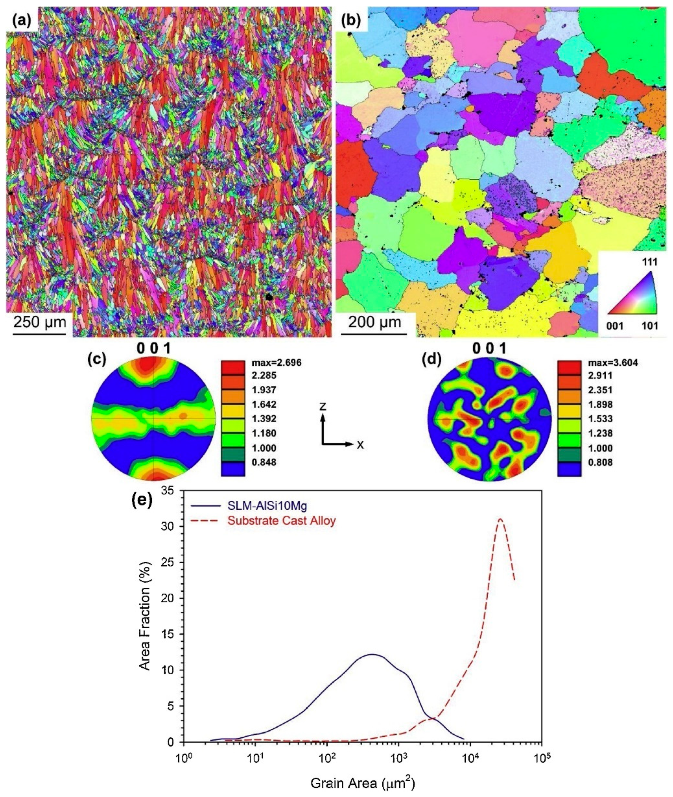
- Hadadzadeh, A.; Amirkhiz, B.S.; Shakerin, S.; Kelly, J.; Li, J.; Mohammadi, M. Microstructural investigation and mechanical behavior of a two-material component fabricated through selective laser melting of AlSi10Mg on an Al-Cu-Ni-Fe-Mg cast alloy substrate. Addit. Manuf. 2020, 31, 100937. [Google Scholar] [CrossRef]
- Kanagaraj, S.; Pattanayak, S. Measurement of the thermal expansion of metal and FRPs. Cryogenics 2003, 43, 399–424. [Google Scholar] [CrossRef]
- Wang, F.E. Chapter 2—Phase Equilibrium Diagrams. In Bonding Theory for Metals and Alloys, 2nd ed.; Wang, F.E., Ed.; Elsevier: Amsterdam, The Netherlands, 2019; pp. 5–41. [Google Scholar] [CrossRef]
- Springer, H.; Kostka, A.; Santos, J.F.D.; Raabe, D. Influence of intermetallic phases and Kirkendall-porosity on the mechanical properties of joints between steel and aluminium alloys. Mater. Sci. Eng. A 2011, 528, 4630–4642. [Google Scholar] [CrossRef]
- Bergh, T.; Arbo, S.; Hagen, A.; Blindheim, J.; Friis, J.; Khalid, M.; Ringdalen, I.; Holmestad, R.; Westermann, I.; Vullum, P. On intermetallic phases formed during interdiffusion between aluminium alloys and stainless steel. Intermetallics 2022, 142, 107443. [Google Scholar] [CrossRef]
- Chen, N.; Wang, M.; Wang, H.-P.; Wan, Z.; Carlson, B.E. Microstructural and mechanical evolution of Al/steel interface with Fe2Al5 growth in resistance spot welding of aluminum to steel. J. Manuf. Process 2018, 34, 424–434. [Google Scholar] [CrossRef]
- Borrisutthekul, R.; Yachi, T.; Miyashita, Y.; Mutoh, Y. Suppression of intermetallic reaction layer formation by controlling heat flow in dissimilar joining of steel and aluminum alloy. Mater. Sci. Eng. A 2007, 467, 108–113. [Google Scholar] [CrossRef]
- Hatano, R.; Ogura, T.; Matsuda, T.; Sano, T.; Hirose, A. Relationship between intermetallic compound layer thickness with deviation and interfacial strength for dissimilar joints of aluminum alloy and stainless steel. Mater. Sci. Eng. A 2018, 735, 361–366. [Google Scholar] [CrossRef]
- Massalski, T.B.; Murray, J.L.; Bennett, L.H.; Baker, H. Binary Alloy Phase Diagrams; American Society for Metals: Metals Park, OH, USA, 1986. [Google Scholar]
- Werner, M.R.; Fahrner, W.R. Review on Materials, Microsensors, Systems, and Devices for High-Temperature and Harsh-Environment Applications. IEEE Trans. Ind. Electron. 2001, 48, 249–257. [Google Scholar] [CrossRef]
- Toropova, M. Bimaterial Lattices with Anisotropic Thermal Expansion. J. Mech. Mater. Struct. 2014, 9, 227–244. [Google Scholar] [CrossRef]
- Yamamoto, N.; Gdoutos, E.; Toda, R.; White, V.; Manohara, H.; Daraio, C. Thin films with ultra-low thermal expansion. Adv. Mater. 2014, 26, 3076–3080. [Google Scholar] [CrossRef]
- Zweben, C. Advances in composite materials for thermal management in electronic packaging. JOM 1998, 50, 47–51. [Google Scholar] [CrossRef]
- Lu, D.D.; Wong, C.P. Materials for Advanced Packaging; Springer: New York, NY, USA, 2009. [Google Scholar] [CrossRef]
- Bartnitzek, T.; Thelemann, T.; Apel, S.; Suphan, K.-H. Advantages and Limitations of Ceramic Packaging Technologies in Harsh Applications. 2016. Available online: http://meridian.allenpress.com/ism/article-pdf/2016/1/000581/2253545/isom-2016-thp23.pdf (accessed on 10 November 2023).
- Ju, H.; Liu, S. Damage Degree analysis of storage failure modes for plastic encapsulated microelectronic devices. J. Phys. Conf. Ser. 2021, 2132, 12048. [Google Scholar] [CrossRef]
- Wan, Y.J.; Li, G.; Yao, Y.M.; Zeng, X.L.; Zhu, P.L.; Sun, R. Recent advances in polymer-based electronic packaging materials. Compos. Commun. 2020, 19, 154–167. [Google Scholar] [CrossRef]
- Lai, L.; Niu, B.; Bi, Y.; Li, Y.; Yang, Z. Advancements in SiC-Reinforced Metal Matrix Composites for High-Performance Electronic Packaging: A Review of Thermo-Mechanical Properties and Future Trends. Micromachines 2023, 14, 1491. [Google Scholar] [CrossRef]
- Tong, X.C. Electronic Packaging Materials and Their Functions in Thermal Managements. In Advanced Materials for Thermal Management of Electronic Packaging; Springer Series in Advanced Microelectronics; Springer Science and Business Media Deutschland GmbH: Berlin/Heidelberg, Germany, 2011; Volume 30, pp. 131–167. [Google Scholar] [CrossRef]
- Adachi, S. Handbook on Physical Properties of Semiconductors; Springer Science & Business Media: Berlin/Heidelberg, Germany, 2004. [Google Scholar]
- Gale, W.F.; Totemeier, T.C. (Eds.) 15—Elastic properties, damping capacity and shape memory alloys. In Smithells Metals Reference Book, 8th ed.; Butterworth-Heinemann: Oxford, UK, 2004; pp. 1–45. [Google Scholar] [CrossRef]
- Gale, W.F.; Totemeier, T.C. (Eds.) 14—General physical properties. In Smithells Metals Reference Book, 8th ed.; Butterworth-Heinemann: Oxford, UK, 2004; pp. 1–45. [Google Scholar] [CrossRef]
- Kim, J.C.; Ren, Z.; Yuksel, A.; Dede, E.M.; Bandaru, P.R.; Oh, D.; Lee, J. Recent Advances in Thermal Metamaterials and Their Future Applications for Electronics Packaging. J. Electron. Packag. Trans. ASME 2021, 143, 10801. [Google Scholar] [CrossRef]
- Vemuri, K.P.; Bandaru, P.R. An approach towards a perfect thermal diffuser. Sci. Rep. 2016, 6, 29649. [Google Scholar] [CrossRef]
- Narayana, S.; Sato, Y. Heat Flux Manipulation with Engineered Thermal Materials. Phys. Rev. Lett. 2012, 108, 214303. [Google Scholar] [CrossRef]
- Park, G.; Kang, S.; Lee, H.; Choi, W. Tunable multifunctional thermal metamaterials: Manipulation of local heat flux via assembly of unit-cell thermal shifters. Sci. Rep. 2017, 7, srep41000. [Google Scholar] [CrossRef] [PubMed]
- Singhal, S.C. Solid oxide fuel cells for power generation. WIREs Energy Environ. 2014, 3, 179–194. [Google Scholar] [CrossRef]
- Wee, J.H. Applications of proton exchange membrane fuel cell systems. Renew. Sustain. Energy Rev. 2007, 11, 1720–1738. [Google Scholar] [CrossRef]
- Ferriday, T.B.; Middleton, P.H. Alkaline fuel cell technology—A review. Int. J. Hydrogen Energy 2021, 46, 18489–18510. [Google Scholar] [CrossRef]
- Sammes, N.; Bove, R.; Stahl, K. Phosphoric acid fuel cells: Fundamentals and applications. Curr. Opin. Solid State Mater. Sci. 2004, 8, 372–378. [Google Scholar] [CrossRef]
- Contreras, R.R.; Almarza, J.; Rincón, L. Molten carbonate fuel cells: A technological perspective and review. In Energy Sources, Part A Recovery, Utilization and Environmental Effects; Taylor and Francis Ltd.: Abingdon, UK, 2021. [Google Scholar] [CrossRef]
- Hussain, S.; Yangping, L. Review of solid oxide fuel cell materials: Cathode, anode, and electrolyte. Energy Transit. 2020, 4, 113–126. [Google Scholar] [CrossRef]
- Golkhatmi, S.Z.; Asghar, M.I.; Lund, P.D. A review on solid oxide fuel cell durability: Latest progress, mechanisms, and study tools. Renew. Sustain. Energy Rev. 2022, 161, 112339. [Google Scholar] [CrossRef]
- Vishwanathan, A.S. Microbial fuel cells: A comprehensive review for beginners. 3 Biotech 2021, 11, 248. [Google Scholar] [CrossRef]
- Choudhury, A.; Chandra, H.; Arora, A. Application of solid oxide fuel cell technology for power generation—A review. Renew. Sustain. Energy Rev. 2013, 20, 430–442. [Google Scholar] [CrossRef]
- Minh, N.Q.; Takahashi, T. Chapter 6—Anode. In Science and Technology of Ceramic Fuel Cells; Minh, N.Q., Takahashi, T., Eds.; Elsevier Science Ltd: Oxford, UK, 1995; pp. 147–164. [Google Scholar] [CrossRef]
- Minh, N.Q.; Takahashi, T. Chapter 5—Cathode. In Science and Technology of Ceramic Fuel Cells; Minh, N.Q., Takahashi, T., Eds.; Elsevier Science Ltd: Oxford, UK, 1995; pp. 117–146. [Google Scholar] [CrossRef]
- Wu, J.; Liu, X. Recent Development of SOFC Metallic Interconnect. J. Mater. Sci. Technol. 2010, 26, 293–305. [Google Scholar] [CrossRef]
- Sakai, N.; Stølen, S. Heat capacity and thermodynamic properties of lanthanum(III) chromate(III): LaCrO3, at temperatures from 298.15 K. Evaluation of the thermal conductivity. J. Chem. Thermodyn. 1995, 27, 493–506. [Google Scholar] [CrossRef]
- Jiang, W.; Zhang, Y.; Woo, W.; Tu, S.T. Three-dimensional simulation to study the influence of foil thickness on residual stress in the bonded compliant seal design of planar solid oxide fuel cell. J. Power Sources 2012, 209, 65–71. [Google Scholar] [CrossRef]
- Marina, O.A.; Canfield, N.L.; Stevenson, J.W. Thermal, electrical, and electrocatalytical properties of lanthanum-doped strontium titanate. Solid State Ion. 2002, 149, 21–28. [Google Scholar] [CrossRef]
- Ullmann, H.; Trofimenko, N.; Tietz, F.; Stöver, D.; Ahmad-Khanlou, A. Correlation between thermal expansion and oxide ion transport in mixed conducting perovskite-type oxides for SOFC cathodes. Solid State Ion. 2000, 138, 79–90. [Google Scholar] [CrossRef]
- Abdin, Z.; Khalilpour, K.R. Chapter 4—Single and Polystorage Technologies for Renewable-Based Hybrid Energy Systems. In Polygeneration with Polystorage for Chemical and Energy Hubs; Khalilpour, K.R., Ed.; Academic Press: Cambridge, MA, USA, 2019; pp. 77–131. [Google Scholar] [CrossRef]
- Petric, A.; Huang, P.; Tietz, F. Evaluation of La–Sr–Co–Fe–O perovskites for solid oxide fuel cells and gas separation membranes. Solid State Ion. 2000, 135, 719–725. [Google Scholar] [CrossRef]
- Ni, Q.; Chen, H.; Ge, L.; Yu, S.; Guo, L. Investigation of La1−xSmx−ySryCoO3−δ cathode for intermediate temperature solid oxide fuel cells. J. Power Sources 2017, 349, 130–137. [Google Scholar] [CrossRef]
- Hayun, H.; Wolf, R.; Barad, C.; Gelbstein, Y. Thermal shock resistant solid oxide fuel cell ceramic composite electrolytes. J. Alloys Compd. 2020, 821, 153490. [Google Scholar] [CrossRef]
- Zhang, Y.; Chen, B.; Guan, D.; Xu, M.; Ran, R.; Ni, M.; Zhou, W.; O’Hayre, R.; Shao, Z. Thermal-expansion offset for high-performance fuel cell cathodes. Nature 2021, 591, 246–251. [Google Scholar] [CrossRef]
- Zhou, W.; Shao, Z.; Ran, R.; Cai, R. Novel SrSc0.2Co0.8O3-δ as a cathode material for low temperature solid-oxide fuel cell. Electrochem. Commun. 2008, 10, 1647–1651. [Google Scholar] [CrossRef]
- Zhou, W.; Ran, R.; Shao, Z.; Jin, W.; Xu, N. Evaluation of A-site cation-deficient (Ba0.5Sr0.5)1-xCo0.8Fe0.2O3-δ (x > 0) perovskite as a solid-oxide fuel cell cathode. J. Power Sources 2008, 182, 24–31. [Google Scholar] [CrossRef]
- Ding, X.; Cui, C.; Guo, L. Thermal expansion and electrochemical performance of La0.7Sr0.3CuO3-δ-Sm0.2Ce0.8O2-δ composite cathode for IT-SOFCs. J. Alloys Compd. 2009, 481, 845–850. [Google Scholar] [CrossRef]
- Song, Y.; Chen, Y.; Xu, M.; Wang, W.; Zhang, Y.; Yang, G.; Ran, R.; Zhou, W.; Shao, Z. A Cobalt-Free Multi-Phase Nanocomposite as Near-Ideal Cathode of Intermediate-Temperature Solid Oxide Fuel Cells Developed by Smart Self-Assembly. Adv. Mater. 2020, 32, e1906979. [Google Scholar] [CrossRef] [PubMed]
- Jia, X.; Lu, F.; Liu, K.; Han, M.; Su, J.; He, H.; Cai, B. Improved performance of IT-SOFC by negative thermal expansion Sm0.85Zn0.15MnO3 addition in Ba0.5Sr0.5Fe0.8Cu0.1Ti0.1O3-δcathode. J. Phys. Cond. Matter 2022, 34, 184001. [Google Scholar] [CrossRef]
- Minh, N.Q. Ceramic Fuel Cells. J. Am. Ceram. Soc. 1993, 76, 563–588. [Google Scholar] [CrossRef]
- Fergus, J.W. Metallic interconnects for solid oxide fuel cells. Mater. Sci. Eng. A 2005, 397, 271–283. [Google Scholar] [CrossRef]
- Hodjati-Pugh, O.; Dhir, A.; Steinberger-Wilckens, R. The development of current collection in micro-tubular solid oxide fuel cells—A review. Appl. Sci. 2021, 11, 1077. [Google Scholar] [CrossRef]
- Niewolak, L.; Tietz, F.; Quadakkers, W.J. Interconnects. In High-Temperature Solid Oxide Fuel Cells for the 21st Century: Fundamentals, Design and Applications; Elsevier: Amsterdam, The Netherlands, 2015; pp. 195–254. [Google Scholar] [CrossRef]
- Horita, T.; Xiong, Y.; Kishimoto, H.; Yamaji, K.; Brito, M.E.; Yokokawa, H. Chromium Poisoning and Degradation at (La,Sr)MnO3 and (La,Sr)FeO3 Cathodes for Solid Oxide Fuel Cells. J. Electrochem. Soc. 2010, 157, B614. [Google Scholar] [CrossRef]
- Yang, Z.; Weil, K.S.; Paxton, D.M.; Stevenson, J.W. Selection and Evaluation of Heat-Resistant Alloys for SOFC Interconnect Applications. J. Electrochem. Soc. 2003, 150, A1188. [Google Scholar] [CrossRef]
- Kofstad, P.; Bredesen, R. High temperature corrosion in SOFC environments. Solid State Ion. 1992, 52, 69–75. [Google Scholar] [CrossRef]
- Yang, Z.; Xia, G.G.; Stevenson, J.W. Evaluation of Ni-Cr-base alloys for SOFC interconnect applications. J. Power Sources 2006, 160, 1104–1110. [Google Scholar] [CrossRef]
- Zohrabian, V.M.; Sonick, M.; Hwang, D.; Abrahams, J.J. Dental Implants. Semin. Ultrasound CT MRI 2015, 36, 415–426. [Google Scholar] [CrossRef]
- Hao, C.P.; Cao, N.J.; Zhu, Y.H.; Wang, W. The osseointegration and stability of dental implants with different surface treatments in animal models: A network meta-analysis. Sci. Rep. 2021, 11, 13849. [Google Scholar] [CrossRef]
- Panchal, M.; Khare, S.; Khamkar, P.; Bhole, K.S. Dental implants: A review of types, design analysis, materials, additive manufacturing methods, and future scope. Mater. Today Proc. 2022, 68, 1860–1867. [Google Scholar] [CrossRef]
- Nicholson, J.W. Titanium Alloys for Dental Implants: A Review. Prosthesis 2020, 2, 100–116. [Google Scholar] [CrossRef]
- Prathapachandran, J.; Suresh, N. Management of peri-implantitis. Dent. Res. J. 2012, 9, 516. [Google Scholar]
- Noyama, Y.; Miura, T.; Ishimoto, T.; Itaya, T.; Niinomi, M.; Nakano, T. Bone loss and reduced bone quality of the human femur after total hip arthroplasty under stress-shielding effects by titanium-based implant. Mater. Trans. 2012, 53, 565–570. [Google Scholar] [CrossRef]
- Niu, L.; Dong, S.J.; Kong, T.T.; Wang, R.; Zou, R.; Da Liu, Q. Heat transfer behavior across the dentino-enamel junction in the human tooth. PLoS ONE 2016, 11, e0158233. [Google Scholar] [CrossRef]
- Jacobs, H.R.; Thompson, R.E.; Brown, W.S. Heat Transfer in Teeth. J. Dent. Res. 1973, 52, 248–252. [Google Scholar] [CrossRef]
- Li, S.; Chien, S.; Brånemark, P.I. Heat shock-induced necrosis and apoptosis in osteoblasts. J. Orthop. Res. 1999, 17, 891–899. [Google Scholar] [CrossRef]
- Eriksson, A.R.; Albrektsson, T. Temperature threshold levels for heat-induced bone tissue injury: A vital-microscopic study in the rabbit. J. Prosthet. Dent. 1983, 50, 101–107. [Google Scholar] [CrossRef]
- Ormianer, Z.; Feuerstein, O.; Assad, R.; Samet, N.; Weiss, E.I. In vivo changes in dental implant temperatures during hot beverage intake: A pilot study. Implant Dent. 2009, 18, 38–45. [Google Scholar] [CrossRef]
- Froes, F.; Gungor, M.N.; Imam, M.A. Overview Titanium’s Expanding Market Cost-Affordable Titanium: The Component Fabrication Perspective. JOM 2007, 59, 28–31. [Google Scholar] [CrossRef]
- Anderson, B.J.; Justus, C.G.; Batts, G.W. Guidelines for the Selection of Near-Earth Thermal Environment Parameters for Spacecraft Design. 2001. Available online: http://www.sti.nasa.gov (accessed on 15 November 2023).
- Ghidini, T. Materials for space exploration and settlement. Nat. Mater. 2018, 17, 846–850. [Google Scholar] [CrossRef] [PubMed]
- Lu, G.Y.; Zhou, J.Y.; Cai, G.P.; Fang, G.Q.; Lv, L.L.; Peng, F.J. Studies of thermal deformation and shape control of a space planar phased array antenna. Aerosp. Sci. Technol. 2019, 93, 105311. [Google Scholar] [CrossRef]
- Bhundiya, H.G.; Royer, F.; Cordero, Z. Engineering Framework for Assessing Materials and Processes for In-Space Manufacturing. J. Mater. Eng. Perform. 2022, 31, 6045–6059. [Google Scholar] [CrossRef]
- Yu, B.; Xu, Z.; Mu, R.; Wang, A.; Zhao, H. Design of Large-Scale Space Lattice Structure with Near-Zero Thermal Expansion Metamaterials. Aerospace 2023, 10, 294. [Google Scholar] [CrossRef]
- Milward, S.S. Controlling Thermal Expansion with Lattice Structures Using Laser Powder Bed Fusion Laser Powder Bed Fusion Process Development. 2017. Available online: http://www.swansea.ac.uk/library/researchsupport/ris-support/ (accessed on 18 November 2023).


| Classification | Design | Researchers | Constituent Materials | CTE (×10−6 m/m°C) | Type of Analysis | Fabrication Method | Ref. |
|---|---|---|---|---|---|---|---|
| Bending-based architectures | |||||||
| Bimaterial-Strip-based | Single bimaterial strip | Lakes et al. | - | Unbounded | Analytical | - | [12] |
| Honeycomb lattice using bimaterial strip | Lakes et al. | Steel, invar | −103 to 103 | Analytical | - | [13] | |
| Triangular lattice using bimaterial strip | Lehman et al. | Steel, invar | Zero, tuneable as negative or positive | Analytical | - | [14] | |
| Triangular and square lattices using bimaterial strip | Ha et al. | Steel, invar | Triangular lattice: −0.03 to 6.67; Square lattice: Zero | Computational | - | [36] | |
| Multilayered strip (three or more layers) | Grima et al. | Polyvinylidene chloride, silicone rubber | Zero to -ve values (tuneable) | Analytical, Computational | - | [19] | |
| Chirality-based | 2D triangular chiral lattice | Ha et al. | Alloy 1 (72%Mn, 18%Cu, 10%Ni), Alloy 2 (invar) | −350 | Experimental | Bonding glue: Loctite type 491 cement | [16] |
| 2D anti-tetrachiral and trichiral lattices, 3D anti-tetrachiral lattice | Wu et al. | 2D lattices: Aluminium, copper; 3D lattice: VeroWhitePlus RGD835 and TangoPlus FLX930 polymers | 2D anti-tetrachiral: −70 to −35; 2D anti-trichiral: −45 to zero; 3D anti-tetrachiral: −700 to −100 | Computational, Experimental | 2D lattices: Screwed fittings; 3D lattice: Multimaterial polymer 3D printing (Objet350 connex2, Stratasys Ltd., Eden Prairie, MN, USA) | [20] | |
| Re-entrant-based | Re-entrant cell-based four different 2D lattices | Ai et al. | Aluminium, steel, and invar (any two constituents per lattice) | −41 to 14.4 (Highly tuneable) | Computational | - | [26] |
| Basic re-entrant unit cell lattice | Raminhos et al. | Two combinations: Nylon, Polyvinyl alcohol compound (PVA); Polypropylene (PP), Copolyester (CPE+) | −1568 to 498 in different combinations | Experimental | Fused filament fabrication 3D printing (Ultimaker 3TM) | [27] | |
| Modified re-entrant unit cell-based 2D and 3D lattices | Peng et al. | Al6061, invar | −75 to 23 for 2D; −368 to 575 for 3D; Tuneable | Analytical, Computational | - | [34,35] | |
| Other bending-based designs | Hexagonal grid-shaped lattice | Jefferson et al. | - | Tuneable | Analytical, Computational | - | [24] |
| X-shaped 2D lattice | Lim et al. | - | Tuneable | Analytical | - | [37] | |
| Stretch-based architectures | |||||||
| Triangle-based | 2D triangular lattice | Grima et al. | - | Tuneable as +ve, zero or −ve | Analytical | - | [17] |
| Triangular lattice with inscribed triangles | Steeves et al. | Al7075-T6, Ti6Al4V | 0 to 42 | Analytical, Computational, Experimental | Laser cutting from sheets, assembly using Brazing/laser welding | [21] | |
| 2D Hexagonal lattices | Wei et al. | Al7075, SS431, invar (Any two in one lattice) | Al–invar: −5 to Zero; Al-SS: 30; Tuneable | Analytical, Experimental | Electric discharge machining of members from sheets; Interference fit assembly using grooves | [22] | |
| Hoberman-sphere-inspired lattice | Li et al. | Elastomer, glassy polymer | −1040 to 10 | Analytical, Computational, Experimental | Multimaterial polymer 3D printing (Objet260 Connex, Stratasys Ltd.) | [23] | |
| Tetrahedron-based | Tetrahedral lattice | Lim et al. | - | Tuneable | Analytical | - | [29] |
| Tetrahedral lattices: Stationary/non-stationary concept-based line | Xu et al. | Al6061, Ti6Al4V, invar (Al6061–Ti6Al4V and Al6061–invar combinations) | −35 to 10, Tuneable | Analytical, Computational, Experimental | Pin-jointed interference fit metallic bars bonded using epoxy glue | [31] | |
| Octahedron-based | Cubic cell | Jin et al. | - | Tuneable +ve, zero or −ve | Analytical | - | [32] |
| Octet lattice | Xu et al. | Al6061, Ti6Al4V | Aniso-octet design: −366 to 10.9; Iso-octet design: 0.273 to 11.3 | Computational, Experimental | Pretension snap-fitting of laser-cut members using epoxy glue | [30] | |
| Other designs | Ring rod sliding structure | Lim et al. | - | Tuneable as +ve, zero or −ve | Analytical | - | [28] |
| Lattice-based machine frame design | Juasiripukdee et al. | Nylon 12, Ultra-high-molecular-weight polyethylene (UHMWPE) | 0.001 | Computational, Experimental | Nylon 12 outer part used polymer LPBF; Inner UHMWPE part used conventional manufacturing | [33] | |
| Type of Packaging Material | Advantages | Limitations | References |
|---|---|---|---|
| Ceramic | Low CTE, low density | Low TC | [232,233] |
| Plastic | Small size, light weight, high impact resistance | Low TC caused by internal voids, easily corroded | [234,235] |
| Metal | High TC | High CTE leading to increased thermal stresses | [236,237] |
| Type of Fuel Cell | Common Electrolyte | Operating Temperature | Efficiency | Applications | References |
|---|---|---|---|---|---|
| Proton Exchange Membrane (PEM) | Perfluoro sulfonic acid | 50–100 °C | 60% | Portable power, automobiles, backup power | [246] |
| Alkaline (AFC) | Aqueous potassium hydroxide in a matrix | 90–100 °C | 60% | Military, space | [247] |
| Phosphoric Acid (PAFC) | Phosphoric acid in a matrix | 150–200 °C | 40% | Distributed generation | [248] |
| Molten Carbonate (MCFC) | Lithium, sodium and/or potassium carbonates | 600–700 °C | 45–50% | Distributed generation | [249] |
| Solid Oxide (SOFC) | Yttria stabilized zirconia | 700–1000 °C | 60% | Auxiliary power, Electric utility, Distributed generation | [250,251] |
| Microbial Fuel Cell | Microbes | Ambient temperature | 50% | Carbon capture, Wastewater treatment, Biowaste energy recovery | [252,253] |
| Anode | CTE (×10−6 K−1) | Electrolyte | CTE (×10−6 K−1) | Cathode | CTE (×10−6 K−1) | Interconnect | CTE (×10−6 K−1) | Seals | CTE (×10−6 K−1) |
|---|---|---|---|---|---|---|---|---|---|
| Ni-YSZ | 12.2 [254] | YSZ | 12.9 | LSM | 11.7 [255] | LaCrO3 | 9.7 [256,257] | Ag-Cuo | 15.0 [258] |
| LST | 10.8 [259] | LSF | 16.3 [260] | Soda glass | 9.0 [261] | ||||
| SLC | 8.6–11.5 | LSC | 20.5 [260] | ||||||
| LSCF | 16.3 [260] | ||||||||
| LSMF | 19.3 [262] | ||||||||
| SSC | 19.9 [263] | ||||||||
| PSM | 11.6 [260] |
Disclaimer/Publisher’s Note: The statements, opinions and data contained in all publications are solely those of the individual author(s) and contributor(s) and not of MDPI and/or the editor(s). MDPI and/or the editor(s) disclaim responsibility for any injury to people or property resulting from any ideas, methods, instructions or products referred to in the content. |
© 2024 by the authors. Licensee MDPI, Basel, Switzerland. This article is an open access article distributed under the terms and conditions of the Creative Commons Attribution (CC BY) license (https://creativecommons.org/licenses/by/4.0/).
Share and Cite
Dubey, D.; Mirhakimi, A.S.; Elbestawi, M.A. Negative Thermal Expansion Metamaterials: A Review of Design, Fabrication, and Applications. J. Manuf. Mater. Process. 2024, 8, 40. https://doi.org/10.3390/jmmp8010040
Dubey D, Mirhakimi AS, Elbestawi MA. Negative Thermal Expansion Metamaterials: A Review of Design, Fabrication, and Applications. Journal of Manufacturing and Materials Processing. 2024; 8(1):40. https://doi.org/10.3390/jmmp8010040
Chicago/Turabian StyleDubey, Devashish, Anooshe Sadat Mirhakimi, and Mohamed A. Elbestawi. 2024. "Negative Thermal Expansion Metamaterials: A Review of Design, Fabrication, and Applications" Journal of Manufacturing and Materials Processing 8, no. 1: 40. https://doi.org/10.3390/jmmp8010040
APA StyleDubey, D., Mirhakimi, A. S., & Elbestawi, M. A. (2024). Negative Thermal Expansion Metamaterials: A Review of Design, Fabrication, and Applications. Journal of Manufacturing and Materials Processing, 8(1), 40. https://doi.org/10.3390/jmmp8010040