
Phase Composition, Microstructure and Mechanical Properties of Zr57Cu15Ni10Nb5 Alloy Obtained by Selective Laser Melting

 ,
,  ,
,
Abstract
1. Introduction
2. Materials and Methods
2.1. Materials
2.2. SLM
2.3. Characterization
3. Results
3.1. Microstructure and Phase Composition
3.2. Mechanical and Tribological Properties
4. Discussion
5. Conclusions
- Within this study, multilayered SLM specimens from Vit-106 were obtained, their microstructure was investigated, and their microhardness and tribological behavior were tested.
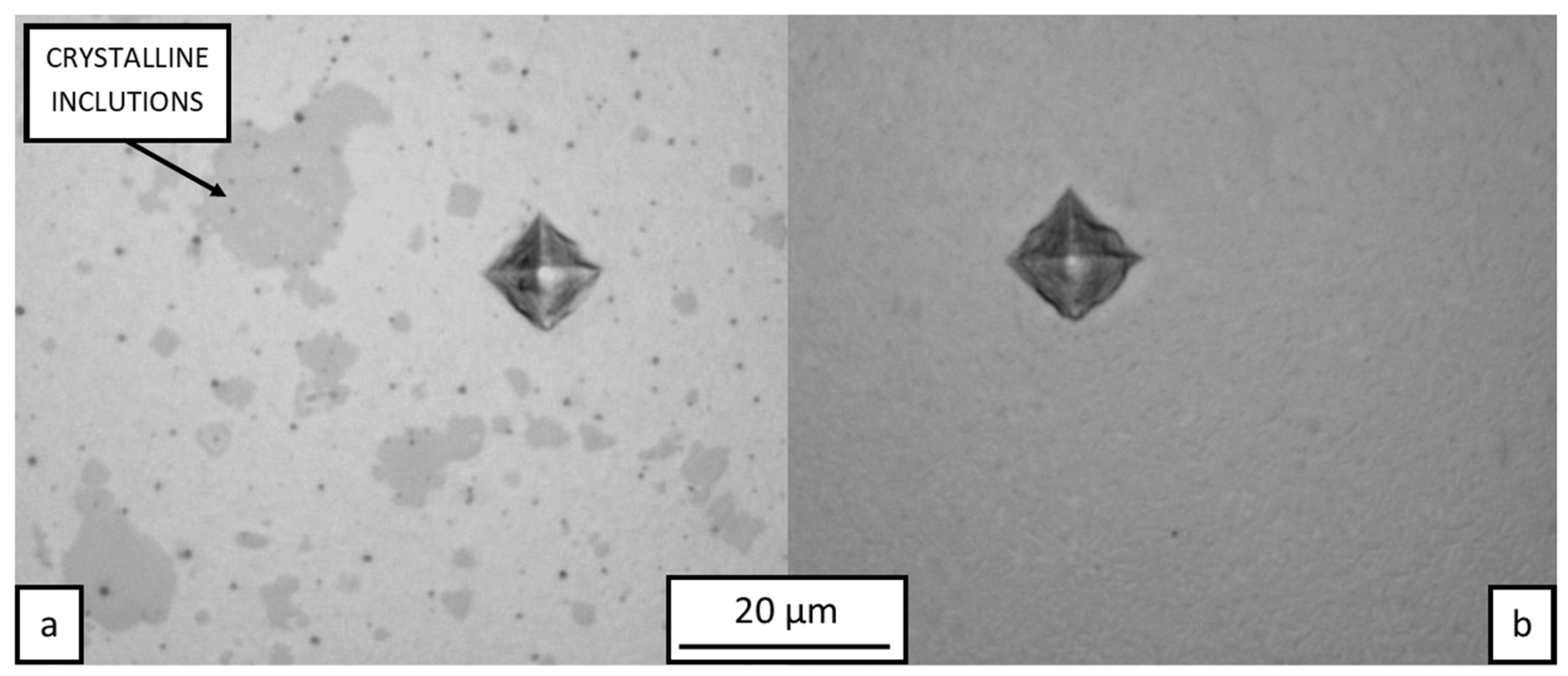
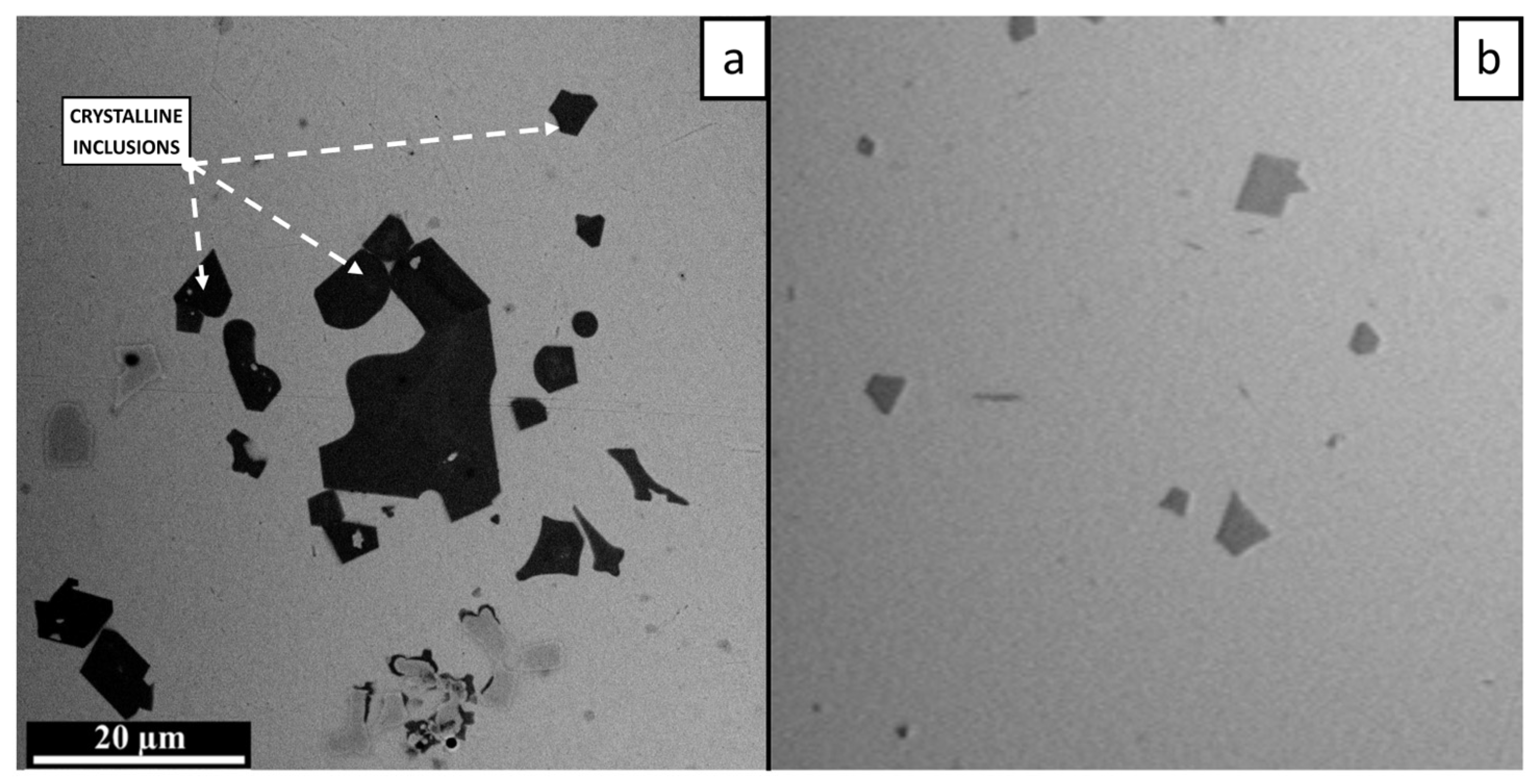
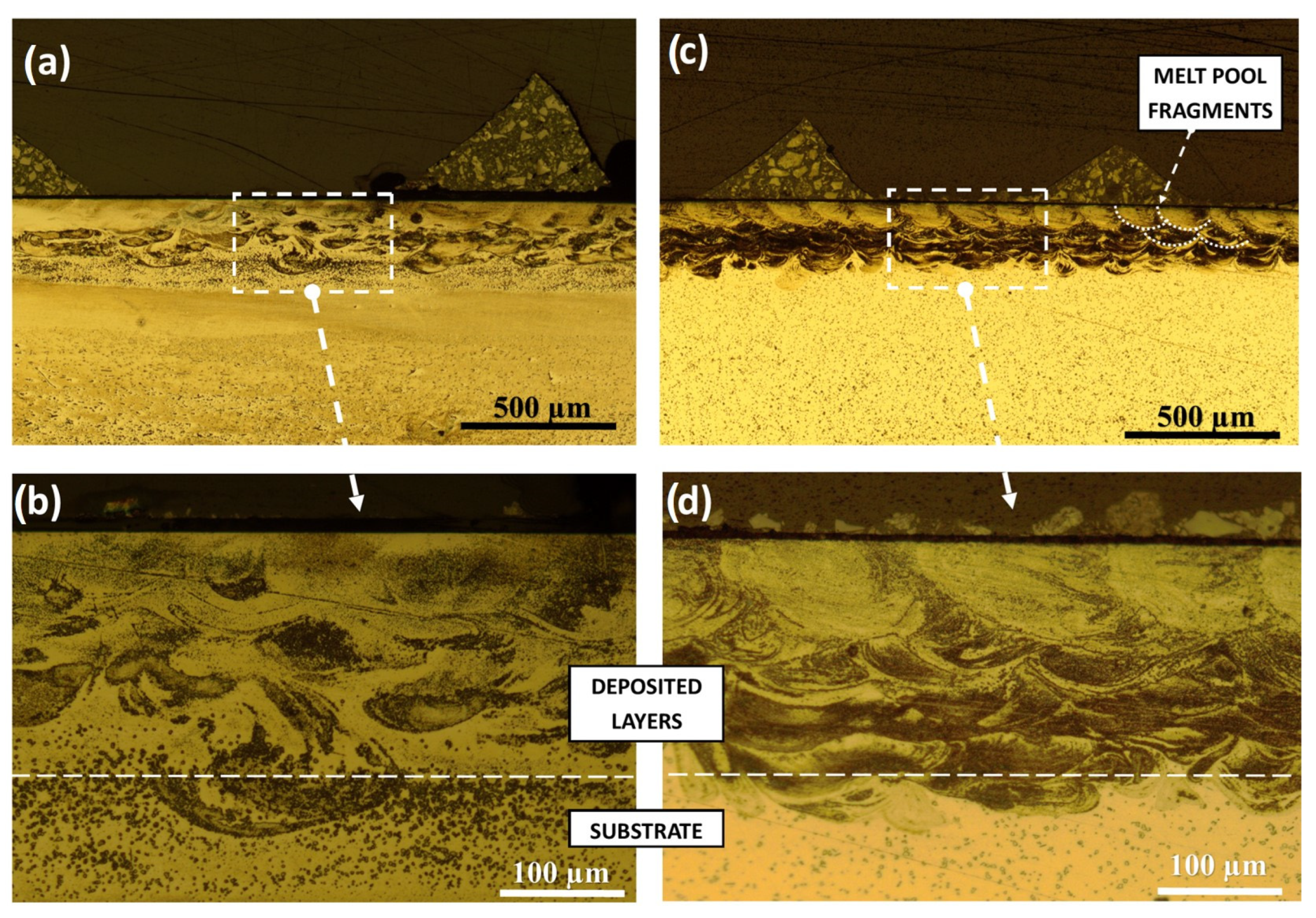
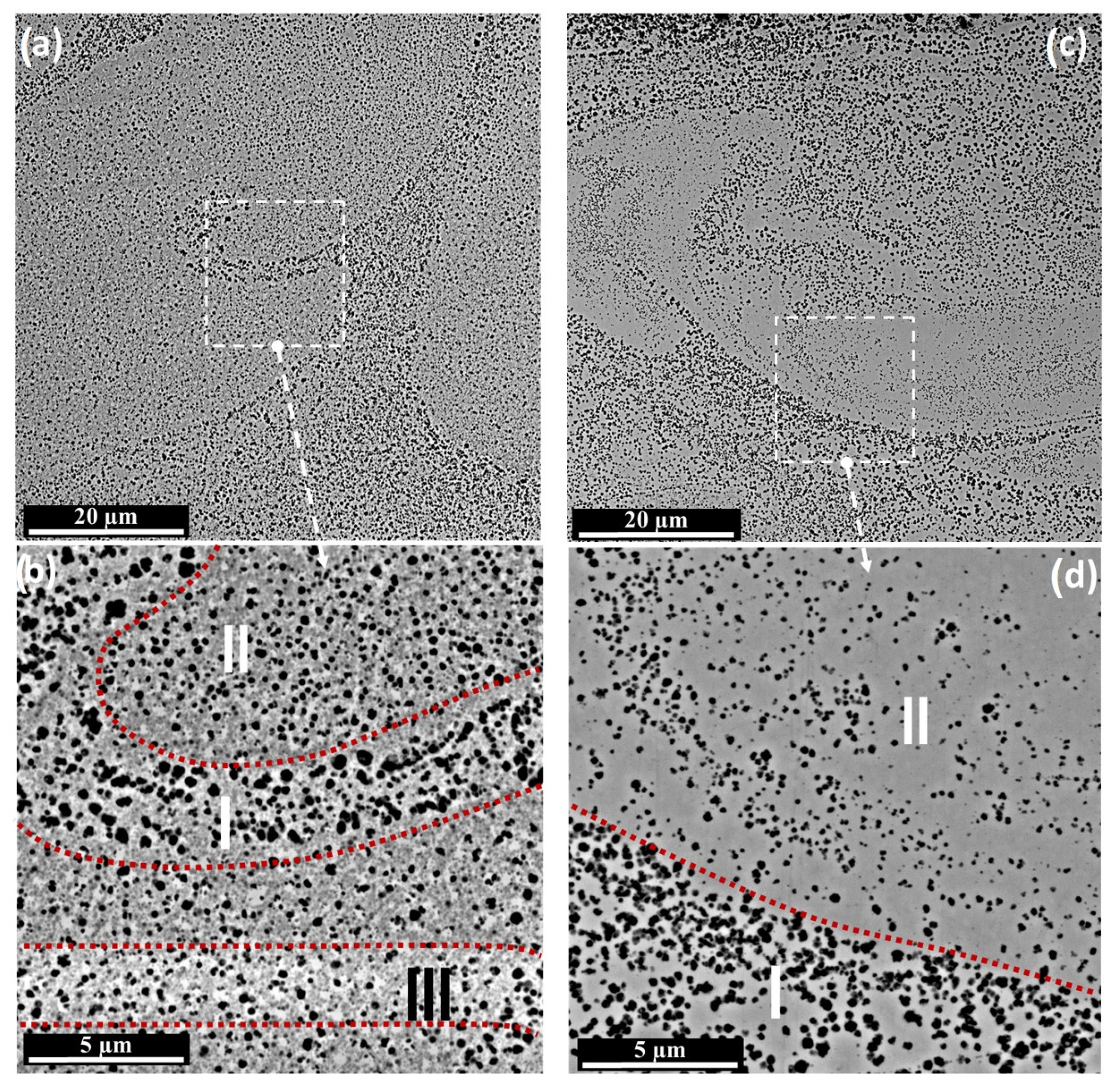
- The SLM specimens consisted of an amorphous matrix with two types of crystalline inclusions. Submicron CuZr2 particles were found in the remelted vortex structure, while coarser CuZr2 of up to 20 µm were observed in the heat-affected zone of the substrate. The nature of the distribution of submicron inclusions shows that they can grow from oxide nuclei transported by convection in the melt pool.
- Large crystals in the thermally affected zone are most likely formed during the growth of intermetallic inclusions initially contained in the substrate material.
- Submicron crystalline inclusions increase wear resistance and can increase microhardness. The role of oxygen in the formation of the amorphous–crystalline structure, as well as the influence of structural parameters on mechanical properties requires further research.
Author Contributions
Funding
Data Availability Statement
Acknowledgments
Conflicts of Interest
References
- Schuh, C.; Hufnagel, T.; Ramamurty, U. Mechanical Behavior of Amorphous Alloys. Acta Mater. 2007, 55, 4067–4109. [Google Scholar] [CrossRef]
- Greer, A.L. Metallic Glasses…on the Threshold. Mater. Today 2009, 12, 14–22. [Google Scholar] [CrossRef]
- Kruzic, J.J. Bulk Metallic Glasses as Structural Materials: A Review. Adv. Eng. Mater. 2016, 18, 1308–1331. [Google Scholar] [CrossRef]
- Liquidmetal: Amorphous Metal Alloys. Available online: https://liquidmetal.com/ (accessed on 9 November 2023).
- Deng, L.; Gebert, A.; Zhang, L.; Chen, H.Y.; Gu, D.D.; Kühn, U.; Zimmermann, M.; Kosiba, K.; Pauly, S. Mechanical Performance and Corrosion Behaviour of Zr-Based Bulk Metallic Glass Produced by Selective Laser Melting. Mater. Des. 2020, 189, 108532. [Google Scholar] [CrossRef]
- Marattukalam, J.J.; Pacheco, V.; Karlsson, D.; Riekehr, L.; Lindwall, J.; Forsberg, F.; Jansson, U.; Sahlberg, M.; Hjörvarsson, B. Development of Process Parameters for Selective Laser Melting of a ZR-Based Bulk Metallic Glass. Addit. Manuf. 2020, 33, 101124. [Google Scholar] [CrossRef]
- Lindwall, J.; Pacheco, V.; Sahlberg, M.; Lundbäck, A.; Lindgren, L.-E. Thermal Simulation and Phase Modeling of Bulk Metallic Glass in the Powder Bed Fusion Process. Addit. Manuf. 2019, 27, 345–352. [Google Scholar] [CrossRef]
- Jiang, Q.; Liu, H.; Li, J.; Yang, D.; Zhang, Y.; Yang, W. Atomic-Level Understanding of Crystallization in the Selective Laser Melting of FE50NI50 Amorphous Alloy. Addit. Manuf. 2020, 34, 101369. [Google Scholar] [CrossRef]
- Bacheeva, A.V.; Khmyrov, R.S.; Korotkov, A.D.; Tarasova, T.V.; Gusarov, A.V. Amorphous-Crystalline Composite Microstructure Formation in Zr46Cu46al8 Alloy at the Conditions of Selective Laser Melting. Key Eng. Mater. 2022, 910, 959–965. [Google Scholar] [CrossRef]
- Pérez-Ruiz, J.D.; Marin, F.; Martínez, S.; Lamikiz, A.; Urbikain, G.; López de Lacalle, L.N. Stiffening Near-Net-Shape Functional Parts of Inconel 718 LPBF Considering Material Anisotropy and Subsequent Machining Issues. Mech. Syst. Sign. Proc. 2022, 168, 108675. [Google Scholar] [CrossRef]
- Ouyang, D.; Xing, W.; Li, N.; Li, Y.; Liu, L. Structural Evolutions in 3D-Printed FE-Based Metallic Glass Fabricated by Selective Laser Melting. Addit. Manuf. 2018, 23, 246–252. [Google Scholar] [CrossRef]
- Yang, G.; Lin, X.; Liu, F.; Hu, Q.; Ma, L.; Li, J.; Huang, W. Laser Solid Forming ZR-Based Bulk Metallic Glass. Intermetallics 2012, 22, 110–115. [Google Scholar] [CrossRef]
- Zhang, Y.; Lin, X.; Wang, L.; Wei, L.; Liu, F.; Huang, W. Microstructural Analysis of ZR55CU30AL10NI5 Bulk Metallic Glasses by Laser Surface Remelting and Laser Solid Forming. Intermetallics 2015, 66, 22–30. [Google Scholar] [CrossRef]
- Li, X.P.; Kang, C.W.; Huang, H.; Zhang, L.C.; Sercombe, T.B. Selective Laser Melting of an Al86ni6y4.5co2la1.5 Metallic Glass: Processing, Microstructure Evolution and Mechanical Properties. Mater. Sci. Eng. A 2014, 606, 370–379. [Google Scholar] [CrossRef]
- Li, X.P.; Roberts, M.P.; O’Keeffe, S.; Sercombe, T.B. Selective Laser Melting of ZR-Based Bulk Metallic Glasses: Processing, Microstructure and Mechanical Properties. Mater. Des. 2016, 112, 217–226. [Google Scholar] [CrossRef]
- Li, N.; Zhang, J.; Xing, W.; Ouyang, D.; Liu, L. 3D Printing of Fe-Based Bulk Metallic Glass Composites with Combined High Strength and Fracture Toughness. Mater. Des. 2018, 143, 285–296. [Google Scholar] [CrossRef]
- Shao, L.; Ketkaew, J.; Gong, P.; Zhao, S.; Sohn, S.; Bordeenithikasem, P.; Datye, A.; Mota, R.M.; Liu, N.; Kube, S.A.; et al. Effect of Chemical Composition on the Fracture Toughness of Bulk Metallic Glasses. Materialia 2020, 12, 100828. [Google Scholar] [CrossRef]
- Fracture Toughness. Available online: https://en.wikipedia.org/wiki/Fracture_toughness (accessed on 19 December 2023).
- Pauly, S.; Schricker, C.; Scudino, S.; Deng, L.; Kühn, U. Processing a Glass-Forming ZR-Based Alloy by Selective Laser Melting. Mater. Des. 2017, 135, 133–141. [Google Scholar] [CrossRef]
- Bordeenithikasem, P.; Stolpe, M.; Elsen, A.; Hofmann, D.C. Glass Forming Ability, Flexural Strength, and Wear Properties of Additively Manufactured ZR-Based Bulk Metallic Glasses Produced through Laser Powder Bed Fusion. Addit. Manuf. 2018, 21, 312–317. [Google Scholar] [CrossRef]
- Best, J.P.; Ostergaard, H.E.; Li, B.; Stolpe, M.; Yang, F.; Nomoto, K.; Hasib, M.T.; Muránsky, O.; Busch, R.; Li, X.; et al. Fracture and Fatigue Behaviour of a Laser Additive Manufactured ZR-Based Bulk Metallic Glass. Addit. Manuf. 2020, 36, 101416. [Google Scholar] [CrossRef]
- Best, J.P.; Ast, J.; Li, B.; Stolpe, M.; Busch, R.; Yang, F.; Li, X.; Michler, J.; Kruzic, J.J. Relating Fracture Toughness to Micro-Pillar Compression Response for a Laser Powder Bed Additive Manufactured Bulk Metallic Glass. Mater. Sci. Eng. A 2020, 770, 138535. [Google Scholar] [CrossRef]
- Hays, C.C.; Kim, C.P.; Johnson, W.L. Large Supercooled Liquid Region and Phase Separation in the Zr–Ti–Ni–Cu–Be Bulk Metallic Glasses. Appl. Phys. Lett. 1999, 75, 1089–1091. [Google Scholar] [CrossRef]
- Dong, W.; Zhang, H.; Sun, W.; Ding, B.; Hu, Z. Formation, Thermal Stability and Mechanical Properties of Zr-Nb-Cu-Ni-Al Bulk Metallic Glasses. Mater. Trans. 2006, 47, 1294–1298. [Google Scholar] [CrossRef]
- The Online Materials Information Resource. Available online: http://www.matweb.com/search/datasheet.aspx?matguid=5c9ee48e2a704449b5880173789349cb&ckck=1 (accessed on 8 December 2023).
- Khmyrov, R.S.; Podrabinnik, P.A.; Tarasova, T.V.; Gridnev, M.A.; Korotkov, A.D.; Grigoriev, S.N.; Kurmysheva, A.Y.; Kovalev, O.B.; Gusarov, A.V. Partial Crystallization in a Zr-Based Bulk Metallic Glass in Selective Laser Melting. Int. J. Adv. Manuf. Technol. 2023, 126, 5613–5631. [Google Scholar] [CrossRef]
- Shelekhov, E.V.; Sviridova, T.A. Programs for X-Ray Analysis of Polycrystals. Metal Sci. Heat Treat 2000, 42, 309–313. [Google Scholar] [CrossRef]
- Gražulis, S.; Chateigner, D.; Downs, R.T.; Yokochi, A.F.; Quirós, M.; Lutterotti, L.; Manakova, E.; Butkus, J.; Moeck, P.; Le Bail, A. Crystallography Open Database—An Open-Access Collection of Crystal Structures. J. Appl. Cryst. 2009, 42, 726–729. [Google Scholar] [CrossRef] [PubMed]
- Grigoriev, S.N.; Khmyrov, R.S.; Gridnev, M.A.; Tarasova, T.V.; Gusarov, A.V. Optimizing the Process Parameters for Additive Manufacturing of Glass Components by Selective Laser Melting: Soda-Lime Glass versus Quartz Glass. J. Manuf. Sci. Eng. 2021, 144, 064503. [Google Scholar] [CrossRef]
- Gridnev, M.; Khmyrov, R.S. Model of Heat Transfer and Crystallization Kinetics in the Heat-Affected Zone in VIT 106 Alloy in Selective Laser Melting. High Temp. Mater. Process. 2023, 28, 9–18. [Google Scholar] [CrossRef]
- Yang, Z.; Al-Mukadam, R.; Stolpe, M.; Markl, M.; Deubener, J.; Körner, C. Isothermal Crystallization Kinetics of an Industrial-Grade ZR-Based Bulk Metallic Glass. J. Non-Cryst. Solids. 2021, 573, 121145. [Google Scholar] [CrossRef]
- Shadowspeaker, L.; Shah, M.; Busch, R. On the Crystalline Equilibrium Phases of the Zr57cu15.4ni12.6al10nb5 Bulk Metallic Glass Forming Alloy. Scr. Mater. 2004, 50, 1035–1038. [Google Scholar] [CrossRef]


| Zr, % | Ti, % | Cu, % | Be, % | Ni, % | Nb, % | Al, % | Glass Transition Temperature, K | Crystallization Temperature, K | Melting Point, K | Ref. | |
|---|---|---|---|---|---|---|---|---|---|---|---|
| Vit 1 | 41.2 | 13.8 | 12.5 | 22.5 | 0 | 0 | 0 | 625 | 705 | 930 | [23] |
| Vit 106 | 57 | 0 | 15.4 | 0 | 12.6 | 5 | 10 | 672 | 738 | 1092 | [24] |
| Vit 106a | 58.5 | 0 | 15.6 | 0 | 12.8 | 2.8 | 10.3 | 668 | 772 | 1110 | [25] |
| AMZ 4 | 59.3 | 0 | 28.8 | 0 | 0 | 1.5 | 10.4 | 673 | 743 | 1203 | [6] |
| No. | Specimen | Description |
|---|---|---|
| 1 | Amorphous plate | As-received |
| 2 | Amorphous plate | Ground plates to remove defect surface layers |
| 3 | Crystalline plate | Plate annealed at 700 °C for 2 h in vacuum with 10 K/min heating and cooling rate |
| 4 | Multilayered SLM | P = 160 W, V = 350 mm/s, S = 185 µm, H = 70 µm, 5 layers |
| 5 | Multilayered SLM | P = 160 W, V = 700 mm/s, S = 125 µm, H = 70 µm, 5 layers |
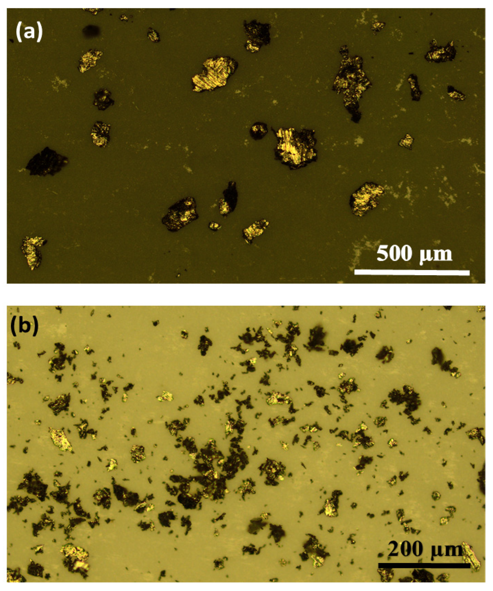
| Ball milling time, min | 35 | 50 | 75 | 100 |
| Average particle size, µm | 156 | 103 | 85 | 51 |
| Standard deviation, µm | 77 | 46 | 32 | 20 |
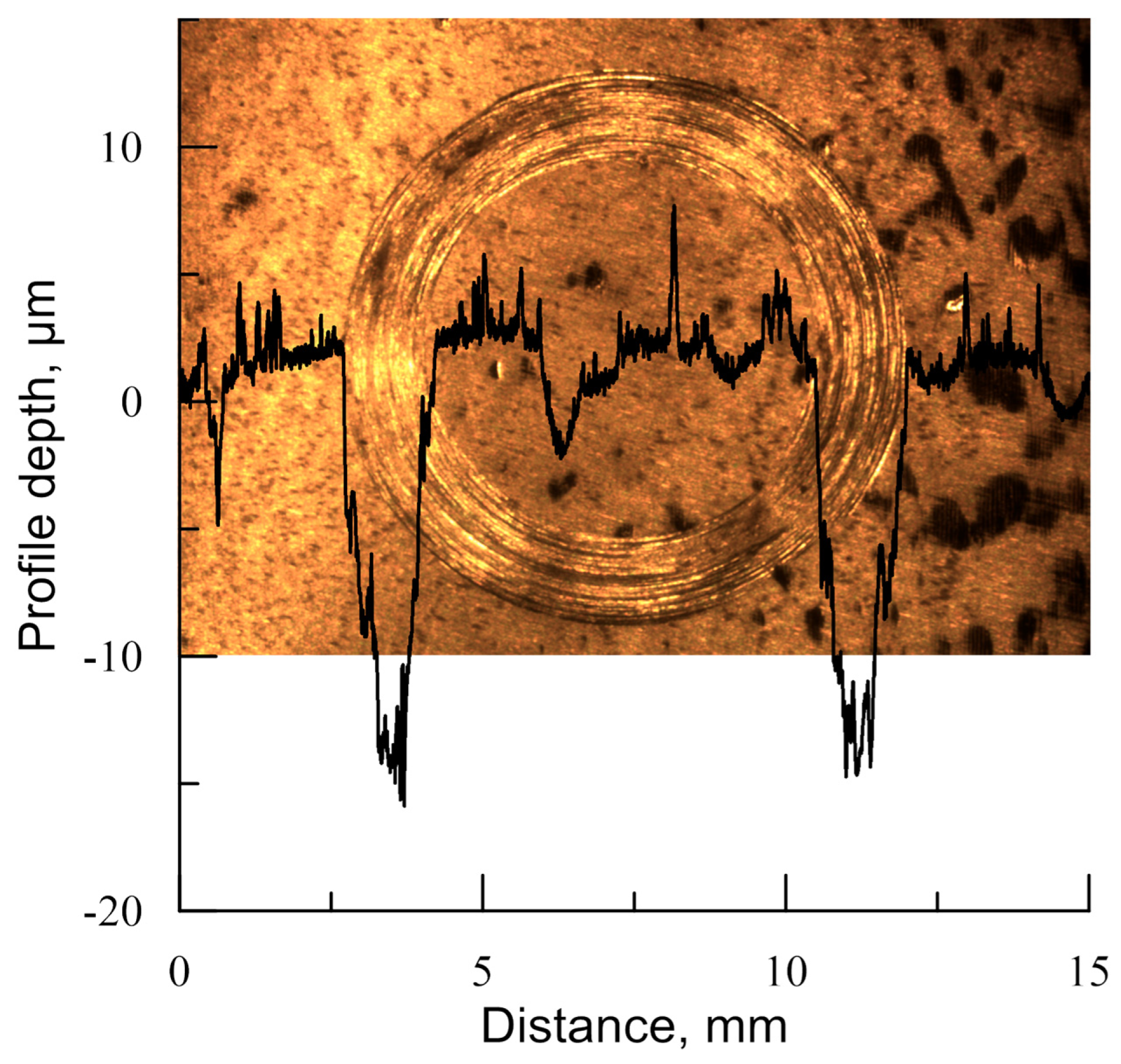
| Specimen No. | Max. Wear Track Depth, µm | The Coefficient of Friction | Surface Roughness, Ra, µm | Surface Roughness, Rz, µm |
|---|---|---|---|---|
| 1 | 33 | 0.5 | 0.684 | 4.351 |
| 3 | 28 | 0.7 | 0.272 | 2.134 |
| 4 | 19 | 0.52 | 0.533 | 2.950 |
| 5 | 17 | 0.5 | 0.310 | 4.237 |
Disclaimer/Publisher’s Note: The statements, opinions and data contained in all publications are solely those of the individual author(s) and contributor(s) and not of MDPI and/or the editor(s). MDPI and/or the editor(s) disclaim responsibility for any injury to people or property resulting from any ideas, methods, instructions or products referred to in the content. |
© 2024 by the authors. Licensee MDPI, Basel, Switzerland. This article is an open access article distributed under the terms and conditions of the Creative Commons Attribution (CC BY) license (https://creativecommons.org/licenses/by/4.0/).
Share and Cite
Khmyrov, R.S.; Korotkov, A.; Gridnev, M.; Podrabinnik, P.; Tarasova, T.V.; Gusarov, A.V. Phase Composition, Microstructure and Mechanical Properties of Zr57Cu15Ni10Nb5 Alloy Obtained by Selective Laser Melting. J. Manuf. Mater. Process. 2024, 8, 10. https://doi.org/10.3390/jmmp8010010
Khmyrov RS, Korotkov A, Gridnev M, Podrabinnik P, Tarasova TV, Gusarov AV. Phase Composition, Microstructure and Mechanical Properties of Zr57Cu15Ni10Nb5 Alloy Obtained by Selective Laser Melting. Journal of Manufacturing and Materials Processing. 2024; 8(1):10. https://doi.org/10.3390/jmmp8010010
Chicago/Turabian StyleKhmyrov, Roman S., Andrey Korotkov, Mikhail Gridnev, Pavel Podrabinnik, Tatiana V. Tarasova, and Andrey V. Gusarov. 2024. "Phase Composition, Microstructure and Mechanical Properties of Zr57Cu15Ni10Nb5 Alloy Obtained by Selective Laser Melting" Journal of Manufacturing and Materials Processing 8, no. 1: 10. https://doi.org/10.3390/jmmp8010010
APA StyleKhmyrov, R. S., Korotkov, A., Gridnev, M., Podrabinnik, P., Tarasova, T. V., & Gusarov, A. V. (2024). Phase Composition, Microstructure and Mechanical Properties of Zr57Cu15Ni10Nb5 Alloy Obtained by Selective Laser Melting. Journal of Manufacturing and Materials Processing, 8(1), 10. https://doi.org/10.3390/jmmp8010010