Article

A Computational Method for the Nonlinear Attainable Moment Set of Tailless UAVs in Flight-Control-Oriented Scenarios

National Key Laboratory of Unmanned Aerial Vehicle Technology, Equipment Management and Unmanned Aerial Vehicle Engineering College, Airforce Engineering University, Xi’an 710072, China
*
Authors to whom correspondence should be addressed.
Drones 2025, 9(8), 585; https://doi.org/10.3390/drones9080585
Submission received: 11 July 2025 / Revised: 11 August 2025 / Accepted: 15 August 2025 / Published: 18 August 2025

Abstract

Tailless unmanned aerial vehicles (UAVs) achieve high-agility maneuvers with flight control systems. The attainable moment set (AMS) provides critical theoretical foundations and constraints for their optimization. A computational method is proposed herein to address controllability limitations caused by nonlinear aerodynamic effectiveness. This method incorporates dual constraints on control surface angles and angular rates for the nonlinear AMS, aiming to meet the demands of attitude tracking dynamics in flight control systems. First, a quantitative model is established to correlate dual deflection constraints with aerodynamic moment amplitude and bandwidth limitations. Next, we construct a computational framework for the incremental attainable moment set (IAMS) based on differential inclusion theory. For monotonic nonlinear aerodynamic effectiveness, the vertices of the IAMS are updated using local interpolation, yielding the incremental nonlinear attainable moment set (INAMS). When non-monotonic nonlinearity occurs, stationary points are calculated to adjust the control effectiveness matrix and admissible control set, thereby reducing computational errors induced by non-monotonic characteristics. Furthermore, the effective actions set, derived from a time-varying incremental nonlinear attainable moment set, quantifies the residual moment envelope of tailless UAVs during maneuvers. Comparative simulations indicate that the proposed method achieves correct computation under nonlinear aerodynamic conditions while reliably determining safe flight boundaries during control failure.

1. Introduction

In recent years, high maneuverability and stealth capability have remained critical technological priorities for advanced aircraft. Representative developments include not only operational fifth-generation aircraft, but also the next-generation air dominance program, which defines the design paradigm for sixth-generation aircraft. All conceptual platforms under the next-generation air dominance program feature tailless overactuated flying-wing configurations. For the tailless UAVs, high-agility maneuvers, such as snake-shaped maneuvers [1], can fully utilize the advantages of maneuverability and improve survivability, but they also pose challenges to the flight control system [2]. Therefore, an algorithm for identifying the residual available aerodynamic moments of the aircraft needs to be developed to assist in the scientific design of the tracking controller. However, when the number of control surfaces exceeds that of pseudo-control commands, deflection commands generated by different allocation algorithms exhibit non-uniqueness. Moreover, advanced aircraft often integrate complex actuator architectures, leading to strongly nonlinear characteristics in the aerodynamic effectiveness with respect to deflection angles or state variables. Concurrently, the coupling of control surfaces exerts a substantial influence on control performance and cannot be disregarded. These factors collectively render the nonlinear AMS of tailless UAVs challenging to derive [3,4], thereby impeding precise agile control strategies that fully exploit their maneuverability potential. The AMS not only serves as a metric for evaluating the aerodynamic performance of aircraft configurations and control surface structures, but also quantifies residual moments during flight control operations. These two functions establish a scientific foundation for flight control systems.
Constrained by the physical limitations of aircraft actuators, the AMS represents a bounded attainable set describing the feasible control domain of aircraft [5]. These physical limitations, including deflection angle and angular rate constraints of control surfaces, are collectively referred to as the admissible controls set [6]. Since the AMS was first proposed by Durdam, it has been widely adopted in diverse fields, including tracking control [7,8,9,10,11], control allocation [6,12,13,14,15,16,17,18], and aircraft configuration design [19,20]. In tracking control applications, the AMS is primarily used to compute safety boundaries, assist fault-tolerant control, and evaluate system controllability. In control allocation applications, it is employed to compare the performance of different allocation algorithms or to directly participate in innovative allocation algorithm design. For aircraft configuration design, the AMS serves to evaluate the aerodynamic performance of different configurations.
Despite the aforementioned advantages, as advanced overactuated tailless aircraft become increasingly complex, targeted improvements and innovations to classical AMS algorithms are required. Varriale and Voskuijl [16] introduced virtual control surfaces that provide bijective mapping to aerodynamic moments to fulfill the computational demands of the AMS in pilot-in-the-loop systems. These virtual surfaces enable linear mapping relationships with pilot control sticks. By replacing the control effectiveness matrix with a mapping matrix between physical control surfaces and virtual surfaces, classical AMS algorithms are utilized to compute the attainable actions set. An attainable actions set is essentially a subset of the AMS. A key limitation of this approach lies in its dependency on the selected control allocation algorithm, as different algorithms yield distinct results. Yu et al. [10] investigated trajectory tracking control for four-wheel-drive ground vehicles. Their approach integrated nonlinear friction effects into the virtual surface mapping matrix, deriving the required attainable force set for tracking controllers based on classical AMS frameworks. Both studies share a common strategy: extending classical AMS algorithms to broader applications through virtual surface concepts. This strategy also represents a predominant characteristic of current AMS innovation research. Zhang et al. [21] investigated controllability challenges in electric vertical take-off and landing vehicles with actuator failures. Their methodology optimizes intersections between the classical AMS and operational envelopes, significantly improving fault-tolerant performance. In summary, most recent AMS innovations remain anchored to classical linear formulations without fundamentally overcoming their inherent limitations. Therefore, the reliable and efficient computation of the nonlinear AMS warrants in-depth investigation.
A classical approach in nonlinear aerodynamic effectiveness research is the nonlinear AMS computation method proposed by Bolender et al. [12]. With this method, the control effectiveness matrix is first computed using the least squares approach. Based on the above, Bolender identified aerodynamic moment boundaries within the feasible deflection range of control surfaces using optimization functions. This algorithm exhibits three primary limitations: (1) it assumes no coupling between control surfaces; (2) it models nonlinear aerodynamic effectiveness solely through quadratic functions; and (3) its optimization process incurs excessive computational loads. These limitations persist as fundamental challenges in subsequent NAMS studies. Jonasson et al. [22] proposed a brute-force method for attainable set computation in overactuated systems, which exhaustively evaluated all possible actuator combinations. According to the authors, this brute-force method remains viable only for low-dimensional actuator configurations and is inadequate for advanced high-dimensional aircraft. Söpper et al. [9] computed the required attainable set to investigate aircraft controllability under disturbances. By modeling aerodynamic moments with quadratic functions, they derived the minimum required attainable set for flight control. However, the key constraint of Söpper arises from its dependence on the convexity of the AMS. This requirement is not universally valid for tailless UAVs.
Despite the above advancements in linear and nonlinear AMSs, the following challenges persist:
  • Incomplete integration of the constraints from the admissible control set. During the design of the flight control system, the AMS must be tightly coupled with control algorithms. Therefore, AMS innovations should consider the constraints from the admissible control set, including but not limited to deflection angle and angular rate limitations.
  • Inadequate consideration of nonlinear characteristics. Aerodynamic moments and deflection angles of control surfaces typically exhibit nonlinear relationships. Algorithms based on classical AMS frameworks fail to produce accurate results due to linear assumptions.
  • Insufficient handling of multivariable coupling. Moment computation for control surfaces involves multiple coupled variables and parameters, such as deflection angles, angle of attack, flight velocity, and altitude. The intricate interdependencies among these variables necessitate comprehensive multifactor integration in AMS calculations.
In contrast with the above innovations, Pfeifle and Fichter [17,18] introduced an attainable subset analysis method based on incremental deflections during the development of an incremental control allocation algorithm. Based on differential inclusion theory, the subset formed by incremental deflections is guaranteed to reside within the AMS. Pfeifle further investigated the constraints imposed by these incremental subsets on control allocation at the boundary of the AMS. While the AMS primarily served as an analytical tool in Pfeifle’s work, such a computational framework for incremental deflections provides critical insights for nonlinear AMS research. Building on this premise, we develop a computational method for the nonlinear AMS of tailless UAVs in flight-control-oriented scenarios with three key contributions:
  • Mapping the constraints from the admissible control set for enhanced AMS reliability. We map the constraints from the admissible control set, including deflection angle and angular rate limits, to aerodynamic moment amplitude and bandwidth boundaries. This mapping process enhances the reliability and accuracy of the AMS.
  • Nonlinear AMS computation with a nonlinear aerodynamic model. We develop a dedicated NAMS algorithm to address nonlinear aerodynamic effectiveness and control surface coupling. The non-monotonic characteristics in the aerodynamic effectiveness function are addressed by fitting functions and calculating stationary points.
  • Dynamic nonlinear AMS computation and validation. The algorithm dynamically computes the nonlinear AMS by integrating real-time control parameters. We conduct flight control simulations to validate feasibility and effectiveness. These simulations utilize the admissible control set derived from the nonlinear AMS to quantify residual moments of tailless UAVs.
Aligned with the design objectives, this paper is structured as follows: In Section 2, we analyze the computational challenges of the nonlinear AMS by synthesizing the aerodynamic characteristics of tailless UAVs and the requirements of the flight control system. Section 3 comprises two parts: In Section 3.1, we propose an IAMS computational method under the constraints of an admissible control set. In Section 3.2, we extend the IAMS framework to address nonlinear aerodynamic effectiveness, developing a methodology for the nonlinear AMS. This algorithm further generates an effective actions set for flight control applications. In Section 4, we validate the innovations in Section 3 through comparative simulations on overactuated tailless aircraft.

2. Problem Formulation and Preliminaries

To ensure the scalability and verifiability of the nonlinear AMS, we adopt the Innovative Control Effector (ICE) aircraft as a platform for theoretical analysis and simulation. As shown in Figure 1, the ICE aircraft serves as a canonically overactuated testbed, featuring aerodynamic configurations aligned with the next-generation air dominance program. In more detail, the ICE aircraft is a land-based tailless delta-wing platform with a 65 deg leading-edge sweep angle, equipped with six groups of 11 independent effectors, which contain an all-moving wing tip (AMT), a spoiler slot deflector (SSD), elevon (ELE), a pitch flap (PF), and a leading-edge flap (LEF). The LEF is subdivided into the inboard LEF (ILEF) and the outboard LEF (OLEF) [21]. All effectors are symmetrically distributed along the longitudinal axis of the aircraft. Excluding the PF, which operates in bilateral symmetric mode, all other surfaces provide independent differential deflection capabilities, collectively enabling 11 distinct control degrees of freedom.
In ICE aircraft, the relationship between effectors (serving as control inputs) and the aerodynamic moments L , M , N can be formulated as follows:
L = C L q ¯ S ref b ref M = C M c ¯ + C Z x ac x cg q ¯ S ref N = C N b ref C Y x ac x cg q ¯ S ref
where C L , C M , C N denote the roll, pitch, and yaw moment coefficients; C Y , C Z denote the aerodynamic force coefficients along the body-fixed axes; q ¯ denotes the aerodynamic pressure; S ref denotes the reference area of the fuselage and wing span; b ref and c ¯ correspond to the length of the wingspan and mean aerodynamic chord, respectively; and x ac and x gc are the aerodynamic center and center of gravity of the tailless UAV. Based on Equation (1), the effective actions set refers to the time-varying residual moments constrained by the aircraft configuration and admissible control set during flight control. Put simply, tailless UAVs cannot generate aerodynamic moments beyond the effective actions set. The effectors’ command δ is mapped to L , M , N by C L , C M , C N , C Y , C Z :
C L = f L α , β , p , r , υ , h , δ C M = f M α , β , q , υ , h , δ C N = f N α , β , p , r , υ , h , δ C Y = f Y α , β , υ , h , δ C Z = f Z α , β , υ , h , δ
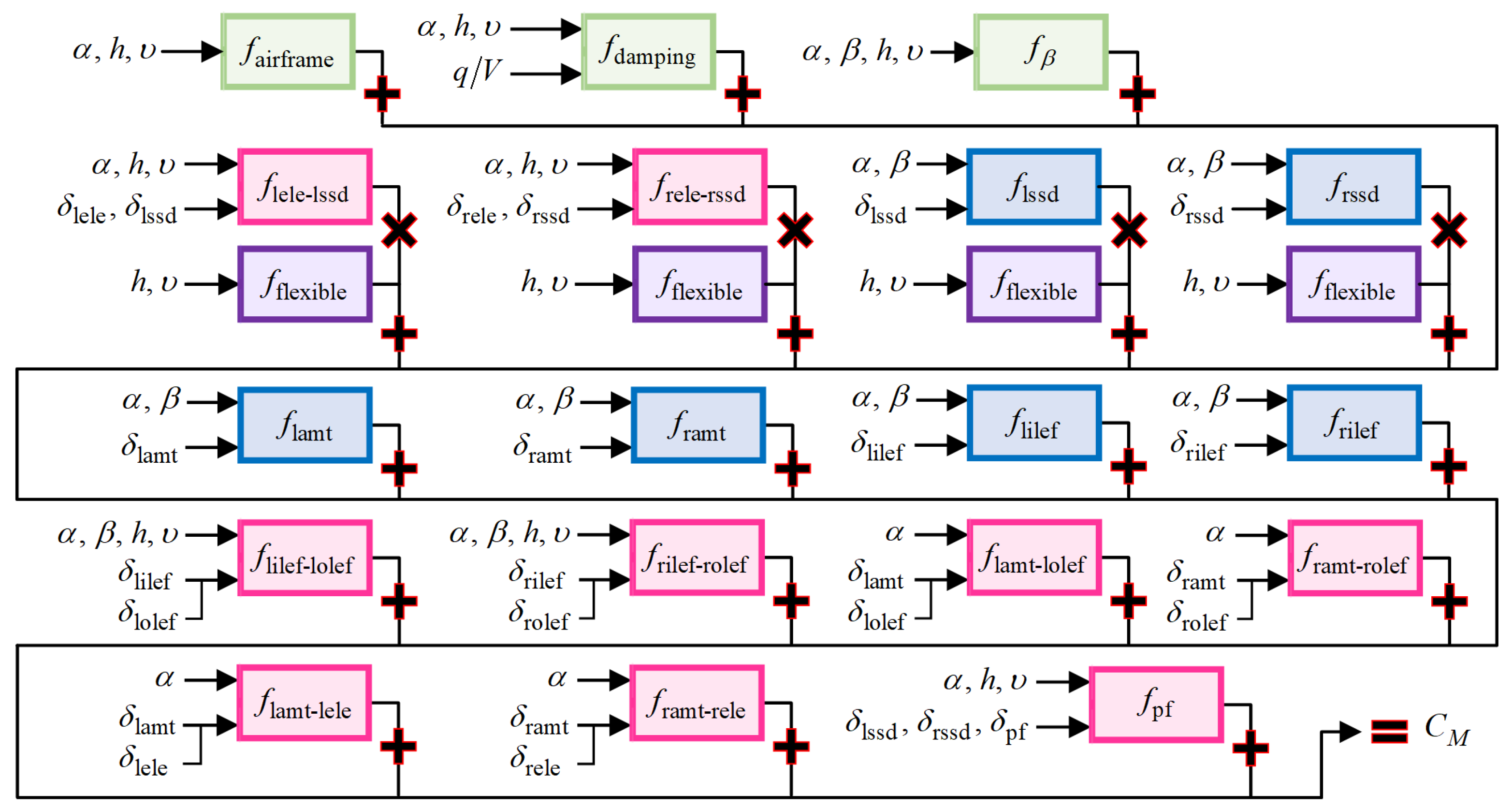
where α , β denote the angle of attack and sideslip angle between the airflow coordinate system and the body coordinate system. p , q , r denote the roll, pitch, and yaw rates in the body coordinate system. υ denotes the aircraft velocity. h denotes the flight altitude. δ = δ lilef , δ lolef , δ lamt , δ lele , δ lssd , δ pf , δ rilef , δ rolef , δ ramt , δ rele , δ rssd T denotes the effectors’ deflection. Taking AMT as an example, δ lamt denotes the deflection angle of the left AMT, and δ ramt corresponds to the right. δ pf is an exception, denoting the deflection angle of both the left and right PF. Detailed derivations of the parameters are provided in [23] and, thus, omitted herein. The mapping relationships described in Equations (1) and (2) are applicable to most overactuated aircraft. To investigate the mechanisms of dynamic coupling between δ and flight state variables, the pitch moment coefficient C M is selected as an example. Figure 2 illustrates the nonlinear generation path model from δ to C M .
This model quantifies the nonlinear superposition processes involving aerodynamic effectiveness, inertial coupling, and aeroservoelastic effectiveness during moment generation. Based on the path model described in Figure 2, the number of effectors n = 11 , C M = f M can be formulated as follows:
C M = f airframe α , h , υ + q / υ f damping α , h , υ + f β α , β , h , υ f flexible h , υ i n f i α , β , h , υ , δ i + i j n f i j α , β , h , υ , δ i , δ j ,
where f airframe denotes the aerodynamic effectiveness that arises from the airframe, f damping denotes the aerodynamic effectiveness that arises from the aerodynamic damping, and f flexible denotes the aerodynamic effectiveness that arises from the elastic deformation of the wings. The effectors’ coupling originates from f i j , while the nonlinear aerodynamic effectiveness arises from f i and f i j . The compositions of other aerodynamic forces and moments follow similar principles to those illustrated in Figure 2 and Equation (3). Through the analytical decomposition of C M , we find three critical characteristics among δ , state variables, and C M : (1) different limitations from the admissible control set directly influence the computation of aerodynamic moment coefficients, thereby determining the accuracy of L , M , N ; (2) the nonlinear characteristics of the nonlinear AMS stem from the superposition of nonlinear aerodynamic effectiveness induced by both aircraft configuration and effectors’ dynamics; and (3) flight state variables significantly affect the computation of the nonlinear AMS in the flight control system.
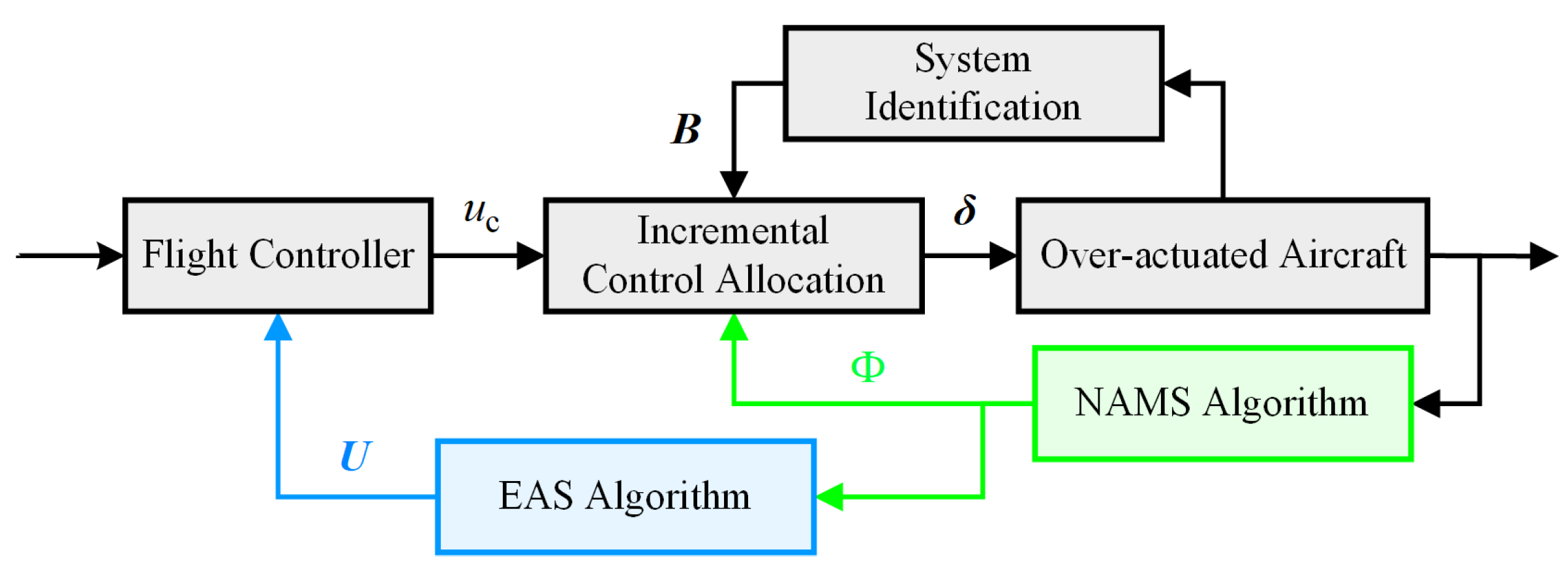
From the above, it is, therefore, necessary to further analyze the logical relationship between the nonlinear AMS and flight control systems, which is introduced in Figure 3. For a tailless UAV, the flight control system typically includes two parts: a trajectory-tracking controller and a control allocation algorithm. The flight controller calculates the desired moment vector u c = L c , M c , N c T R 3 , while the output of the flight control system is δ ( t ) R n . Thus, control allocation solves for B δ ( t ) = u c ( t ) to obtain δ ( t ) under given u c ( t ) and the control effectiveness matrix B : R n R 3 . Thereafter, δ ( t ) will generate the actual aerodynamic moment u = L , M , N T , thereby achieving effective attitude control. During this control process, the nonlinear AMS synchronously computes the complete attainable moment set Φ based on δ ( t ) and state variables. The effective actions set will be derived from Φ . Φ and effective actions set essentially predict the nonlinear AMS algorithm’s residual maneuver margin at the current time step. The prediction is derived from the control system’s information at the previous time step.
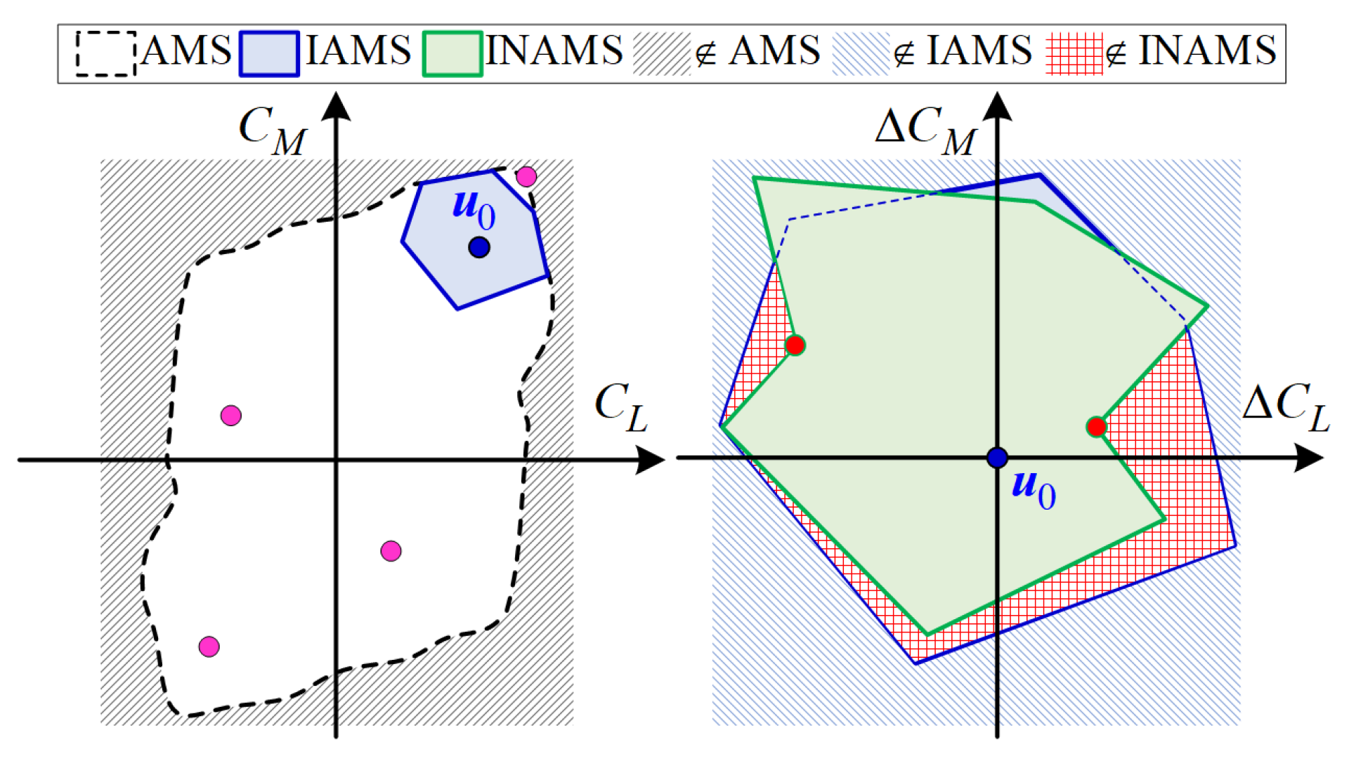
Based on the preceding analysis, the specific issues to be considered in the nonlinear AMS algorithm can be illustrated under the mapping condition shown in Figure 4. The black dashed region “AMS” represents the AMS constrained by effectors’ angles, the blue solid region “IAMS” represents the IAMS under the constraints of the admissible control set, and the green dashed region “INAMS” represents the nonlinear AMS incorporating non-monotonic characteristics. For the control system, the pink point represents the aerodynamic moment within the tailless UAVs’ AMS that cannot be achieved under the current system state u 0 . Therefore, only any point within the IAMS constitutes the truly attainable set for the control system. However, control effectiveness nonlinearity, particularly non-monotonic behaviors, results in computational inaccuracy in the IAMS. The red shaded area ‘ INAMS ’ represents the erroneous attainable set caused by such computational inaccuracy. The red points represent new vertices caused by non-monotonic effectiveness.
The implementation of the nonlinear AMS algorithm primarily involves two steps. Firstly, the mapping relationship between deflection angle/angular rate and the amplitude bandwidth of u c is established using the IAMS that is constrained by an admissible control set. Secondly, control effectiveness nonlinearity in nonlinear AMS computation is resolved by leveraging the IAMS framework with local adaptive interpolation and the stationary point method. This methodology ultimately yields a nonlinear AMS applicable to a flight control system.

3. Computational Method for the Nonlinear Attainable Moment Set

3.1. Flight-Control-System-Dynamics-Integrated AMS Computation Under the Constraints of the Admissible Control Set

In contrast with [19,20], the authors of which compute the AMS based on effectors’ angle only, the flight control system demands a state-dependent AMS derived from previous time step conditions [6,12,13,14,15,16,17,18]. Consequently, the AMS calculation must strictly integrate both deflection rate and actuation range constraints, as mathematically expressed by Equation (4):
δ ( t ) = δ 1 , δ 2 , , δ n δ i δ _ i , δ ¯ i
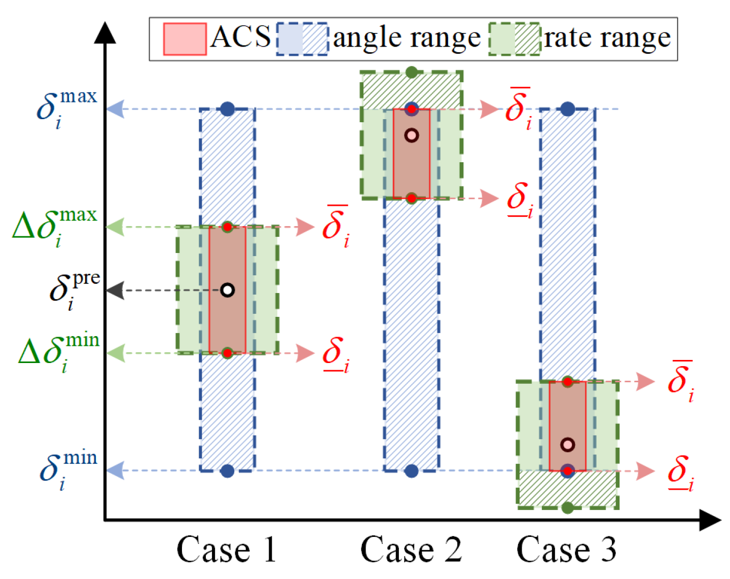
where δ _ i = max δ i min , Δ δ i min + δ i pre , δ ¯ i = min δ i max , Δ δ i max + δ i pre , i = 1 , 2 , , n . The superscripts “ * max ” and “ * min ” denote the maximum and minimum values of a variable. The superscript “ * pre ” denotes the value from the previous time step in the flight control system. It is critical to emphasize that, for a flight control system, converting deflection rate constraints into deflection increment constraints by Δ δ = t 0 t 0 + Δ t δ ˙ ( τ ) d τ is more physically meaningful, where Δ t is the sampling interval of the control system. In Equation (4), δ _ i , δ ¯ i defines the admissible control set of the tailless UAV considered in this study. Consequently, the relationship between the Δ δ and u c is derived as follows.
B δ = B Δ δ + δ pre = u c
The relationships among Δ δ , δ pre in Equation (5) and δ _ i , δ ¯ i in Equation (4) can be geometrically interpreted using the schematic diagram shown in Figure 5.
For B, two computation methods are typically employed. The first approach involves applying a finite difference approximation at a specified actuator deflection position to compute the local slope as the gain coefficient. The second method involves calculating the least squares fit over the entire actuation range, where the fitted parameters represent the gain coefficients [12]. Considering the constraints on the deflection rate and the need for effectors’ coupling, we adopt the first approach. Using the central difference theorem, the element in the m-th row and i-th column of B is computed as follows:
B m , i = C m α , β , υ , h , δ δ i = C m α , β , υ , h , δ 0 , δ i + C m α , β , υ , h , δ 0 , δ i δ i + δ i
where m = 1 , 2 , 3 corresponds to the aerodynamic coefficients of L , M , N . δ 0 denotes the vector of effectors’ deflection at the trimmed state. δ = δ 0 while the i-th of δ is replaced by δ i + or δ i . δ i + = δ 0 ( i ) + δ ¯ i δ _ i / 2 , δ i = δ 0 ( i ) δ ¯ i δ _ i / 2 . δ i + δ i represents the sampling length for B m , i . For a tailless UAV, the physical interpretation of Equation (6) is as follows: under the current flight condition, the control gain coefficient B m , i quantifies the contribution of the i-th effectors to the m-th aerodynamic moment when the i-th effectors is deflected while all others remain fixed. A detailed explanation can be found in [24], which will not be repeated herein.
It is critical to emphasize that B identified by Equation (6) not only effectively addresses the effectiveness of effectors’ coupling, but also dynamically adapts to the state variables of the flight control system. Therefore, Equation (6) can also be expressed as B m , i = f m , i α , β , υ , h , δ i . Since u c pre B δ pre , Equation (4) should be reformulated as follows.
B Δ δ + u c pre = u c
From the above, the problem of solving the AMS under deflection rate constraints can, therefore, be reformulated as computing the IAMS, defined as B Δ δ . Based on differential inclusion theory, the IAMS is a subset of the AMS. Let b i = b L i , b M i , b N i T denote the control gain vector of δ i for L , M , N . The control effectiveness matrix is then constructed as B = b 1 , b 2 , , b n . The control subspace Ω , under the mapping B : R n R 3 , generates the IAMS Φ 1 . For any five effectors δ a 1 , δ a 2 , δ a 3 , δ a 4 , δ a 5 in δ , Equation (7) can be derived as Δ u = B Δ δ and it can be further expanded as follows:
Δ u = b L , a 1 b L , a 2 b L , a 3 b M , a 1 b M , a 2 b M , a 3 b N , a 1 b N , a 2 b N , a 3 · Δ δ a 1 Δ δ a 2 Δ δ a 3 + b L , a 4 b M , a 4 b N , a 4 Δ δ a 4 + b L , a 5 b M , a 5 b N , a 5 Δ δ a 5 + j = 1 n b L , j b M , j b N , j Δ δ j
where j a 1 , a 2 , a 3 , a 4 , a 5 . For computational convenience, Equation (8) can be reformulated as follows.
Δ u = Δ u 1 + Δ u 2
Δ u 1 = b L , a 1 b L , a 2 b L , a 3 b M , a 1 b M , a 2 b M , a 3 b N , a 1 b N , a 2 b N , a 3 · Δ δ a 1 Δ δ a 2 Δ δ a 3
Δ u = b L , a 1 b L , a 2 b L , a 3 b M , a 1 b M , a 2 b M , a 3 b N , a 1 b N , a 2 b N , a 3 · Δ δ a 1 Δ δ a 2 Δ δ a 3 + b L , a 4 b M , a 4 b N , a 4 Δ δ a 4 + b L , a 5 b M , a 5 b N , a 5 Δ δ a 5 + j = 1 n b L , j b M , j b N , j Δ δ j
To ensure the feasibility of the IAMS, the following assumptions are imposed:
Assumption 1.
Any 3 × 3 submatrix within the control effectiveness matrix B is full rank.
Assumption 2.
B m , i = f m , i α , β , υ , h , δ i  is monotonic within the admissible control set.
Assumption 1 guarantees the convexity of the IAMS defined by Equation (9) from the perspective of flight control dynamic response. Assumption 2, combined with the findings in [3], serves as a sufficient condition for n 2 control variables to reside at their boundary values δ _ i δ i pre , δ ¯ i δ i pre when representing points on the surface of Φ 1 by Equation (8). If Assumptions 1 and 2 hold simultaneously, the parallelism invariance of hyperplanes under linear mapping yields the following result.
The surface Ω of the n-dimensional hypercube Ω , when mapped through B : R n R 3 , contains C n 2 groups of planes. Each group consists of 2 n 2 mutually parallel parallelograms. Each two planes with the maximum orthogonal distance within each group constitute the surface Φ 1 of Φ 1 . Thus, Φ 1 is composed of 2 C n 2 parallelograms. Therefore, the boundary Φ 1 can be determined by identifying the two farthest planes within each group.
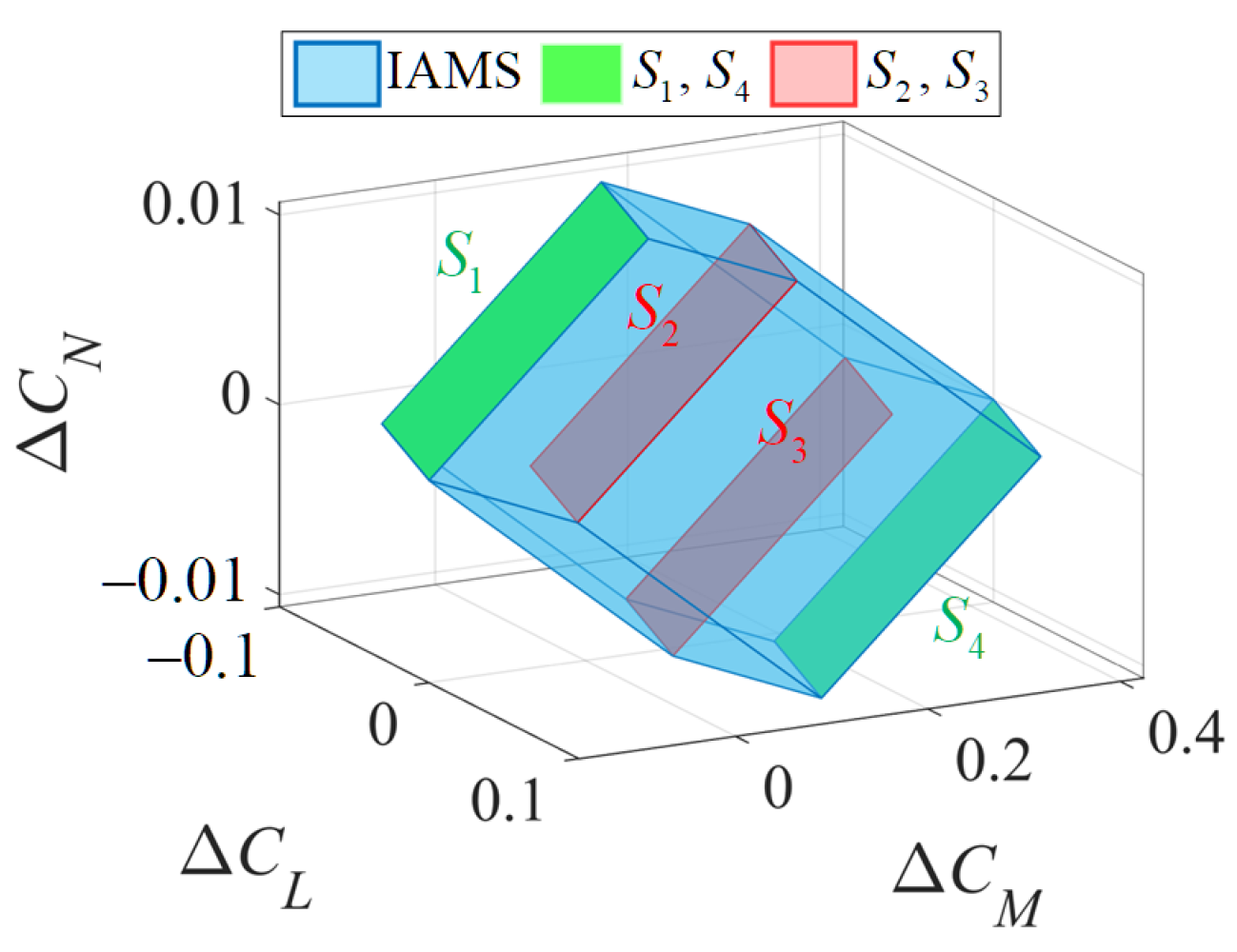
To illustrate the selection process of Φ 1 , consider the mapping B : R 4 R 3 . In this case, Φ 1 contains C 4 2 = 6 groups of parallel planes, with each group comprising 2 2 parallel planes. The corresponding IAMS can be represented as shown in Figure 6.
As shown in Figure 6, S 1 , S 2 , S 3 , S 4 represent four parallel planes within one group of C 4 2 combinations. The outermost planes S 1 , S 4 are selected to form Φ 1 . Based on this logic, the computational procedure for the IAMS is defined as follows: let ξ i , j i j = 1 , 2 , , n denote a group of parallel planes determined by allowing Δ δ i and Δ δ j in Δ δ to vary freely within the admissible control set, while keeping all other elements constant:
ξ i , j = Δ u Δ u = b L i b M i b N i b L j b M j b N j T · Δ δ i Δ δ j + k = 1 n b L k b M k b N k T Δ δ k
where k i , j . The coordinate system is rotated by Δ u = T B Δ δ = B Δ δ such that the transformed coordinate axis Δ C L is orthogonal to ξ i , j . Based on the orthogonality of vectors, B satisfies the following.
B 1 , i = 0 B 1 , j = 0
By setting the rotation matrix T = t 11 , t 12 , t 13 ; t 21 , t 22 , t 23 ; t 31 , t 32 , t 33 and substituting T B = B into Equation (13), we obtain the following.
t 11 t 12 = b L i b M i b L j b M j 1 · b N i b N j t 13
After rotation, ξ i , j intersects and remains orthogonal to the Δ C L axis. Let the intersection be Δ u = L , 0 , 0 T . Substituting Equation (14) into Equation (12), L can be derived as follows:
L = t 13 Δ t b L i b M j b L j b M i k = 1 n η T · b L k b M k b N k T Δ δ k
where η = b i × b j is the normal vector of ξ i , j . It is critical to clarify that the intersection of the rotated plane ξ i , j with the Δ C L axis does not equate to determining the extremum values along the Δ C L axis. Consequently, rotating the coordinate system to align with the Δ C L , Δ C M , or Δ C N by Equation (14) yields identical results in terms of the relative distance values between parallel planes in spatial coordinates.
For the outermost surfaces of Φ 1 along the direction Δ u , they are the planes ξ i , j corresponding to extremal values of L (maximum or minimum) under the control inputs Δ δ k . Therefore, the values of the remaining n 2 control variables can be determined based on the sign relationship between η T · b k and L . The vertices u top on the upper boundary surface of Φ 1 are defined as follows:
u 1 top = k = 1 n Δ u k max + b i δ _ i δ i pre + b j δ _ j δ j pre u 2 top = k = 1 n Δ u k max + b i δ _ i δ i pre + b j δ ¯ j δ j pre u 3 top = k = 1 n Δ u k max + b i δ ¯ i δ i pre + b j δ _ j δ j pre u 4 top = k = 1 n Δ u k max + b i δ ¯ i δ i pre + b j δ ¯ j δ j pre
where
Δ u k max = b k δ ¯ k δ k pre i f b k T η > 0 b k δ _ k δ k pre i f b k T η < 0
where k i , j . u bot on the lower boundary surface of Φ 1 is defined as follows:
u 1 bot = k = 1 n Δ u k min + b i δ _ i δ i pre + b j δ _ j δ j pre u 2 bot = k = 1 n Δ u k min + b i δ _ i δ i pre + b j δ ¯ j δ j pre u 3 bot = k = 1 n Δ u k min + b i δ ¯ i δ i pre + b j δ _ j δ j pre u 4 bot = k = 1 n Δ u k min + b i δ ¯ i δ i pre + b j δ ¯ j δ j pre
where
Δ u k min = b k δ ¯ k δ k pre i f b k T η < 0 b k δ _ k δ k pre i f b k T η > 0
The vertex set computed by Equations (16)–(19) constitutes all vertices of Φ 1 . The IAMS algorithm serves two critical purposes in this study. Firstly, mapping the n-dimensional control bounds δ _ , δ ¯ to moment bounds u bot , u top in the flight control system. Secondly, providing actuator deflection references for subsequent nonlinear computations.

3.2. Incremental Nonlinear Attainable Moment Set (INAMS)

For advanced tailless UAVs, f k , i α , β , υ , h , δ i exhibits not only nonlinearity, but also non-monotonic characteristics. As shown in Figure 7, the above violates Assumption 2. Under nonlinear aerodynamic effectiveness, calculating IAMS by Section 3.1 will inevitably fail to accurately identify the residual moment of tailless UAVs. Therefore, this section focuses on designing the INAMS algorithm to compensate for computational errors caused by nonlinear aerodynamic effectiveness. Specifically, the IAMS primarily targets scenarios with linear f k , i . Under Assumptions 1 and 2, Φ 1 is composed of parallelograms. However, when f k , i exhibits nonlinear characteristics, Φ will consist of curved surfaces. Since Φ is inherently formed by interconnected surfaces, the key step lies in calculating the vertices that define the relative positions of these surfaces. For clarity, we replace the curved surfaces with planes constructed from the same vertices during research on the INAMS. This approach will improve computational accuracy while reducing computational load.
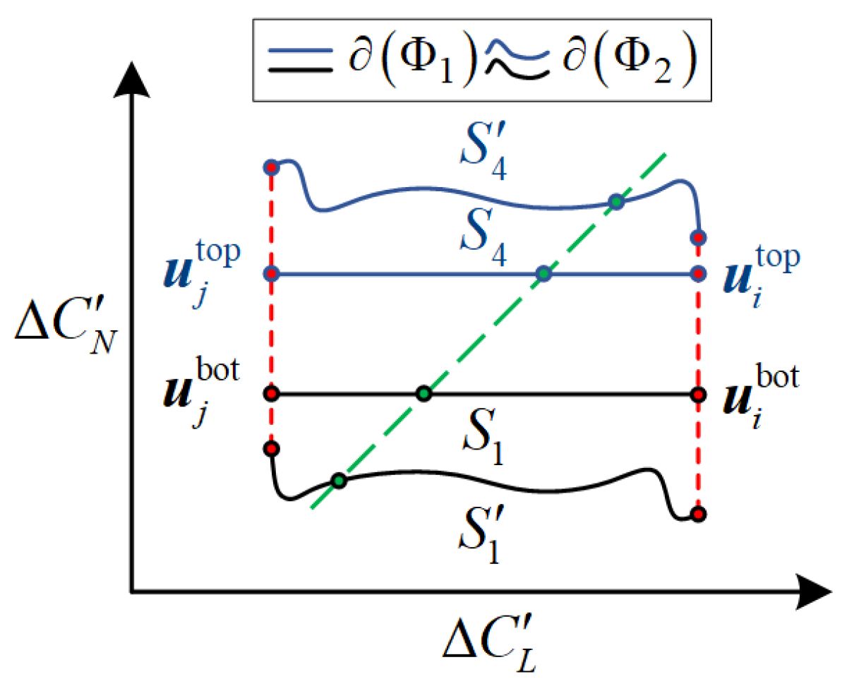
Consequently, the INAMS must tackle two challenges compared to the IAMS: (1) for monotonic nonlinear scenarios, approximation errors introduced by Equation (6) are resolved and (2) for non-monotonic nonlinear scenarios, erroneous vertices in Equations (16)–(19) are updated through stationary point calculations. The nonlinearity in the effectors’ effectiveness depicted in Figure 7 induces computational errors in the IAMS. For clarity, consider the parallel planes S 1 and S 4 illustrated in Figure 4. Rotate the coordinate system so that the C L O C N plane is perpendicular to S 1 and S 4 . Under this configuration, Φ 1 and the actual boundary Φ 2 should exhibit the relative relationship illustrated in Figure 8.
The upper and lower curves in Figure 8 represent the accurate attainable set boundary Φ 2 . Based on the preceding analysis, for nonlinear tailless UAVs, Φ 1 fails to precisely characterize the maneuverability space. Firstly, we address computational errors induced by monotonic nonlinearity in effectors’ effectiveness. These errors primarily stem from the linearization approach b δ adopted in Equations (16)–(19). Let δ 1 top , δ 2 top , δ 3 top , δ 4 top denote the deflection increments corresponding to u 1 top , u 2 top , u 3 top , u 4 top by Equations (16) and (17). Similarly, δ 1 bot , δ 2 bot , δ 3 bot , δ 4 bot are calculated for the lower boundary. The vertices on the upper surface of Φ 2 are calculated as follows:
u m top = f L δ m top + δ pre , f M δ m top + δ pre , f N δ m top + δ pre u pre
where m = 1 , 2 , 3 , 4 , and f L , f M , f N denote the fitted functions for aerodynamic moments obtained through local interpolation of wind tunnel data. f L , f M , f N inherently account for effectors’ coupling effectiveness based on the path model in Figure 2. Similarly, the vertices of the lower surface are calculated as follows.
u m bot = f L δ m bot + δ pre , f M δ m bot + δ pre , f N δ m bot + δ pre u pre
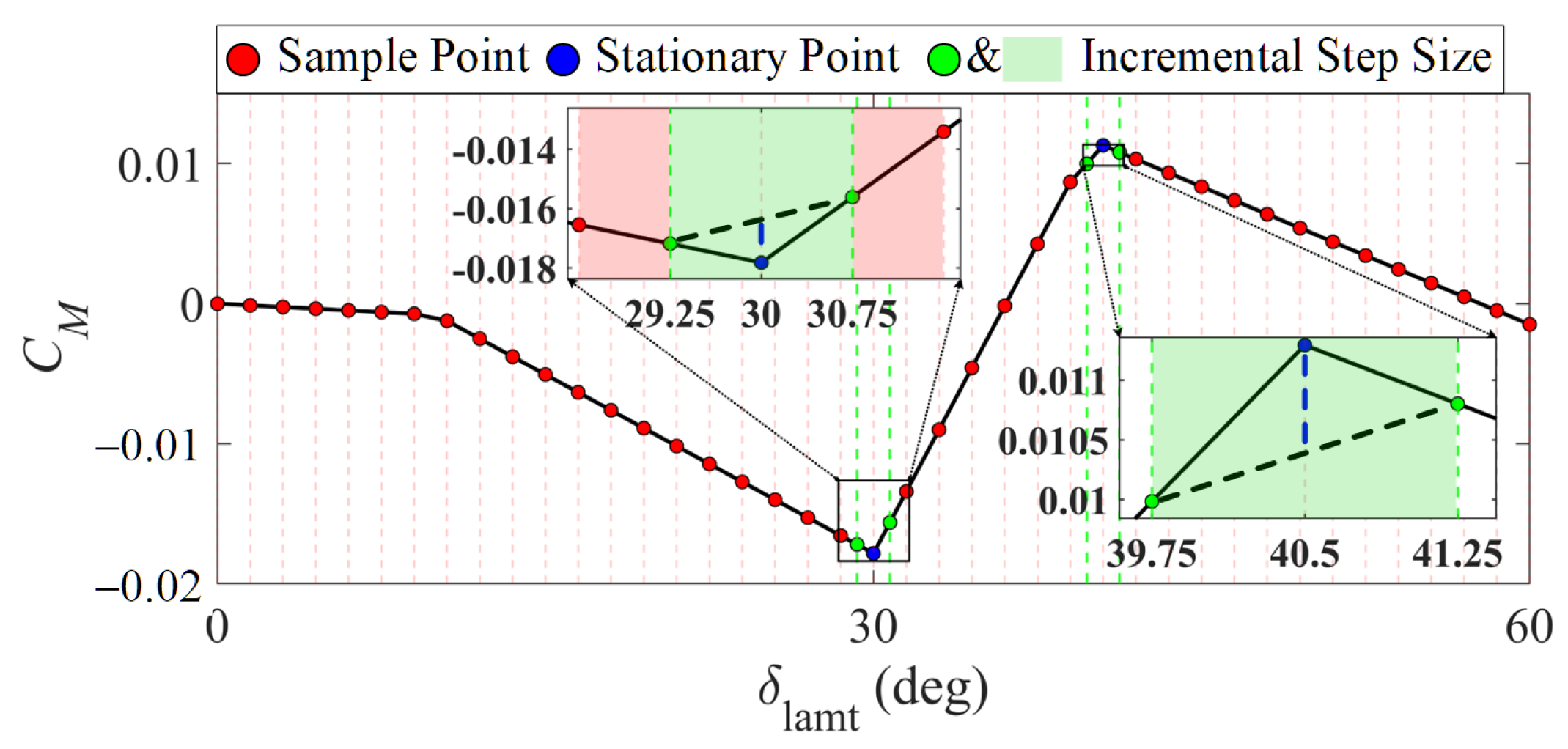
Secondly, we address computational errors in Φ 2 induced by non-monotonic nonlinearity. For monotonic effectors’ effectiveness, δ m top and δ m bot are evaluated at the boundaries of δ _ δ pre , δ ¯ δ pre . However, under non-monotonic nonlinearity, δ _ , δ ¯ will change. Consequently, Equations (20) and (21) still yield residual errors, as illustrated in Figure 9, which depicts the sectional schematic of Figure 7b at α = 85 deg .
In Figure 9, the red points and the red shaded area in the left enlarged view represent the sampling points of aerodynamic data, with a sampling step size of 1.5 deg. The blue points indicate two stationary points within the deflection angle range of left all moving wing tips. The green points and green shaded area denote the incremental step size of IAMS, with a step size of 1.5 deg. As shown in the left enlarged view in Figure 9, regardless of how the green incremental range shifts left or right, there is exactly one stationary point. This conclusion remains valid even if the adjacent point of the stationary point is also a stationary point. Therefore, for the IAMS, each δ _ k , δ ¯ k contains at most one stationary point, when the incremental calculation step size is not greater than the aerodynamic data sampling step size.
From the right enlarged view in Figure 9, the slope of the black dashed line represents B 2 , 3 calculated by Equation (6). The blue dashed line indicates computational errors caused by non-monotonic effectors’ effectiveness. For non-monotonic cases, the errors can be mitigated by calculating stationary points. As evident from Equations (20) and (21), non-monotonicity in effectors influences the accuracy of u m top and u m bot by δ m top and δ m bot . Consequently, the handling of non-monotonic scenarios involves two steps: (1) calibrating the deflection angles of n 2 effectors, excluding the i-th and j-th ones for each surface of Φ 2 , and (2) calibrating the deflection angles of both i-th and j-th effectors. From the above, the potential non-monotonicity in Equations (17) and (19) should, therefore, be addressed first, specifically:
δ k = δ k f T δ k = 0 , δ k δ _ k , δ ¯ k
where f T is the fitting function that characterizes the variation in L along Δ C L with respect to δ k over Φ 2 . In other words, f T characterizes the evolution of L , M , N along η as δ k changes. If the stationary point δ k exists, Equation (6) should be recalculated as follows.
B m , k = C m α , β , υ , h , δ 0 , δ k C m α , β , υ , h , δ 0 , δ _ k δ k δ _ k , i f δ k pre δ _ k , δ k B m , k = C m α , β , υ , h , δ 0 , δ ¯ k C m α , β , υ , h , δ 0 , δ k δ ¯ k δ k , i f δ k pre δ k , δ ¯ k
The above enables the subsequent computation of δ m top .
δ m top k = δ ¯ k δ k pre , i f b k T η > 0 & δ k pre δ k , δ ¯ k δ k δ k pre , i f b k T η > 0 & δ k pre δ _ k , δ k δ _ k δ k pre , i f b k T η < 0 & δ k pre δ _ k , δ k δ k δ k pre , i f b k T η < 0 & δ k pre δ k , δ ¯ k
Similarly, δ m bot can be computed with the same method. Building on the above, the non-monotonicity in boundary value selection for δ i and δ j (in Equations (16) and (18)) will be subsequently addressed. We assume that δ _ i , δ ¯ i or δ _ j , δ ¯ j contains at most one stationary point, respectively. Then, we obtain the following:
δ i j * = δ i , δ j 2 f F δ i δ j = 0
where δ i δ _ i , δ ¯ i , δ j δ _ j , δ ¯ j . Taking the upper surface of Φ 2 as an example, the effectors’ deflection configuration in the IAMS is as follows.
δ 1 top ( i ) = δ _ i δ i pre δ 1 top ( j ) = δ _ j δ j pre δ 2 top ( i ) = δ _ i δ i pre δ 2 top ( j ) = δ ¯ j δ j pre δ 3 top ( i ) = δ ¯ i δ i pre δ 3 top ( j ) = δ _ j δ j pre δ 4 top ( i ) = δ ¯ i δ i pre δ 4 top ( j ) = δ ¯ j δ j pre
In the updated Equation (26) of the INAMS, δ _ and δ ¯ are redefined as follows.
δ _ i = δ i j * 1 , i f δ i pre δ i j * 1 , δ ¯ i δ ¯ i = δ i j * 1 , i f δ i pre δ _ i , δ i j * 1 δ _ j = δ i j * 2 , i f δ j pre δ i j * 2 , δ ¯ j δ ¯ j = δ i j * 2 , i f δ j pre δ _ j , δ i j * 2
Substituting the updated δ m top and δ m bot into Equations (20) and (21) yield the vertices of Φ 2 . This concludes with the computational workflow of the INAMS. It is critical to note that the INAMS addresses nonlinear effectors’ coupling primarily through the vertices update. As illustrated in Figure 10, analogous to the wheel alignment of cars, Equations (17)–(27) perform vertex reposition for the IAMS. Moreover, the green surfaces constituting Φ 2 are derived from repositioning the vertices of the red surfaces in Φ 1 .
In general, the effective actions set describes the dynamic reachable boundary of aerodynamic moments along the three axes of the body-fixed Cartesian coordinate system. Distinct control allocation strategies induce divergent convergence paths for the allocated moments u toward u c on the INAMS boundary. Based on the above, the effective actions set is further designed to quantify residual moments, thereby providing a scientific foundation for tracking controller design. To ensure scalability, the computation of the effective actions set is designed to be independent of control allocation algorithms. In flight control systems, the effective actions set is defined as the dynamic reachable envelope of the aerodynamic moment vector within the body-fixed coordinate system. Therefore, in this study, the effective actions set is defined as the residual moment potential set of the INAMS along all three axes at the current control time step, mathematically represented as follows:
U = u ¯ E , u _ E u ¯ E = max u k top , u _ E = min u k bot
where k = 1 , 2 , 3 , 4 . For clarity, Figure 11 illustrates the effective actions set through orthographic projections along the three axes. Algorithm 1 provides the pseudocode for computing the INAMS and the effective actions set (EAS).
In summary, EAS serves not only as a quantitative analysis tool for the INAMS based on control system requirements, but also as a constraint set to ensure the feasibility of the flight control system in terms of physical realizability. Consequently, the effective actions set acts as the critical interface between the INAMS and the flight control system.
Algorithm 1 Incremental Nonlinear Attainable Moment Set
Drones 09 00585 i001

4. Experiment Evaluation and Comparison

The ICE aircraft described in Section 2, utilizing aerodynamic data from Lockheed Martin’s publicly available wind tunnel dataset, serves as the validation platform for comparative simulations. In this section, we present the results of analyses of the IAMS and INAMS based on the innovative designs presented in Section 3.1 and Section 3.2. Furthermore, snake-shaped and barrel roll maneuvers are implemented for comparative simulation. The snake-shaped maneuver is employed to validate the effectiveness of the innovative algorithms under high-agility conditions; in comparison, the barrel roll maneuver tests their reliability during control failure. In addition, the parameters of the ICE aircraft are set as shown in Table 1. In Table 2, the limits of effectors are introduced based on those outlined in [24]. The simulation time step Δ t is configured to 0.01 s.
The logic of verification is introduced in Figure 11. Firstly, the effective actions set is computed in the open-loop flight control system. Secondly, the effective actions set is compared with the tracking signals L , M , N or Δ L , Δ M , Δ N . Thirdly, the efficacy and robustness of the AMS computation methods for control systems are analyzed. For clarity, the following terms are defined: the AMS refers to the classical linear attainable moment set algorithm, the IAMS denotes the incremental attainable moment set algorithm with angle rate constraints, and the INAMS represents the nonlinear attainable moment set algorithm corresponding to Φ 2 .
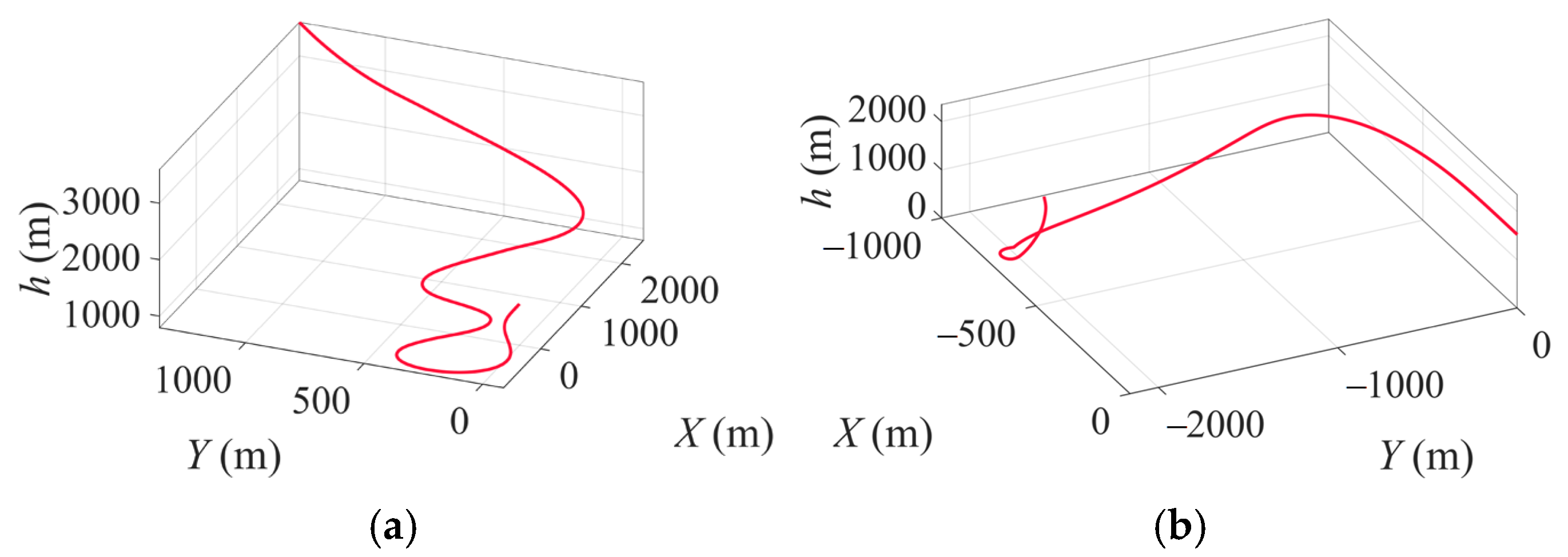
The attitude tracking signals for the snake-shaped and barrel roll maneuvers are illustrated in Figure 12. The tracking control law is designed by means of nonlinear dynamic inversion, with the control allocation algorithm adopting a cascaded generalized inverse method. In Figure 13a, the snake-shaped maneuver is configured with four high-agility transients; in comparison, the barrel roll maneuver in Figure 13b is designed to induce progressive control failure near t = 22   s , where μ denotes the roll angle of around the velocity vector axis. Figure 14 illustrates the trajectory curves of snake-shaped maneuvers and failed barrel roll maneuvers.

4.1. Comparative Simulations of the AMS and IAMS

To comparatively illustrate the distinct characteristics of the AMS, IAMS, and INAMS in computing the attainable moment set, detailed analyses were conducted at two timestamps, 24 s and 26 s, during the snake-shaped maneuver of the ICE aircraft. These timestamps were selected to compare the computational results when Φ 2 is convex with the non-convex form. Furthermore, comparative simulations between Φ 3 , computed by interpolation methods, and Φ 2 were performed to validate the accuracy of the INAMS, as demonstrated in Figure 15. The algorithm for “AMS” and “ AMS ” in Figure 15a was first proposed in [5] and has been used ever since. The “Interp” algorithm references the exhaustive enumeration method adopted in [22]. Specifically, it performs interpolation on 11 effectors within the ACS, followed by cubic fitting of the outermost interpolation points to generate the surface shown in the figure.
In Figure 15, subfigures (b) and (e) are magnified views of (a) and (d), respectively, focusing on the IAMS and INAMS. The convex polyhedra of the AMS in (a) and (d) are computed under the assumption of linear control effectiveness for the ICE vehicle, based on state variables at the current time step. Additionally, AMS is derived by substituting the AMS corresponding δ m top and δ m bot into Equations (20) and (21). In subfigures (a) and (d), the parallel planes in the AMS fail to form closed polyhedra and exhibit multiple overlapping intersections. This factor demonstrates that δ m top and δ m bot , computed by the AMS, violate the necessary conditions of the attainable moment set. Consequently, the AMS cannot reliably compute the nonlinear attainable moment set. Moreover, subfigures (c) and (f) depict the Φ 3 generated by means of uniform interpolation, where Δ δ = 0.2 δ ¯ δ _ between adjacent points remains constant. Theoretically, Φ 3 obtained by means of brute-force computation represents the nonlinear AMS with minimal numerical errors. Color mapping facilitates visual verification that the interpolated Φ 3 geometrically coincides with the vertices of Φ 2 . These results validate the feasibility and accuracy of the INAMS.
It should be noted that the linearity assumption in AMS computation does not hold in practice. This simplified premise is adopted solely to contrast the geometric distinctions between the AMS and the IAMS. As evidenced by the reduced volume metrics of the attainable moment set, the IAMS imposes more stringent aerodynamic constraints than the AMS. Figure 16 and Figure 17 provide flight-control-oriented comparative validation to further corroborate this conclusion.
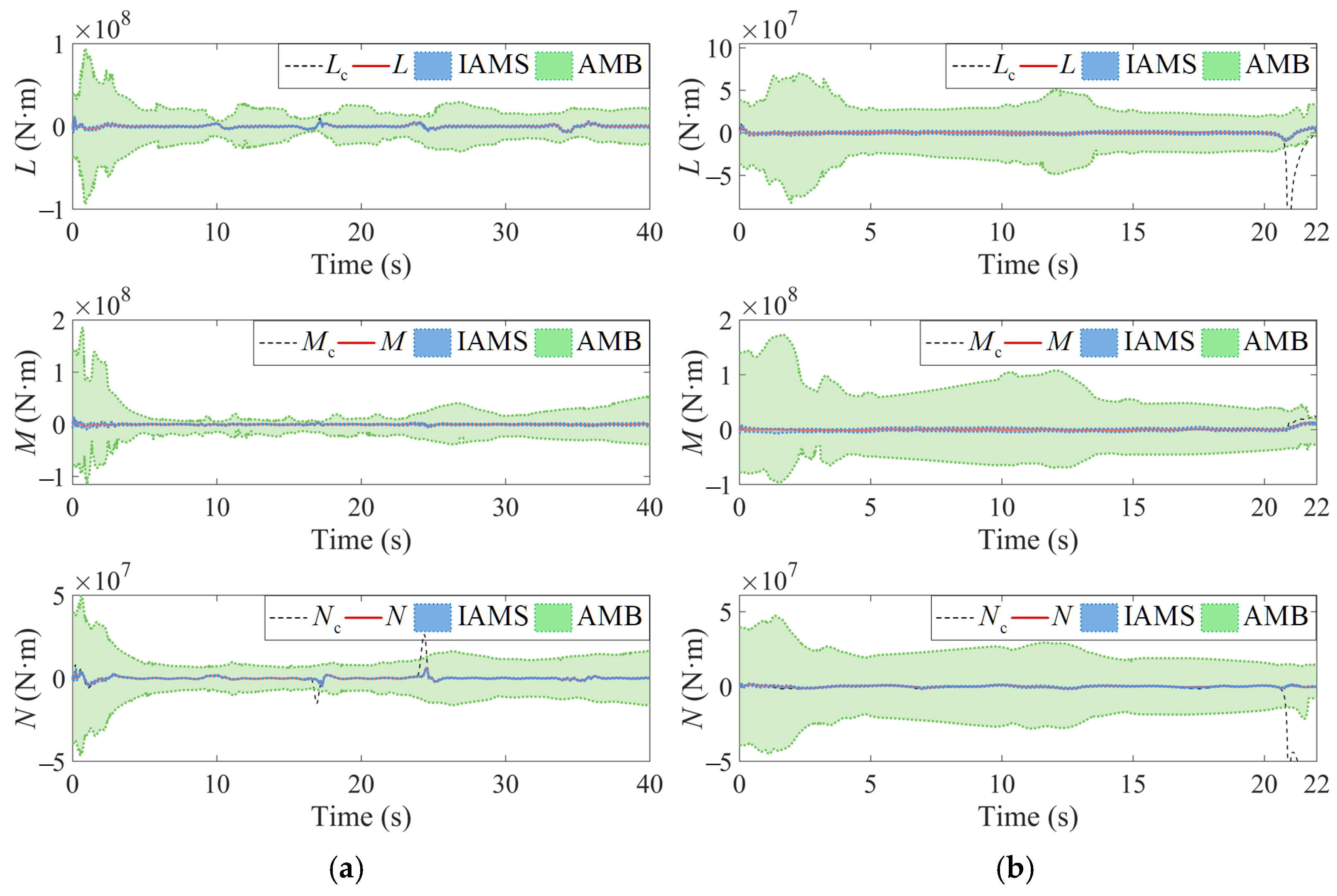
In Figure 16 and Figure 17, the green regions depict the AMS-Boundary (AMB) algorithm proposed in [23]; the AMB computes the envelope of the effective actions set constrained by deflection angles. It should be noted that the comparison objects in Figure 16, Figure 17 and Figure 18 are all envelopes of the effective actions set derived from dynamic control systems. In Figure 16, Figure 17 and Figure 18, the IAMS represents the envelopes of the effective actions set calculated by the methodology described in Section 3.1. Similarly, the INAMS in Figure 18 corresponds to the envelopes of the effective actions set obtained from the computational method described in Section 3.2.
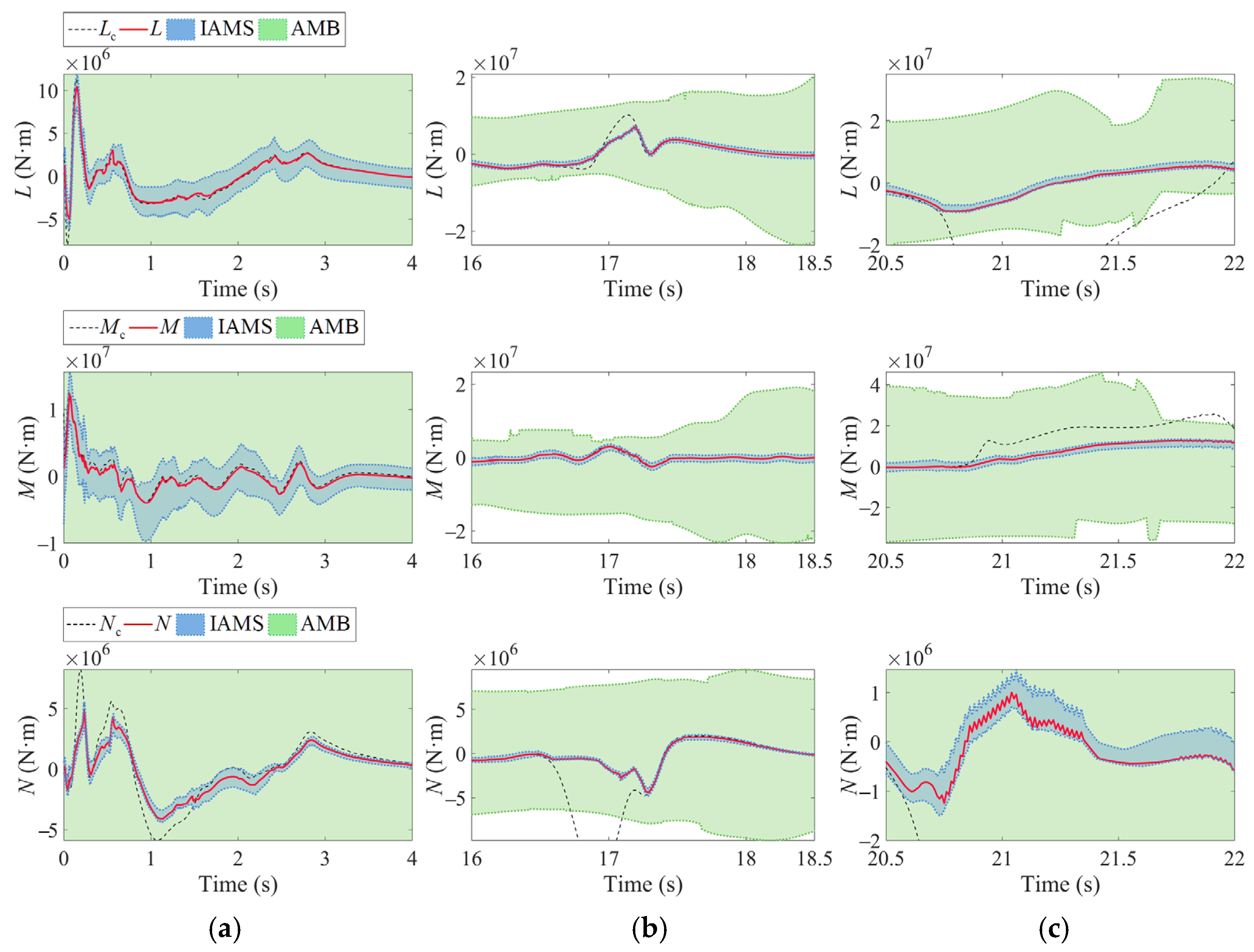
As shown in Figure 16, the envelopes of the effective actions set computed by the IAMS closely track the L , M , N signals at this scale compared to the AMB. Furthermore, during the periods of significant tracking errors in Figure 16a and control failure in Figure 16b, L c , M c , N c are bounded solely by the IAMS but remain unconstrained by the AMB. Therefore, the IAMS significantly outperforms the AMB in accuracy and dynamic fidelity for characterizing the effective actions set of the ICE aircraft. To provide a more intuitive analysis of the IAMS computational details, in Figure 17, we present zoomed-in tracking curves from specific regions illustrated in Figure 16. These magnifications explicitly capture the temporal evolution of the attainable moment set as simulation time t progresses. Given that t directly correlates with the dynamic variations in aircraft state variables, this approach effectively illustrates the evolution of the attainable moment set in response to state variations. The selection of Figure 17a,b, specifically, aims to highlight the critical simulation outcome where the constrained moments L c , N c exceed the IAMS boundaries, and yet remain within the AMB. The results presented in Figure 17c further demonstrate that, during control failure, the IAMS precisely defines the safety boundaries of the ICE aircraft.
The preceding analysis highlights the computational advantages of the IAMS. However, as shown in Figure 15b,d, the INAMS exhibits potential for enhanced precision over the IAMS. These figures highlight discrepancies between the IAMS and INAMS, which originate from vertex reposition. A critical distinction is that, while the IAMS maintains convexity in both subfigures, the INAMS in Figure 15d exhibits non-convex geometry. This observation implies that the IAMS calculations inherently neglect nonlinearity in ICE aircraft, particularly under non-monotonic aerodynamic conditions. These errors become significant when applied to non-convex INAMS geometries. The results further indicate that the INAMS, constructed through vertex reposition, can mitigate the nonlinearity of aerodynamic effectiveness in tailless UAVs. To verify this conclusion, Figure 18 in Section 4.2 provides further comparative analysis.

4.2. Comparative Simulations of the IAMS and INAMS

To enable a comparative analysis between the IAMS and the INAMS, in this subsection, we examine three representative segments from the snake-shaped and barrel roll maneuvers, highlighted by zoomed-in views in Figure 18.
In Figure 18a, when Δ L c , Δ N c exceed the effective actions set of the IAMS, the tracking curves of Δ L , Δ N violate the IAMS constraints at multiple points but remain within the INAMS. In Figure 18b,c, when the tracking curves of Δ L , Δ M , Δ N exhibit rapid oscillations, the effective actions set of the IAMS demonstrates reduced sensitivity compared to the INAMS. This finding confirms that the effective actions set of the INAMS provides a more accurate characterization of the dynamic maneuverability for ICE aircraft.
Furthermore, during control failure, as presented in Figure 18c, the INAMS provides a clearer and more accurate characterization of the safety boundaries. In fact, the results presented in Figure 18 reveal multiple instances where the IAMS boundaries exceed those of the INAMS. Synthesizing the above analysis, the red regions transgressing the blue INAMS boundaries result from the IAMS neglect of nonlinear effectors’ effectiveness, and such regions represent aerodynamically non-existent maneuvers for ICE in practice.
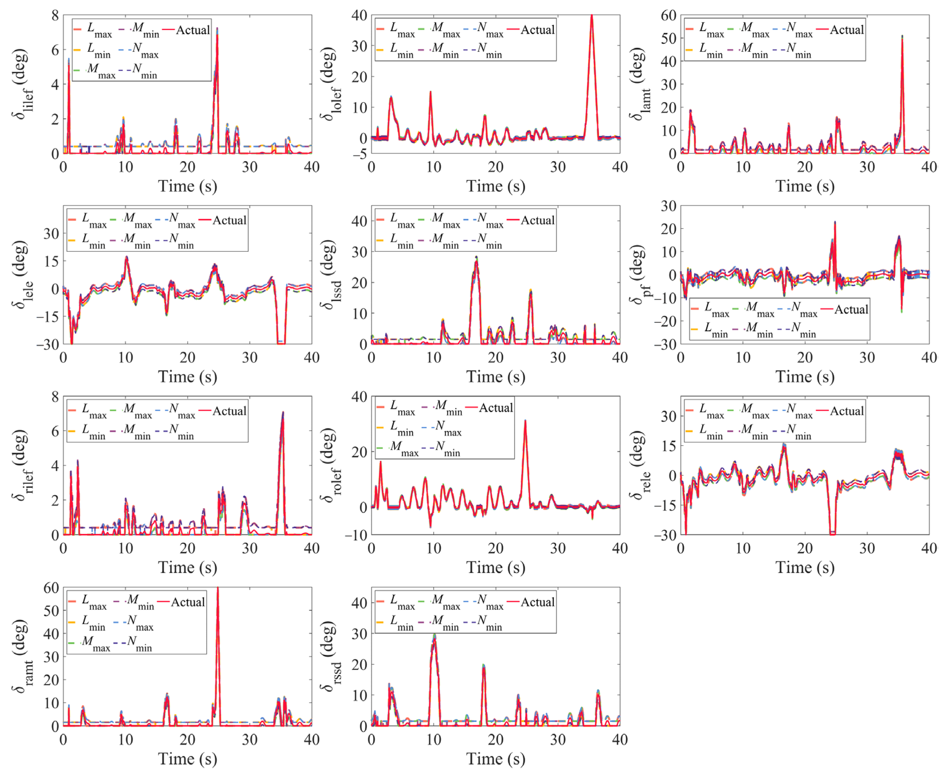
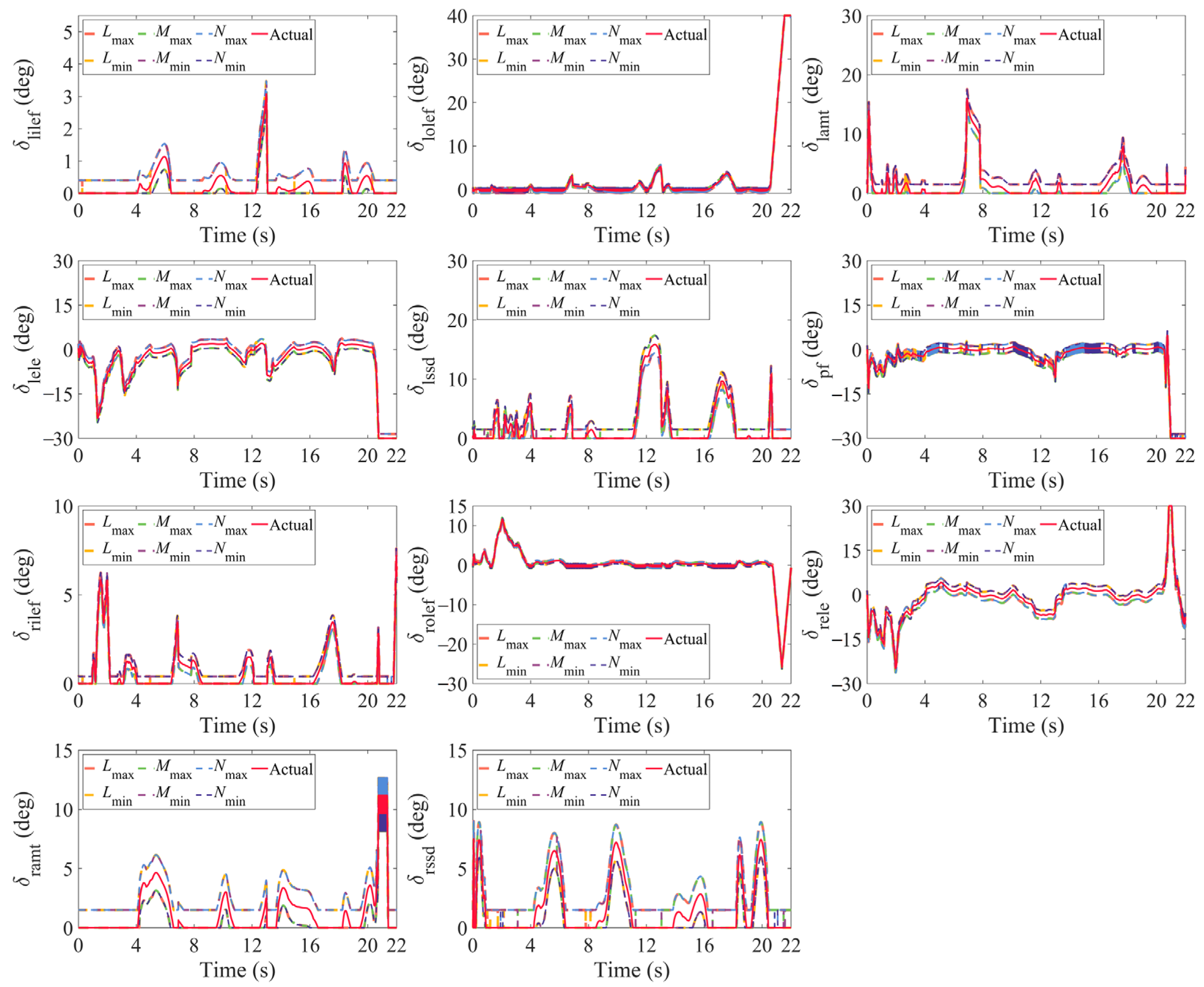
Lastly, it should be clarified that the IAMS and INAMS envelopes in Figure 16, Figure 17 and Figure 18 correspond to their respective effective actions set. For credibility, Figure 19 and Figure 20 present the effectors’ deflection curves corresponding to the effective actions set of IAMS and INAMS in the above analysis. Figure 19 shows the 11 effectors’ deflection curves corresponding to the snake-shaped maneuver and Figure 20 corresponds to the barrel roll maneuver. The red solid line represents the effectors’ deflection curves calculated by the control allocation algorithm in the closed-loop flight control. Our computational results demonstrate that the effective actions set accurately characterizes both the residual moment envelope and safety-critical flight boundaries of the ICE aircraft dictated by airframe and effectors’ dynamics. Thus, the feasibility of the effective actions set is empirically validated.

5. Conclusions

In this study, we propose an INAMS methodology for tailless UAVs, with rigorous validation of its effectiveness and reliability from the flight control perspective. The quantitative analysis and dynamic computation of the INAMS provide critical design foundations for flight control systems. By integrating control surface rate constraints into the admissible control set, the IAMS not only maps the dynamic characteristics of effectors, but also establishes a computationally feasible pathway for resolving non-convex boundaries in the nonlinear AMS. Based on the IAMS, vertex reposition, which combines local interpolation fitting and the stationary point method, effectively mitigates computational errors caused by nonlinear effectors’ effectiveness in the IAMS. Therefore, the INAMS algorithm is synthesized from the IAMS and the vertex reposition methodology. Thus, the feasibility of the effective actions set methodology is empirically validated. The results derived from the INAMS precisely characterizes the safe flight boundary and maneuverability envelope of tailless UAVs during flight control. In summary, while ensuring design objectives, the INAMS algorithm provides flight control systems with redundant moment space and residual moment capacity. This capability is expected to assist the flight control system in enhancing the maneuver margin and mission robustness of tailless UAVs. Future research objects should be to focus on the integrated codesign of the flight control system and the INAMS, incorporating the INAMS into closed-loop control architectures to optimize control efficacy.

Author Contributions

Conceptualization, L.H. and Y.W.; methodology, J.H.; software, L.H.; validation, J.H. and P.Z.; resources, Y.W.; data curation, L.H.; writing—original draft preparation, L.H.; writing—review and editing, Y.B. and P.Z.; visualization, L.H.; supervision, Y.B.; project administration, Y.B.; funding acquisition, Y.W. All authors have read and agreed to the published version of the manuscript.

Funding

This work was supported by the National Natural Science Foundation of China [grant number 62103439].

Data Availability Statement

Not applicable.

Acknowledgments

We extend our sincere appreciation for the comprehensive support provided by “The Youth Innovation Team of Shaanxi University”.

Conflicts of Interest

The authors declare no conflicts of interest.

References

  1. Zhu, J.; He, R.; Tang, G.; Bao, W. Pendulum Maneuvering Strategy for Hypersonic Glide Vehicles. Aerosp. Sci. Technol. 2018, 78, 62–70. [Google Scholar] [CrossRef]
  2. Yu, Z.; Li, Y.; Lv, M.; Pei, B.; Xu, W.; Bu, X. Fixed-Time Adaptive Fuzzy Fault-Tolerant Attitude Control for Tailless Aircraft Without Angular Velocity Measurements. IEEE Trans. Fuzzy Syst. 2024, 32, 2458–2470. [Google Scholar] [CrossRef]
  3. Lei, H.; Chen, B.; Liu, Y.; Lv, Y. Modified Kalman Particle Swarm Optimization: Application for Trim Problem of Very Flexible Aircraft. Eng. Appl. Artif. Intell. 2021, 100, 104176. [Google Scholar] [CrossRef]
  4. Lu, Z.; Hong, H.; Diepolder, J.; Holzapfel, F. Maneuverability Set Estimation and Trajectory Feasibility Evaluation for eVTOL Aircraft. J. Guid. Control Dyn. 2023, 46, 1184–1196. [Google Scholar] [CrossRef]
  5. Durham, W.C. Attainable Moments for the Constrained Control Allocation Problem. J. Guid. Control Dyn. 1994, 17, 1371–1373. [Google Scholar] [CrossRef]
  6. Varriale, C. Flight Mechanics and Performance of Direct Lift Control. Ph.D. Thesis, Delft University of Technology, Delft, The Netherlands, 2022. [Google Scholar]
  7. Kaloust, J.; Doman, D.B. Computing Trimmable Angle of Attack for Aircraft with Control Failures. In Proceedings of the 2003 IEEE Aerospace Conference Proceedings (Cat. No.03TH8652), Big Sky, MT, USA, 8–15 March 2003; IEEE: Big Sky, MT, USA, 2003; Volume 6, pp. 6_2801–6_2807. [Google Scholar] [CrossRef]
  8. Zhong, L. Contribution to Fault Tolerant Flight Control Under Actuator Failures. Ph.D. Thesis, INSA de Toulouse, Toulouse, France, 2014. [Google Scholar]
  9. Söpper, M.; Zhang, J.; Bähr, N.; Holzapfel, F. Required Moment Sets: Enhanced Controllability Analysis for Nonlinear Aircraft Models. Appl. Sci. 2021, 11, 3456. [Google Scholar] [CrossRef]
  10. Yu, Y.; Li, R.; Ji, W.; Lu, Z.; Tian, G. Refinements of the Dynamic Inversion Part of Hierarchical 4WIS/4WID Trajectory Tracking Controllers. SAE Int. J. Adv. Curr. Prac. Mobil. 2024, 6, 898–912. [Google Scholar] [CrossRef]
  11. Lu, Z.; Hong, H.; Schweighofer, F.; Holzapfel, F. Controllability Evaluation for VTOL Aircraft in Velocity Envelope: A Distance-Based Metric. J. Guid. Control Dyn. 2024, 47, 1620–1633. [Google Scholar] [CrossRef]
  12. Bolender, M.A.; Doman, D.B. Method for Determination of Nonlinear Attainable Moment Sets. J. Guid. Control Dyn. 2004, 27, 907–914. [Google Scholar] [CrossRef]
  13. Hu, Q.; Tan, X.; Akella, M.R. Closed-Loop-Based Control Allocation for Spacecraft Attitude Stabilization with Actuator Fault. J. Guid. Control Dyn. 2018, 41, 944–953. [Google Scholar] [CrossRef]
  14. Zhu, Z.; Guo, H.; Ma, J. Aerodynamic Layout Optimization Design of a Barrel-Launched UAV Wing Considering Control Capability of Multiple Control Surfaces. Aerosp. Sci. Technol. 2019, 93, 105297. [Google Scholar] [CrossRef]
  15. Zheng, F.; Liu, L.; Chen, Z.; Chen, Y.; Cheng, F. Hybrid Multi-Objective Control Allocation Strategy for Compound High-Speed Rotorcraft. ISA Trans. 2020, 98, 207–226. [Google Scholar] [CrossRef] [PubMed]
  16. Varriale, C.; Voskuijl, M. A Trim Problem Formulation for Maximum Control Authority Using the Attainable Moment Set Geometry. CEAS Aeronaut. J. 2022, 13, 251–266. [Google Scholar] [CrossRef]
  17. Pfeifle, O.; Fichter, W. Incremental Control Allocation with Axis Prioritization on the Boundary of the Attainable Control Set. In AIAA SCITECH 2023 Forum; American Institute of Aeronautics and Astronautics: National Harbor, MD, USA, 2023. [Google Scholar] [CrossRef]
  18. Pfeifle, O.; Fichter, W. Minimum Power Control Allocation for Incremental Control of Over-Actuated Transition Aircraft. J. Guid. Control Dyn. 2023, 46, 286–300. [Google Scholar] [CrossRef]
  19. Bolander, C.R.; Hunsaker, D.F.; Myszka, D.; Joo, J.J. Attainable Moment Set and Actuation Time of a Bio-Inspired Rotating Empennage. In AIAA SCITECH 2022 Forum; AIAA: San Diego, CA, USA, 2022. [Google Scholar]
  20. Wahler, N.F.; Varriale, C.; La Rocca, G. Impact of Control Allocation Methods on the Design of Control Surface Layouts for Box-Wing Aircraft under Flying Qualities Constraints. In AIAA AVIATION 2023 Forum; American Institute of Aeronautics and Astronautics: San Diego, CA, USA, 2023. [Google Scholar] [CrossRef]
  21. Zhang, J.; Söpper, M.; Holzapfel, F.; Zhang, S. Four-Dimensional Generalized AMS Optimization Considering Critical Engine Inoperative for an eVTOL. Aerospace 2024, 11, 990. [Google Scholar] [CrossRef]
  22. Jonasson, M.; Andreasson, J.; Jacobson, B.; Trigell, A.S. Global Force Potential of Over-Actuated Vehicles. Veh. Syst. Dyn. 2010, 48, 983–998. [Google Scholar] [CrossRef]
  23. Han, L.; Hu, J.; Wang, Y.; Cong, J.; Zhang, P. Design of Pseudo-Command Restricted Controller for Tailless Unmanned Aerial Vehicles Based on Attainable Moment Set. Drones 2024, 8, 101. [Google Scholar] [CrossRef]
  24. Stolk, A.R.J. Minimum Drag Control Allocation for the Innovative Control Effector Aircraft. Master’s Thesis, Delft University of Technology, Delft, The Netherlands, 2017. [Google Scholar]
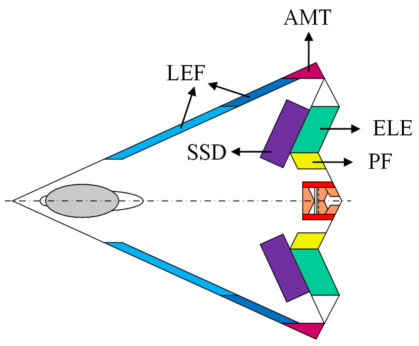
Figure 1. Top view of the ICE aircraft.
Drones 09 00585 g001
Figure 2. Nonlinear generation path from δ and state variables to C M .
Drones 09 00585 g002
Figure 3. Architecture diagram of a tailless UAV control system.
Drones 09 00585 g003
Figure 4. Schematic diagram of computational challenges in the nonlinear AMS under the R 3 R 2 mapping scenario.
Drones 09 00585 g004
Figure 5. Schematic diagram of the admissible control set (ACS).
Drones 09 00585 g005
Figure 6. IAMS with n = 4 .
Drones 09 00585 g006
Figure 7. Variation in the aerodynamic moment coefficient with δ lamt and α . (a) Roll moment coefficient. (b) Pitch moment coefficient. (c) Yaw moment coefficient.
Drones 09 00585 g007
Figure 8. Spatial relationship between Φ 1 and Φ 2 .
Drones 09 00585 g008
Figure 9. Effect of non-monotonicity.
Drones 09 00585 g009
Figure 10. Effect of vertex repositioning.
Drones 09 00585 g010
Figure 11. Schematic of vertex selection for the INAMS along three axes. (a) Δ C L -axis projection view; (b) Δ C M -axis projection view; (c) Δ C N -axis projection view.
Drones 09 00585 g011
Figure 12. Simulation block diagram.
Drones 09 00585 g012
Figure 13. Attitude tracking curves for μ , α , β .
Drones 09 00585 g013aDrones 09 00585 g013b
Figure 14. Simulink trajectory of tailless UAVs (O-XYh represents the geodetic coordinate system). (a) Snake-shaped maneuver. (b) Failed barrel roll maneuver.
Drones 09 00585 g014
Figure 15. Comparison of AMS, IAMS, and INAMS. (a) 24 s AMS and IAMS; (b) 24 s IAMS and INAMS (convex); (c) 24 s INAMS and interpolation; (d) 26 s AMS and IAMS; (e) 26 s IAMS and INAMS (non-convex); (f) 26 s INAMS and interpolation.
Drones 09 00585 g015aDrones 09 00585 g015b
Figure 16. Comparison of L , M , N and effective actions set. (a) Snake-shaped maneuver. (b) Barrel roll maneuver.
Drones 09 00585 g016
Figure 17. Regional comparison of L , M , N and effective actions set. (a) Snake-shaped 0~4 s. (b) Snake-shaped 16~18.5 s. (c) Barrel roll 20.5~22 s.
Drones 09 00585 g017
Figure 18. Regional comparison of Δ L , Δ M , Δ N and effective actions set. (a) Snake-shaped 0~0.8 s. (b) Snake-shaped 16.4~17.3 s. (c) Barrel roll 20.5~22 s.
Drones 09 00585 g018
Figure 19. Effectors’ deflection of snake-shaped maneuver.
Drones 09 00585 g019
Figure 20. Effectors’ deflection of barrel roll maneuver.
Drones 09 00585 g020
Table 1. ICE aircraft simulation parameters.
ParametersValueUnit
b ref 37.50 ft
c ¯ 28 . 75 ft
S ref 808.60 c
x ac 38 . 84 % c ¯ ft
x cg 37 . 90 % c ¯ ft
Table 2. Limits of effectors.
EffectorsAngle Limits (deg)Angle Rate Limits (deg/ms)
lilef[0, 40][−0.04, 0.04]
lolef[−40, 40][−0.04, 0.04]
lamt[0, 60][−0.15, 0.15]
lele[−30, 30][−0.15, 0.15]
lssd[0, 60][−0.15, 0.15]
pf[−30, 30][−0.15, 0.15]
rilef[0, 40][−0.04, 0.04]
rolef[−40, 40][−0.04, 0.04]
ramt[0, 60][−0.15, 0.15]
rele[−30, 30][−0.15, 0.15]
rssd[0, 60][−0.15, 0.15]
Disclaimer/Publisher’s Note: The statements, opinions and data contained in all publications are solely those of the individual author(s) and contributor(s) and not of MDPI and/or the editor(s). MDPI and/or the editor(s) disclaim responsibility for any injury to people or property resulting from any ideas, methods, instructions or products referred to in the content.