Article

Model-Free UAV Navigation in Unknown Complex Environments Using Vision-Based Reinforcement Learning

1
Graduate School of Engineering, Chiba University, 1-33 Yayoi-cho, Inage-ku, Chiba 263-8522, Japan
2
Autonomous, Intelligent, and Swarm Control Research Unit, Fukushima Institute for Research, Education and Innovation (F-REI), Fukushima 979-1521, Japan
*
Author to whom correspondence should be addressed.
Drones 2025, 9(8), 566; https://doi.org/10.3390/drones9080566
Submission received: 25 June 2025 / Revised: 31 July 2025 / Accepted: 11 August 2025 / Published: 12 August 2025

Abstract

Autonomous UAV navigation in unknown and complex environments remains a core challenge, especially under limited sensing and computing resources. While most methods rely on modular pipelines involving mapping, planning, and control, they often suffer from poor real-time performance, limited adaptability, and high dependency on accurate environment models. Moreover, many deep-learning-based solutions either use RGB images prone to visual noise or optimize only a single objective. In contrast, this paper proposes a unified, model-free vision-based DRL framework that directly maps onboard depth images and UAV state information to continuous navigation commands through a single convolutional policy network. This end-to-end architecture eliminates the need for explicit mapping and modular coordination, significantly improving responsiveness and robustness. A novel multi-objective reward function is designed to jointly optimize path efficiency, safety, and energy consumption, enabling adaptive flight behavior in unknown complex environments. The trained policy demonstrates generalization in diverse simulated scenarios and transfers effectively to real-world UAV flights. Experiments show that our approach achieves stable navigation and low latency.

1. Introduction

1.1. Background

Driven by continuous technological progress [1,2], unmanned aerial vehicles (UAVs) have now been integrated into many aspects of everyday life. For example, UAVs are extensively used for aerial photography [3], reconnaissance missions [4], and rescue operations [5], among other applications. Although manually controlled UAVs are effective for routine tasks, their extensive reliance on human intervention renders them inefficient and costly for large-scale operations [6]. Therefore, extensive research has been directed toward developing autonomous flight systems for UAVs, especially for challenging missions, to enhance operational flexibility. This is particularly critical in complex mission environments such as forest rescues and disaster relief operations. Traditional path planning methods mostly rely on pre-built environment models, high-cost online planning, or manually designed features, which are difficult to simultaneously meet the requirements of drones for real-time, lightweight in unknown and complex environments [7]. Therefore, developing a novel navigation system that does not rely on pre-constructed maps and can adapt to unknown complex environments is necessary, especially to address the growing demand for lightweight, scalable, and highly responsive UAV navigation solutions that can maintain safety and efficiency in unknown complex environments. This study aims to address this gap by exploring an end-to-end, vision-based reinforcement learning framework to eliminate the need for conventional mapping and decoupled planning pipelines.

1.2. Review of Related Works

Literature on UAV autonomous navigation algorithms is classified into conventional, rule-based techniques, and those driven by machine learning. Conventional autonomous navigation systems include an environmental perception and positioning module, a flight pathway planning and decision module, and a UAV control module [8]. The perception and positioning module gathers data from sensors (e.g., radar, cameras, and global positioning system) and employs mapping techniques, such as simultaneous localization and mapping (SLAM), to deliver location and environmental information. The flight pathway planning and decision-making module leverages data from the perception and localization system to compute the most efficient flight route from the current position to the destination, whereas the control module performs the mission. These modules cooperate to achieve UAV navigation, where the perception, planning, and control modules detect obstacles, compute an obstacle-avoiding trajectory, and produce motor commands, respectively. Hening et al. implemented a SLAM-based navigation algorithm that employed a light identification detector and ranging (LiDAR) for local positioning and an adaptive extended Kalman filter for estimating the speed and position of the UAV; however, the performance of this algorithm degraded in unknown complex environments [9]. Kumar et al. proposed an indoor UAV navigation solution by combining low-cost LiDAR and inertial measurement unit (IMU) data through scan-matching and Kalman filtering for 3D position estimation. Although this approach was effective for SLAM, it suffered from limited LiDAR stability and high computational demands in challenging environments [10]. Other studies [11,12,13] also developed SLAM-based methods to achieve UAV navigation.
However, conventional SLAM approaches decouple perception, planning, and control while depending on precise sensor data and handcrafted feature descriptors [14], which results in coordination difficulties, high computational overhead, and limited adaptability to unknown complex environments. Researchers also explored alternative approaches such as perception-based obstacle avoidance [15,16,17] and filtering-based positioning techniques [18,19,20]; however, perception-based obstacle avoidance methods were vulnerable to recognition errors and reaction delays when confronted with unknown complex environments, which heightened collision risks. Similarly, filtering-based positioning methods were found to be highly sensitive to environmental variations and noise, which exacerbated positioning errors and undermined navigation accuracy.
Conversely, deep reinforcement learning (DRL) algorithms reached a level of maturity where they could effectively tackle a wide range of sequential decision-making tasks, including Go, video games, and autonomous driving [21,22,23]. Consequently, a growing number of studies have explored the application of reinforcement learning to address navigation challenges for harnessing its autonomous learning capabilities for more flexible and efficient decision making in unknown complex environments. Faust et al. proposed a method called PRM-RL, where they combined sampled path planning and reinforcement learning methods for long-distance navigation tasks. Although the PRM-RL improved the task completion rate of indoor navigation and aerial cargo transportation, the disadvantages of this method were its reliance on pre-generated path planning maps and inability to respond flexibly to real-time changes in unknown complex environments [24]. Pham et al. combined proportional–integral–derivative (PID) control with a Q-learning-based reinforcement learning approach to achieve UAV navigation, demonstrating the potential of reinforcement learning for UAV control. However, only the position of the UAV was used as the input information, and the actions were discrete [25]. Loquercio et al. used deep learning with car visual data to guide UAVs in urban environments; however, their method lacked clearly defined goals [26]. These studies highlight the potential of deep learning approaches to leverage rich visual information for enhancing UAV navigation in complex, unknown environments [27]. Chen et al. employed RGB images as input for a Q-learning algorithm to generate control commands, achieving basic navigation and obstacle avoidance behaviors [28]; however, this approach struggled under challenging lighting or occlusion conditions. Polvara et al. utilized camera inputs and deep Q-networks to facilitate UAV landing; however, their method did not consider the effect of interfering obstacles in unknown environments, and the actions were discrete [29]. Kalidas et al. designed a visual input-driven reinforcement learning algorithm within the AirSim environment; however, their validation was confined to simulation scenarios and suffered from a discretized action space [30]. AlMahamid et al. proposed VizNav, a deep reinforcement learning-based modular system designed for autonomous navigation in dynamic 3D spaces; however, the dependence of this system on depth data could limit its adaptability in fast-changing environments [31], and their final UAV control module executed commands directly based on target values generated by the network. Xu et al. employed the MPTD3 algorithm, integrating multiple replay buffers and truncated gradient techniques to model UAV states and actions in a continuous space, thereby accelerating training convergence. Their method primarily targets obstacle avoidance and target tracking while optimizing path efficiency [32]. However, it focuses solely on single-objective reinforcement learning, and the training process remains heavily reliant on large volumes of data, resulting in limited generalization capability. Yang et al. proposed a demonstration-guided reinforcement learning method (SACfD) to enable mapless UAV navigation by leveraging demonstration trajectories and maximum entropy learning [33]; however, their approach was highly dependent on pre-recorded expert data and lacked multi-objective optimization capability for balancing safety, efficiency, and energy consumption. Zhao et al. designed a data-driven offline reinforcement learning framework with Q-value estimation to improve UAV path planning robustness [34]. But this method relied heavily on offline datasets and showed limited adaptability when faced with real-time environmental changes or unseen conditions. Sun et al. employed causal reinforcement learning to construct an end-to-end UAV obstacle avoidance strategy, which enhanced reaction speed and situational awareness [35]. Nevertheless, the method focused exclusively on safety optimization, neglecting considerations such as path efficiency and energy-aware navigation in complex environments. Amala et al. applied classic Q-learning within a discretized grid environment to achieve UAV dynamic obstacle avoidance and path planning [36]. While effective in reducing path length, the method lacked continuous control resolution and failed to account for robustness or energy efficiency under real-world conditions. Wang et al. used a DPRL framework with privileged visual data to speed up training and achieve efficient simulated obstacle avoidance, but it depends on unavailable data and has no real-world tests [37]. Samma H et al. used a two-stage DQN plus Faster R-CNN for perception to boost simulated flight performance, but ran only in a static simulation, with no real-world trials, and still decoupled perception-control causing latency and limited generalization [38]. At the same time, Shao et al. proposed a finite-time learning-based optimal elliptical encircling controller for UAVs, integrating a robust steady-state control protocol with a single-critic reinforcement learning framework. While the framework enhances robustness in uncertain environments, its reliance on online approximation of the Hamilton-Jacobi-Bellman (HJB) equation introduces non-trivial computational overhead, potentially hindering real-time deployment on resource-limited UAV platforms [39]. Li et al. further proposed a safety-certified formation controller combining a single-critic ADP framework with high-order control barrier functions (HO-CBFs). This architecture decouples safety enforcement from learning, enabling collision-free formation in dynamic environments with fixed-time weight convergence. While the HO-CBFs online solving of high-order Lie derivatives introduces significant computational overhead for multi-agent systems, particularly in dense obstacle fields. Moreover, the fixed-time convergence of neural weights relies on precise system dynamics models for HO-CBF construction, reducing robustness against unmodeled disturbances. The fixed-time learning accelerates convergence but still faces latency in real-time obstacle avoidance due to iterative QP solving for safety constraints [40]. On the other hand, most reinforcement learning-based approaches convert navigation outputs into motor commands via controllers, commonly using PID, sliding mode, backstepping, fuzzy control, adaptive critic, disturbance observer control, or model predictive control [41,42,43,44,45,46,47]. An overview of the related studies discussed above is presented in Table 1 for comparative analysis.
Based on the above discussion, the following common challenges were identified for the autonomous navigation of UAVs in complex and unknown environments:
  • Mapping difficulty and low robustness: Conventional SLAM or mapping-based navigation methods suffer from significant challenges related to real-time operation and robustness because of the dense and irregular distribution of obstacles. First, building high-quality maps under conditions such as dynamic lighting is difficult. Second, the map update process requires high computing resources, which affects navigation efficiency [48,49].
  • Poor module integration and response delays: The separation and coordination problems between multiple modules (perception, planning, and control) often lead to system response delays, which increase the risk of collisions [50,51].
  • Single-objective optimization and low flexibility: Conventional navigation algorithms optimize a single goal, and although the local planner combines obstacle avoidance functions, these algorithms rely on manually adjusted fixed weights to implement multicriteria cost functions. This rigidity results in the trade-off between path efficiency, energy consumption, and safety in unknown complex environments [52,53].
Therefore, developing a UAV navigation framework that can minimize reliance on full-map reconstruction and precise sensors, tightly integrate perception-to-control within a single policy network, and employ depth sensing with a multi-objective reward to achieve adaptive, real-time flight decisions is urgently required. We present our deep vision-based reinforcement learning method that addresses these gaps by directly mapping onboard depth images and UAV states to control commands, which helps ensure responsiveness and robustness in unknown complex environments.

1.3. Proposed Method and Contribution

In response to the aforementioned challenges commonly encountered in unknown complex environments, such as the difficulty of real-time mapping, system latency caused by loosely coupled modules, and inflexibility of conventional navigation algorithms in balancing multiple objectives, a vision-based reinforcement learning method is proposed in this paper to generate end-to-end instructions for UAV navigation and obstacle avoidance. Unlike conventional SLAM or planning-based approaches, this method overcomes the requirement for pre-constructed maps and extensive environment modeling by directly mapping onboard depth image data and UAV state information to navigation commands through a policy network, significantly enhancing real-time responsiveness and system integration. In this architecture, tasks such as global path planning, heading control, and position regulation are handled by the policy network, whereas low-level execution tasks such as attitude and angular velocity control are delegated to the PID controller. This tightly integrated control framework effectively addresses the latency in conventional perception-planning-control pipelines. Moreover, the system improves robustness under dynamic lighting and complex geometric occlusions using depth images rather than RGB data. The policy network is trained using a multi-objective reward function that simultaneously considers path efficiency, safety, and energy consumption, enabling adaptive decision making in unknown complex environments. The proposed method provides a flexible and scalable solution for UAV navigation in environments where conventional methods struggle to maintain reliability and efficiency.
The key contributions of this paper are outlined below:
  • A UAV navigation architecture based on vision-driven reinforcement learning is proposed. Unlike conventional methods, the proposed architecture operates without map construction. Furthermore, it integrates a convolutional network with a policy network and considers the real-time status information of UAV and depth images as input, thereby enabling it to replace conventional path planning algorithms and position controllers. Moreover, it effectively mitigates response delays by avoiding the separation and coordination issues commonly found in modular systems. Additionally, the proposed architecture enables UAVs to autonomously adapt their flight paths and navigation strategies in unknown complex environments with low computational complexity, enhancing real-time responsiveness and maneuverability.
  • We design a multifactor reward function that simultaneously considers target distance, energy consumption, and safety to address the limitations of single-objective optimization employed in conventional navigation algorithms. This multifactor reward formulation enables the UAV to learn more flexible and balanced navigation strategies, enhancing overall performance while reducing the risk of collisions in unknown complex environments.
  • The proposed policy is trained and optimized by constructing multiple simulation environments with different obstacle distributions and lighting conditions. The trained policy does not require prior map generation, and its output can be directly applied to UAV navigation, thereby achieving successful flight in simulated and real environments, which demonstrates the practical feasibility and robustness of the proposed method. The experimental process is detailed in [54], and the corresponding code is available in [55].
The rest of this paper is organized as follows: Section 2 presents an overview of the system architecture and the components of the UAV controller. Section 3 details the navigation approach, including the deep network architecture and the reward function. Section 4 presents the experimental setup and the analysis of the results. Finally, Section 5 provides a summary of the key findings, discusses the limitations of the current work, and explores potential challenges for future research.

2. System Architecture

Figure 1 shows the overall system architecture. The actor network (red line in Figure 1) serves as the core module of the proposed navigation system, and its primary function is to generate control commands based on input data, which enables the UAV to perform autonomous navigation and control tasks. The actor network effectively combines navigation algorithms with position control functions. The system input comprises depth images acquired by the onboard camera and several state parameters provided by the UAV, which include yaw angle, velocity, and position. The UAV cannot perceive obstacles to its left and right because of its reliance on a forward-facing camera, and therefore, the network outputs are limited to the target forward velocity and target yaw angular velocity. Once the control commands are generated, they are transmitted to the underlying speed, attitude, and angular velocity controllers, which produce precise motor control signals. This process enables autonomous navigation and the efficient control of the UAV.
Figure 2 shows the control architecture of the UAV, which makes it highly maneuverable and capable of performing six degrees of freedom (DoF) motion through coordinated control of its four rotors. These six DoFs include three-dimensional translational ( P o s = [ X , Y , Z ] T ) and rotational motions ( R o t = [ α , β , ψ ] T ) about the three principal axes, where α , β , and ψ represent the roll angle, pitch angle, and yaw angle of the UAV, respectively. Each motor ( M 1 , M 2 , M 3 , M 4 ) generates a corresponding thrust force ( T 1 , T 2 , T 3 , T 4 ) via its rotor. These thrust forces are responsible for maintaining the altitude of the UAV and are crucial for controlling its attitude and position through coordinated modulation. The controller effectively compensates for external disturbances and achieves stable and responsive flight performance by precisely adjusting the thrust produced by each motor.
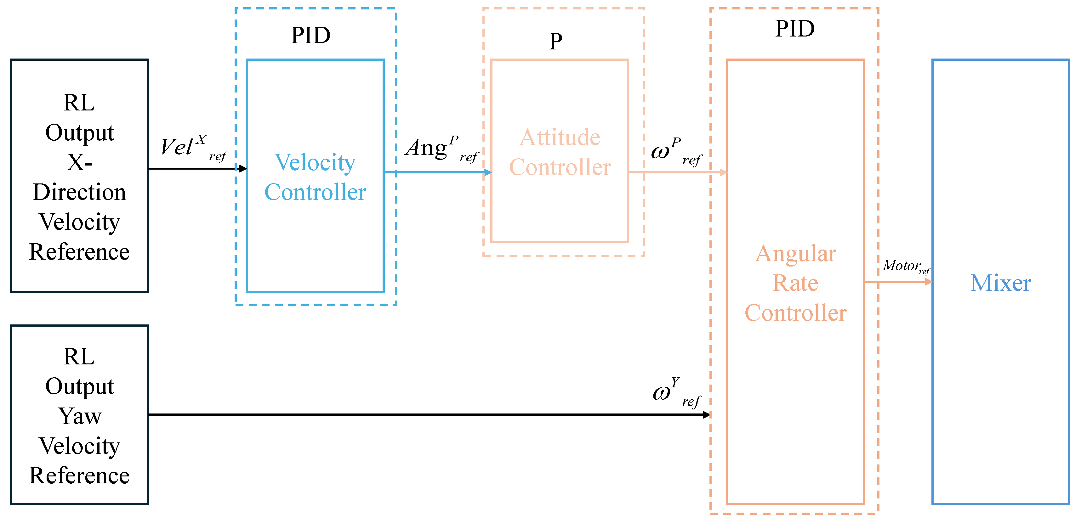
Figure 3 illustrates the hierarchical controller architecture adopted in this study for the UAV system. The PID controller is used to adjust the system output as shown in Equation (1).
u ( t ) = K p e ( t ) + K i 0 t e ( τ ) d τ + K d d e ( t ) d t
where e ( t ) represents the tracking error between the reference input and system output, and K p , K i , and K d represent the proportional, integral, and derivative gains, respectively.
At the top layer, the reinforcement learning module generates reference commands for lateral and yaw angular velocities, which are then transmitted to the underlying low-level controller. The low-level controller must stabilize the attitude and perform precise control adjustments. Furthermore, it ensures that the UAV can rapidly respond to external disturbances while accurately following the velocity commands issued by the high-level controller. Within this architecture, the velocity control layer determines the desired attitude using a PID controller. Subsequently, this target attitude is used by the attitude controller, which applies a P controller to adjust the orientation of the UAV. The angular velocity controller employs a full PID strategy to convert the desired attitude into corresponding angular velocity commands. Finally, a mixer assigns these control signals to individual motors, coordinating rotor thrusts to comprehensively control the motion and attitude of the UAV. This hierarchical architecture enables a clear separation of responsibilities, i.e., low-level controllers handle thrust and attitude control with high precision, whereas high-level controllers focus on navigation and position regulation. This modularity enables the UAV to operate efficiently even in unknown and complex environments.

3. Navigation Method

The previous section provided a detailed description of the low-level controller, designed within the framework of a newly introduced autonomous navigation system for UAVs operating in unknown and complex environments.
This section presents the high-level navigation module based on reinforcement learning, including the network architecture, the definition of state-action spaces, and the construction of the reward mechanism, which collectively establish the foundation for deriving an effective navigation policy.
Figure 4 presents the network structure built on the actor–critic framework, which facilitates fully autonomous path planning for UAVs operating in unknown complex environments.

3.1. Navigation Policy Structure

The UAV explores the environment by performing stochastic actions at the beginning of the training steps. Subsequently, it learns by interpreting the received reward signals as feedback from these interactions. The policy is iteratively updated to maximize expected returns across multiple episodes, where each episode consists of a sequence of interactions.
In every episode, the UAV receives and collects sensory inputs comprising depth images and the state data of the UAV (such as the position, velocity, and yaw angle), which are provided to the actor and critic networks for decision making and policy evaluation. The actor network maps the current state and observed environment conditions to corresponding control actions, specifically, the yaw angular velocity and forward velocity. In parallel, the evaluation network assesses the effectiveness of the current decision-making strategy to generate future updates.
Training stability and sampling efficiency are enhanced using a memory buffer to retain historical state-action-reward transitions, which are periodically sampled to update the policy and value estimators.
To assess the relative improvement of a selected action over the baseline state value during policy optimization, an advantage function is employed. As shown in Equation (2).
A ˜ π ( s , a ) = Q π ( s , a ) V α k ( s )
where Q π ( s , a ) denotes the action-value estimate, quantifying the expected future reward from state s upon taking action a under policy π . Then V α k ( s ) is the state-value estimate produced by the critic network parameterized by α k . Modified advantage function A ˜ π ( s , a ) guides the actor network in refining the policy by emphasizing actions that yield higher-than-expected returns.
To ensure stable and conservative policy updates, Proximal Policy Optimization (PPO) introduces a clipped surrogate objective that restricts the magnitude of policy changes. The updated policy parameters θ k + 1 are obtained by maximizing the following objective, as presented in Equation (3).
θ k + 1 = arg max θ 1 | D k | N τ D k t = 0 N min r t ( θ ) A ˜ π θ k ( s t , a t ) , g ˜ ( ϵ , A ˜ π θ k ( s t , a t ) )
where r t ( θ ) = π θ ( a t | s t ) π θ k ( a t | s t ) represents the ratio of probabilities between the updated and previous policies, A ˜ π θ k ( s t , a t ) represents the estimated advantage under the old policy π θ k .
The clipping function g ˜ ( ϵ , A ) is defined in Equation (4):
g ˜ ( ϵ , A ) = ( 1 + ϵ ) A , if A 0 , ( 1 ϵ ) A , if A < 0
where ϵ is a hyperparameter that constrains the update step size.
This clipping mechanism ensures that policy updates remain within a controlled range: if the estimated advantage A ˜ is positive, the probability ratio is clipped to 1 + ϵ ; if negative, it is clipped to 1 ϵ . By preventing overly aggressive updates, this technique enhances training stability and avoids performance degradation due to large policy shifts.
Unlike the actor network, which focuses on policy optimization, the critic network learns by adjusting its output to closely match a target value, minimizing prediction error. Gradient descent is applied to update the critic’s parameters by reducing the following loss, as illustrated in Equation (5).
α k + 1 = arg min α 1 | D k | N τ D k t = 0 N V α ( s t ) R ^ t 2
where V α ( s t ) denotes the value function estimated by the critic network parameterized by α , and R ^ t represents the target return, typically obtained from experience replay or temporal-difference bootstrapping.
By minimizing this loss, the critic progressively refines its value estimates, thereby enabling more accurate evaluations of the current policy. This improved feedback mechanism enhances the actor’s policy updates and contributes to more effective and stable UAV navigation in unknown complex environments.

3.2. Design of State and Action Spaces

This study employs a vision-based reinforcement learning framework, and therefore, a depth image captured by a forward-facing camera instead of an RGB image is used as the input to the network. Although RGB images contain richer features such as color and texture, they are not essential for the navigation task considered in this work. For our UAV navigation task, the primary objective is obstacle avoidance, which relies more on understanding spatial structure than on recognizing appearance. Depth images provide direct information about the geometry of the environment, including the shape, size, and relative distance of surrounding obstacles, and this enables the agent to learn effective obstacle avoidance behavior. Furthermore, compared with using RGB images directly, depth images can significantly reduce the dimensionality and complexity, which simplifies the architecture and improves training efficiency without compromising navigational performance.
However, using only the depth image as the state input primarily enables the learning of obstacle avoidance behavior, while the navigation task also requires the UAV to reach the target point safely. Therefore, this paper additionally incorporates the UAV’s state information into the input.
The state information of the UAV is combined with the high-dimensional features extracted from the depth image by the convolutional neural network (CNN) to form the input of a deeper policy network. This design is intended to help the model learn navigation strategies more effectively. To simplify the task, the height of the target point is assumed to remain constant, and the default value is set to 2 m so that the UAV needs to only reach the specified coordinate position on the two-dimensional x–y plane to complete the task. The design of the state space is illustrated in Figure 5.
The internal state information of the UAV and the depth image are fused through two distinct branches, as explained below.
As shown in Figure 6, the first branch is constructed using a CNN. Input depth images of size 192 × 192 × 4 are used, where the four channels correspond to the current depth image and depth images from the previous three time steps, respectively. This multiframe input design enables the network to capture dynamic environmental changes and the movement trajectory of the UAV, which promotes a better understanding of scene continuity.
A feature map of size 8 × 8 × 32 is produced after feature extraction through a four-layer convolutional network; this feature map is then flattened into a 2048-dimensional vector. This CNN branch is responsible for learning environmental features from depth images.
The second branch includes a fully connected network that fuses the image features with continuous state information. A six-element vector describing the present condition of the UAV is fed into this branch. Finally, concatenated state and image features are fed into the policy network for decision making.
The UAV only has a forward-facing depth camera, and therefore, this paper selects the angular of the z-axis and the velocity of the X-axis as the action space of this experiment (Figure 7). In Figure 7, they are represented as action[0] and action[1], respectively.
Thus, the generation of action commands relies on a policy network. Our framework can eliminate the need for separate map building, feature extraction, and path replanning modules by unifying the perception, planning, and control modules into an end-to-end policy network. During inference, only a single forward pass through the actuator network is required to generate velocity and yaw commands, which helps avoid inter-module communication overhead and expensive intermediate computations. The delay is within 28 ms from the state input to the output of the control target. Compared with the conventional perception-planning-control process, the proposed system significantly reduces decision latency and computational complexity, thereby enabling real-time, responsive drone navigation in unknown complex environments.

3.3. Design of the Reward Function

The effectiveness of learning autonomous navigation depends on the structure of the reward function. In this study, the reward function is designed to promote progress towards the target while penalizing unnecessary or premature obstacle avoidance actions and collisions to facilitate the rapid and efficient movement of the UAV towards the target point. Positive rewards are granted for successful obstacle avoidance, whereas collisions incur a severe penalty. The sampling process is terminated in the event of a collision, and the UAV receives the highest reward if it successfully reaches the target location.
In this study, the reward function is formulated considering the following factors: horizontal distance separating the UAV from the target location, angle ω between the heading of the UAV and the direction of the target, and the x-axis speed V x of the UAV. The reward function is formulated to include multiple components that consider these factors. The reward function is defined as shown in Equation (6).
R t = w 1 , w 2 , w 3 , w 4 , w 5 , w 6 , w 7 d t d t 1 ψ t ψ goal 1 { no obstacle } | ψ t ψ t 1 | 1 { obstacle detected } 1 { avoid success } | V x t 2 V x t 1 2 | 1 { crash } 1 { arrive }
where the reward at time t can be concisely written as the inner product of the weight vector w = [ w 1 , w 2 , w 3 , w 4 , w 5 , w 6 , w 7 ] = [ 0.5 , 0.8 , 0.05 , 0.3 , 3 , 5 , 5 ] and a feature vector, whose components are, in order, the reduction in the Euclidean distance to the target d t d t 1 . We can determine the presence of obstacles in front and whether the drone is at risk of collision based on the front depth data detected by the depth camera. The drone is considered to be in danger if the minimum front depth value is less than or equal to 0.28 m. This state is defined as a collision. Furthermore, we can determine whether the drone successfully avoided obstacles by analyzing the changes in depth values between consecutive frames. Therefore, we obtain the definition of the following feature vectors:
When no obstacle is detected, a larger heading error ψ t ψ goal results in a greater penalty. When an obstacle is detected, a greater yaw change | ψ t ψ t 1 | results in a greater reward, thereby promoting effective obstacle avoidance operations. When the drone avoids a previously detected obstacle successfully, 1 { avoid success } is equal to 1, which yields a positive reward. The absolute change in the square of the forward speed | V x t 2 V x t 1 2 | is used to penalize sudden acceleration or deceleration to promote an energy-efficient, smooth flight. If a collision occurs, the indicator 1 { crash } is equal to 1, which imposes a strong negative penalty. Finally, when the drone first arrives at the target area, the indicator 1 { arrive } is equal to 1, which yields a large completion reward.
During training, each reward term is dynamically computed from the UAV’s onboard sensory data. The target distance and heading alignment terms are derived from the UAV’s pose estimation and orientation. Obstacle-related signals, including detection, avoidance success, and collision, are determined from the depth image stream. All feature components are evaluated in real time at each simulation step, enabling the agent to receive continuous and situation-aware feedback throughout training. These dynamic triggers ensure that the UAV receives informative, intermediate rewards instead of relying solely on sparse signals such as goal arrival or collision. This dense reward structure is essential for guiding the early-stage learning process and stabilizing training in unknown complex environments.
In practice, w 1 ( d t 1 d t ) drives the drone to fly quickly to the target, w 2 ( θ t θ goal ) ensures alignment in obstacle-free flight, and w 3 | ψ t ψ t 1 | is specifically used to reward heading adjustments in the presence of obstacles. Furthermore, w 4 1 { avoid success } reinforces successful obstacle avoidance, whereas w 5 | V x t 2 V x t 1 2 | is used to smooth out speed fluctuations. Moreover, w 6 1 { crash } severely penalizes collisions, whereas w 7 1 { arrive } strongly encourages the robot to complete the task. The reward function is designed to balance convergence speed, obstacle avoidance, energy efficiency, collision avoidance, and successful arrival.
As reflected in the above formulation, the reward increases when the UAV moves closer to the target point and decreases when it moves away. Aligning the heading of the UAV with the target direction when no obstacle is present in the forward direction results in a positive reward. Executing avoidance maneuvers that successfully bypass an obstruction in the presence of obstacles leads to additional rewards. Conversely, a collision results in a sharp penalty, which significantly decreases the overall reward. Finally, successfully reaching the target point yields the highest reward, reinforcing goal-oriented behavior.
This reward function design indicates that the direct-motion term w 1 ( d t d t 1 ) and heading-alignment term w 2 ( p s i t ψ goal ) jointly encourage the drone to maintain a straight-line trajectory toward the goal, minimizing the lateral unnecessary path length, whereas the speed-smoothness penalty w 5 V x t 2 V x t 1 2 suppresses abrupt acceleration and deceleration of the UAV. The core purpose of introducing the speed-smoothing penalty term is to suppress power spikes in the motor. According to the conservation of work and energy, more energy is consumed to accelerate quickly when the speed suddenly changes, and more waste is generated when decelerating. Through the penalty, the additional kinetic energy input is actually punished, which is directly related to energy consumption from a physical perspective. Smoother speed changes also mean lower motor current peaks, improving overall energy utilization. In addition, in reinforcement learning, sharp speed or control input fluctuations can easily cause instability in the training process, causing frequent trial and error in the strategy. After adding this penalty, the strategy output is guided to a more coherent and continuous acceleration process, reducing unnecessary extreme actions and making the learning process more stable. Furthermore, obstacle-related items, which include the yaw adjustment reward w 3 | ψ t ψ t 1 | 1 { obstacle detected } , successful avoidance indicator w 4 1 { avoid success } , and strong collision penalty w 6 1 { crash } , jointly reduce the risk of collisions by promoting timely, effective avoidance maneuvers and discouraging unsafe behavior. These mechanisms promote gentle, continuous velocity profiles that can significantly reduce total energy consumption without compromising convergence speed, obstacle avoidance, or task completion.
Moreover, this multi-term reward formulation significantly improves training efficiency and policy convergence. Compared with sparse, terminal-only rewards, the rewards design provides dense and interpretable guidance signals at every step, which enhances the agent’s exploration capability and accelerates the acquisition of stable navigation strategies. Such intermediate reward shaping leads to faster convergence and more robust policy learning, especially in high-dimensional and partially observable environments.

4. Experiment

The subsequent section presents the outcomes of both simulation and real-world flight tests. In the simulation experiment subsection, the detailed configuration of the simulation model, the overall operational framework of the algorithm, and the hyperparameter settings are comprehensively described. In the real-world flight experiment subsection, the specific setup of the experimental environment and the configuration of the UAV platform are introduced.

4.1. Simulation Experiment

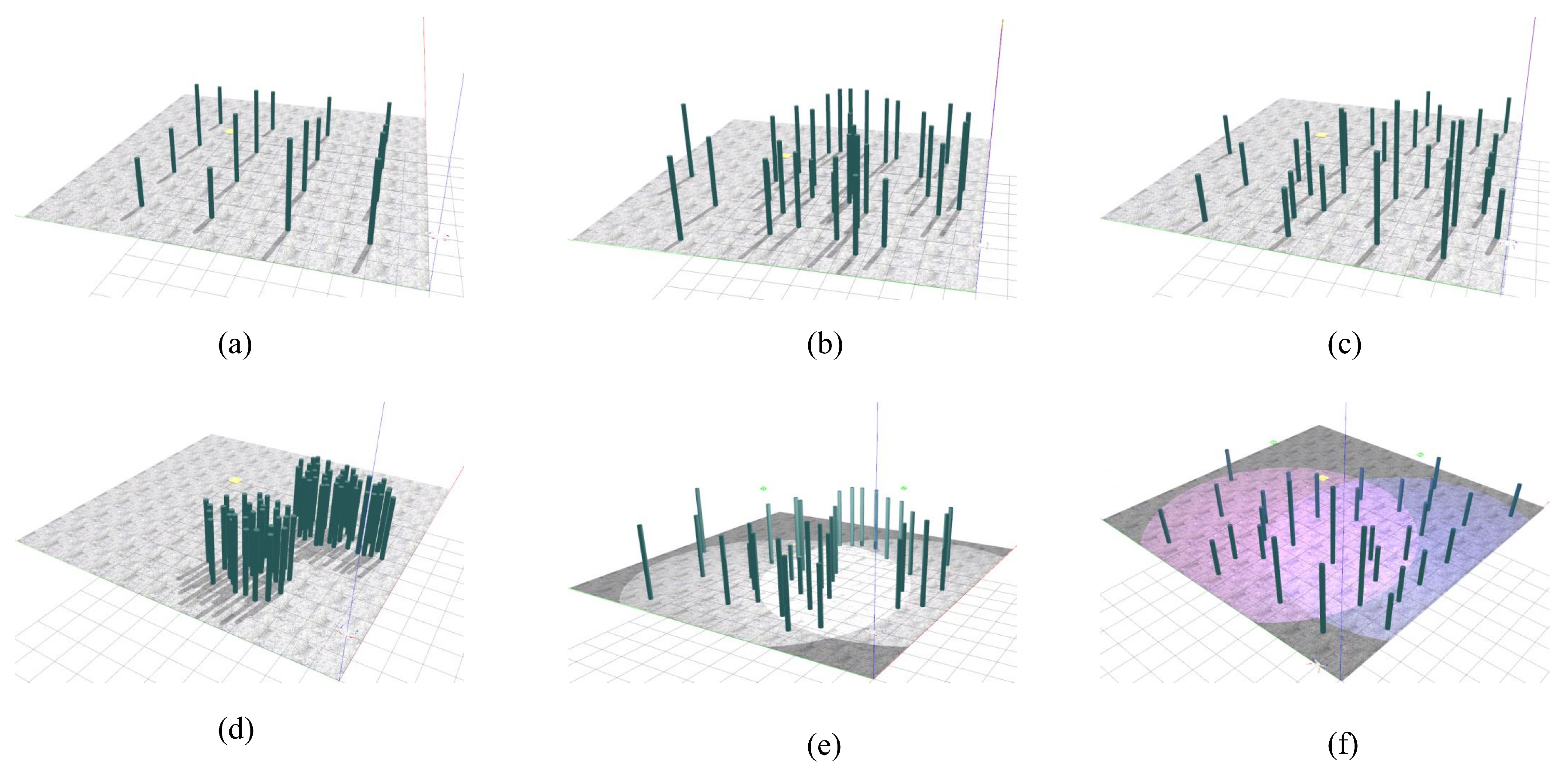
Six distinct virtual environments were used in the simulation experiments conducted in this study to assess the robustness of the proposed navigation algorithm. These environments include one scene with regularly arranged obstacles, two scenes featuring randomly distributed obstacles, and an unknown complex environment with densely packed obstacle piles. Additionally, environments under different lighting conditions were created to assess the adaptability of the algorithm to varying visual conditions. Depth cameras rely on light reflection, and therefore, variations in light color and intensity can interfere with the emitted signal of the camera or alter surface reflectivity, which can impact depth perception. Environments illuminated by different colored light sources were specifically designed to simulate such scenarios. An overview of these simulation environments is illustrated in Figure 8.
The following simulation experiments are all based on the above environment.

4.1.1. Simulation Training Design

The complete workflow of the proposed algorithm is depicted in Algorithm 1. The training process involves the following steps: The agent selects actions based on the existing policy, which enables the agent to engage with the environment, accumulate experiential data, evaluate the advantage function, derive the policy gradient, and subsequently update the parameters associated with the actor and critic models. This cycle is iteratively executed to progressively refine the policy. The Gazebo simulation platform is employed to emulate real-world operating conditions for the UAV to ensure the safety and reliability of agent and environment interactions during training.
Algorithm 1 PPO (Proximal Policy Optimization) optimization algorithm with clipped advantage
1:
Initialize both actor and critic networks with randomly initialized parameters θ 0 and ϕ 0
2:
Create dataset D k to record the set of trajectories τ
3:
for  k = 0 , 1 , 2 , (up to max episodes) do
4:
       Set up environment and drone status while integrating depth images, collect the initial set of observations, and set i = 0
5:
       for  t = 0 , 1 , 2 , (up to max steps per episode) do
6:
              Sample action a t , calculate log π θ k ( a t | s t ) (the log probability under policy π θ k )
7:
              Apply action a t , observe next state s t + 1 , and collect the reward r t
8:
              Record the tuple ( s t , a t , r t , s t + 1 , log π θ k ( a t | s t ) ) into trajectory τ
9:
              if the drone crashes, the goal is reached, or max steps are exceeded then
10:
                  Reinitialize the environment and drone conditions
11:
                  Save the trajectory τ i to D k , increment i by 1
12:
              end if
13:
       end for
14:
       Compute the rewards-to-go R ^ t for each trajectory
15:
       Estimate the advantages A ˜ π t with respect to the current value function V α k based on Equation (1)
16:
       Update actor network using the learning rule in Equation (2)
17:
       Modify critic network weights as per Equation (4)
18:
end for
For this simulation experiment, we select the UAV model in [56], as indicated in Figure 9. This UAV model is a quadcopter model that is commonly used in ROS and Gazebo systems.
Table 2 provides a summary of the essential parameters for the simulated UAV model.
The selected mass and inertia distribution (2.1 kg total, with principal moments 0.0358, 0.0559, and 0.0988 kg·m2) achieves a balance between agility and stability: low inertia about the x- and y-axes permits rapid roll/pitch maneuvers, whereas the higher z-axis inertia helps resist unwanted yaw oscillations. The 0.511 m rotor arms and compact fuselage dimensions (0.472 m width × 0.120 m height) provide sufficient torque leverage without incurring excessive aerodynamic drag. Furthermore, the structural configuration and payload capacity of the UAV enable the integration of onboard sensors such as depth cameras without adversely affecting flight performance or balance.
Table 3 presents the parameters of the depth camera employed in the simulation.
We used a depth sensor with a broad 87°× 58° field of view, covering close obstacles down to 0.2 m and distant features up to 10 m. At 640 × 480 pixels and 30 FPS, the sensor provides sufficient spatial resolution for mid-range obstacle mapping while maintaining the low latency required for real-time collision avoidance. The ±1% distance accuracy underpins reliable depth estimates even in challenging lighting, and the compact 100 × 50 × 30 mm form factor integrates seamlessly into the nose of the UAV.
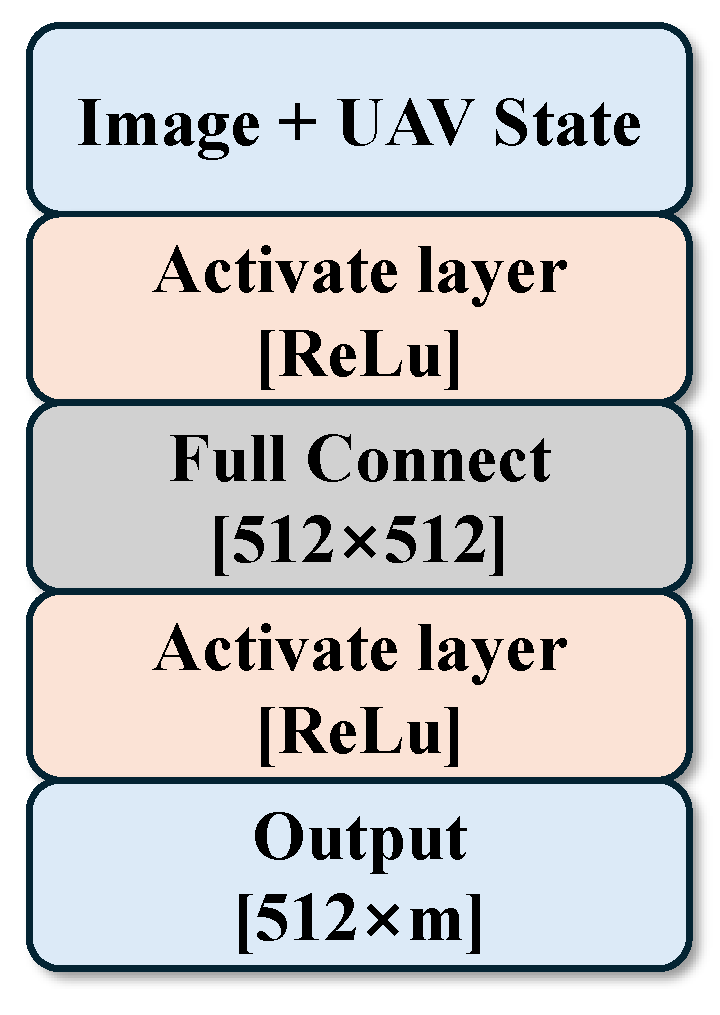
The networks in the proposed PPO algorithm utilize the same structure. As shown in Figure 10, the state information and the depth image features of the UAV are extracted and fused to form the network input. Both networks apply the ReLU ( x ) = max ( 0 , x ) for activation. The actor network delivers a two-dimensional action vector ( m = 2 ), whereas the critic network outputs a singular scalar value ( m = 1 ) representing the calculated state value.

4.1.2. Simulation Training Process

Model training can be conducted using the PPO algorithm once the simulation environment and UAV configuration are established. Table 4 summarizes the hyperparameters employed for training.
During the training process, the configuration of these hyperparameters directly affects training efficiency and training success rate. The update interval is set to 2 × 10 2 s, which can control the frequency of model updates. The total number of steps is 2 × 10 8 , which is selected based on the world size to ensure sufficient training time. The sizes of the state and action spaces are determined based on task requirements. A reward discount factor of 0.99 is used to emphasize long-term rewards. The learning rate ( 3 × 10 4 ) governs the speed of weight adjustments, whereas the clipping threshold ( ϵ ) is set to 0.25 for preventing excessive policy changes and maintaining training stability. These hyperparameters can be optimized to improve the effectiveness of the PPO algorithm in unknown complex environments and train the control policy more effectively.
The simulation experiment was conducted on a computer with an Ubuntu 18.04 operating system with the following specifications: CPU: Intel 12900K, GPU: Nvidia 3090, RAM: 16 GB, and Storage: 128 GB hard disk. Figure 11 presents the total reward per episode during training, along with the average reward over 25 episodes in the aforementioned environments. A higher y-axis value indicates better training performance, reflecting a higher total reward achieved by the agent. Additional rewards are obtained after successfully avoiding obstacles, and therefore, the maximum reward, i.e., the highest value on the y-axis, varies across different environments. However, Figure 11 shows that the cumulative rewards of the proposed algorithm gradually increase and eventually converge across all environments. Furthermore, during training, we employed a curriculum learning approach. The UAV was initially tasked with navigating a simpler world with fewer obstacles, which enabled it to gradually acquire basic navigation skills. The UAV transitioned to more complex environments when the success rate reached an acceptable threshold. This approach facilitated more stable learning by reducing the complexity of the task at the outset and enhanced the ability of the agent to generalize to more challenging scenarios. Curriculum learning can accelerate convergence, improve performance, and decrease the chances of being trapped in the local optima, particularly in environments with high complexity.
The effectiveness of our algorithm is also illustrated in Figure 11. The UAV is initially trained in a relatively simple environment, after which it quickly masters the navigation task, resulting in a continuous increase in reward. Once a certain performance threshold is reached, the environment transitions to more complex scenarios, such as the various worlds shown in Figure 8, and the UAV then learns the obstacle avoidance task. This approach enables the network to quickly learn the complete task and obtain a high reward magnitude over a brief period. The maximum reward values differ across environments because of varying obstacle distributions. In our experiments, the agent learned an effective policy for obstacle avoidance and navigation in most environments after approximately 1750 training iterations. Across all designed simulated environments, the learning process successfully converged to feasible policies, and no training failures were observed.
In environments with more structured obstacle layouts, the growth of the reward shows a linear trend, as observed in environment (a). Since the UAV has learned basic navigation, the reward is mainly affected by the number of obstacles on the path, as shown in environments (c) and (d). In environment (d), obstacles are concentrated in a single area, the UAV quickly learns the best navigation path during training, and the reward converges after a few rounds of training. It is important to note that due to the exploratory nature of the algorithm, the reward may occasionally drop during the training cycle as the algorithm refines its pathfinding approach. This is particularly evident in environments with varying lighting conditions, such as worlds (e) and (f), where the algorithm successfully completes navigation and obstacle avoidance tasks despite differences in lighting conditions.
Overall, the algorithm exhibits strong adaptability and robustness, and it can efficiently find appropriate strategies in environments with varying obstacle distributions and lighting conditions.

4.1.3. Simulation Training Result

During the policy training phase, the algorithm must explore to some extent, with actions sampled from a probability distribution. Consequently, the actions output during training are not necessarily optimal. In the policy testing phase, we simplified the neural network architecture (Figure 12), retaining only the policy network responsible for directly selecting the optimal action and eliminating parts such as the critic network, loss function, and experience replay buffer. This simplifies the balance between exploration and exploitation during training, allowing the focus to shift to evaluating the performance and correctness of the control strategy. The test environment remains the same as that during training, and it is conducted in the Gazebo simulation, with input comprising a combination of UAV status and depth image data.
In addition, through system experiments, the traditional method and the proposed scheme are compared in terms of response delay, computational complexity, and other indicators. The results are shown in Table 5.
As shown in Table 5, the proposed method outperforms traditional approaches in terms of system response latency. Compared with conventional map-based path planning and position control algorithms, our end-to-end scheme reduces latency by up to 78.46%. This performance gain can be attributed to the elimination of the modular separation between perception, planning, and control, which typically introduces inter-module communication and synchronization overhead. By directly mapping onboard sensory data to control commands, our approach effectively alleviates the response delay and lowers computational complexity.
Then, we also compared and analyzed it with several other DRL and SLAM-based methods in terms of success rate, task completion time, as shown in Table 6.
Table 6 shows that the proposed method achieves the highest success rate with the shortest task time.
In order to quantitatively evaluate the energy consumption during mission execution, we refer to the energy consumption approximation method in the literature [62] and use the square integral of the acceleration corresponding to the discrete speed change as a proxy indicator of energy consumption, and obtain Equation (7).
E = t = 1 T v t v t 1 Δ t 2 Δ t
where E is the energy approximation comparison value; T is the total number of time steps in the mission; v t and v t 1 are the UAV velocity vectors at time steps t and t 1 , respectively; Δ t is the time interval between consecutive velocity samples.
Based on the environment in World (c) of Figure 8, we remove the energy-related component from the reward function and perform a comparative analysis, as shown in Table 7.
Table 7 compares the UAV’s performance with and without the energy-related reward component. When this component is included, energy consumption is reduced by 9%. This constraint is expected to be even more effective in larger and more complex environments, where frequent acceleration and deceleration are more common. Encouraging smoother motion helps mitigate energy spikes and enhances overall flight stability.
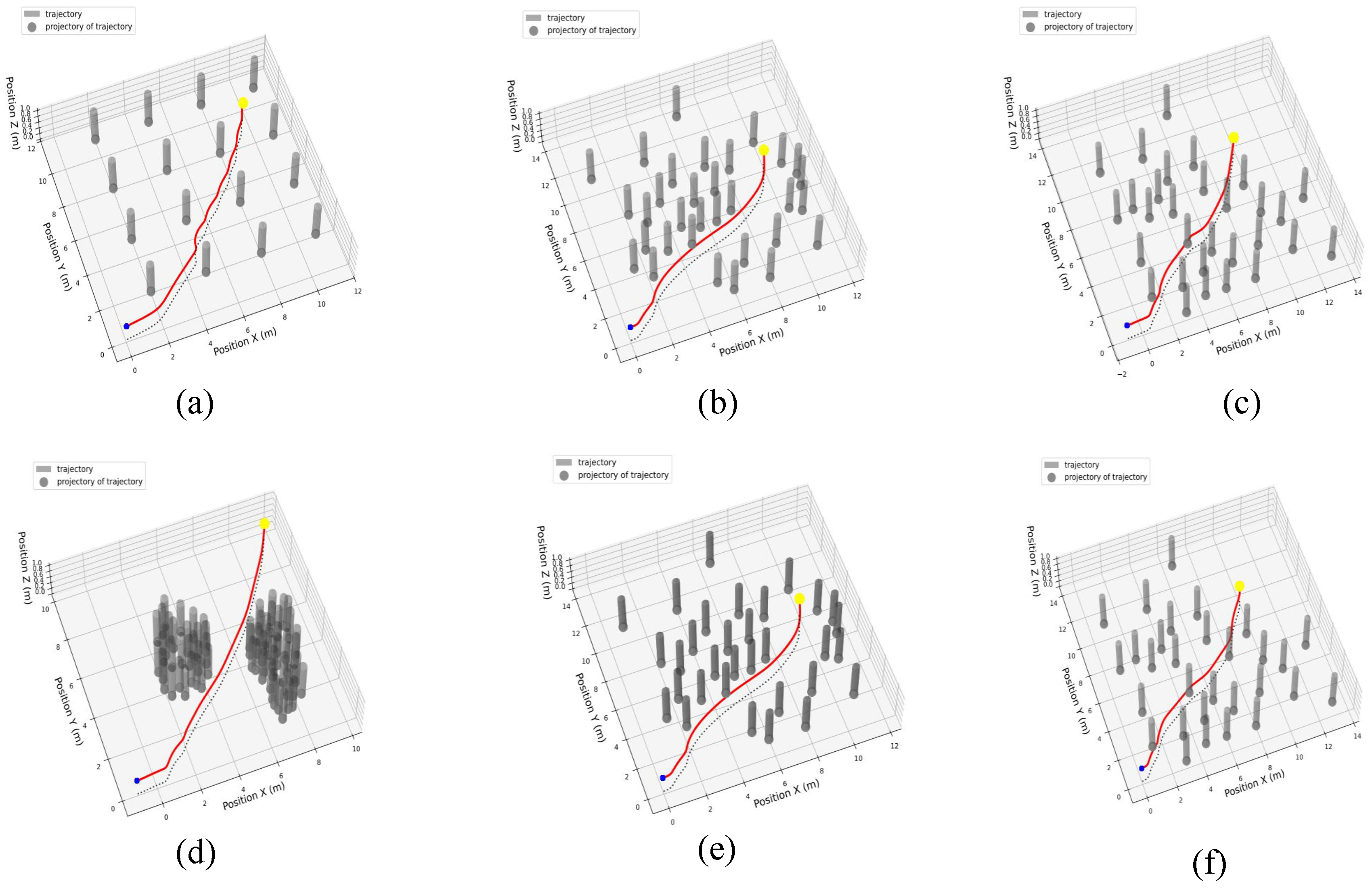
Figure 13 presents the test results, which depict the flight trajectory of the UAV and the corresponding projection on the X-Y plane. The algorithm presented in this study successfully accomplishes the task with accuracy across various environments.
As shown in Figure 13, the red solid line represents the flight trajectory of the UAV, whereas the gray dashed line shows its projection onto the XY plane, excluding the z-axis component. The trained network can complete the task under distributions with different lighting conditions and different obstacles. Furthermore, the algorithm can more easily learn a path that can perfectly avoid obstacles and is as close to a straight line as possible because of the introduction of curriculum learning. In an environment with dense obstacles, such as World (d), the algorithm chooses a tangent direction to bypass the obstacle pile, maximizing efficiency. This proves that our algorithm can effectively learn navigation and obstacle avoidance strategies.

4.2. Real-World Experiment

We conducted a real-world experiment to verify the algorithm. The overall experimental architecture is shown in Figure 14.
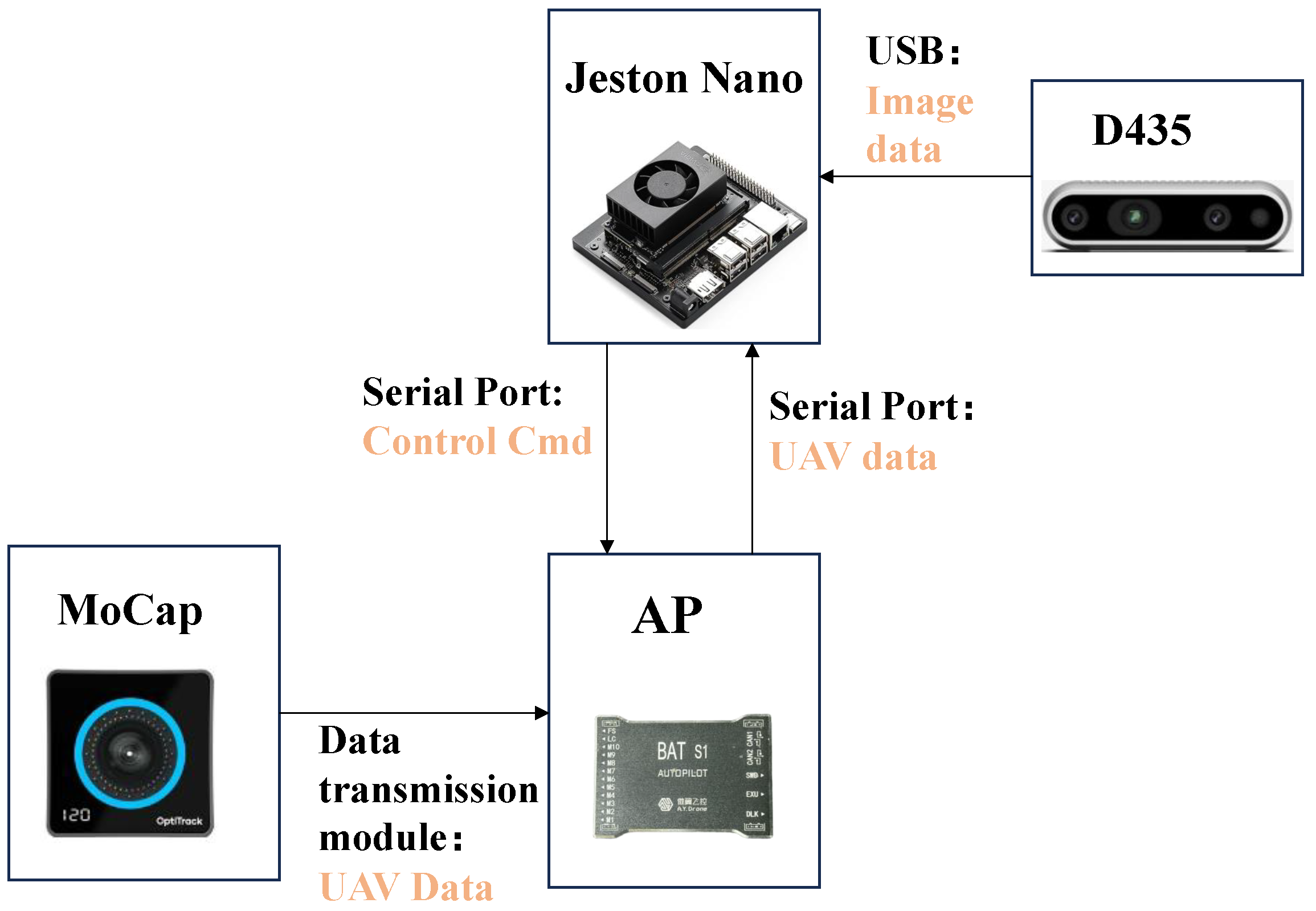
The general process follows a structure similar to that shown in Figure 12. The key difference is that the environment and UAV are real instead of being simulated in Gazebo. The operation of the high-level controller relies on the Jetson Nano. The data from the drone is captured via the MotionCapture device, transmitted to the lower-level flight controller via the data transmission module, and sent to the upper-level controller (Jetson Nano) through the serial port. Visual data are acquired using a D435 depth camera, which communicates with the host controller over USB. The host controller processes the lower-level control instructions and sends commands to the flight controller through the serial port. Figure 15 presents the schematic of the UAV used in the actual flight experiment presented in this paper.
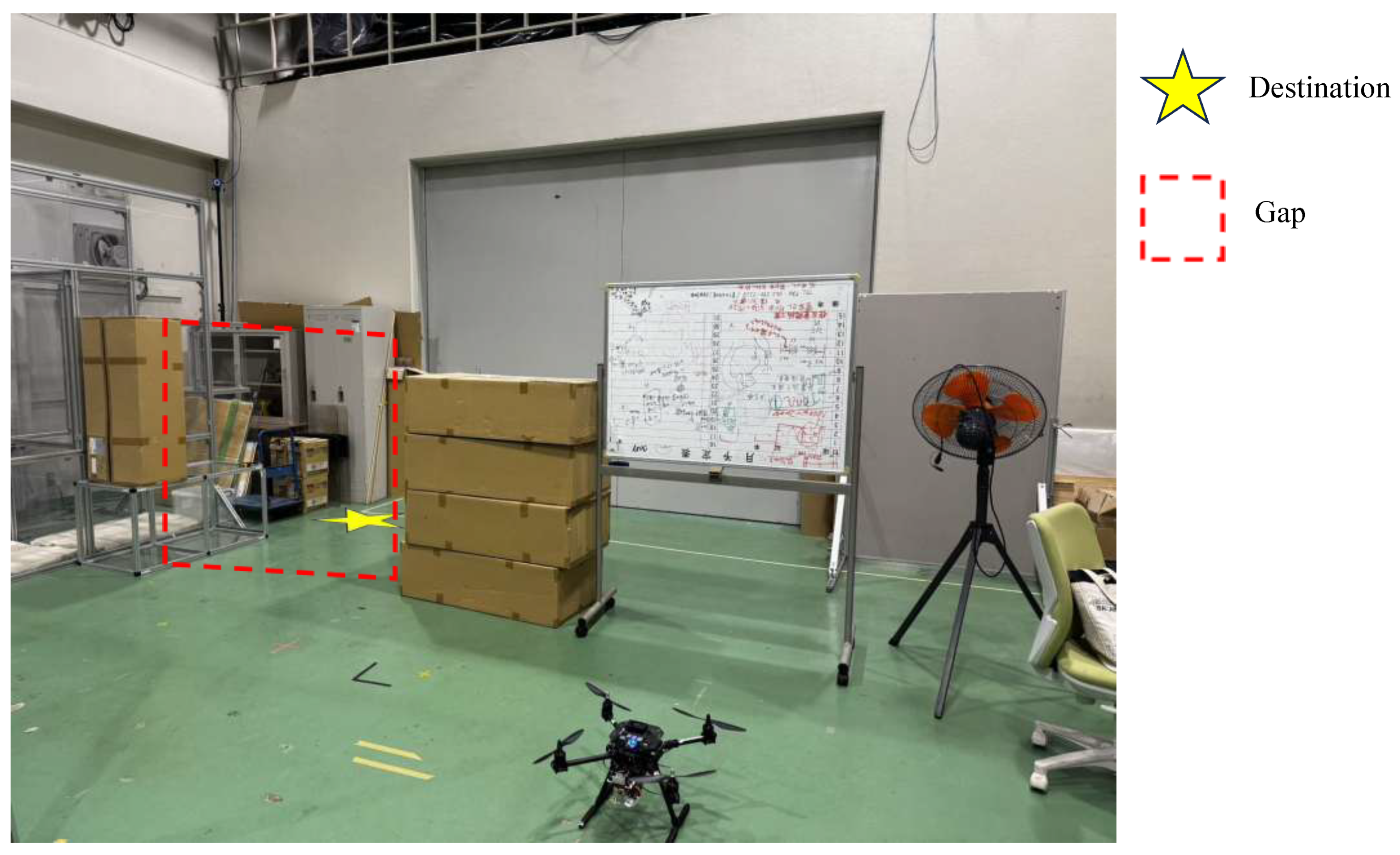
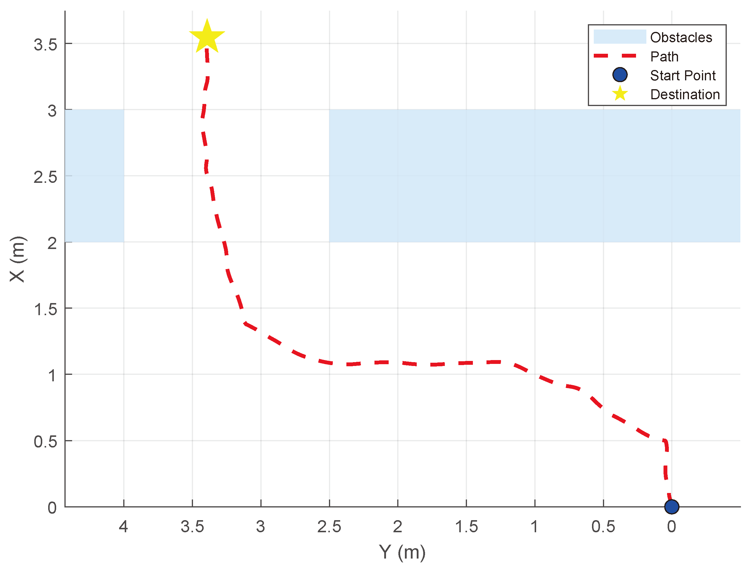
The design of the real-world task is shown in Figure 16. We created a real environment where a UAV must pass through a doorway situated between two walls. In this task, the UAV is required to take off from one side of the wall, pass through the gap to the other side, and then hover. The red dotted line represents the passable doorway, whereas the yellow five-pointed star marks the destination.
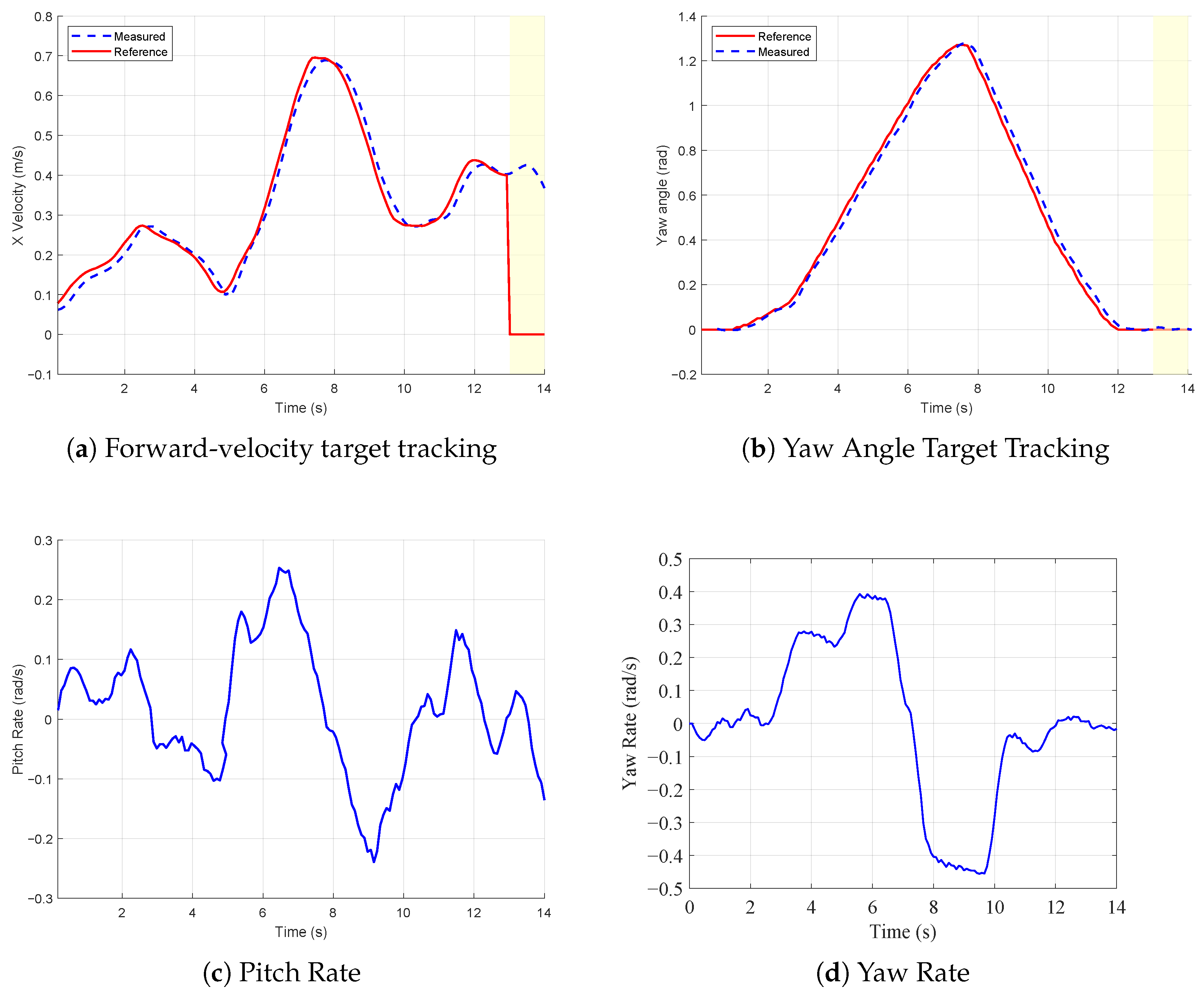
In this experiment, the Jeston Nano outputs the forward speed target value and heading angle target value required for UAV control. The control scenarios are illustrated in Figure 17. Figure 17a shows the tracking performance of the forward velocity. Figure 17b shows the tracking of the target yaw angle, where the red solid line indicates the desired yaw angle, and the blue dashed line represents the measured yaw angle of the UAV. The light yellow shaded region in both plots marks the moment when the UAV reaches the target point and exits the autonomous control mode. Figure 17c,d show the angular rate data of pitch and yaw, respectively.
During the flight, the reinforcement learning algorithm continuously provides the UAV with guidance on direction and forward velocity, which enables it to avoid obstacles and reach the target. Given the relatively confined experimental environment and non-negligible size of the UAV, the maximum flight speed is limited to 0.7 m/s to ensure safe operation. This speed does not represent the upper performance limit of our method, and instead, it represents a safety constraint specific to the experimental setup.
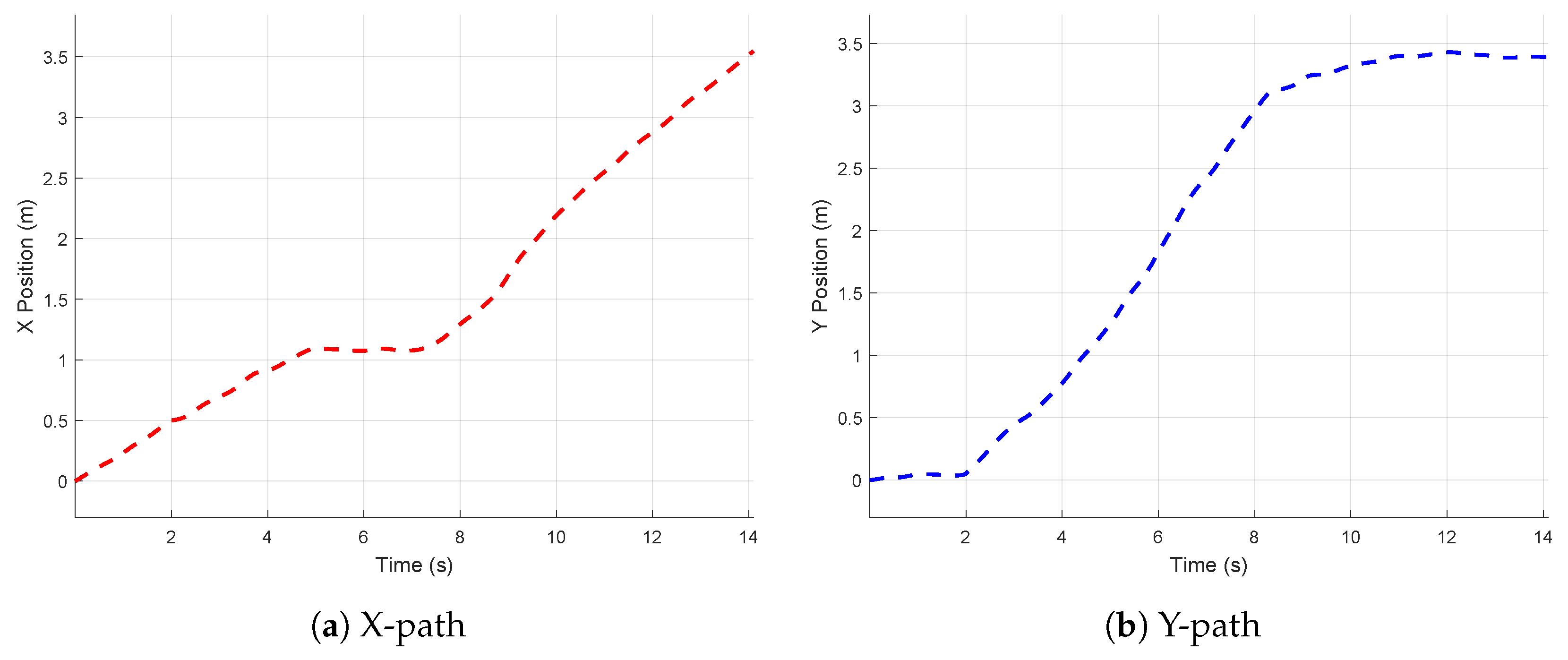
The UAV completes the navigation and obstacle avoidance tasks based on the control instructions. Figure 18 shows the graph of X and Y over time during the obstacle avoidance navigation process of the drone, and Figure 19 shows the overall motion trajectory of the drone. As shown in Figure 19, the drone successfully reaches the target point while avoiding obstacles, validating the effectiveness of the proposed strategy for completing the task.

5. Conclusions

This paper proposes an end-to-end navigation and control algorithm based on reinforcement learning driven by UAV vision in an unknown complex environment with unknown obstacles. Unlike conventional navigation algorithms, the proposed algorithm inherits path planning and position control; directly considers the state, visual information, and mission objectives of the UAV as network inputs; directly outputs the yaw angular and forward-velocity target values; and controls the UAV through the underlying controller. We constructed a multi-faceted reward function that considers the completion of the navigation task and comprehensively considers energy consumption and obstacle avoidance capabilities to effectively optimize the policy network. Moreover, we used the Gazebo software to build a virtual environment and physicalize the UAV to ensure that the results in the simulation can be deployed in the real world. Then, we combined it with the same underlying controller to achieve stable speed command tracking.
We built different worlds in Gazebo, including obstacles with different distributions, environments under different light sources, etc., to evaluate the reliability and feasibility of the proposed algorithm. The results indicated that our control strategy completed navigation tasks in various unknown environments. Furthermore, we tested it in the real world, once again confirming the feasibility of this algorithm.
The comprehensive results indicate that our proposed method excels in static unknown complex environments. However, some problems remain: First, the training of our strategy takes a long time (approximately 8 h per training) because of the existence of visual convolution. In the future, we plan to increase training efficiency by implementing parallel or curriculum learning. Second, our algorithm has not been tested for moving obstacle targets. In this case, the algorithm must be able to adjust the motion trajectory in advance while considering dynamic obstacles. We plan to research navigation algorithms in unknown dynamic environments in the future. Solving these problems can help further improve the universality of navigation strategies. Moreover, due to discrepancies between the simulation environment and the real world—such as differences in UAV actuation responses and sensor noise—the actual flight performance may deviate from simulation results. To address this gap, we plan to incorporate a Sim-to-Real (Sim2Real) transfer strategy in future work to enhance the robustness of our method. Regarding collisions and entrapment issues, we aim to further refine the reward function by introducing risk-level grading based on the UAV’s proximity to obstacles. Under different risk levels, the UAV will prioritize different tasks, for example, focusing more on obstacle avoidance when a collision is imminent.

Author Contributions

Conceptualization, H.W. and W.W.; methodology, H.W.; software, T.W.; validation, H.W. and T.W.; formal analysis, H.W.; investigation, H.W.; resources, H.W.; writing—original draft preparation, H.W.; writing—review and editing, S.S. and W.W. All authors have read and agreed to the published version of the manuscript.

Funding

This paper is based on results obtained from a project, JPNP22002, commissioned by the New Energy and Industrial Technology Development Organization (NEDO).

Data Availability Statement

Data is contained within the article.

Conflicts of Interest

The authors declare no conflicts of interest.

References

  1. Rezwan, S.; Choi, W. Artificial intelligence approaches for UAV navigation: Recent advances and future challenges. IEEE Access 2022, 10, 26320–26339. [Google Scholar] [CrossRef]
  2. Mohsan, S.A.H.; Othman, N.Q.H.; Li, Y.; Alsharif, M.H.; Khan, M.A. Unmanned aerial vehicles (UAVs): Practical aspects, applications, open challenges, security issues, and future trends. Intell. Serv. Robot. 2023, 16, 109–137. [Google Scholar] [CrossRef]
  3. Wang, G.; Chen, Y.; An, P.; Hong, H.; Hu, J.; Huang, T. UAV-YOLOv8: A small-object-detection model based on improved YOLOv8 for UAV aerial photography scenarios. Sensors 2023, 23, 7190. [Google Scholar] [CrossRef]
  4. Liu, W.; Zhang, T.; Huang, S.; Li, K. A hybrid optimization framework for UAV reconnaissance mission planning. Comput. Ind. Eng. 2022, 173, 108653. [Google Scholar] [CrossRef]
  5. Lyu, M.; Zhao, Y.; Huang, C.; Huang, H. Unmanned aerial vehicles for search and rescue: A survey. Remote Sens. 2023, 15, 3266. [Google Scholar] [CrossRef]
  6. Srivastava, A.; Prakash, J. Techniques, answers, and real-world UAV implementations for precision farming. Wirel. Pers. Commun. 2023, 131, 2715–2746. [Google Scholar] [CrossRef]
  7. Ghambari, S.; Golabi, M.; Jourdan, L.; Lepagnot, J.; Idoumghar, L. UAV path planning techniques: A survey. RAIRO-Oper. Res. 2024, 58, 2951–2989. [Google Scholar] [CrossRef]
  8. Wooden, D.; Malchano, M.; Blankespoor, K.; Howardy, A.; Rizzi, A.A.; Raibert, M. Autonomous navigation for BigDog. In Proceedings of the 2010 IEEE International Conference on Robotics and Automation, Anchorage, AK, USA, 3–7 May 2010; pp. 4736–4741. [Google Scholar]
  9. Hening, S.; Ippolito, C.A.; Krishnakumar, K.S.; Stepanyan, V.; Teodorescu, M. 3D LiDAR SLAM integration with GPS/INS for UAVs in urban GPS-degraded environments. In Proceedings of the AIAA Information Systems-AIAA Infotech@ Aerospace, Kissimmee, FL, USA, 8–12 January 2017; p. 0448. [Google Scholar]
  10. Kumar, G.A.; Patil, A.K.; Patil, R.; Park, S.S.; Chai, Y.H. A LiDAR and IMU integrated indoor navigation system for UAVs and its application in real-time pipeline classification. Sensors 2017, 17, 1268. [Google Scholar] [CrossRef]
  11. Qin, H.; Meng, Z.; Meng, W.; Chen, X.; Sun, H.; Lin, F.; Ang, M.H. Autonomous exploration and mapping system using heterogeneous UAVs and UGVs in GPS-denied environments. IEEE Trans. Veh. Technol. 2019, 68, 1339–1350. [Google Scholar] [CrossRef]
  12. Gomez-Ojeda, R.; Moreno, F.A.; Zuniga-Noël, D.; Scaramuzza, D.; Gonzalez-Jimenez, J. PL-SLAM: A stereo SLAM system through the combination of points and line segments. IEEE Trans. Robot. 2019, 35, 734–746. [Google Scholar] [CrossRef]
  13. Zhou, H.; Zou, D.; Pei, L.; Ying, R.; Liu, P.; Yu, W. StructSLAM: Visual SLAM with building structure lines. IEEE Trans. Veh. Technol. 2015, 64, 1364–1375. [Google Scholar] [CrossRef]
  14. Low, D.G. Distinctive image features from scale-invariant keypoints. J. Comput. Vis. 2004, 60, 91–110. [Google Scholar] [CrossRef]
  15. Cho, G.; Kim, J.; Oh, H. Vision-based obstacle avoidance strategies for MAVs using optical flows in 3-D textured environments. Sensors 2019, 19, 2523. [Google Scholar] [CrossRef] [PubMed]
  16. Aguilar, W.G.; Álvarez, L.; Grijalva, S.; Rojas, I. Monocular vision-based dynamic moving obstacles detection and avoidance. In Proceedings of the Intelligent Robotics and Applications: 12th International Conference, ICIRA 2019, Shenyang, China, 8–11 August 2019; Proceedings, Part V 12. pp. 386–398. [Google Scholar]
  17. Mahjri, I.; Dhraief, A.; Belghith, A.; AlMogren, A.S. SLIDE: A straight line conflict detection and alerting algorithm for multiple unmanned aerial vehicles. IEEE Trans. Mob. Comput. 2017, 17, 1190–1203. [Google Scholar] [CrossRef]
  18. Miller, A.; Miller, B. Stochastic control of light UAV at landing with the aid of bearing-only observations. In Proceedings of the Eighth International Conference on Machine Vision (ICMV 2015), Barcelona, Spain, 19–21 November 2015; Volume 9875, pp. 474–483. [Google Scholar]
  19. Expert, F.; Ruffier, F. Flying over uneven moving terrain based on optic-flow cues without any need for reference frames or accelerometers. Bioinspiration Biomimetics 2015, 10, 026003. [Google Scholar] [CrossRef]
  20. Goh, S.T.; Abdelkhalik, O.; Zekavat, S.A.R. A weighted measurement fusion Kalman filter implementation for UAV navigation. Aerosp. Sci. Technol. 2013, 28, 315–323. [Google Scholar] [CrossRef]
  21. Mnih, V. Playing atari with deep reinforcement learning. arXiv 2013. [Google Scholar] [CrossRef]
  22. Silver, D.; Schrittwieser, J.; Simonyan, K.; Antonoglou, I.; Huang, A.; Guez, A.; Hubert, T.; Baker, L.; Lai, M.; Bolton, A.; et al. Mastering the game of go without human knowledge. Nature 2017, 550, 354–359. [Google Scholar] [CrossRef]
  23. Sallab, A.E.; Abdou, M.; Perot, E.; Yogamani, S. Deep reinforcement learning framework for autonomous driving. arXiv 2017, arXiv:1704.02532. [Google Scholar] [CrossRef]
  24. Faust, A.; Oslund, K.; Ramirez, O.; Francis, A.; Tapia, L.; Fiser, M.; Davidson, J. Prm-rl: Long-range robotic navigation tasks by combining reinforcement learning and sampling-based planning. In Proceedings of the 2018 IEEE International Conference on Robotics and Automation (ICRA), Brisbane, QLD, Australia, 21–25 May 2018; pp. 5113–5120. [Google Scholar]
  25. Pham, H.X.; La, H.M.; Feil-Seifer, D.; Nguyen, L.V. Autonomous uav navigation using reinforcement learning. arXiv 2018. [Google Scholar] [CrossRef]
  26. Loquercio, A.; Maqueda, A.I.; Del-Blanco, C.R.; Scaramuzza, D. Dronet: Learning to fly by driving. IEEE Robot. Autom. Lett. 2018, 3, 1088–1095. [Google Scholar] [CrossRef]
  27. Lu, Y.; Xue, Z.; Xia, G.S.; Zhang, L. A survey on vision-based UAV navigation. Geo-Spat. Inf. Sci. 2018, 21, 21–32. [Google Scholar] [CrossRef]
  28. Chen, T.; Gupta, S.; Gupta, A. Learning exploration policies for navigation. arXiv 2019. [Google Scholar] [CrossRef]
  29. Polvara, R.; Patacchiola, M.; Sharma, S.; Wan, J.; Manning, A.; Sutton, R.; Cangelosi, A. Autonomous quadrotor landing using deep reinforcement learning. arXiv 2017, arXiv:1709.03339. [Google Scholar]
  30. Kalidas, A.P.; Joshua, C.J.; Md, A.Q.; Basheer, S.; Mohan, S.; Sakri, S. Deep reinforcement learning for vision-based navigation of UAVs in avoiding stationary and mobile obstacles. Drones 2023, 7, 245. [Google Scholar] [CrossRef]
  31. AlMahamid, F.; Grolinger, K. VizNav: A Modular Off-Policy Deep Reinforcement Learning Framework for Vision-Based Autonomous UAV Navigation in 3D Dynamic Environments. Drones 2024, 8, 173. [Google Scholar] [CrossRef]
  32. Xu, G.; Jiang, W.; Wang, Z.; Wang, Y. Autonomous obstacle avoidance and target tracking of UAV based on deep reinforcement learning. J. Intell. Robot. Syst. 2022, 104, 60. [Google Scholar] [CrossRef]
  33. Yang, J.; Lu, S.; Han, M.; Li, Y.; Ma, Y.; Lin, Z.; Li, H. Mapless navigation for UAVs via reinforcement learning from demonstrations. Sci. China Technol. Sci. 2023, 66, 1263–1270. [Google Scholar] [CrossRef]
  34. Zhao, H.; Fu, H.; Yang, F.; Qu, C.; Zhou, Y. Data-driven offline reinforcement learning approach for quadrotor’s motion and path planning. Chin. J. Aeronaut. 2024, 37, 386–397. [Google Scholar] [CrossRef]
  35. Sun, T.; Gu, J.; Mou, J. UAV autonomous obstacle avoidance via causal reinforcement learning. Displays 2025, 87, 102966. [Google Scholar] [CrossRef]
  36. Sonny, A.; Yeduri, S.R.; Cenkeramaddi, L.R. Q-learning-based unmanned aerial vehicle path planning with dynamic obstacle avoidance. Appl. Soft Comput. 2023, 147, 110773. [Google Scholar] [CrossRef]
  37. Wang, J.; Yu, Z.; Zhou, D.; Shi, J.; Deng, R. Vision-Based Deep Reinforcement Learning of UAV Autonomous Navigation Using Privileged Information. arXiv 2024. [Google Scholar] [CrossRef]
  38. Samma, H.; El-Ferik, S. Autonomous UAV Visual Navigation Using an Improved Deep Reinforcement Learning. IEEE Access 2024, 12, 79967–79977. [Google Scholar] [CrossRef]
  39. Shao, X.; Zhang, F.; Liu, J.; Zhang, Q. Finite-Time Learning-Based Optimal Elliptical Encircling Control for UAVs With Prescribed Constraints. IEEE Trans. Intell. Transp. Syst. 2025, 26, 7065–7080. [Google Scholar] [CrossRef]
  40. Li, X.; Cheng, Y.; Shao, X.; Liu, J.; Zhang, Q. Safety-Certified Optimal Formation Control for Nonline-ar Multi-Agents via High-Order Control Barrier Function. IEEE Internet Things J. 2025, 12, 24586–24598. [Google Scholar] [CrossRef]
  41. Lopez-Sanchez, I.; Moreno-Valenzuela, J. PID control of quadrotor UAVs: A survey. Annu. Rev. Control 2023, 56, 100900. [Google Scholar] [CrossRef]
  42. Wang, Q.; Wang, W.; Suzuki, S.; Namiki, A.; Liu, H.; Li, Z. Design and implementation of UAV velocity controller based on reference model sliding mode control. Drones 2023, 7, 130. [Google Scholar] [CrossRef]
  43. Wang, Q.; Wang, W.; Suzuki, S. UAV trajectory tracking under wind disturbance based on novel antidisturbance sliding mode control. Aerosp. Sci. Technol. 2024, 149, 109138. [Google Scholar] [CrossRef]
  44. Zeghlache, S.; Rahali, H.; Djerioui, A.; Benyettou, L.; Benkhoris, M.F. Robust adaptive backstepping neural networks fault tolerant control for mobile manipulator UAV with multiple uncertainties. Math. Comput. Simul. 2024, 218, 556–585. [Google Scholar] [CrossRef]
  45. Ramezani, M.; Habibi, H.; Sanchez-Lopez, J.L.; Voos, H. UAV path planning employing MPC-reinforcement learning method considering collision avoidance. In Proceedings of the 2023 International Conference on Unmanned Aircraft Systems (ICUAS), Warsaw, Poland, 6–9 June 2023; pp. 507–514. [Google Scholar]
  46. Li, S.; Shao, X.; Wang, H.; Liu, J.; Zhang, Q. Adaptive Critic Attitude Learning Control for Hypersonic Morphing Vehicles without Backstepping. IEEE Trans. Aerosp. Electron. Syst. 2025, 61, 8787–8803. [Google Scholar] [CrossRef]
  47. Zhang, Q.; Dong, J. Disturbance-observer-based adaptive fuzzy control for nonlinear state constrained systems with input saturation and input delay. Fuzzy Sets Syst. 2020, 392, 77–92. [Google Scholar] [CrossRef]
  48. Tian, Y.; Chang, Y.; Arias, F.H.; Nieto-Granda, C.; How, J.P.; Carlone, L. Kimera-multi: Robust, distributed, dense metric-semantic slam for multi-robot systems. IEEE Trans. Robot. 2022, 38, 2022–2038. [Google Scholar] [CrossRef]
  49. Yang, M.; Yao, M.R.; Cao, K. Overview on issues and solutions of SLAM for mobile robot. Comput. Syst. Appl. 2018, 27, 1–10. [Google Scholar] [CrossRef]
  50. Mao, Y.; Yu, X.; Zhang, Z.; Wang, K.; Wang, Y.; Xiong, R.; Liao, Y. Ngel-slam: Neural implicit representation-based global consistent low-latency slam system. In Proceedings of the 2024 IEEE International Conference on Robotics and Automation (ICRA), Yokohama, Japan, 13–17 May 2024; Volume 2024, pp. 6952–6958. [Google Scholar]
  51. Pendleton, S.D.; Andersen, H.; Du, X.; Shen, X.; Meghjani, M.; Eng, Y.H.; Rus, D.; Ang, M.H. Perception, planning, control, and coordination for autonomous vehicles. Machines 2017, 5, 6. [Google Scholar] [CrossRef]
  52. Airlangga, G.; Sukwadi, R.; Basuki, W.W.; Sugianto, L.F.; Nugroho, O.I.A.; Kristian, Y.; Rahmananta, R. Adaptive Path Planning for Multi-UAV Systems in Dynamic 3D Environments: A Multi-Objective Framework. Designs 2024, 8, 136. [Google Scholar] [CrossRef]
  53. Airlangga, G.; Sukwadi, R.; Basuki, W.W.; Sugianto, L.F.; Nugroho, O.I.A.; Kristian, Y.; Rahmananta, R. Multi-objective path planning of an autonomous mobile robot using hybrid PSO-MFB optimization algorithm. Appl. Soft Comput. 2020, 89, 106076. [Google Scholar]
  54. Wu, H. Model-Free UAV Navigation in Unknown Complex Environments Using Vision-Based Reinforcement Learning. Figshare, 6 May 2025. Video, 37 Seconds. Available online: https://figshare.com/articles/media/Model-Free_UAV_Navigation_in_Unknown_Complex_Environments_Using_Vision-Based_Reinforcement_Learning/28934846/1?file=54234020 (accessed on 26 July 2025).
  55. Wu, H. Model-Free UAV Navigation in Unknown Complex Environments Using Vision-Based Reinforcement Learning. 26 July 2025. Available online: https://github.com/ORI-coderH/Vision-Based-RL-Navigation.git (accessed on 26 July 2025).
  56. Furrer, F.; Burri, M.; Achtelik, M.; Siegwart, R. Robot Operating System (Ros): The Complete Reference (Volume 1); Springer International Publishing: Cham, Switzerland, 2016; Volume 1, pp. 595–625. [Google Scholar]
  57. López, E.; García, S.; Barea, R.; Bergasa, L.M.; Molinos, E.J.; Arroyo, R.; Romera, E.; Pardo, S. A Multi-Sensorial Simultaneous Localization and Mapping (SLAM) System for Low-Cost Micro Aerial Vehicles in GPS-Denied Environments. Sensors 2017, 17, 802. [Google Scholar] [CrossRef]
  58. Norbelt, M.; Luo, X.; Sun, J.; Claude, U. UAV Localization in Urban Area Mobility Environment Based on Monocular VSLAM with Deep Learning. Drones 2025, 9, 171. [Google Scholar] [CrossRef]
  59. Elamin, A.; El-Rabbany, A.; Jacob, S. Event-Based Visual/Inertial Odometry for UAV Indoor Navigation. Sensors 2025, 25, 61. [Google Scholar] [CrossRef]
  60. Wang, J.; Yu, Z.; Zhou, D.; Shi, J.; Deng, R. Vision-Based Deep Reinforcement Learning of Unmanned Aerial Vehicle (UAV) Autonomous Navigation Using Privileged Information. Drones 2024, 8, 782. [Google Scholar] [CrossRef]
  61. Tezerjani, M.D.; Khoshnazar, M.; Tangestanizadeh, M.; Kiani, A.; Yang, Q. A survey on reinforcement learning applications in slam. arXiv 2024. [Google Scholar] [CrossRef]
  62. Kolagar, S.A.A.; Shahna, M.H.; Mattila, J. Combining Deep Reinforcement Learning with a Jerk-Bounded Trajectory Generator for Kinematically Constrained Motion Planning. arXiv 2024. [CrossRef]
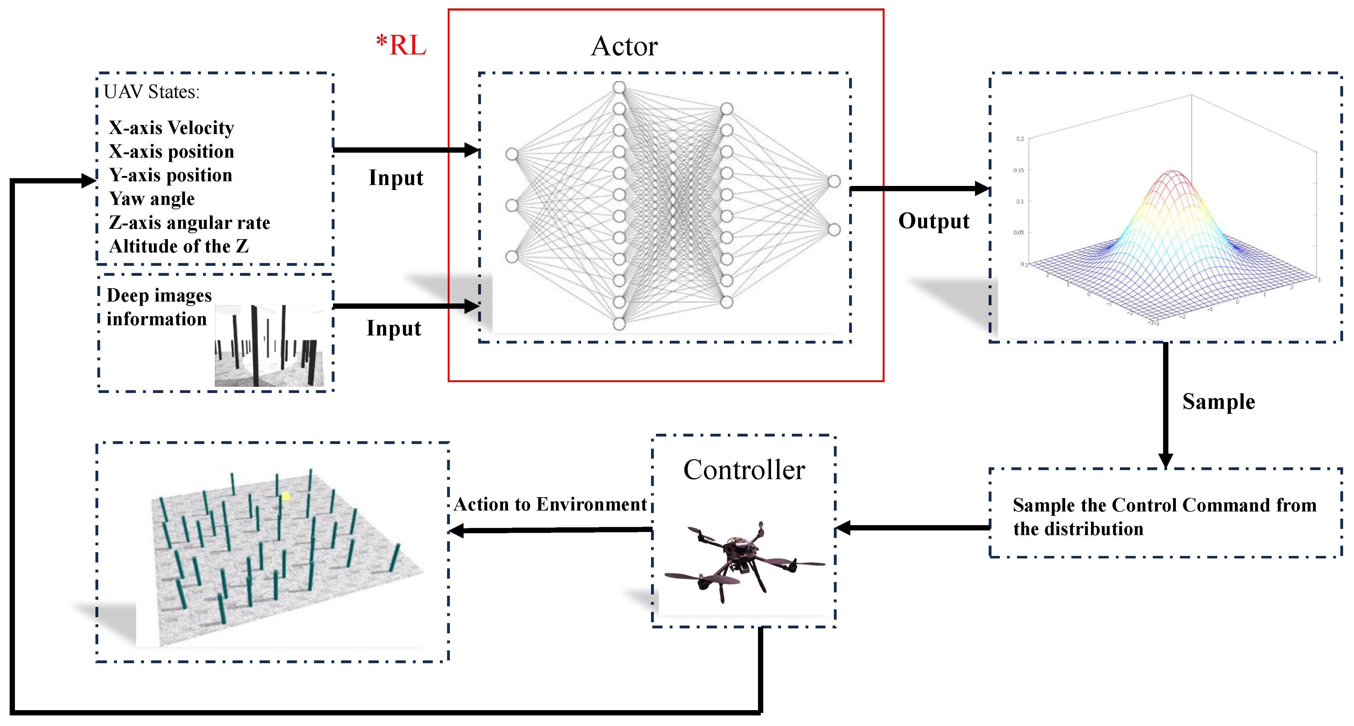
Figure 1. Overall RL-based system architecture and design.
Drones 09 00566 g001
Figure 2. UAV flight control architecture.
Drones 09 00566 g002
Figure 3. UAV controller architecture.
Drones 09 00566 g003
Figure 4. PPO-based navigation policy architecture.
Drones 09 00566 g004
Figure 5. State space design for UAV navigation.
Drones 09 00566 g005
Figure 6. Multi-state fusion: Input 1 processes four consecutive depth frames, while Input 2 integrates the UAV’s current state.
Drones 09 00566 g006
Figure 7. Action space design for UAV navigation.
Drones 09 00566 g007
Figure 8. World design: The yellow area represents the destination, and the plane takes off from the origin in the lower left corner. (a) a world with neatly distributed obstacles, (b,c) a world with randomly distributed obstacles, (d) a world with piles of obstacles, (e) a world with different light intensities, and (f) a world with different light colors.
Drones 09 00566 g008
Figure 9. Simulation of UAV model using Gazebo.
Drones 09 00566 g009
Figure 10. Network structure for UAV navigation.
Drones 09 00566 g010
Figure 11. Training Reward outcomes across multiple simulated worlds, with the rewards in Figures (af) corresponding respectively to the worlds (af) shown in Figure 8.
Drones 09 00566 g011
Figure 12. Simplified neural network structure.
Drones 09 00566 g012
Figure 13. Flight trajectories across different environments and the corresponding world setup as shown in Figure 8, where each trajectory in panels (af) corresponds to the UAV’s interaction results within the respective worlds (af) configured in the same figure.
Drones 09 00566 g013
Figure 14. Real-world flight system architecture.
Drones 09 00566 g014
Figure 15. UAV in real-world environments.
Drones 09 00566 g015
Figure 16. Real-world flight environment.
Drones 09 00566 g016
Figure 17. Real-world UAV flight reference tracking.
Drones 09 00566 g017
Figure 18. Real-world flight paths in X and Y directions.
Drones 09 00566 g018
Figure 19. Real-world flight path.
Drones 09 00566 g019
Table 1. Related works on UAV navigation.
StudyApproachAdvantagesLimitations
[9]SLAM + LiDAR + EKFHigh local positioning accuracyPerformance degrades in unknown complex environments
[10]LiDAR–IMU scan-matching + Kalman filterGood indoor SLAM performanceLimited LiDAR stability; high computational load
[15,16,17]Vision-/sensor-based obstacle avoidanceNo global map requiredVulnerable to recognition errors and delays
[18,19,20]EKF/UKF filteringReduces noiseSensitive to environment and noise
[24]PRM + RLBetter indoor navigationDepends on pre-generated maps; poor real-time adaptability
[25]PID + Q-learningDemonstrates RL potentialInput limited to position; discrete action space
[28]Q-learning (RGB)Basic avoidanceStruggles under poor lighting/occlusion
[29]DQN + CameraSimplified landing controlIgnores dynamic obstacles; discrete actions
[32]MPTD3Faster convergenceSingle-objective; limited generalization
[33]SACfDMapless navigationHighly dependent on expert data; no multi-objective
[34]Offline RL + Q-value estimationImproved robustnessWeak real-time adaptability
[35]Causal RLFaster reactionOnly optimizes safety; ignores efficiency
[36]Classic Q-learningReduced path lengthLow resolution; ignores energy and robustness
Table 2. UAV simulation parameter settings.
ParametersValuesUnits
Total mass2.1kg
Rotational inertia along the x-axis0.0358kg·m2
Rotational inertia along the y-axis0.0559kg·m2
Rotational inertia along the z-axis0.0988kg·m2
Rotor arm length0.511m
Fuselage width0.472m
Fuselage height0.120m
Individual rotor mass0.0053kg
Rotor diameter0.230m
Maximum rotor angular velocity858rad/s
Table 3. Specifications of the depth camera used in the UAV system.
ParameterValueUnit
Field of View (FOV)87° × 58°degrees
Minimum depth range (Min-Z)0.2m
Maximum depth range (Max-Z)10m
Resolution640 × 480pixels
Frame rate30FPS
Sensor technologyTime-of-Flight
Depth accuracy ± 1 % of distance
Camera dimensions100 × 50 × 30mm
Table 4. Training policy hyperparameters.
HyperparameterValue
Update Interval (s) 2 × 10 2 s
Total Step Count 2 × 10 8
Steps per Episode800
State Space Dimensions128
Action Space Dimensions2
Batch Timesteps2048
Reward Discount Factor0.99
Updates per Iteration10
Learning Rate 3 × 10 4
Clip Function Threshold ϵ 0.25
Covariance Matrix Value0.5
Table 5. Comparison of system performance.
MethodValue (ms)Our (ms)Improvement (%)
[57]1302878.46
[58]41–452834.88
[59]382826.32
Table 6. Comparison of navigation performance.
MethodSuccess Rate (%)Task Time (s)
Proposed Method∼1005–12
[60]95–978–18
[61]94.813–23
Table 7. Comparison of energy-related components.
MethodTask Time (s)Energy Consumption
With energy-related6.231.1022
Without energy-related6.631.2132
Disclaimer/Publisher’s Note: The statements, opinions and data contained in all publications are solely those of the individual author(s) and contributor(s) and not of MDPI and/or the editor(s). MDPI and/or the editor(s) disclaim responsibility for any injury to people or property resulting from any ideas, methods, instructions or products referred to in the content.