Article

Flight Dynamics Modeling and Verification for a Novel Compound Rotorcraft Considering Rotor/Propeller/Fuselage Aerodynamic Interference

1
College of Intelligence Science and Technology, National University of Defense Technology, Changsha 410073, China
2
Low Speed Aerodynamics Institute, China Aerodynamics Research and Development Center, Mianyang 621000, China
3
School of Aeronautic Science and Engineering, Beihang University, Beijing 100191, China
*
Authors to whom correspondence should be addressed.
These authors contributed equally to this work.
Drones 2025, 9(5), 329; https://doi.org/10.3390/drones9050329
Submission received: 21 February 2025 / Revised: 16 April 2025 / Accepted: 22 April 2025 / Published: 24 April 2025

Abstract

:
The flight controllability and safety of unmanned compound rotorcraft are closely related to their aerodynamic characteristics. During forward flight, complex aerodynamic interference effects arise among the rotor, propeller, wing, fuselage, and horizontal–vertical tail. These interactions change dramatically with variations in forward speed, which may have a substantial impact on flight performance. This paper investigates aerodynamic interference related to the rotor, propeller, and fuselage of a sample unmanned compound rotorcraft with a novel configuration. On this basis, a flight dynamics model that incorporates the identified aerodynamic interference is formulated. Firstly, an analysis of rotor/propeller/fuselage aerodynamic interference is performed using the momentum source method (MSM). Subsequently, the aerodynamic models for the wing, fuselage, and horizontal–vertical tail are updated by integrating aerodynamic interference factors, leading to the development of a nonlinear flight dynamics model for the sample unmanned compound rotorcraft. Finally, to validate the updated flight dynamics model, numerical simulation results are systematically compared against wind tunnel test results. The results reveal a significant correlation between the numerical simulation data and wind tunnel test results, which indicates that the updated flight dynamics model possesses high accuracy and reliability and can characterize the dynamic characteristics of the sample unmanned compound rotorcraft within the flight speed envelope.

1. Introduction

The compressibility associated with the advancing blades, along with the flow separation occurring in the retreating blades, significantly reduces the maximum flight speed of conventional rotorcraft with a tail rotor [1,2]. Since the 1950s, the aviation industry has proposed many solutions to increase rotorcraft flight speeds. Over the years, unmanned compound rotorcraft have become one of the key technological approaches to enhance rotorcraft flight speed. The typical feature of the unmanned compound rotorcraft is the addition of auxiliary lift and thrust systems (usually wing and propeller) to conventional rotorcraft. These supplementary systems play a critical role in alleviating the load on the rotor during high-speed flight, thereby expanding the rotorcraft’s flight envelope and improving its performance. For example, the RACER demonstrator developed by Airbus Helicopters increases lift through the wing to achieve lift compounding and relies on the propellers to increase forward thrust for thrust compounding during forward flight, thereby unloading the rotor to enable high-speed flight. In the latest reports [3], the RACER demonstrator achieved a maximum flight speed of 420 km/h during flight tests, marking a significant advancement over the velocities attained by conventional rotorcraft within the same classification.
Although unmanned compound rotorcraft has outstanding flight performance and multi-mission adaptability, compared to conventional rotorcrafts, their aerodynamic interference is much more complex due to the addition of propellers and a wing. The rotor, propeller, and other components of the unmanned compound rotorcraft generate complex aerodynamic interference, which change dramatically with variations in forward flight speed. This, in turn, adversely affects the flight performance of the unmanned compound rotorcraft [4,5]. Moreover, aerodynamic interference poses a challenge to the modeling of the unmanned compound rotorcraft. Establishing a flight dynamics model that accurately reflects the flight performance of the unmanned compound rotorcraft is crucial for precisely analyzing its controllability and stability, as well as for designing flight control laws. Therefore, conducting an aerodynamic interference analysis of the unmanned compound rotorcraft is of great significance [6,7,8].
The study of aerodynamic interference in rotorcrafts is a well-discussed topic. In recent years, experts from renowned universities and research institutions worldwide have undertaken relevant investigations into the aerodynamic interference of unmanned compound rotorcraft [9,10]. Felix et al. [11,12] used a high-fidelity coupled computational fluid dynamics (CFD) method to investigate the aerodynamic interactions between the rotor and wing of RACER in both hover and cruise states. Their findings demonstrate that aerodynamic interference reduces lift on the wing beneath the advancing blades, while its influence on the retreating blades is minimal. Lienard et al. [13] conducted a thorough investigation of the aerodynamic interference between the rotor and the vertical tail of unmanned compound rotorcraft through the application of CFD analyses. The study reveals an asymmetrical effect on the vertical tail, with a more pronounced effect on the left side in comparison to the right, highlighting considerable aerodynamic instability. To simulate rotor/wing aerodynamic interference more accurately, Sugawara and Tanabe [14] utilized the rFlow3D CFD software to perform a simulation of the flow field for UH-60A helicopter with a rectangular wing. The research results indicate that aerodynamic interference leads to an increase of nearly 20% in equivalent drag under rotor/wing combination. In the modeling of the flight dynamics of the unmanned compound rotorcraft considering rotor/fuselage interference, Nie et al. [15] referred to the rotor/wing interference calculation model of tilt-rotor aircraft, dividing the wing area into a slipstream region affected by rotor downwash and a free-stream region unaffected by interference, and a semi-empirical approach was employed to evaluate the rotor’s interference impact on the wing. Meanwhile, Lin et al. [16] analyzed the aerodynamic interactions among various aerodynamic components of the unmanned compound rotorcraft, introducing interference factors to update the calculation models of each component. Huang et al. [17] investigated the aerodynamic interference characteristics pertaining to the X3 configuration of unmanned compound rotorcraft during a hover phase and verified their model against experimental data concerning rotor/fuselage interference drawn from the ROBIN rotorcraft. Additionally, Kong et al. [18] conducted in-depth research on various issues related to unmanned compound rotorcraft, including the interference between various aerodynamic components and the control strategies.
Most of the existing studies mentioned above have only conducted theoretical calculations and analyses on the aerodynamic interference issues of the unmanned compound rotorcraft without verifying and evaluating them through experiments such as wind tunnel tests. As a result, there is a significant gap between the theoretical models and reality. Compared with previous work, this paper presents the following innovative contributions:
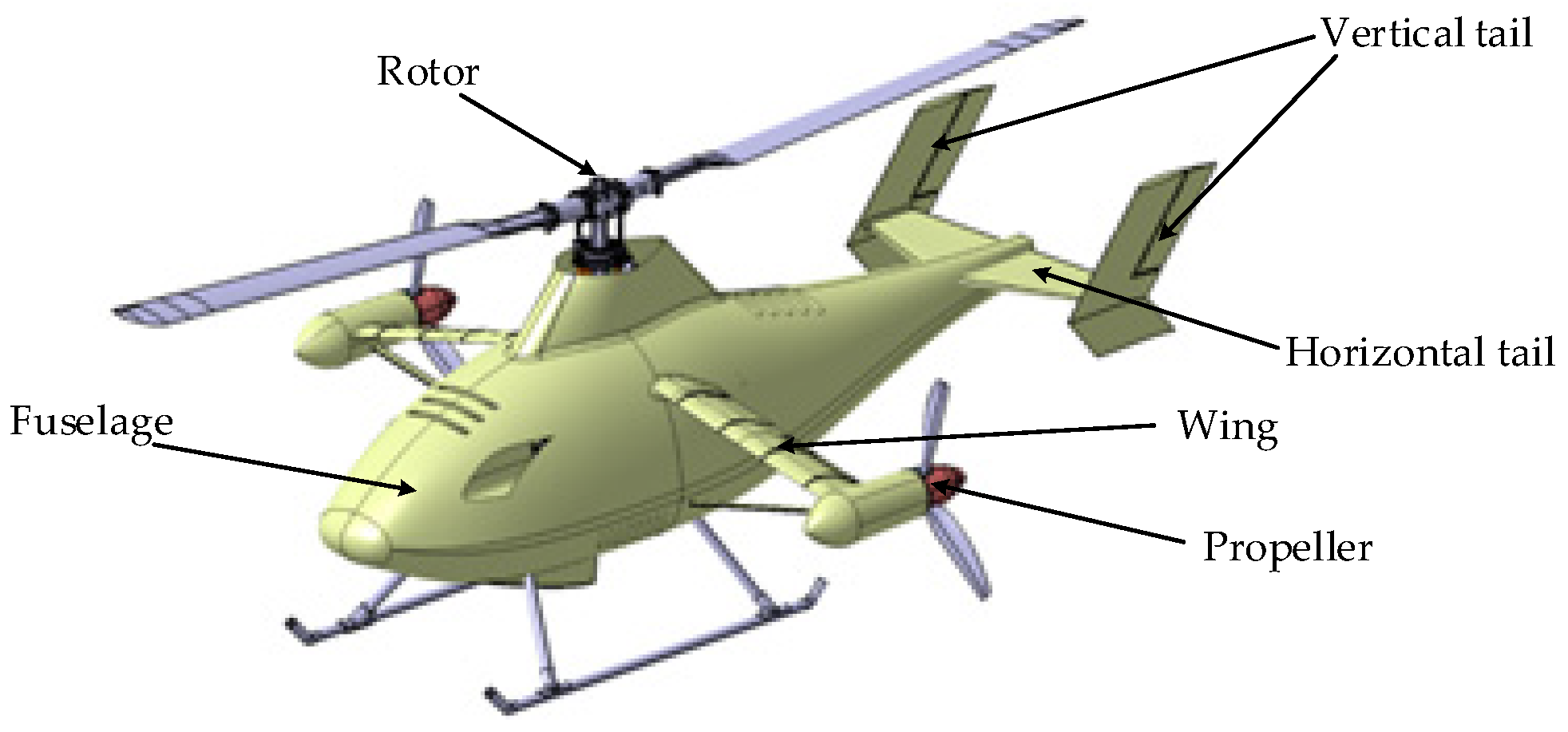
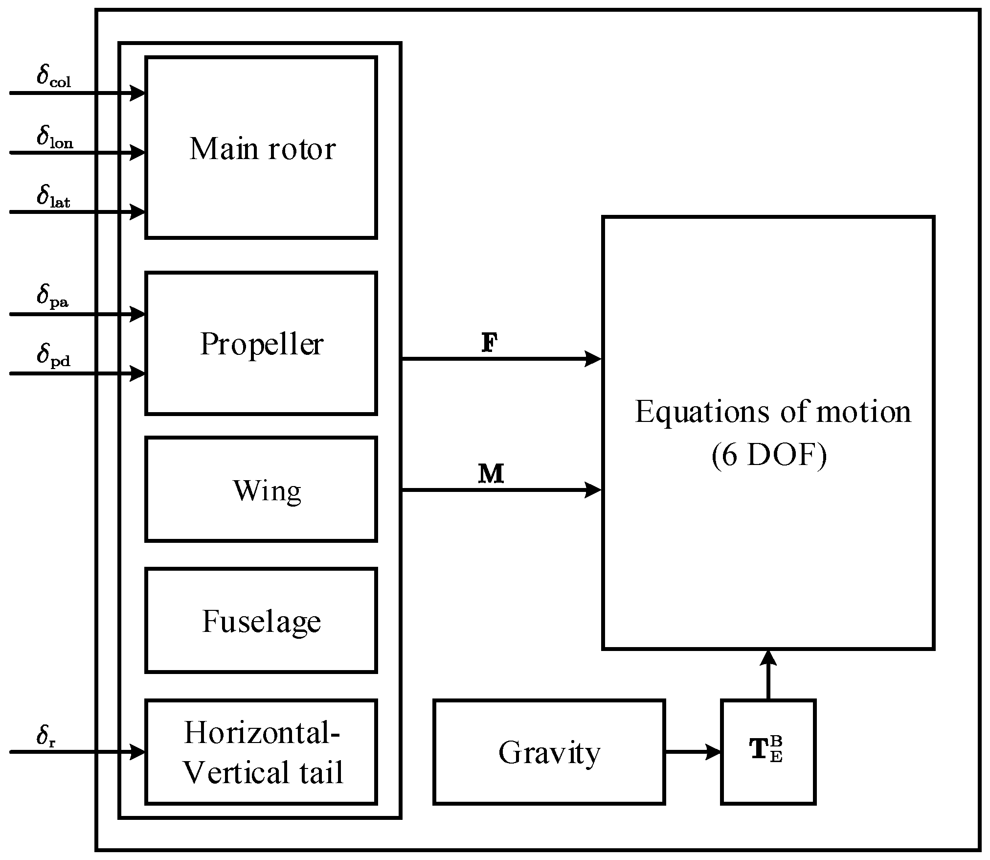
  • The incorporation of aerodynamic interference factors has enabled a comprehensive aerodynamic modeling of the various components of the unmanned compound rotorcraft, including the wing, fuselage, and both the horizontal and vertical tails. Building upon this modeling process, a nonlinear flight dynamics model has been developed specifically for the sample unmanned compound rotorcraft, which facilitates a deeper understanding of its flight behaviors and performance.
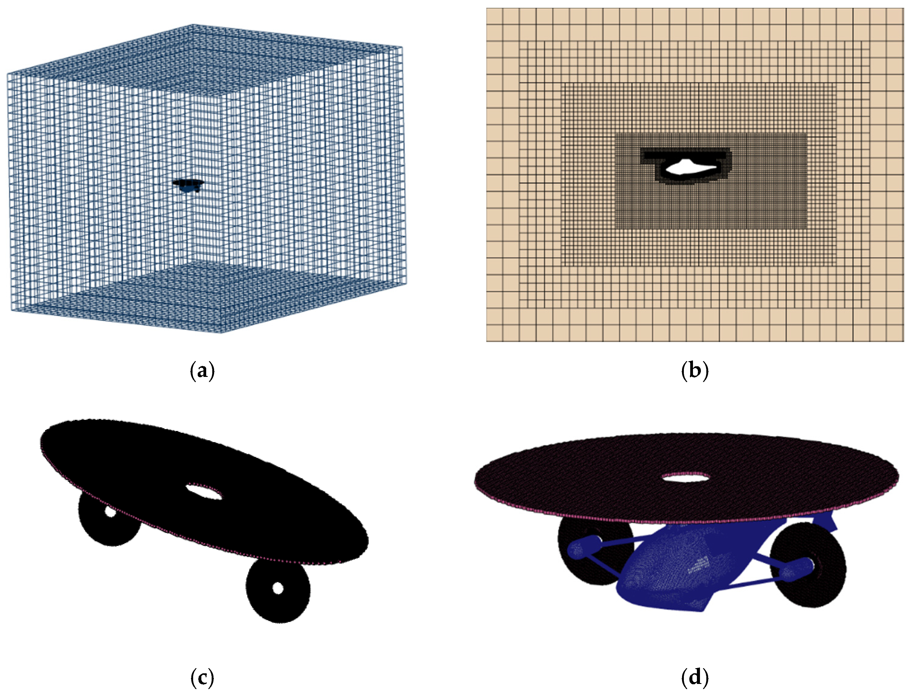
  • Based on the MSM, simulations of the flow fields for both the rotor and propeller have been conducted, and the isolated rotor case has been verified in hover. Subsequently, considering the characteristics of the unmanned compound rotorcraft model, a combination of unstructured and structured mesh suitable for interference flow field calculations of unmanned compound rotorcraft are proposed. Additionally, a detailed calculation and analysis of the aerodynamic interactions among the rotor, propeller, and fuselage of the unmanned compound rotorcraft are undertaken.
  • The nonlinear model of the unmanned compound rotorcraft is trimmed in simulations, and the outcomes are analyzed alongside data from the wind tunnel tests to validate the reliability of the revised flight dynamics model.

2. Flight Dynamics Model of the Unmanned Compound Rotorcraft

2.1. Overview of the Sample Unmanned Compound Rotorcraft

The unmanned compound rotorcraft analyzed in this paper is a creation of the China Aerodynamics Research and Development Center (CARDC) [19]. This rotorcraft is composed of several key components, including the rotor, propellers, wings, fuselage, and horizontal–vertical tail, which are illustrated in Figure 1. The rotor is responsible for generating the primary lift necessary for flight, while also facilitating pitch and roll control, which are essential for maneuverability. The wing providing auxiliary lift for lift compounding, thereby enhancing the overall aerodynamic efficiency of the rotorcraft. At both ends of the wing, the variable-pitch propellers serve a dual purpose. They not only produce forward thrust, propelling the unmanned compound rotorcraft through the air, but they also counterbalance the effects of anti-torque, ensuring stable flight. Furthermore, the horizontal–vertical tail is designed to improve pitch and yaw stability, which is vital for maintaining control during various flight conditions. Additionally, the rudder is used for yaw control.
The flight dynamics model for the unmanned compound rotorcraft consists of rigid body kinematic equations, aerodynamic models for each component, and coordinate transformation matrices, as shown in Figure 2. The modeling approach is as follows: First, the aerodynamic models for the rotor, propellers, fuselage, wing, and horizontal–vertical tail are developed separately. Then, the total aerodynamic forces and moments are synthesized at the center of gravity of the unmanned compound rotorcraft. Finally, the total aerodynamic forces, moments, and gravity are substituted into the rigid body kinematic equations. Using this systematic approach, the complete flight dynamics model for the unmanned compound rotorcraft is derived.
In Figure 2, δ col , δ lon , δ lat , δ pa , δ pd , δ r represent the control inputs of the unmanned compound rotorcraft. F and M represent the external forces and moments of the unmanned compound rotorcraft. T E B is the coordinate transformation matrix, expressed as follows:
T E B = cos θ cos ψ cos θ sin ψ sin θ sin ϕ sin θ cos ψ cos ϕ sin ψ sin ϕ sin θ sin ψ + cos ϕ cos ψ sin ϕ cos θ cos ϕ sin θ cos ψ + sin ϕ sin ψ cos ϕ sin θ sin ψ sin ϕ cos ψ cos ϕ cos θ
where Θ = ϕ , θ , ψ T represent the attitude angles of the unmanned compound rotorcraft.

2.2. Kinematic Equations

Accurately and comprehensively calculating the rotor dynamics of the unmanned compound rotorcraft is extremely complex and challenging. Moreover, the high-order flight dynamics model is difficult to analyze and design controllers. Therefore, making reasonable assumptions during the modeling of the unmanned compound rotorcraft is necessary. Based on this, the assumptions made in this paper are as follows [20]:
  • The ground coordinate system is considered to be an inertial reference system;
  • The gyroscopic effect caused by rotating components is neglected;
  • The longitudinal and lateral coupling effects are ignored;
  • The flapping motion of the propellers is neglected.
Based on these assumptions, the unmanned compound rotorcraft can be treated as an ideal rigid body. The kinematic equations are described using the Newton–Euler equations as follows:
v ˙ = ω × v + T E B g + F m
ω ˙ = I 1 ω × I ω + I 1 M
where v = u , v , w T and ω = p , q , r T are the linear velocities and angular velocities of the unmanned compound rotorcraft. m is the mass of the unmanned compound rotorcraft, g = 0 , 0 , g T is the gravitational acceleration. I 3 × 3 is the inertia matrix of the unmanned compound rotorcraft. The expressions for F = X , Y , Z T and M = L , M , N T are as follows:
F = F mr + F pl + F pr + F w + F f + F h M = M mr + M pl + M pr + M w + M f + M h
Furthermore, the attitude angles and angular velocities satisfy the following motion equations:
ϕ ˙ = p + tan θ q sin ϕ + r cos ϕ θ ˙ = q cos ϕ r sin ϕ ψ ˙ = q sin ϕ + r cos ϕ cos θ

2.3. Aerodynamic Models of Each Component

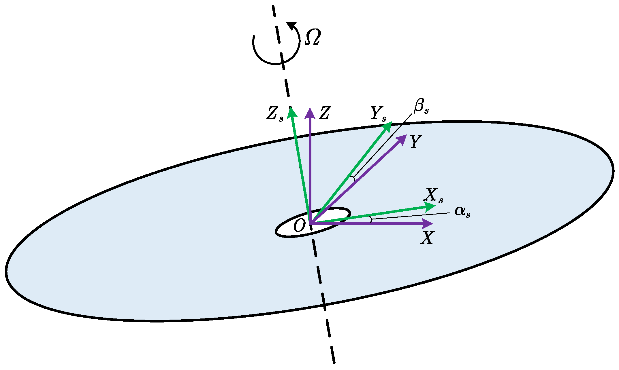
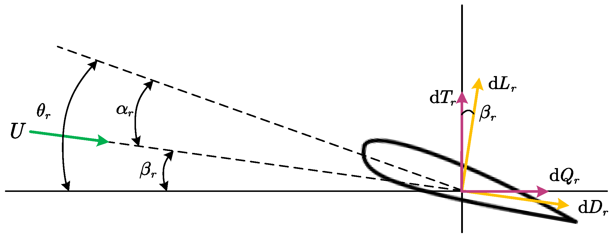
2.3.1. Rotor Aerodynamic Model

The key to rotor aerodynamic modeling lies in establishing appropriate models for flapping motion, dynamic inflow, and blade element aerodynamic calculations. In ref. [21], flapping motion is a periodic function related to the rotor angular velocity and blade azimuth angle. The equation governing flapping motion can be approximated using a first-order Fourier series:
β = β 0 β 1 c cos Ψ β 1 s sin Ψ
where the constant term β 0 represents the coning angle. Since the sample unmanned compound rotorcraft uses a hinged-free rigid rotor, the coning angle β 0 = 0 is zero. In ref. [22], the longitudinal and lateral flapping angles β 1 c , β 1 s can be approximately calculated using the following equations:
τ f β ˙ 1 c = β 1 c τ f q + 8 K β γ b Ω 2 I b β 1 s + A lon δ lon
τ f β ˙ 1 s = β 1 s τ f p + 8 K β γ b Ω 2 I b β 1 c + B lat δ lat
where I b is the blade inertia, while A lon and B lat are steady-state gains that represent the variation in longitudinal and lateral flapping angles in response to the cyclic control inputs. τ f and γ b are the flapping time constants and blade Lock numbers, respectively, with the following expressions:
τ f = 16 γ b Ω
γ b = ρ c C l α R 4 I b
where ρ represents the density of air, c denotes the length of the blade chord, and C l α indicates the lift slope of the blade.
In this paper, the Pitt-Peters dynamic inflow model is utilized to ascertain the rotor’s induced velocity. This approach considers the gradient distribution of the rotor-induced velocity across the blade span and the azimuth angle [23,24], specifically
v i = v 0 + v 1 c r ¯ cos Ψ + v 1 s r ¯ sin Ψ
where v0, v1c, v1s denote the time-averaged, first-order longitudinal, and lateral inflow components, respectively, while r ¯ is the radial position. The mathematical description of the inflow equation is given by the following:
M v ˙ 0 v ˙ 1 s v ˙ 1 c + V L 1 v 0 v 1 s v 1 c = C T C L C M
where V represents the mass flow parameter matrix, while M denotes the apparent mass matrix. L indicates the wake-induced inflow gain matrix.
The aerodynamic forces and moments of the rotor are given by the following:
X mr Y mr Z mr = cos δ 0 sin δ 0 1 0 sin δ 0 cos δ H S T
L mr M mr N mr = cos δ 0 sin δ 0 1 0 sin δ 0 cos δ M G x M G y M k + X mr Y mr Z mr × x mr y mr z mr
where δ denotes the tilt angle of the rotor and [ x mr , y mr , z mr ] T represent the coordinates of the rotor hub center. H, S, T denote the rotor’s aft force, lateral force, and thrust, respectively. Although the derivation process is complex, it follows a relatively straightforward approach. Detailed derivation can be found in ref. [25]. MGx, MGy, Mk correspond to the hub roll moment, pitch moment, and the rotor-induced anti-torque, respectively.

2.3.2. Propeller Aerodynamic Model

Under basic assumptions, the aerodynamic modeling of the propeller follows a similar approach to that of the rotor. In line with the concepts of blade element theory, the aerodynamic forces and moments produced by the propellers can be represented as follows:
X p Y p Z p = T p 0 0
L p M p N p = τ p 0 0 + X p Y p Z p × x p y p z p
where Tp represents the propeller thrust, τ p denotes the anti-torque produced by the propeller, and [ x p , y p , z p ] T represent the coordinates of the propeller hub center.

2.3.3. Aerodynamic Models of the Wing, Fuselage, and Horizontal–Vertical Tail

The aerodynamic model of the wing, fuselage, and horizontal–vertical tail of the unmanned compound rotorcraft is characterized by a high degree of complexity. Given the influences of rotor downwash and propeller slipstream, the aerodynamic modeling of these components must consider not only their own aerodynamic forces, but also the interactions induced by the rotor and propellers [26]. Therefore, this paper introduces aerodynamic interference factors to updated the aerodynamic models.
The wing’s aerodynamic model is given by the following:
L wi = 1 2 ρ V w 2 C lw A w K lw
D wi = 1 2 ρ V w 2 C dw A w K dw
where C1w, Cdw represent the lift and drag coefficients of the wing. Vw denotes the relative airflow velocity at the aerodynamic center of the wing, and Aw is the effective wing area. K1w, Kdw represent the lift and drag interference factors, defined as follows:
K lw = L wr w L w K dw = D wr w D w
where L w and L wr w represent the lift produced by the wing in the absence of and in conjunction with the rotor and propellers. Similarly, D w and D wr w denote the drag experienced by the wing without and with the rotor and propellers.
The fuselage aerodynamic model is expressed as follows:
L fi = 1 2 ρ V f 2 C lf A f K lf
D wi = 1 2 ρ V f 2 C df A f K df
where C1f, Cdf represent the lift and drag coefficients of the fuselage, Vf denotes the relative airflow velocity at the aerodynamic center of the fuselage, and Af is the effective fuselage area. K1f, Kdf represent the lift and drag interference factors, defined as follows:
K lf = L fr f L f K df = D fr f D f
where Lf and L fr f represent the lift generated by the fuselage in the absence of and in conjunction with the rotor and propellers. Likewise, Df and D fr f denote the drag experienced by the fuselage without and with the rotor and propellers, respectively.
The horizontal-vertical tail aerodynamic model is given by the following:
L hvi = 1 2 ρ V hv 2 C lhv A hv K lhv
D hvi = 1 2 ρ V hv 2 C dhv A hv K dhv
where Clhv, Cdhv represent the lift and drag coefficients of the horizontal–vertical tail. Vhv represents the relative airflow velocity at the aerodynamic center of the horizontal–vertical tail, and Ahv is the effective tail area. Klhv, Kdhv represent the lift and drag interference factors, defined as follows:
K lhv = L hvr hv L hv K dhv = D hvr hv D hv
where Lhv and Lhv represent the lift generated by the horizontal–vertical tail in the absence of and in conjunction with the rotor and propellers. Similarly, D hv and D hvr hv denote the drag experienced by the horizontal–vertical tail without and with the rotor and propellers, respectively.

3. Calculation Method and Validation

3.1. Introduction to the MSM

Based on momentum-blade element theory, the MSM is widely applied for simulating the aerodynamic characteristics of rotors [27,28]. The fundamental idea is to approximate the rotating blades as a virtual disk, where the effect of the blades on the airflow is represented as a time-averaged momentum source term directly incorporated into the momentum equations. Compared to the moving nested grid method, the MSM reduces the complexity of mesh generation and decreases the number of grid cells, thereby achieving a balance between computational accuracy and efficiency [29].

3.1.1. Governing Equation

To improve computational accuracy, this study applies the three-dimensional unsteady Reynolds-averaged Navier–Stokes (RANS) equation as the governing equation:
t V W d V + S F W G W d S = 0
where W represents the conserved variables and F W , G W denote the inviscid flux and viscous flux, respectively.

3.1.2. Rotor Momentum Source Model

The coordinate systems for the computational domain and the rotor disk are illustrated in Figure 3. In Figure 3, α s , β s represent the rotor disk’s tilt angles in the longitudinal and lateral directions, respectively. The transformation matrix that relates the two coordinate systems is given by the following:
T c s = cos α s sin β s sin α s cos β s sin α s 0 cos α s sin β s sin α s sin β s cos α s cos β s cos α s
The aerodynamic force calculation for the airfoil section is illustrated in Figure 4.
The lift and drag of the airfoil section are given by the following:
d L r = 1 2 ρ U 2 C L c d r
d D r = 1 2 ρ U 2 C D c d r
The airfoil thrust d T r and airfoil drag d Q r are given by the following:
d T r = d L r cos β r d D r sin β r
d Q r = d D r cos d β r + d L r sin β r
Since there is no aerodynamic force in the spanwise direction of the blade section, it follows that d H s = 0 . The aerodynamic resultant force d F r = d H r , d T r , d Q r T of the blade section is then transformed into the computational domain coordinate system as follows:
d F c = T c s T d F r
Thus, the force exerted by a blade element in the flow field is given by d F c . Finally, the computed force is added to the time-averaged momentum source term S r = S r x , S r y , S r z T , which is calculated as follows:
S = N Δ φ 2 π d F c
where N is the number of blades and Δ φ represents the distance a blade travels through the blade element unit.

3.2. Mesh Generation

The convergence of calculations and the precision of results are directly influenced by the quality of the mesh. Therefore, high-quality computational mesh must be generated to ensure the correctness of the CFD simulations [30,31,32]. Considering both computational efficiency and accuracy, a cube with dimensions 10 L × 8 L × 8 L (L is the fuselage length) was chosen as the computational domain. The fuselage is accompanied by a structured mesh throughout the flow area. Since the rotor flow field is modeled using the MSM, virtual disk representations are used for both the rotor and the propellers. To minimize computational errors, structured mesh is applied to the rotor and propeller regions, while unstructured mesh is used for the fuselage. The final grid for the calculation contains 4,511,836 points, 13,406,876 faces, and 4,556,006 cells. Figure 5 illustrates the computational mesh for the unmanned compound rotorcraft.
In addition, the boundary conditions for the computational domain are outlined as follows: the inlet is defined as the velocity inlet, the outlet is designated as the pressure outlet, the fuselage surface adopts the non-slip wall boundary, and the rotor and propellers domains are simulated by the MSM. The solver uses a pressure based transient coupling solver, and the SIMPLE algorithm is adopted to deal with the pressure–velocity coupling. The turbulence model adopts the SST k ω model to accurately capture the flow separation and rotor wake evolution characteristics in the near-wall domain. A mixed mesh strategy is adopted for grid division. Prismatic layer grids are generated on the fuselage surface to ensure boundary layer resolution. The total number of prismatic layers is 15 to meet the requirements for solving the boundary layer velocity gradient. The time discretization adopts a second-order implicit format, with a time step of 1/720 of the rotor rotation period (corresponding to a 0.5° azimuth change). The convergence criterion is set as the continuity equation residuals fall below 10−4.

3.3. Validation of the Calculation Method

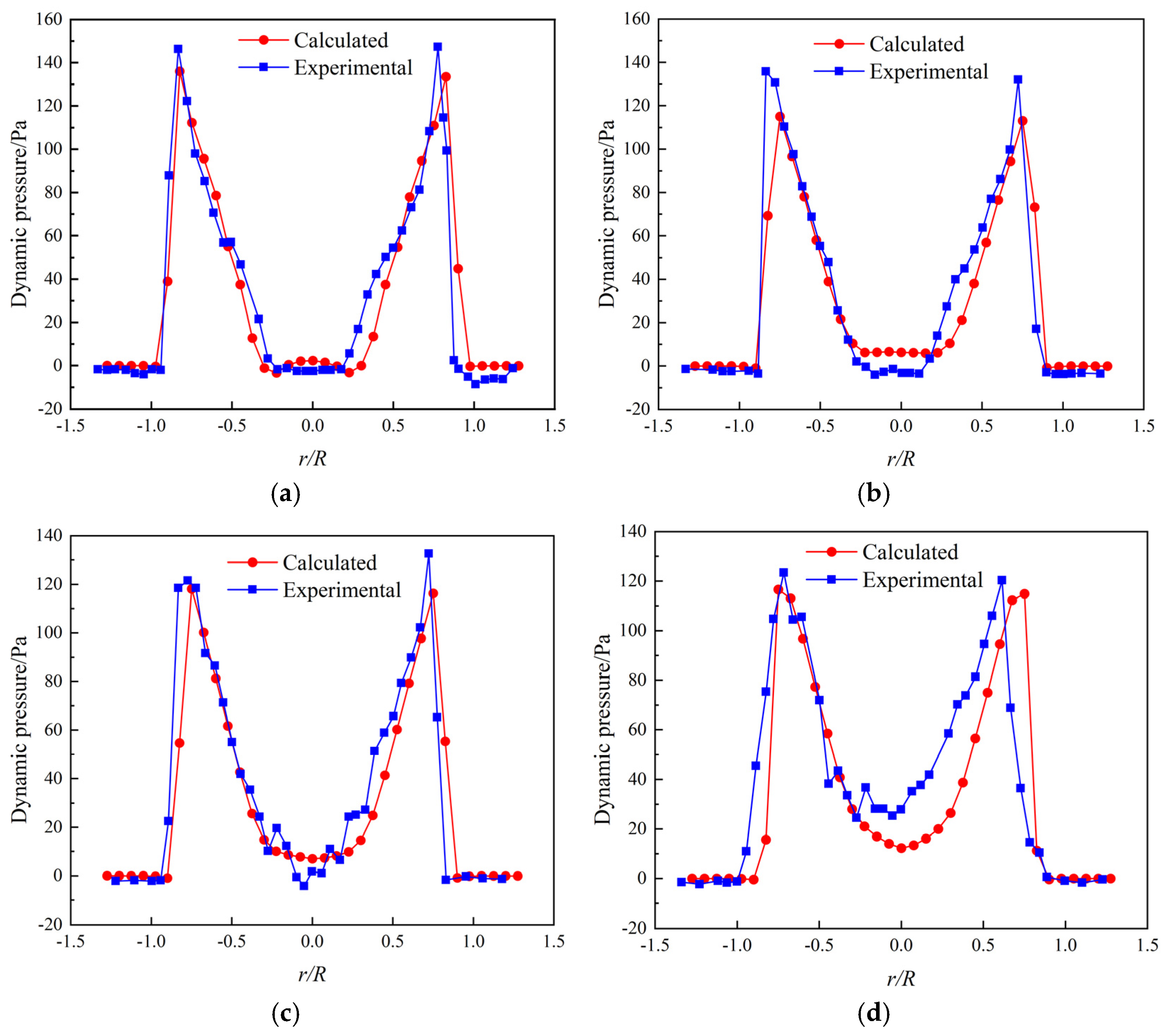
3.3.1. Isolated Rotor Calculation Verification

To assess the practicality and efficiency of the MSM in modeling rotor conditions, a rotor model from the ref. [33] is used as a case study. The dynamic pressure values at different heights beneath the rotor disk in hover state are computed and compared with experimental data. Table 1 presents the pertinent parameters of the rotor utilized in the case study.
Figure 6 illustrates the results of comparing the calculated dynamic pressure values with the experimental values at various heights below the rotor disk.
As illustrated in Figure 6, the calculated dynamic pressure values along the radial direction at various heights beneath the rotor disk match the experimental data closely. The overall trend of change is the same, and the dynamic pressure at different heights shows a symmetric distribution, which is in accordance with the rotor flow field characteristics during hover conditions. This indicates that the rotor MSM used in this study is effective in simulating rotor conditions.

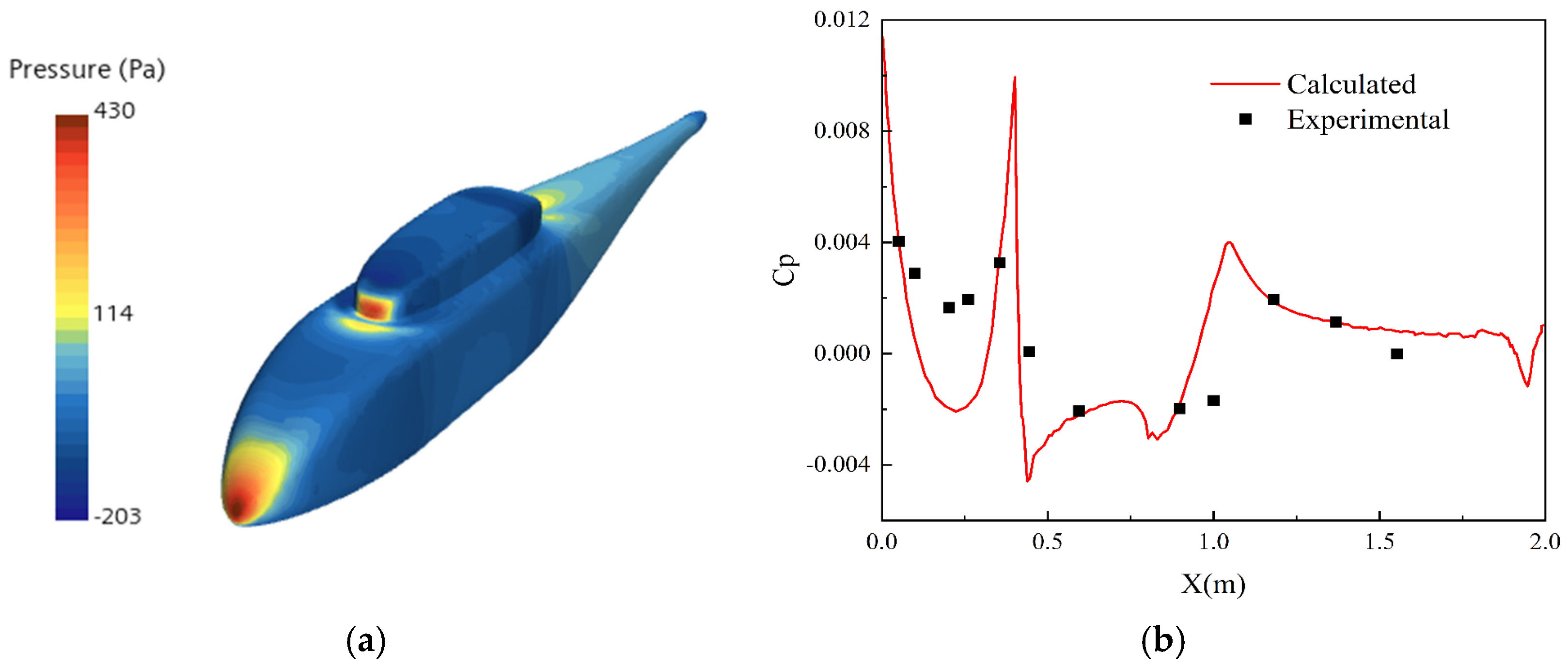
3.3.2. Rotor/Fuselage Interference Calculation Verification

To verify the precision of the MSM in addressing the rotor/fuselage interference problem, the ROBIN model in ref. [34] is adopted to assess the pressure distribution on the fuselage surface affected by aerodynamic interference. These results are then compared with experimental data. Table 2 presents the essential parameters of the calculation example.
The rotor/fuselage interference flow field with a forward ratio of 0.15 is calculated. In Figure 7a, the distribution of pressure across the fuselage surface is depicted, whereas Figure 7b shows a comparison between the calculated pressure coefficient values and the experimental data collected from the upper section of the fuselage.
As illustrated in Figure 7a, the distribution of pressure across the fuselage displays an asymmetry, attributed to the non-uniformity of the relative airflow on the plane of rotation of the rotor and the influence of cyclic controls during forward flight. This leads to an uneven downwash airflow from the rotor. In Figure 7b, it can be observed that the computed pressure coefficient along the upper fuselage line closely aligns with the results obtained from tests. Moreover, the distribution of the computed high-pressure region also corresponds well with the experimental findings, suggesting that the MSM effectively replicates the flow field resulting from rotor/fuselage interactions during forward flight.

4. Aerodynamic Interference Analysis of the Rotor/Propeller/Fuselage in Forward Flight

The aerodynamic interference among the components of conventional rotorcrafts is relatively minor, mainly focusing on how the rotor downwash affects the fuselage. However, when it comes to unmanned compound rotorcraft, one must take into account not just the rotor downwash, but also the effects of the propellers [35]. During forward flight, both the rotor downwash and the propeller slipstream exert direct influence on the wing, fuselage, and horizontal–vertical tail surfaces of the unmanned compound rotorcraft, creating considerable downward forces that subsequently influence their aerodynamic properties.

4.1. Rotor/Propeller Slipstream Analysis

To comprehensively investigate the impacts of the rotor and propellers on the crucial components of the unmanned compound rotorcraft, such as the wing, fuselage, and horizontal–vertical tail during forward flight, a set of six critical velocity points ranging from 10 m/s to 60 m/s has been identified within the flight speed envelope. These points cover the unmanned compound rotorcraft’s flight states from low speed to high speed. To gain insights into the aerodynamic interactions occurring at these different flight speeds, CFD calculations are conducted for both isolated fuselage and rotor/propeller/fuselage combined states. The primary goal of this analysis is to understand how the slipstreams generated by the rotor and propeller influence the dynamics of the wing, fuselage, and horizontal–vertical tail in the rotor/propeller/fuselage combined state. The outcomes of the CFD simulations are visually represented in Figure 8, which illustrates the velocity distribution along the longitudinal section of the unmanned compound rotorcraft at various forward flight speeds in the rotor/propeller/fuselage combined state.
Based on Figure 8, the slipstreams generated by the rotor and propeller are somewhat redirected due to the effect of forward flight at lower speeds. While the angle of deflection is comparatively minor, it can nonetheless cause aerodynamic interactions with the fuselage. As the speed of flight rises, the slipstream deflection angle diminishes and eventually aligns horizontally.

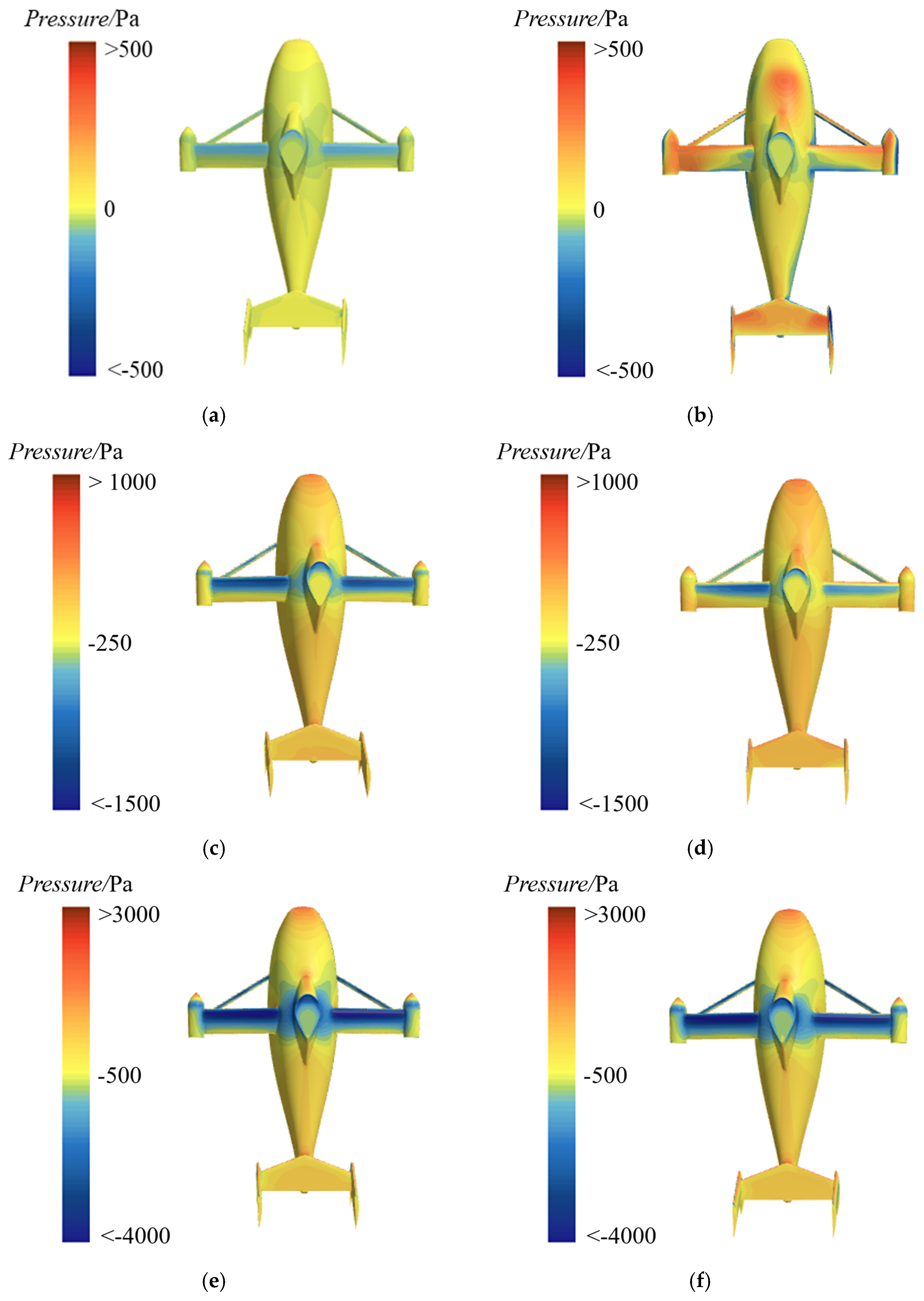
4.2. Pressure Distribution

To analyze the pressure distribution across the surface of the unmanned compound rotorcraft’s fuselage, three typical flight states at forward speeds of 10 m/s, 30 m/s, and 60 m/s are selected. Figure 9 illustrates the pressure distribution of the fuselage in both the isolated fuselage state and the rotor/propeller/fuselage combined state.
As illustrated in Figure 9, at low forward speeds, the pressure exerted on the wing surface in the rotor/propeller/fuselage combined state is the highest. This is primarily due to the direct impact of the rotor downwash and propeller slipstream on the upper surface of the wing, leading to an increase in pressure. With an elevation in forward flight speed, there is a gradual decline in the pressure on the wing surface. When the forward flight speed reaches V = 60 m/s, the pressure on the wing surface in the rotor/propeller/fuselage combined state is nearly the same as that in the isolated fuselage state, indicating that the disruptive effects of the rotor and propellers on the wing diminish as the flight speed increases. Similarly, the pressure distribution on the fuselage surface in the rotor/propeller/fuselage combined state exhibits a comparable trend to that seen on the wing. As the flight speed increases, the pressure on the fuselage surface gradually decreases and eventually becomes similar to the pressure in the isolated fuselage state, suggesting that the interference from the rotor and propellers on the fuselage weakens as the flight speed increases. In comparison to the fuselage and wing, the pressure on the horizontal–vertical tail surface in the rotor/propeller/fuselage combined state is the highest at the same forward speed. This indicates that the interference caused by the rotor and propellers on the horizontal–vertical tail is the most pronounced. Furthermore, as the forward speed increases, the pressure on the tail surface gradually decreases, and the interference from the rotor and propellers on the tail weakens.

4.3. Update of Aerodynamic Models

Flight dynamics modeling is the foundation for analyzing controllability and stability, as well as designing flight control systems. To develop a more precise flight dynamics representation for the unmanned compound rotorcraft, it is essential to consider the interference effects caused by the rotor and propellers on the fuselage components throughout the aerodynamic modeling of each component. Consequently, this paper presents interference factors aimed at quantitatively characterizing the rotor’s influence on these components. By applying these interference factors to the aerodynamic model of the wing, fuselage, and horizontal–vertical tail, an accurate aerodynamic model accounting for the effects of rotor downwash and propeller slipstream can be developed.
By using the MSM to model the lift and drag characteristics of the wing, fuselage, and horizontal–vertical tail at various speed points in the rotor/propeller/fuselage combined state, and comparing them with the lift and drag generated in the isolated fuselage state, we can obtain the interference factors for the wing, fuselage, and horizontal–vertical tail due to rotor and propeller slipstream interference. In addition, this paper focuses on the aerodynamic interference factors at forward flight speeds of 30 m/s and above, conducting a thorough graphical analysis. The trends of lift and drag interference factors for the wing, fuselage, and horizontal–vertical tail with respect to forward flight speed are illustrated in Figure 10.
The information depicted in Figure 10a highlights a notable trend: an increase in flight speed results in a gradual reduction in the interference effects caused by the rotor and propellers on the lift generated by the wing, fuselage, and horizontal–vertical tail. This phenomenon occurs because the slipstreams from the rotor and propellers become more horizontal as forward flight speed increases, thereby diminishing the downwash impact on the aerodynamic components. This result is consistent with the previously discussed pressure distribution on the surfaces of the aerodynamic components, indicating that the impact of the rotor and propellers on pressure distribution weakens as the forward speed escalates. From Figure 10b, as the forward flight speed increases, the rotor and propellers’ interference with the drag on the wing remains relatively constant, with only a minor decrease noted. In contrast, the interference of the rotor and propellers concerning the drag of the horizontal–vertical tail is more significant. This suggests that the drag of the horizontal–vertical tail is more sensitive to the forward speed, and greater attention may be needed for the design and adjustment of the horizontal–vertical tail in the subsequent research and analysis. Conversely, the trend regarding the rotor’s interference on fuselage drag is less apparent, potentially suggesting that fuselage drag is either less influenced by rotor downwash or that the aerodynamic design of the fuselage maintains stability over varying forward flight speeds.

5. Model Validation

In ref. [15], a wind tunnel test for the sample unmanned compound rotorcraft was conducted. To validate the updated flight dynamics model of the sample unmanned compound rotorcraft, the previously updated flight dynamics model is trimmed in Simulink by employing the same parameters used in the wind tunnel test from ref. [15]. The results comparing the numerical simulation with the wind tunnel test are depicted in Figure 11.
As can be observed from Figure 11, the aerodynamic load simulation results, including rotor thrust, propeller thrust, and total lift, along with the control inputs for both the rotor and propellers, align well with the data obtained from wind tunnel tests across various forward flight speeds. This demonstrates that the updated flight dynamics model, which incorporates aerodynamic interference factors, accurately reflects the motion characteristics within the flight speed envelope and is highly reliable. Nevertheless, at lower speeds, a noticeable discrepancy appears between the numerical simulation results and the wind tunnel data. These discrepancies are primarily due to wind tunnel wall interference and support interference, which are absent in the CFD calculations and numerical simulations. In summary, the updated flight dynamics model provides a theoretical foundation for the stability and controllability analysis and flight simulation of the sample unmanned compound rotorcraft.

6. Conclusions

The key conclusions drawn from this paper are as follows:
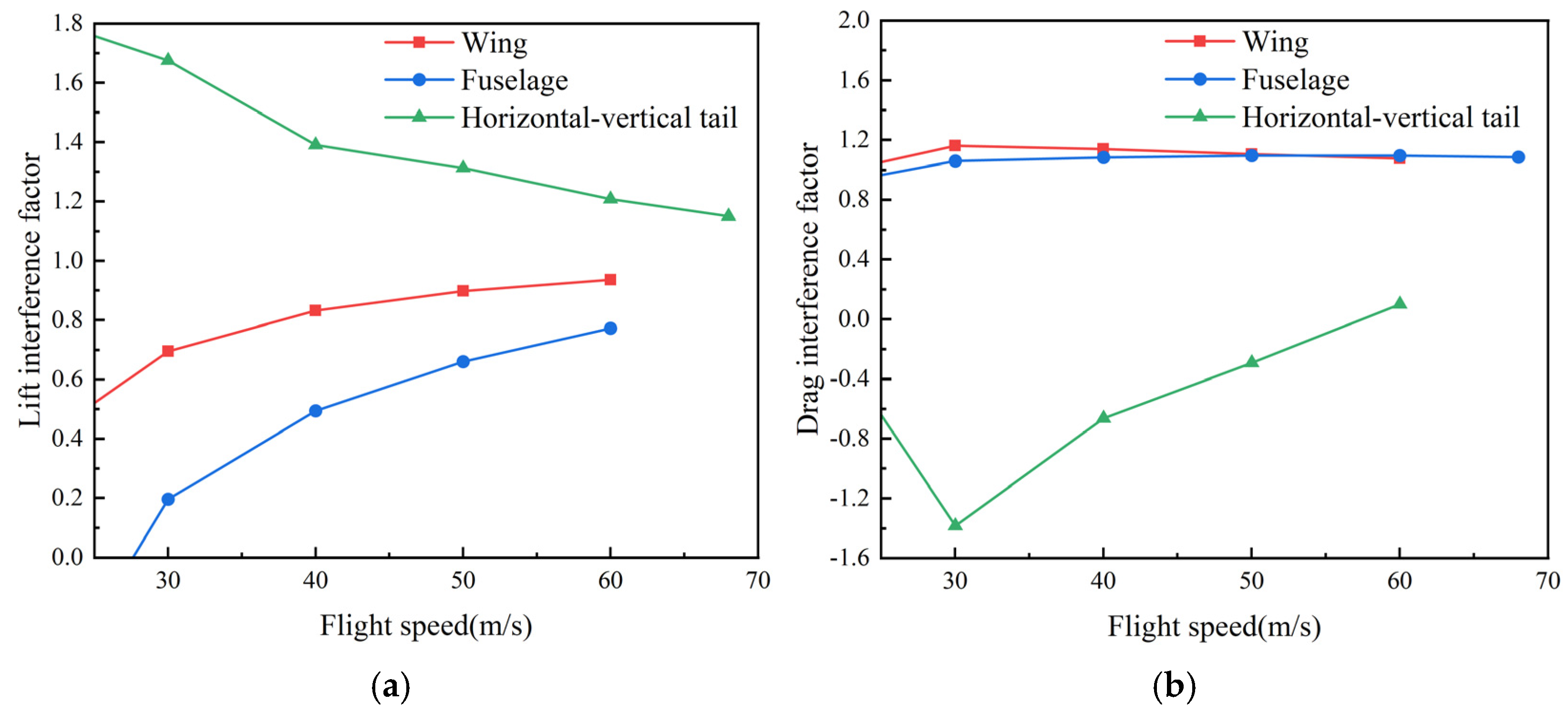
  • The MSM is utilized to analyze the aerodynamic interference of the unmanned compound rotorcraft. It has been observed that the downwash from the rotor has a considerable impact on the aerodynamic properties of the wing, fuselage, and horizontal–vertical tail. During low-speed forward flight (with speeds less than 20 m/s), the influence of the rotor and propeller on these components increases significantly. When the flight speed increases, the rotor downwash becomes more horizontal, leading to a gradual reduction in aerodynamic interference among these components. This phenomenon is consistently reflected in the surface pressure distribution of the wing and fuselage, as well as the trends in aerodynamic interference factors.
  • The aerodynamic interference factors obtained from CFD calculations show that the impact of the rotor and propellers on the wing, fuselage, and vertical tail varies considerably with changes in flight speed. Specifically, when the flight speed increases, the interference effects exerted by the rotor and propellers on the lift of these components gradually diminish. However, the influence on drag is not consistent. With a rise in forward flight speed, the interference effects on the horizontal–vertical tail become more pronounced, whereas those on the wing and fuselage remain relatively minor.
  • The numerical simulation results for the updated flight dynamics model, including rotor thrust, propeller thrust, total lift, and control inputs for the rotor and propeller at different forward flight speeds demonstrate excellent consistency with the wind tunnel test results. This validates the precision and dependability of the updated flight dynamics model.
Although this paper has achieved certain research results regarding the aerodynamic interference analysis and flight dynamics modeling considering the rotor/propeller/fuselage of the unmanned compound rotorcraft, the aerodynamic interference of the unmanned compound rotorcraft remains a complex issue, with many significant aspects still worthy of further study. In the future, we will consider the aerodynamic interference effects under more complex conditions. Additionally, we will proceed to design and verify flight control laws based on the updated flight dynamics model, followed by flight tests to validate the applicability of the established updated flight dynamics model.

Author Contributions

Conceptualization, X.Y.; methodology, H.M.; software, X.Y. and B.N.; validation, C.W. and B.N.; formal analysis, H.A.; investigation, H.D.; resources, S.J. and L.H.; data curation, C.W.; writing—original draft preparation, X.Y.; writing—review and editing, H.M., H.A. and L.H.; visualization, S.J. and H.A.; supervision, H.M. and H.D.; project administration, C.W.; funding acquisition, X.Y. All authors have read and agreed to the published version of the manuscript.

Funding

This research was funded by the Graduate Innovation Program of National University of Defense Technology, grant number XJQY2024025 and the Zhiqiang fund.

Data Availability Statement

The data presented in this study are available upon reasonable request from the corresponding author.

Acknowledgments

The authors would like to thank the editors and the reviewers for their insightful comments and suggestions for improving the quality of this paper.

Conflicts of Interest

The authors declare no conflicts of interest.

References

  1. Yan, X.; Lou, B.; Xie, A.; Chen, L.; Zhang, D. A review of advanced high-speed rotorcraft. IOP Conf. Ser. Mater. Sci. Eng. 2021, 1102, 012006. [Google Scholar] [CrossRef]
  2. Tanabe, Y.; Sugiura, M.; Kobiki, N.; Sugawara, H. A new concept of compound helicopter and flight tests. In Proceedings of the 2018 Asia-Pacific International Symposium on Aerospace Technology, Chengdu, China, 16–18 October 2018; pp. 1343–1352. [Google Scholar]
  3. Airbus Racer Speeds Past 400 km/h. Available online: https://www.airbus.com/en/newsroom/press-releases/2024-07-airbus-racer-speeds-past-400-kmh (accessed on 21 June 2024).
  4. Yang, K.L.; Han, D. Influence of rotor/wing aerodynamic interference on performance of compound helicopters. J. Beijing Univ. Aeronaut. Astronaut. 2023, 49, 1761–1771. [Google Scholar]
  5. Li, B.; Liang, D.W.; Huang, G.P. Propeller slipstream effects on aerodynamic performance of turbo-prop airplane based on equivalent actuator disk model. Acta Aeronaut. Astronaut. Sin. 2008, 29, 845–852. [Google Scholar]
  6. Ferguson, K.; Thomson, D. Flight dynamics investigation of compound helicopter configurations. J. Aircr. 2015, 52, 156–167. [Google Scholar] [CrossRef]
  7. Roche, J. Aerodynamic Trade Study of Compound Helicopter Concepts. Master’s Thesis, Embry-Riddle Aeronautical University, Daytona Beach, FL, USA, 2015. [Google Scholar]
  8. Wagter, C.; Smeur, E. Control of a hybrid helicopter with wings. Int. J. Micro Air Veh. 2017, 9, 209–217. [Google Scholar] [CrossRef]
  9. Ye, L.; Zhang, Y.; Yang, S.; Zhu, X.; Dong, J. Numerical simulation of aerodynamic interaction for a tilt rotor aircraft in helicopter mode. Chin. J. Aeronaut. 2016, 29, 843–854. [Google Scholar] [CrossRef]
  10. Colli, A.; Zanotti, A.; Gibertini, G. Wind-tunnel experimental investigation on rotor-rotor aerodynamic interaction in compound helicopter configuration. Aerosp. Sci. Technol. 2024, 153, 109420. [Google Scholar] [CrossRef]
  11. Frey, F.; Thiemeier, J.; Öhrle, C.; Keßler, M.; Krämer, E. Aerodynamic interactions on airbus helicopters’ compound helicopter RACER in hover. J. Am. Helicopter Soc. 2022, 67, 1–17. [Google Scholar] [CrossRef]
  12. Frey, F.; Thiemeier, J.; Öhrle, C.; Keßler, M.; Krämer, E. Aerodynamic interactions on Airbus Helicopters’ compound helicopter RACER in cruise flight. In Proceedings of the Vertical Flight Society 75th Annual Forum, Philadelphia, PA, USA, 13–16 May 2019; pp. 1–19. [Google Scholar]
  13. Lienard, C.; Salah, I.; Renaud, T. RACER high-speed demonstrator: Rotor and rotor-head wake interactions with tail unit. In Proceedings of the Vertical Flight Society 80th Annual Forum, Montreal, QC, Canada, 7–9 May 2019; pp. 1–13. [Google Scholar]
  14. Sugawara, H.; Tanabe, Y. Numerical investigation of rotor/wing aerodynamic interactions at high advance ratios. J. Aircr. 2019, 56, 2285–2298. [Google Scholar] [CrossRef]
  15. Nie, B.; Wang, L.; Huang, Z.; He, L.; Yang, S.; Yan, H.; Zhang, G. Flight dynamics modeling and control scheme design of compound high-speed unmanned helicopters. Acta Aeronaut. Astronaut. Sin. 2024, 45, 129–148. [Google Scholar]
  16. Lin, L.; Liu, X.; Peng, M.; Li, J. Research on flight dynamic modeling and interference of components for rotor/wing compound helicopter. In Proceedings of the 2018 Asia-Pacific International Symposium on Aerospace Technology, Chengdu, China, 16–18 October 2018; pp. 1202–1221. [Google Scholar]
  17. Huang, L.Y.; Zhao, X.; Wen, L. Analysis of aerodynamic trim and rotor/propeller/wing interference characteristics for high-speed composite helicopter in hover. In Proceedings of the 2023 Asia-Pacific International Symposium on Aerospace Technology, Lingshui, China, 16–17 October 2023; pp. 375–393. [Google Scholar]
  18. Kong, H.W. Research on Some Key Technical Issues of Compound High Speed Helicopter. Ph.D. Thesis, Nanjing University of Aeronautics and Astronautics, Nanjing, China, 2011. [Google Scholar]
  19. Xu, D.X.; Yang, S.P.; He, L. Investigation on propeller aerodynamic characteristics of compound high-speed helicopter. Helicopter Tech. 2024, 222, 4–9. [Google Scholar]
  20. Lu, K.; Liu, C.; Li, C.; Chen, R. Flight dynamics modeling and dynamic stability analysis of tilt-rotor aircraft. Int. J. Aerosp. Eng. 2019, 2019, 5737212. [Google Scholar] [CrossRef]
  21. Gavrilets, V.; Martinos, I.; Mettler, B.; Feron, E. Control logic for automated aerobatic flight of a miniature helicopter. In Proceedings of the AIAA Guidance, Navigation, and Control Conference and Exhibit, Monterey, CA, USA, 5–8 August 2002. [Google Scholar]
  22. Mettler, B. Identification Modeling and Characteristics of Miniature Rotorcraft, 2nd ed.; Springer: Boston, MA, USA, 2003. [Google Scholar]
  23. Pitt, D.M.; Peters, D.A. Theoretical prediction of dynamic-inflow derivatives. In Proceedings of the 6th European Rotorcraft and Powered Lift Aircraft Forum, Bristol, UK, 16–19 September 1980. [Google Scholar]
  24. Gaonkar, G.H.; Peters, D.A. Review of dynamic inflow modeling for rotorcraft flight dynamics. In Proceedings of the 27th Structures, Structural Dynamics and Materials Conference, San Antonio, TX, USA, 19–21 May 1986. [Google Scholar]
  25. Yin, X.; An, H.; Jia, S.; Ma, H.; Wang, C.; Wang, L.; Nie, B. Modeling and attitude disturbance rejection control of a compound high-speed helicopter with a new configuration. Int. J. Aeronaut. Space Sci. 2024. [Google Scholar] [CrossRef]
  26. Liu, C.F.; Zhu, Q.H.; Liu, J. Aerodynamic effect analysis of rotor downwash on wings of composite high-speed helicopter. Adv. Aeronaut. Sci. Eng. 2023, 14, 38–46. [Google Scholar]
  27. Zhao, Y.Y.; Li, X.; Shi, Y.J. Analysis on rotor-propellers interaction flowfield for compound double-thust-propeller high-speed helicopters. J. Nanjing Univ. Aeronaut. Astronaut. 2017, 49, 154–164. [Google Scholar]
  28. Fan, F.; Lin, Y.F.; Huang, S.L. Numerical simulation on rotor/fuselage unsteady interaction flowfield based on hybrid grid. J. Nanjing Univ. Aeronaut. Astronaut. 2015, 47, 180–188. [Google Scholar]
  29. Wang, X.Q.; Jiang, L.S.; Sun, H.X. Computational investigation of the dual-thrust compound high-speed helicopter aerodynamic interactions in hover. Helicopter Tech. 2024, 222, 15–21. [Google Scholar]
  30. Rajagopalan, R.G.; Baskaran, V.; Hollingsworth, A.; Lestarit, A.; Garrick, D.; Solis, E.; Hagerty, B. RotCFD—A tool for aerodynamic interference of rotors: Validation and capabilities. In Proceedings of the American Helicopter Society Future Vertical Lift Aircraft Design Conference, San Francisco, CA, USA, 18–20 January 2012. [Google Scholar]
  31. Koning, W.J.F.; Acree, C.W.; Rajagopalan, G. Using RotCFD to predict isolated XV-15 rotor performance. In Proceedings of the AHS Technical Meeting on Aeromechanics Design for Vertical Lift, San Francisco, CA, USA, 20–22 January 2016. [Google Scholar]
  32. Shen, J.; Fan, S.B.; Ji, Y.X. Aerodynamics analysis of a hypersonic electromagnetic gun launched projectile. Defence Technol. 2020, 16, 753–761. [Google Scholar] [CrossRef]
  33. Shen, S.Y.; Zhu, Q.H.; Zhu, Z.H.; Zhu, Q.-Y.; Duan, J. Analysis of rotor/propeller/fuselage interaction characteristics of high-speed helicopter. Adv. Aeronaut. Sci. Eng. 2020, 11, 46–55. [Google Scholar]
  34. Steijl, R.; Barakos, G. Sliding mesh algorithm for CFD analysis of helicopter rotor-fuselage aerodynamics. Int. J. Numer. Meth. Fluids 2008, 58, 527–549. [Google Scholar] [CrossRef]
  35. Stokkermans, T.; Veldhuis, L.; Soemarwoto, B.; Fukari, R.; Eglin, P. Breakdown of aerodynamic interactions for the lateral rotors on a compound helicopter. Aerosp. Sci. Technol. 2020, 101, 105845. [Google Scholar] [CrossRef]
Figure 1. The sample unmanned compound rotorcraft.
Drones 09 00329 g001
Figure 2. The flight dynamics model for the sample unmanned compound rotorcraft.
Drones 09 00329 g002
Figure 3. The computational domain coordinate system and the rotor disk coordinate system.
Drones 09 00329 g003
Figure 4. The schematic diagram of airfoil section.
Drones 09 00329 g004
Figure 5. Computational mesh for the sample unmanned compound rotorcraft. (a) Computational domain mesh; (b) mesh on the longitudinal cross-section of the computational domain; (c) rotor/propeller structured mesh; (d) fuselage mesh.
Drones 09 00329 g005
Figure 6. The results of comparing the calculated dynamic pressure values with the experimental values at various heights below the rotor disk. (a) 0.104R; (b) 0.215R; (c) 0.326R; (d) 0.660R.
Drones 09 00329 g006
Figure 7. The rotor/fuselage interference flow field with a forward ratio of 0.15 for ROBIN rotor/fuselage model. (a) The pressure distribution along the surface of the fuselage; (b) the comparison between the calculated pressure coefficient results and the experimental data from the upper line of the fuselage.
Drones 09 00329 g007
Figure 8. The velocity distribution along the longitudinal section of the unmanned compound rotorcraft at various forward flight speeds in the rotor/propeller/fuselage combined state. (a) V = 10 m/s; (b) V = 20 m/s; (c) V = 30 m/s; (d) V = 40 m/s; (e) V = 50 m/s; (f) V = 60 m/s.
Drones 09 00329 g008
Figure 9. The pressure distribution of the fuselage in both the isolated fuselage state and the rotor/propeller/fuselage combined state. (a) Isolated fuselage state (V = 10 m/s); (b) rotor/propeller/fuselage combined state (V = 10 m/s); (c) isolated fuselage state (V = 30 m/s); (d) rotor/propeller/fuselage combined state (V = 30 m/s); (e) isolated fuselage state (V = 60 m/s); (f) rotor/propeller/fuselage combined state (V = 60 m/s).
Drones 09 00329 g009
Figure 10. The trends in lift and drag interference factors for the wing, fuselage, and horizontal–vertical tail with respect to forward flight speed. (a) Lift interference factors; (b) drag interference factors.
Drones 09 00329 g010
Figure 11. The comparison results between the numerical simulation and wind tunnel test at different forward flight speeds.
Drones 09 00329 g011
Table 1. The relevant parameters of the rotor in the case study.
ParameterValueUnit
Number of rotor blades2-
Rotor radius0.914m
Rotor speed122.2rad/s
AirfoilNACA0012-
Chord length0.1m
Root cut0m
Twist0°
Collective pitch11°
Table 2. The essential parameters of the ROBIN rotor/fuselage model.
ParameterValueUnit
Number of rotor blades4-
Rotor radius0.86m
Rotor speed209.4rad/s
AirfoilNACA0012-
Chord length0.066m
Twist−8°
Disk solidityNACA0012-
Tip speed180m/s
Rotor/fuselage spacing0.083m
Fuselage length2m
Disclaimer/Publisher’s Note: The statements, opinions and data contained in all publications are solely those of the individual author(s) and contributor(s) and not of MDPI and/or the editor(s). MDPI and/or the editor(s) disclaim responsibility for any injury to people or property resulting from any ideas, methods, instructions or products referred to in the content.

