Article

Quadrotor Unmanned Aerial Vehicle-Mounted Launch Device Precision Analysis for Countering Intruding Drones

Coast Guard Academy, Naval Aviation University, Yantai 110016, China
*
Author to whom correspondence should be addressed.
Drones 2025, 9(1), 42; https://doi.org/10.3390/drones9010042
Submission received: 3 December 2024 / Revised: 1 January 2025 / Accepted: 6 January 2025 / Published: 9 January 2025
(This article belongs to the Section Drone Design and Development)

Abstract

:
In light of the current issue of commercial and modified drones frequently intruding into sensitive locations such as airports, this paper proposes the use of quadrotor drones equipped with a launch device for interception. For an “X”-shaped quadrotor drone equipped with a two-degree-of-freedom gimbal launch device, dynamic, control, and ballistic models are constructed to analyze the impact of single-shot firing on the drone’s attitude and the factors affecting accuracy in rapid-fire scenarios. Simulation results indicate that downward firing has the highest shooting accuracy and is suitable for counter-drone missions. For single-shot firing, lateral downward firing compared to frontal firing can effectively reduce attitude and position changes, which is beneficial for engaging stationary targets. In the case of rapid fire, control of the firing interval is crucial for accuracy; a larger firing interval can significantly enhance shooting precision. When firing small payloads in rapid succession, vertical downward firing has the highest accuracy, while lateral firing results in a larger distribution radius of the impact points. To improve shooting accuracy, frontal firing is recommended. Future research will further explore the dynamic response of drones under different firing conditions and develop more advanced control strategies to enhance their practical performance and reliability.

1. Introduction

Multi-rotor unmanned aerial vehicles (UAVs) have been widely applied in many fields due to their technological maturity, cost-effectiveness, and ease of control [1,2,3,4,5,6,7]. However, commercial and modified drones frequently intrude into sensitive areas such as airports and government facilities, posing a serious threat to security. Traditional anti-drone jammers mainly target drones that follow established communication protocols, and their effectiveness is limited against drones with modified communications [8,9]. In such cases, physical interception becomes an effective countermeasure, such as driving away or destroying intruding drones by launching capture nets or interceptor projectiles. If the goal is to capture drones to obtain detailed information, using a net gun to fire a capture net is a more appropriate choice. Capture nets, due to their large size and slow speed, are more suitable for single-shot interception. Conversely, if the objective is to quickly destroy drones, using a shotgun is recommended. As a type of firearm, shotguns have a wide shooting range and are powerful at close range. Modified versions can achieve rapid fire and have a high interception efficiency. This paper discusses equipping a quadrotor drone platform with a variety of launch systems, such as net guns or shotguns, to perform effective anti-drone missions [10,11].
As a launch platform, quadrotor UAVs exist in two modes: single-shot firing and burst firing. When performing single-shot firing, the primary consideration is the stability of the UAV. Numerous scholars at home and abroad have conducted extensive research on a launch device on UAVs to strike targets. A research team from Imperial College London conducted experiments on deploying wireless sensor networks using launch platforms on miniature UAVs, analyzing the deployment accuracy of the launch system for firing 30 g sensors within 4 m [12]. Zhu Cong from North University of China [13] studied the firing characteristics of miniature UAVs, using a balanced launch device to analyze and study the firing accuracy and stability, concluding that a single launch effect is better than three consecutive launches, and increasing the firing interval can improve the launch effect. Ye Bangsong and Fang Tong from Shanghai University of Engineering Science [14,15] proposed a structure and method for an aerodynamic launch device on a miniature UAV, studying the kinematic state of the UAV platform during bullet firing. Chen Jun from Nanjing University of Science and Technology studied the design and fabrication of a net capture system [16], Lu Sihang designed and conducted a mechanical analysis of firearms specifically for small rotary-wing UAVs [17], and Wang Lintao and others researched the launch of special ammunition by UAVs [18]. In these papers, researchers analyzed the impact of the launch device on the drone’s status in both single-shot and burst-firing modes. However, this research was limited to the situation where the launch device was oriented in the direction of the drone’s forward flight and did not address the impact of firing in other attitudes on the drone’s position and posture. To study the effects of the launch device’s different attitudes in the airframe coordinate system on the drone’s position and posture, we proposed a strike model with the launch device located under the dual-axis gimbal of the drone. We analyzed the impact of the launch device on the drone’s position and posture changes at various launch angles, as well as the impact on strike precision during rapid consecutive firing. We hope that this research will help determine the launch angle that has the least impact on the drone’s position and posture after launch, thereby providing theoretical support for the fixation of the launch device.
Due to the advantages of multi-rotor UAVs over fixed-wing UAVs, such as hover capability, easy operation, and lower cost, this paper chooses multi-rotor UAVs as the platform for carrying a launch device for development research. Multi-rotor UAVs are underactuated systems, with six outputs (covering position and attitude) but only four independent inputs (total thrust and three-axis torque). Therefore, multi-rotor UAVs can only track four desired commands. This paper mainly studies the ability of a quadrotor UAV carrying a launch device to maintain stable flight after fixed-point firing, with particular attention paid to the UAV’s position and heading angle control inputs. Although there are various advanced UAV position control algorithms, such as Model Predictive Control (MPC) [19], Active Disturbance Rejection Control (ADRC) [20], adaptive control [21], and sliding mode control [22], these algorithms can respond quickly to environmental disturbances, but the research process is relatively complex. In contrast, this paper uses a relatively simple PID controller for impact resistance research on quadrotor UAVs, because open-source flight control systems tend to use PID controllers with strong reliability and stability and mature technology for UAV control. There are numerous platforms available for UAV dynamic simulation, including the XTDrone platform developed by the National University of Defense Technology, the Rflysim platform developed by the Beijing University of Aeronautics and Astronautics, and MathWorks’ MATLAB 2023b, among others. These simulation platforms can highly realistically simulate real-world flight environments. The key to simulation lies in building UAV models. This paper utilizes MATLAB’s Simulink module to develop a dynamic model of a UAV launch device and integrates it with the UAV model on the Rflysim platform, thereby verifying the changes in UAV posture and projectile trajectory under various firing conditions.
Section 2 establishes a six-degree-of-freedom model for a quadrotor UAV equipped with a launch device, utilizing a PID controller for position and attitude control to derive the ballistic model of the launch device. Section 3 analyzes the UAV’s launch device under single-shot firing with heavy load conditions, examining the relationship between the UAV’s pose changes and the attitude angles of the two-axis gimbaled platform that connects the launch device and the UAV through theoretical analysis and simulation. Section 4 investigates the relationship between the UAV’s pose changes and the attitude angles of the two-axis gimbaled platform, as well as the accuracy of strikes at a fixed distance, under conditions of rapid firing with light load. Section 5 summarizes the impact of the two-axis gimbaled platform’s attitude angles and firing intervals on the UAV’s pose changes and strike accuracy.

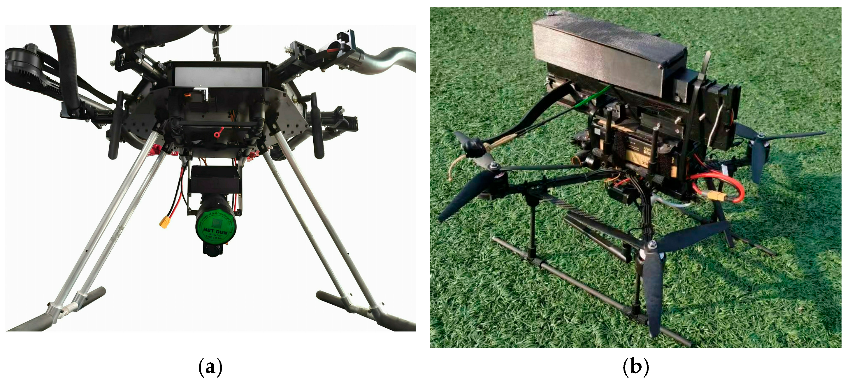
2. Establishment of a Quadrotor UAV Model with a Launch Device

In the process of establishing the mathematical model of a quadrotor UAV with a launch device, we employed the Newton–Euler method for dynamic analysis, thereby obtaining the dynamic and control equations of the UAV [1,2]. At the same time, we have also introduced the attitude angle information of the launch device relative to the airframe coordinate system, further studying the impact of firing at different attitudes on the position and posture of the UAV.

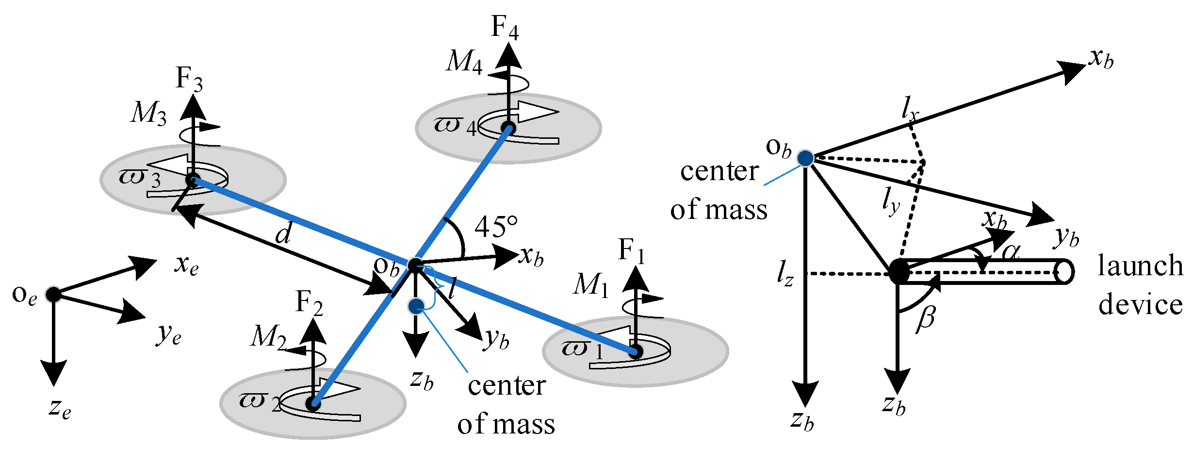
2.1. Six-DOF Dynamics Equations of Multi-Rotor UAVs

Multi-rotor UAVs can be equipped with a corresponding launch device as needed, such as crossbows [23], net guns [16], firearms [17], etc. To accurately describe the dynamic characteristics of the UAV, two coordinate systems are introduced in the text: the world coordinate system and the body coordinate system. The body coordinate system is rigidly connected to the UAV body and changes with the UAV’s attitude. The body coordinate system can be transformed into the world coordinate system through Euler angles. The world coordinate system used in the text follows the “North–East–Down” direction, denoted as x e , y e , z e , while the body coordinate system follows the “Forward–Right–Down” direction, denoted as x b , y b , z b . Both coordinate systems are right-handed coordinate systems.
The positional relationship between the launch device and the UAV is shown in Figure 1, with two scenarios: below [24] and above the UAV. The difference between these two positions is that the recoil after firing affects the attitude of the UAV, primarily the pitch angle, which in turn affects the position of the UAV. The variable η is used to distinguish between these two situations: when the launch device is located below the UAV, η = 1; when the launch device is located above the UAV, η = −1. This paper focuses on the scenario where the launch device is located below the UAV but still takes this factor into account during the model establishment process.
In the design field of quadrotor UAVs, the frame structures are mainly divided into two configurations: “X”-type and “+”-type. For the “+”-type frame, the motor mounting positions are aligned with the x b and y b axes of the vehicle coordinate system. In contrast, the motor layout of the “X”-type frame results in the diagonal lines connecting the motors forming a 45° angle with the vehicle coordinate axes x b and y b .
Considering that the “X”-type frame has become the industry standard due to its superior symmetry and wide range of applications, this paper will adopt the “X”-type frame as the basis for the analysis. The vehicle structure and coordinate system setup of the UAV are shown in Figure 2, which provides a detailed display of the geometric configuration and the corresponding relationships of the coordinate system, offering an accurate reference framework for dynamic analysis and the formulation of control strategies [3,4].
To facilitate the UAV’s targeting and striking of objectives in various directions, as shown in Figure 2, a two-axis gimbaled mount is installed on the UAV body. The launch device is connected to the body through this mount, enabling rotation about the y b and z b -axes of the vehicle coordinate system. The projection of the launch device axis in plane x b y b and x b -axis is denoted α, and the angle with the z b -axis is denoted as β. Due to the constraints of the UAV body and the mounting feet, the range of α is from −30° to 30° (positive direction is counterclockwise), and the range of β is from 0° to 120° (positive direction is counterclockwise). When the launch angle β = 0°, the launch direction aligns with the z b -axis of the body, suitable for targeting objects below the UAV; when α = 0°, targets within the x b z b plane can be struck; when α = 0° and β = 90°, targets directly in front of the UAV can be aimed; when β > 90°, targets above the UAV can be targeted.
After firing, the total mass of the UAV, including the gimbaled mount and the launch device, is m, and the acceleration due to gravity is denoted as g. In the world coordinate system, the position coordinates of the UAV’s center of mass are p = [ p x p y p z ] T , and the distance from the motors to the body’s center of mass is d. The coordinates of the desired position are p d = [ x d y d z d ] T , the UAV’s center of mass velocity is v = [ v x v y v z ] T , and the UAV’s attitude Θ = [ ϕ θ ψ ] T is represented by Euler angles, ϕ (roll), θ (pitch), and ψ (yaw). In the body coordinate system, the angular velocities around the body coordinate axes are ω = [ ω x ω y ω z ] T   , the lift force magnitude is F, the thrust provided by propellers 1 to 4 is F 1 ,   F 2 ,   F 3 ,   F 4 , respectively, and the moments about the x b , y b , z b axes are M x , M y , M z , with corresponding moments of inertia I x , I y , I z . The recoil force of the launch device is F s , with components in the three body coordinate axis directions being F s x ,   F s y ,   F s z , and the moments formed by the recoil force on the body are M s x , M s y , M s z . [ l x l y l z ] T denotes the coordinates of the firing point relative to the UAV’s center of mass in the body coordinate system.
The forces and moments exerted by the launch device on the UAV within the body coordinate system are described as follows [15,18]:
F s x F s y F s z = F s cos α sin β F s sin α sin β F s cos β ,
M s x M s y M s z = l x l y l z × F s x η F s y F s z       = l y F s z l z η F s y l z F x l x F s z l x η F s y l y F s x .
The kinematic and dynamic models of the UAV are shown as follows:
p ˙ = v ,
m v ˙ x m v ˙ y m v ˙ z = 0 0 m g R b e F s x F s y F + F s z .
In the equations, m is the mass of the UAV, g is the acceleration due to gravity, F is the resultant force of the thrust from the four propellers, with the downward direction defined as the positive direction, and R b e is the rotation matrix from the body coordinate system to the world coordinate system, expressed as follows:
R b e = R z T ( ψ ) R y T ( θ ) R x T ( ϕ ) .
In which, R x , R y , R z are defined as follows:
R x ( ϕ ) = 1 0 0 0 cos ϕ sin ϕ 0 sin ϕ cos ϕ R y ( θ ) = cos θ 0 sin θ 0 1 0 sin θ 0 cos θ R z ( ψ ) = cos ψ sin ψ 0 sin ψ cos ψ 0 0 0 1
The relationship between the UAV’s attitude rate of change and the body angular velocity is shown as follows:
ϕ ˙ θ ˙ ψ ˙ = 1 tan θ sin ϕ tan θ cos ϕ 0 cos ϕ sin ϕ 0 sin ϕ / cos θ cos ϕ / sin θ ω x ω y ω z ,
I x ω ˙ x I y ω ˙ y I z ω ˙ z = M x M y M z ω x ω y ω y ω z ω x ω z × I x I y I z + M s x M s y M s z .
The lift force and torque experienced by the UAV have a specific relationship with the thrust provided by each propeller. The rotor radius of the drone is d. The distance between the propeller’s center and the drone’s center of mass on the z e -axis is l , where l = c M / c T , c M and c T are the torque coefficient and thrust coefficient, respectively, both of which can be measured experimentally. The specific expressions for the forces and torques on the UAV are as shown as follows [1].
F = F 1 + F 2 + F 3 + F 4 M x = 2 2 d ( F 1 F 2 F 3 + F 4 ) M y = 2 2 d ( F 1 + F 2 F 3 F 4 ) M z = l ( F 1 F 2 + F 3 F 4 )
in which F i represents the lift force of the i-th propeller, where i = 1, …, 4.

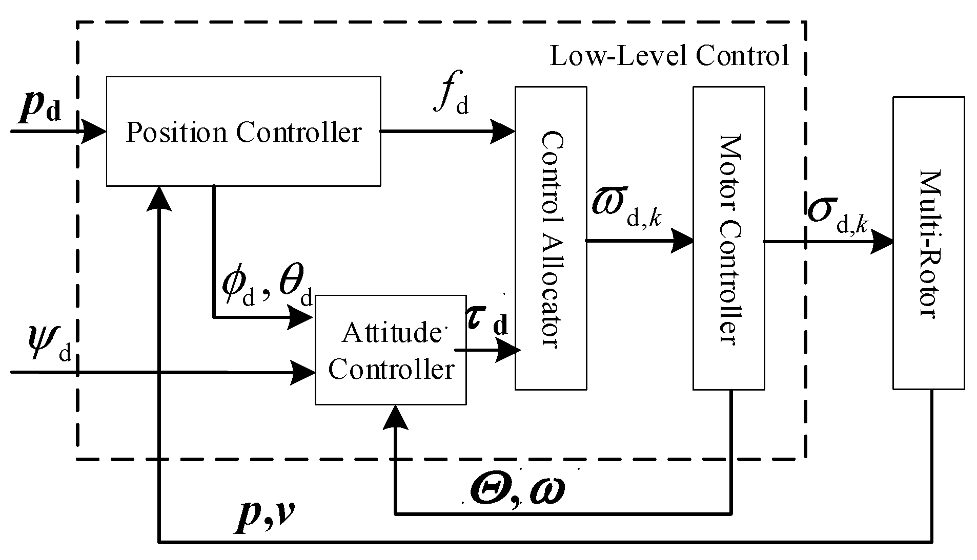
2.2. UAV Low-Level Control

The fully autonomous control closed-loop diagram of the multi-rotor UAV is shown in Figure 3, which is divided into inner-loop control and outer-loop control. The inner-loop controller is the attitude controller, and the outer-loop controller is the position controller. Both the attitude and position control of the UAV adopt a PID control strategy to achieve point control. The PID parameters are obtained using the MATLAB “PID Autotuning for UAV Quadcopter” module [25], and these parameters do not consider the disturbance of the recoil force from the launch device. Detailed PID parameters can be found in Table 1. Since the quadrotor UAV is an underactuated system [17,18,19,20], it can only control four independent variables. To facilitate aiming, the four controlled variables include three desired position coordinates p d and one desired yaw angle ψ d . The actual position coordinates of the UAV are p , and the error between the desired position and the actual position is represented as p e = [ x e y e z e ] T ; the actual attitude Euler angles of the UAV are Θ , and the error between the desired attitude angles and the actual attitude angles is represented as Θ e = [ ϕ e θ e ψ e ] T .
Firstly, through the position control loop, using the desired position coordinates p d in conjunction with the PID control algorithm, the control inputs U 1 , U x , U y can be calculated. Subsequently, the desired Euler angles ϕ d , θ d are calculated using the desired horizontal position coordinates x d , y d . The specific calculation method for the entire process is shown as follows:
x e = x d p x y e = y d p y z e = z d p z
U 1 = k p z p z e + k p z i 0 t z e d t + k p z d z ˙ e U x = k p x p x e + k p x i 0 t x e d t + k p x d x ˙ e U y = k p y p y e + k p y i 0 t y e d t + k p y d y ˙ e
ϕ d θ d = 1 ( F + F s z ) sin ψ cos ψ cos ψ sin ψ U x F s x U y F s y .
PID related parameter descriptions are provided in Table 1.
Through the attitude control loop, based on the desired Euler angles ϕ d and θ d calculated by the position control loop, and combining with the given desired yaw angle ψ d , the errors between the desired attitude angles and the actual attitude angles of the UAV can be determined as follows
ϕ e = ϕ d ϕ θ e = θ d θ ψ e = ψ d ψ
Using these error values, along with the PID control algorithm, the control inputs U 2 , U 3 , U 4 can be further calculated.
U 1 = F U 2 = M x = k ϕ p ϕ e + k ϕ i 0 t ϕ e d t + k ϕ d ϕ ˙ e U 3 = M y = k θ p θ e + k θ i 0 t θ e d t + k θ d θ ˙ e U 4 = M z = k ψ p ψ e + k ψ i 0 t ψ e d t + k ψ d ψ ˙ e
The output values U 1 , U 2 , U 3 , U 4 can be used as the basis for controlling the lift force F and the moments M x , M y , M z , along with the recoil force F s as input parameters substituted into dynamic Equations (3)–(9). Through the calculations of these equations, the real-time position and attitude of the UAV, p and Θ , can be obtained. Utilizing these equations allows for the determination of the real-time position and attitude of the quadrotor UAV when affected by the recoil force.

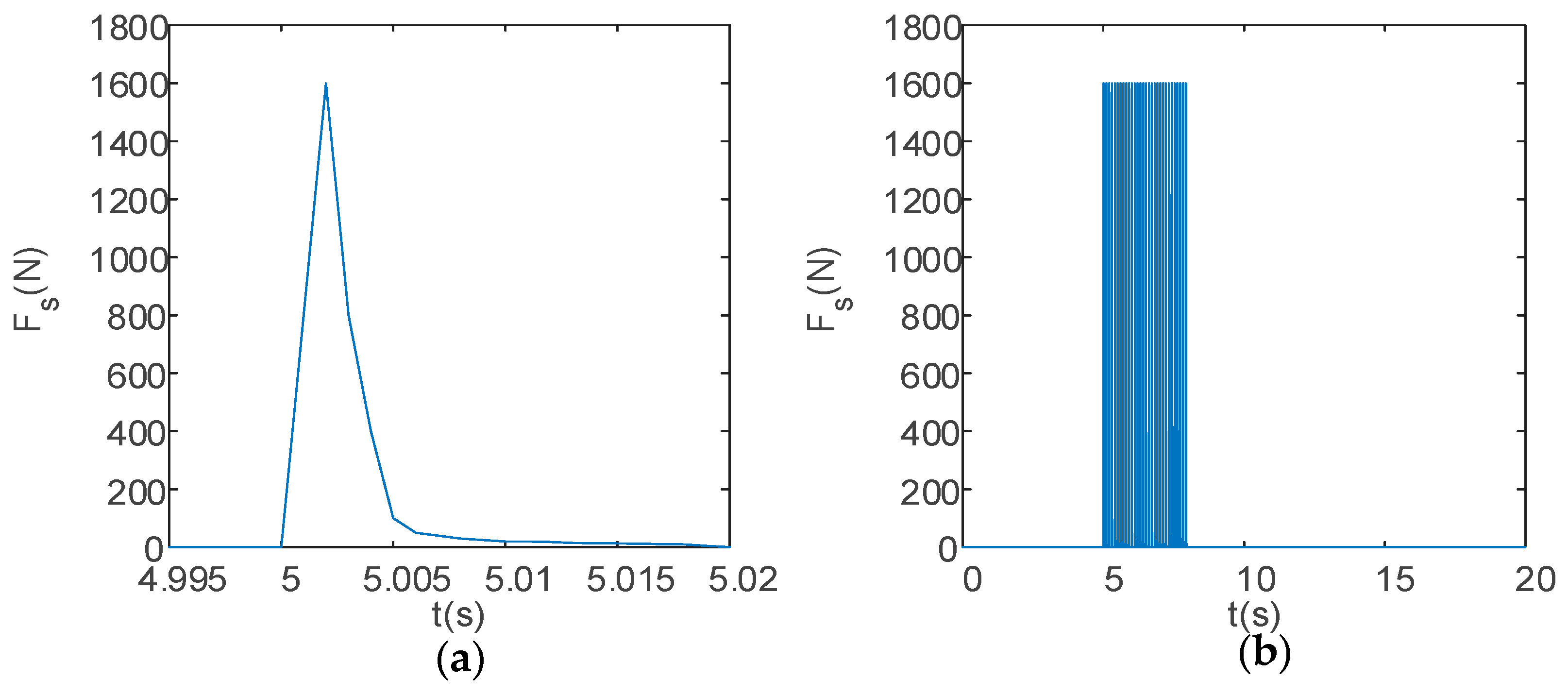
2.3. Ballistic Equations of the Launch Device

If it can be considered that the direction of the firing point is the same as the direction of the recoil force, then the position of the UAV’s firing point [ p l x p l y p l z ] T can be calculated.
p l x p l y p l z = R b e l x l y l z + p x p y p z .
In the global coordinate system, the initial direction of the projectile -(for ease of description, this paper collectively refers to the objects launched by the launch device as projectiles, including arrows, crossbow bolts, bullets, shotgun shells, capture nets, etc.) -when fired can be represented using [ K x K y K z ] T .
K x K y K z = R b e cos α sin β sin α sin β cos β .
To facilitate the analysis of the projectile’s point of impact accuracy, we have simplified the analysis by neglecting the effect of gravity on the projectile, which is reasonable for projectiles with high initial velocities when conducting short-range accuracy analysis [26,27]. Therefore, we assume the trajectory of the projectile from the launch device to be a straight line, and the point of impact at x e is given as follows:
y e = K y ( x e p l , x ) K x + p l , y z e = K z ( x e p l , x ) K x + p l , z
When the x-coordinate of the desired point is equal to x e , we can determine that the point of impact lies on the plane where x e = x .

2.4. Model Assumptions

For the sake of computational simplicity, the following assumptions are made:
  • The weight of the UAV remains constant after firing;
  • During firing, the entire UAV, gimbaled mount, and payload are considered as a single rigid body;
  • The motion of the UAV is not affected by other disturbances;
  • The effects of the Earth’s rotation and revolution are neglected;
  • The safe range of UAV attitude angle changes is limited to between 0° and 55°;
  • Within the safe range of UAV attitude angle changes, the effect of air resistance is ignored;
  • Due to the short shooting distance, the projectile’s trajectory is assumed to be a straight line, and the projectile’s initial velocity direction is consistent with the aiming and firing direction, unaffected by the UAV body and gimbaled mount.

2.5. Input Parameter Settings

The parameter settings for the UAV are detailed in Table 1. The table lists the following parameters of the UAV: inherent physical parameters, initial state parameters, initial input parameters, output limit range parameters, and set parameters.
The total calculation time for the entire motion process of the UAV is set to 20 s. The desired height of the UAV is set to 5 m. At 5 s into the flight, the launch device begins firing. The variation in the recoil force Fs experienced by the launch device over time is detailed in Table 2 and shown in Figure 4 and Figure 5: when the UAV fires a large payload in a single shot, these data simulate the scenario of firing a rocket projectile or a capture net, with a total impulse of 13.53 N·s (see Figure 4); when the UAV fires a small payload in a burst, the total impulse per shot is 3.983 N·s, and the total impulse for 30 shots in a burst is 119.49 N·s (see Figure 5).

3. Analysis of UAV Single-Shot Firing with Heavy Payload

This section begins by analyzing, through simulation, the impact of the two-axis gimbaled platform connecting the UAV and the launch device on the UAV’s attitude and torque changes during heavy-load single-shot firing at various orientations. Subsequently, the analysis examines the effects of firing on the UAV’s position and lift force.

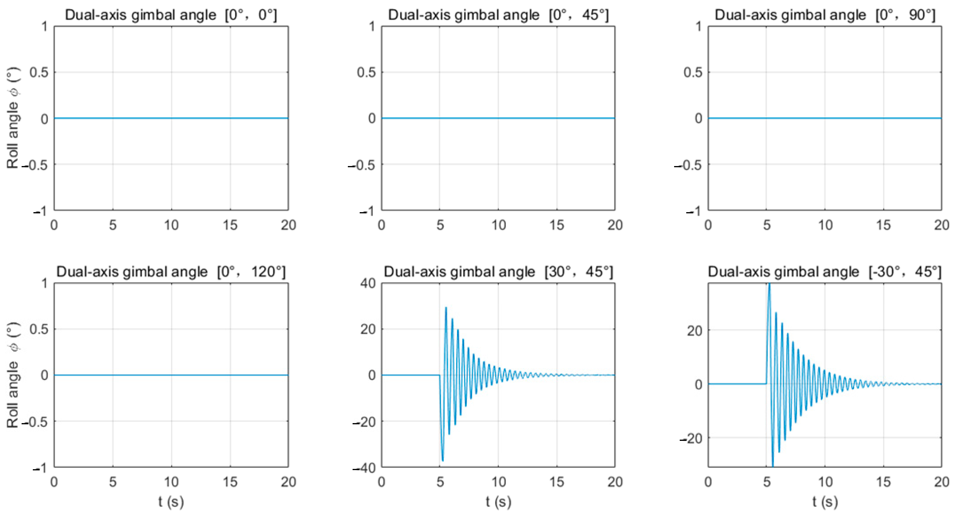
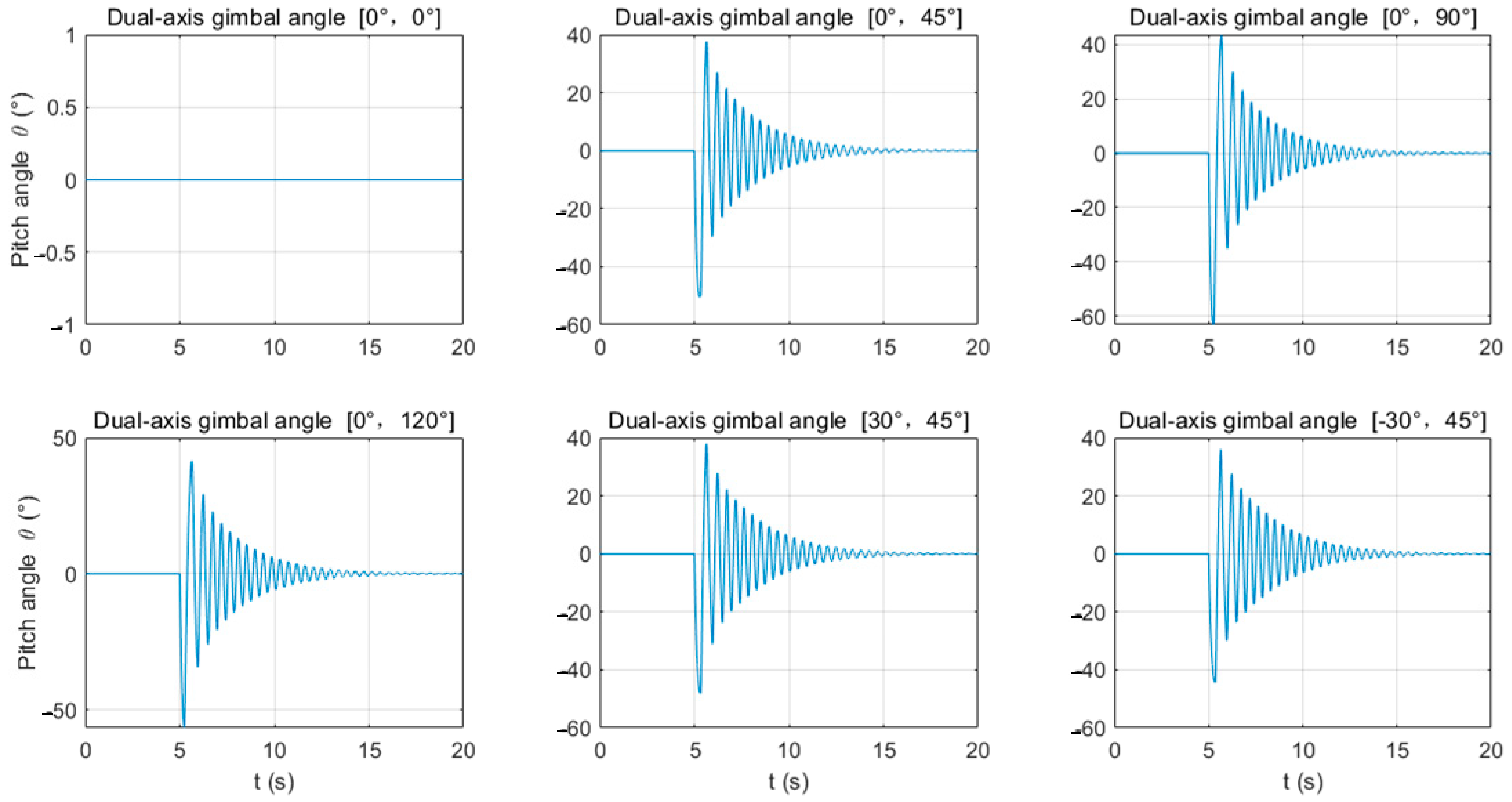
3.1. Patterns of UAV Attitude and Torque Changes During Single-Shot Firing

In the MATLAB Simulink environment, a nonlinear model of the quadrotor UAV and a recoil model of the launch device are constructed [28]. The recoil force of the launch device is used as a disturbance input to the UAV’s six-degree-of-freedom motion module. The UAV uses a PID controller to perform closed-loop control on its position and attitude based on the given desired positions and heading angles. Calculations reveal that when the z b -axis gimbaled mount remains stationary (i.e., α = 0°) and fires forward, as shown in Figure 6 and Figure 7, the roll angle ϕ and yaw angle ψ do not change, and the UAV’s control torques M x and M z are also 0. However, when the z b -axis gimbaled mount rotates for lateral firing (i.e., α ≠ 0°, β ≠ 0°), the roll angle ϕ and yaw angle ψ will need to be adjusted. In particular, when the z b -axis gimbaled mount fires in the opposite direction (α is 30° and −30°, respectively), the adjustment directions of the roll angle ϕ and yaw angle ψ are also opposite.
As can be seen from Figure 6 and Figure 7, and Table 3, when the z b -axis gimbaled mount rotates for lateral firing (α ≠ 0°, β ≠ 0°), the range of motion of the roll angle ϕ is greater than that of the yaw angle ψ (for example, when α = 30° and β = 45°, the variation range of ψ can reach 37.37°, while the variation range of ψ does not exceed 9.22°). Correspondingly, the UAV’s control torque M x is also greater than M z .
As shown in Figure 8 and Table 3, except for firing vertically towards the ground (gimbal firing angle α = 0°, β = 0°), when firing at any other angle, the UAV’s pitch angle θ will change, as will the UAV’s control torque M y . Under the influence of the recoil force, the pitch angle θ is initially negative, with its maximum and minimum values having a small difference in magnitude. When firing in the horizontal direction (α = 0°, β = 90°), the pitch angle’s range of change is the greatest (θmin = −63.089°, θmax = 43.614°). This is due to the maximum torque exerted on the pitch angle by the recoil force. At this point, the attitude angle exceeds 55°, and the UAV may crash due to excessive attitude. It is recommended that the UAV should fire downwards (β < 90°).

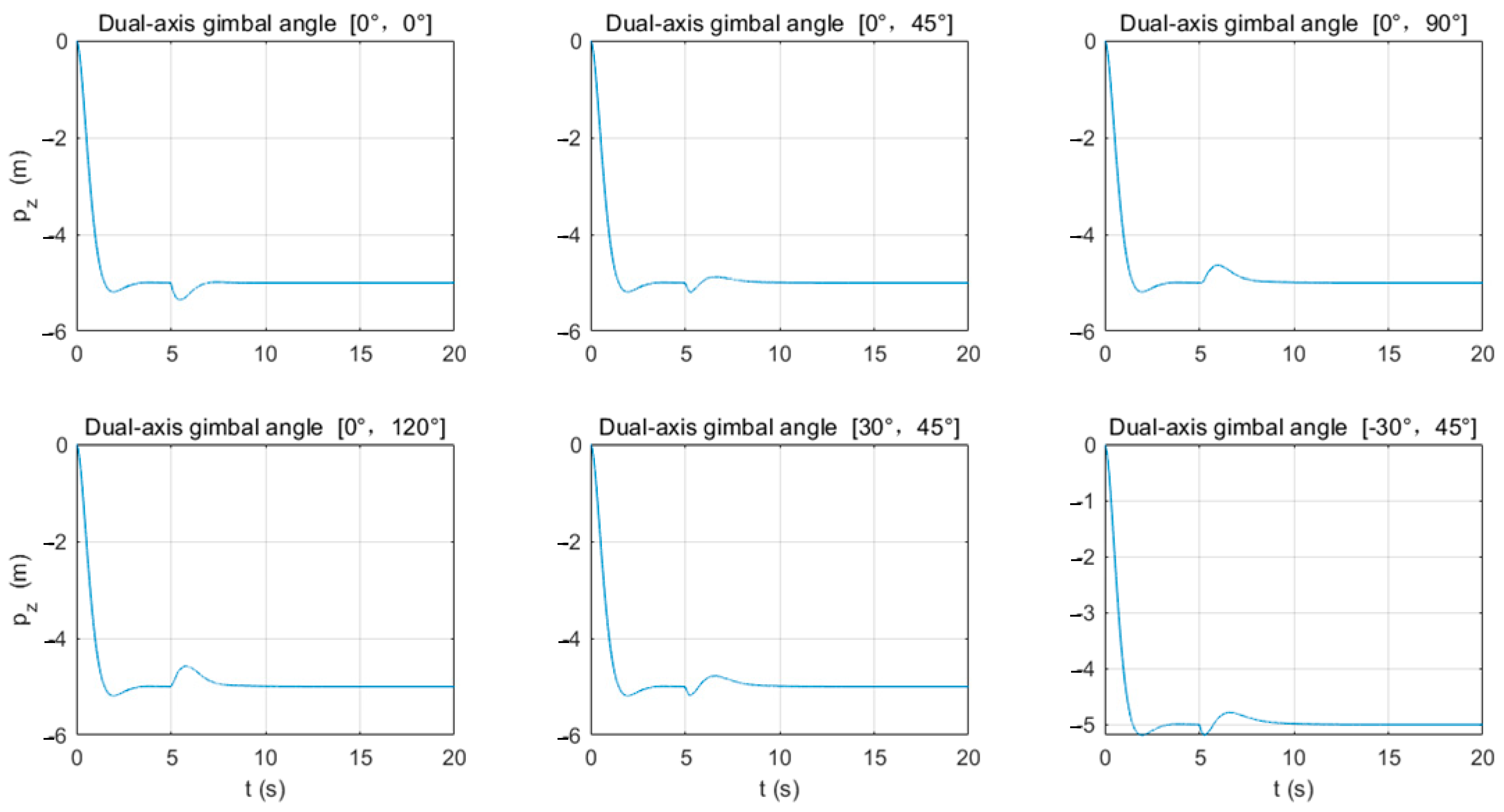
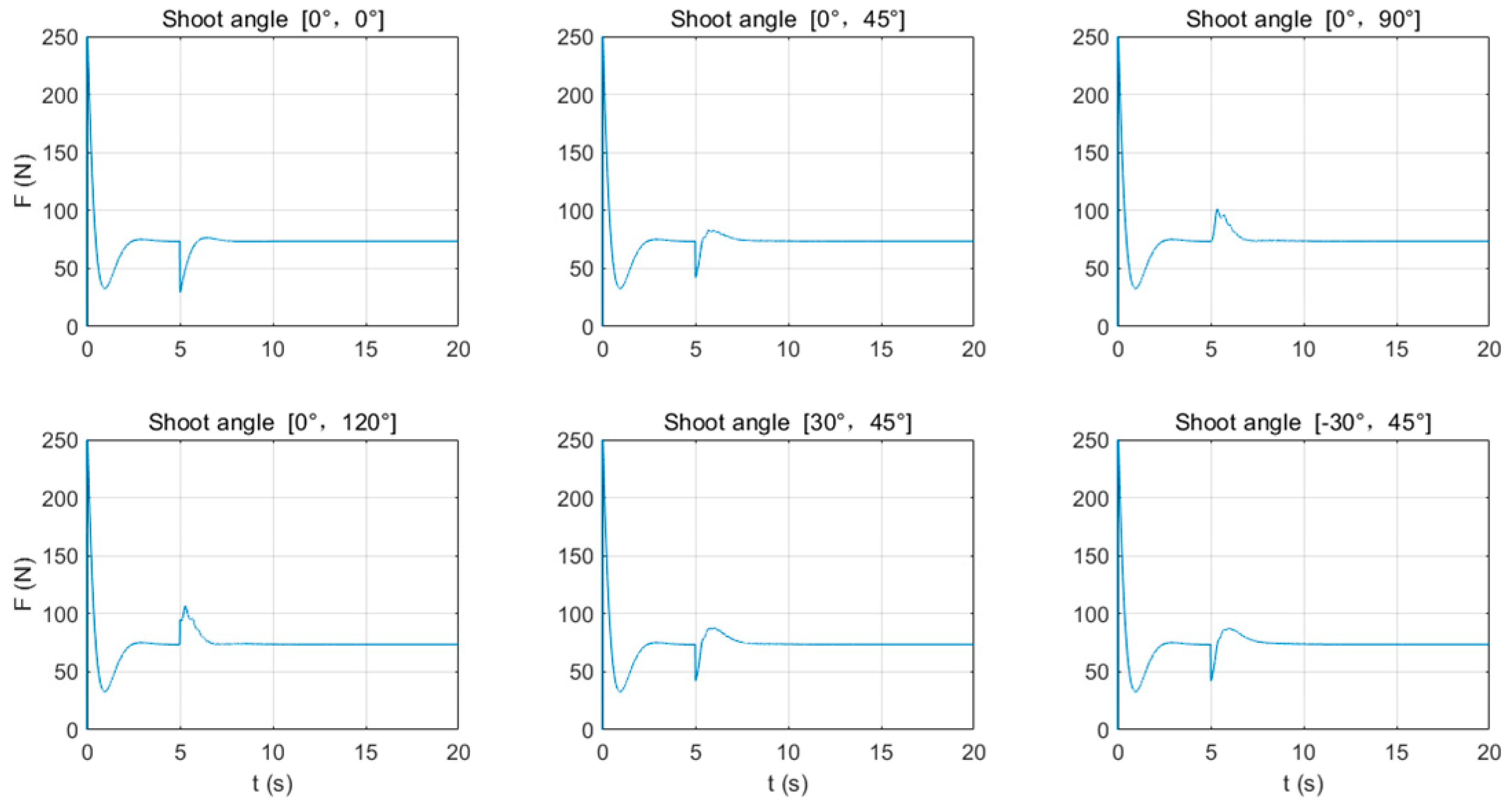
3.2. UAV Position and Lift Force Change Patterns

From Figure 9, it can be observed that when the gimbaled mount rotates around the y b -axis and fires in the positive direction of the x e -axis, except for the case of firing straight down (i.e., β = 0°), in other cases, the UAV will initially move in the negative direction of the x e -axis under the influence of the recoil force and then gradually adjust to a balanced position. Particularly when the gimbaled mount on the y b -axis is rotated to a larger angle (β > 45°) for firing, the UAV will first move in the negative direction of the x e -axis and then adjust to the positive direction of the x e -axis. According to the data in Table 4, as the rotation angle of the gimbaled mount on the y b -axis increases, the distance the UAV moves in the positive direction of the x e -axis also increases. For example, when the rotation angle of the gimbaled mount is α = 0°, β = 120°, the UAV moves almost entirely in the positive direction of the x e -axis by 0.129 m.
From Figure 10, it can be seen that when the gimbaled mount on the z b -axis rotates for firing ( ≠ 0°), lateral displacement occurs under the influence of the recoil force, with the displacement direction being opposite to the firing direction.
From Figure 11 and Figure 12, it can be observed that when the gimbaled mount rotates around the y b -axis and fires in the direction of the ground (β ≤ 45°), the lift force F required by the UAV decreases, causing the UAV to rise and move in the direction of the sky (negative direction of the z e -axis), while when β > 45°, the lift force required by the UAV increases. According to the data in Table 4, when α = 0°, β = 0°, Fmax = 76.452 N; when α = 0°, β = 120°, Fmax = 106.787 N. In this case, the UAV’s height above the ground decreases, moving in the direction of the ground (positive direction of the z e -axis).
It is known from Table 4 that when the rotation angle β of the gimbaled mount on the y b -axis remains constant, the lift force required also increases with the rotation angle α of the gimbaled mount on the z b -axis. For example, when α = 0°, β = 45°, Fmax = 83.141 N, and when α = 30°, β = 45°, Fmax = 87.744 N. Therefore, when determining the lift force parameters of the UAV, it should be set according to the maximum rotation angles (αmax, βmax).
Unlike the movement of a ground-based launch device after firing, the UAV, in most cases after firing, experiences greater changes in the vertical direction than in the horizontal direction. For example, when firing straight down, the UAV’s upward movement can reach 0.353 m, while when the firing angle is α = 0°, β = 120°, the UAV descends by 0.428 m compared to a maximum horizontal change of only 0.211 m.
This difference is due to the change in the UAV’s attitude angles caused by the recoil force during firing, leading to a change in the direction of the lift force. In the vertical direction, the recoil force disrupts the original equilibrium, while in the horizontal direction, the component of the lift force is opposite to the direction of the recoil force, which can offset part of the recoil force, resulting in less horizontal displacement. Therefore, it is necessary to ensure that there are no obstacles around after firing, especially to pay attention to safety in the vertical direction.
It can also be observed that when the launch device fires downward (β = 45°), compared to lateral firing (α = ±30°), the change in attitude angles is smaller. Therefore, lateral downward firing during single-shot firing helps to reduce the change in the UAV’s attitude angles. Using gimbaled angles of α = 30° and β = 45° can reduce the movement amplitude of the UAV’s attitude and position, thereby reducing the risk of the UAV crashing or colliding.

4. Analysis of UAV Burst Firing with Light Payload

In this section, we first analyze the impact of the two-axis gimbaled platform connecting the UAV and the launch device on the UAV’s attitude and torque changes during low-load rapid firing through simulation. Subsequently, we discuss the effects of firing on the UAV’s position and lift force. Finally, we investigate the accuracy of continuous firing at a fixed distance.

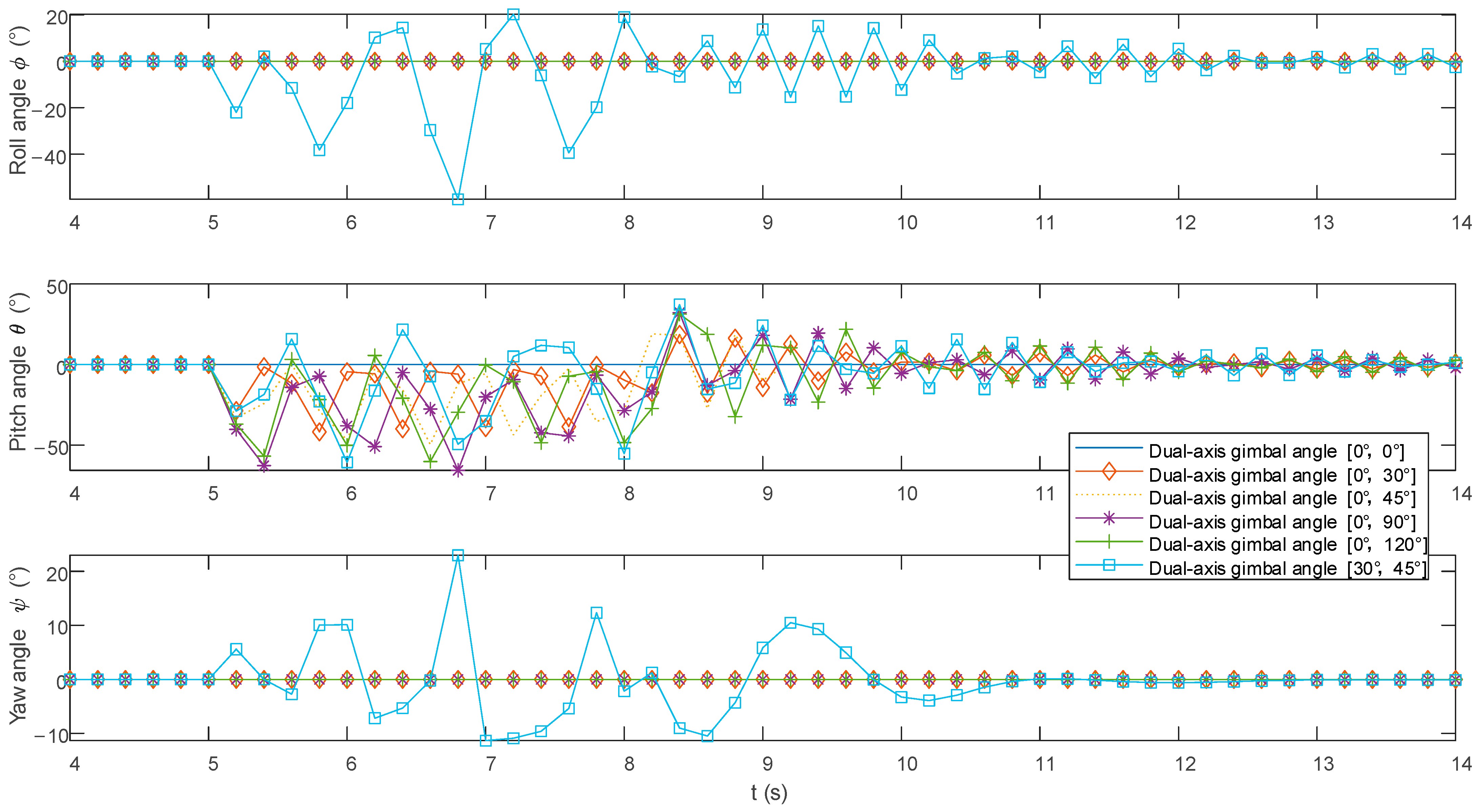
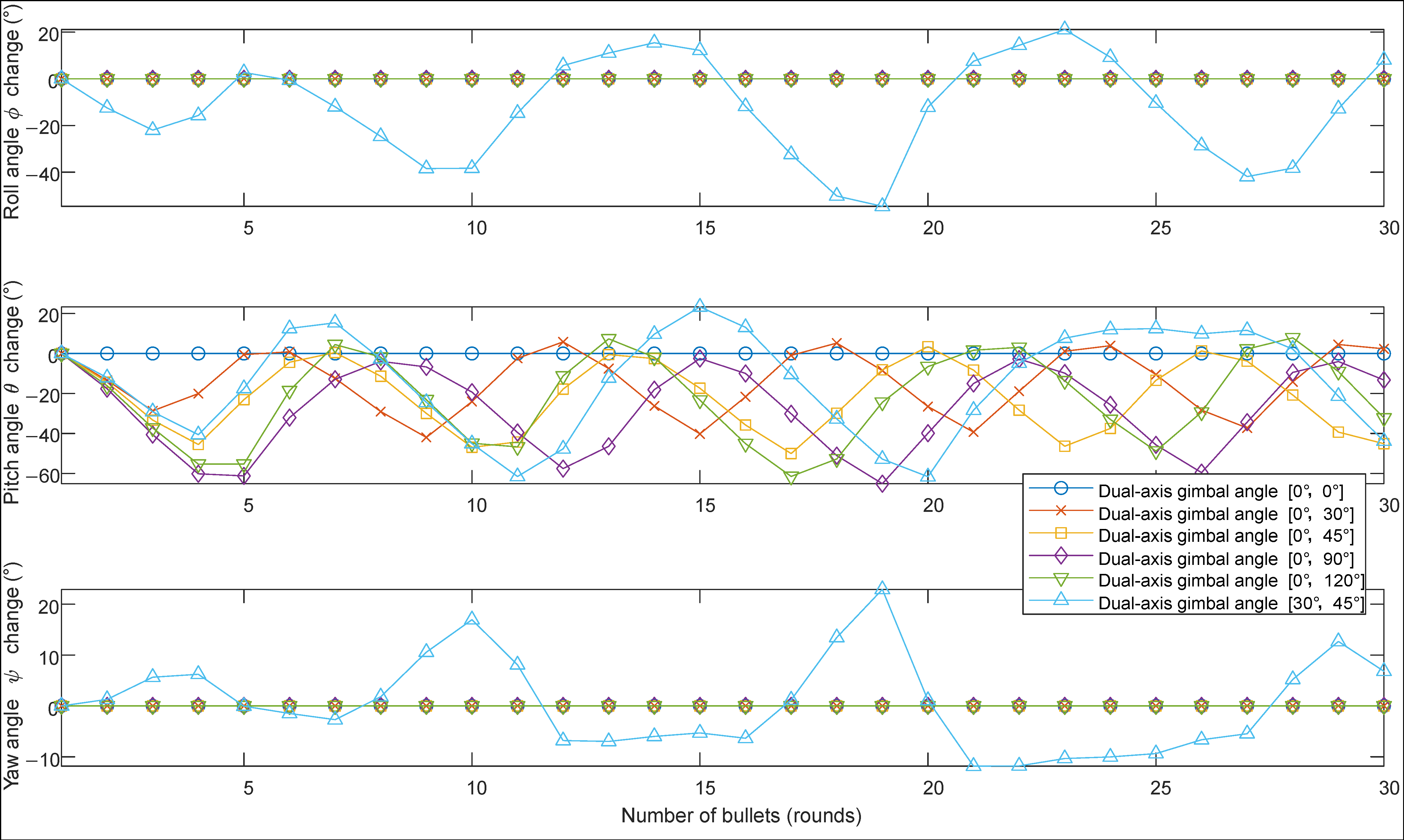
4.1. Patterns of UAV Attitude and Torque Changes During Burst Firing

The UAV fires 30 rounds of ammunition at the 5th second and ceases firing at the 8th second. Figure 13 illustrates the relationship between the UAV’s attitude and time during the 30 round burst, where the horizontal axis represents time and the vertical axis represents the UAV’s three attitude angles. Figure 14 shows the UAV’s attitude during the 5th to 8th second burst firing, with the horizontal axis indicating the round number (1–30) and the vertical axis indicating the UAV’s attitude angle at that time. Table 5 lists the maximum and minimum values of the UAV’s attitude angles from 0 to 20 s and the maximum and minimum values of the UAV’s attitude angles during the 5–8 s ammunition firing. In the table, a negative sign indicates the opposite direction of a positive sign.
From Figure 13, it can be seen that when the z b -axis gimbaled angle is α = 0° and firing is carried out in the forward direction, there will be no change in the roll angle ϕ and yaw angle ψ. Adjustments to the roll angle ϕ and yaw angle ψ only occur when the z b -axis gimbaled mount is rotated for lateral firing (α ≠ 0° and β ≠ 0°).
For the roll angle ϕ, no change occurs during forward firing. However, during lateral firing, influenced by the recoil force, the roll angle exhibits significant fluctuations near ϕ = 0° during the launch process (5–8 s) but eventually stabilizes.
For the pitch angle θ, among the three attitude angles, it has the largest range of variation. During the firing process (5–8 s), regardless of forward or lateral firing, the pitch angle fluctuates around θ = −25°. After the drone completes a burst of fire (8–20 s), the pitch angle fluctuates around θ = 0° and then gradually adjusts back to the initial attitude (θ = 0°). Throughout the entire process (0–20 s), according to Table 5, when α = 0°, β = 30°, (θmin, θmax) = (−42.07°, 19.9°); when α = 0°, β = 90°, (θmin, θmax) = (−70.08°, 33.02°). It can be observed that the closer the y b -axis gimbal angle β is to 90°, the greater the fluctuation amplitude of the drone. When the firing angles are α = 0°, β = 90° and α = 0°, β = 120°, the absolute value of the pitch angle θ exceeds 55°, surpassing the UAV’s limited attitude angle, making the UAV prone to crashing. When β = 45°, for forward firing (α = 0°), (θmin, θmax) = (−52.34°, 33.54°), while for lateral firing (α = 30°), (θmin, θmax) = (−67.25°, 37.15°). It is evident that the pitch angle θ fluctuates more during lateral firing than during forward firing, with the absolute value exceeding 55°, making the UAV prone to crashing.
For the yaw angle ψ, no change occurs during forward firing, and during lateral firing, the yaw angle oscillates around the initial attitude (ψ = 0°).
From Table 5 and Table 6, it can also be observed that the maximum absolute values of the three attitude angles and three position changes in the UAV during the burst firing (5–8 s) are essentially consistent with the maximum absolute values throughout the entire process (0–20 s). That is, when the UAV’s attitude angles and positions are at their maximum absolute values, the UAV is firing or has just finished firing, and due to inertia, the position and attitude angles will continue to increase slightly.

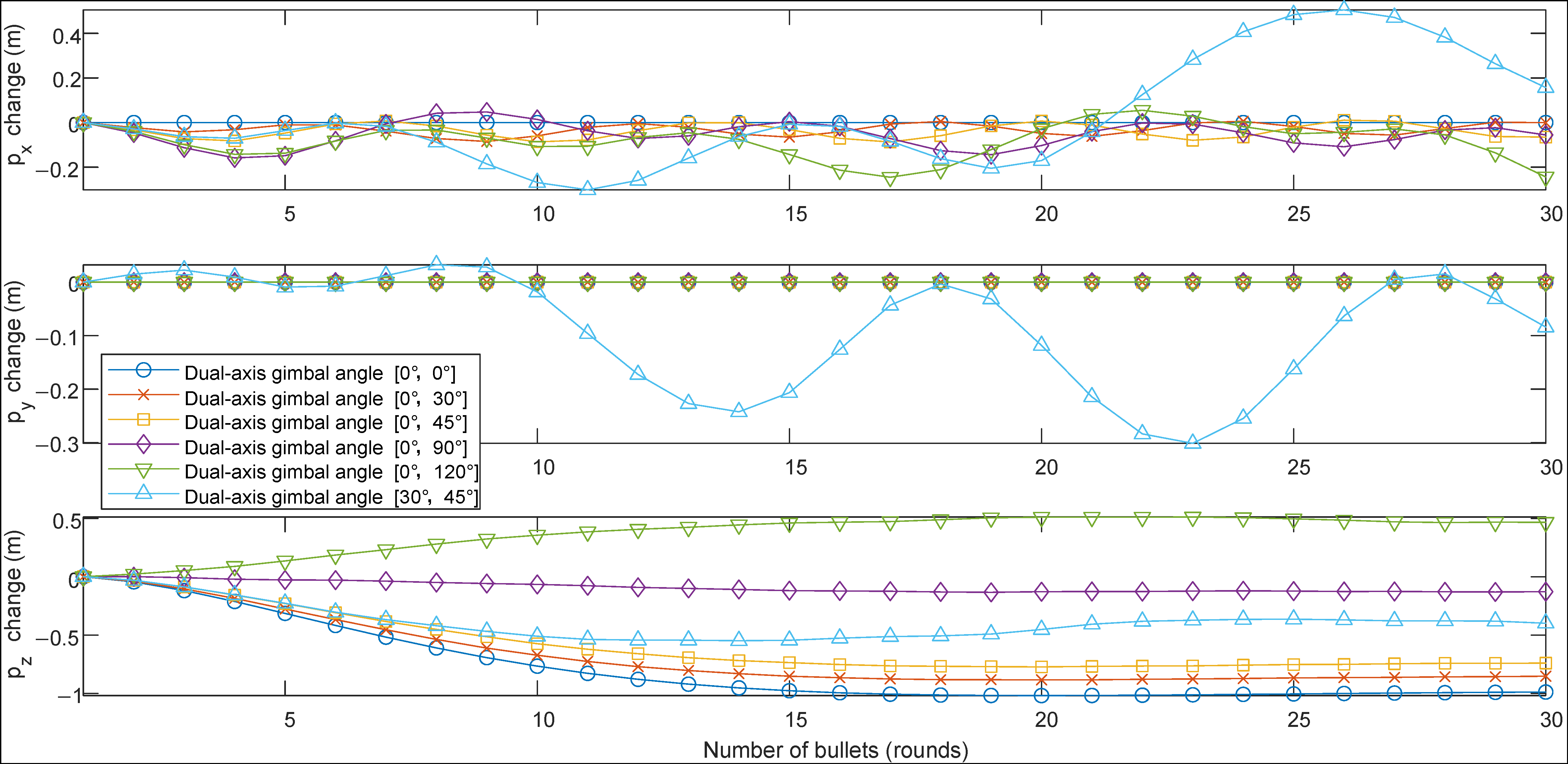
4.2. Patterns of UAV Position and Lift Force Changes

Figure 15 illustrates the relationship between the UAV’s position and time over 0–20 s, where the horizontal axis represents time and the vertical axis represents the UAV’s displacement in three directions. Figure 16 shows the position of the UAV during the firing of 30 rounds between the 5th and 8th seconds, with the horizontal axis representing the round number (1–30) and the vertical axis representing the UAV’s position at the time of firing. Table 6 lists the maximum and minimum values of the UAV’s position changes over 0–20 s, as well as the maximum and minimum values during the 5–8 s of projectile firing, with negative signs indicating the opposite direction.
From Figure 15, it can be observed that when the z b -axis gimbaled angle α is 0° and firing is carried out in the forward direction, the UAV’s center of mass only experiences displacement in the vertical z e and horizontal x e directions. When the z b -axis gimbaled mount is rotated for lateral firing (α ≠ 0°, β ≠ 0°), it causes displacement in the x b , y b , z b directions.
For the horizontal x e direction, during the firing process (5–8 s), under the influence of the recoil force, the UAV’s center of mass fluctuates around p x ≈ −0.1 m from the initial position ( p x = 0 m). After the firing is completed at the 8th second, the UAV’s position in the x e direction fluctuates around p x ≈ 0 m and tends to stabilize. Specifically, between 5 and 8 s, according to Table 6, when α = 0°, β = 30°, there are p x (min, max) = (−0.085, 0.006) m; when α = 0°, β = 120°, there are p x (min, max) = (−0.245, 0.055) m, which is 3.3 times the former. It can be seen that the larger the y b -axis gimbaled firing angle β, the greater the fluctuation amplitude of the UAV in the x e direction, mainly in the negative direction of the x e -axis, and the farther the fluctuation center value is from p x = 0 m. When β = 45°, for forward firing (α = 0°), p x (min, max) = (−0.0873, 0.011) m; for lateral firing (α = 30°), p x (min, max) = (−0.302, 0.505) m, which is 8.2 times the former. It can be seen that the UAV’s position fluctuation amplitude in the x e direction is greater during lateral firing than during forward firing.
For the horizontal y e direction, forward firing does not produce changes, but during lateral firing, the position in the y e direction continuously increases. When α = 30°, β = 45°, p y (min, max) = (0, 1.501) m; at this time, the absolute value of the coordinate change in the y e direction exceeds 1 m, and the UAV is prone to crash by touching other obstacles.
For the vertical z e direction, during the firing process (5–8 s), under the influence of the recoil force, the UAV will rise or fall from the initial position ( p z = −5 m) and tend to stabilize. After the firing is completed at the 8th second, the UAV’s center of mass in the z e direction will return to p z = −5 m and tend to stabilize. Specifically, according to Table 6, when α = 0°, β = 0°, there are p z + 5 (min, max) = (−1.019, 0.001) m; when α = 0°, β = 90°, there are p z + 5 (min, max) = (−0.133, 0.001) m. It can be seen that when the y b -axis gimbaled firing angle β is within the range of (0°, 90°), the UAV’s center of mass will rise under the influence of the recoil force, and the smaller β is, the greater the rise amplitude in the height direction. When α = 0°, β = 0°, the absolute value of the coordinate change in the y e direction exceeds 1 m, and the UAV is prone to crash by touching other obstacles.
Similarly, it can be known that when the y b -axis gimbaled angle β is within the range of (90°, 120°), between 5 and 8 s, the UAV’s center of mass will fall under the influence of the recoil force, and the greater the value of β is, the greater the fall amplitude in the height direction. When β = 45°, for forward firing (α = 0°), p z + 5 (min, max) = (−0.773, 0.001) m; for lateral firing (α = 30°), p z + 5 (min, max) = (−0.548, 0.001) m. It can be seen that the UAV’s rise amplitude in the height direction is slightly smaller during lateral firing than during forward firing.
Under the given parameters, whether forward or lateral firing, when firing 15 rounds, the UAV tends to stabilize, with almost no fluctuations, achieving dynamic balance.

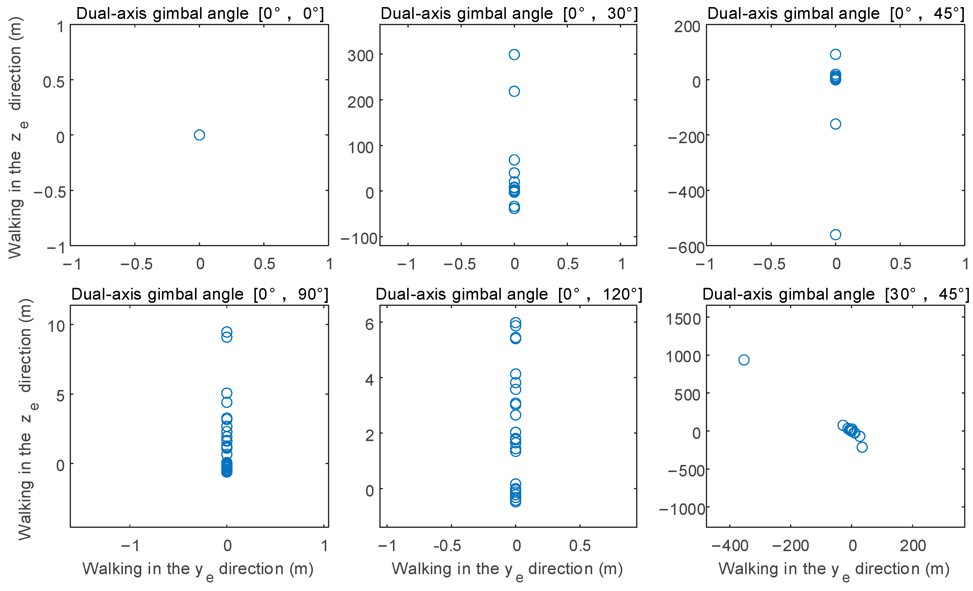
4.3. Strike Accuracy at a Fixed Distance

For the target located at x e = 5 m, when the projectile firing interval is 0.1 s, at different shooting angle conditions, the positional differences between the 30th shot and the 1st shot in the y e and z e directions are shown in Figure 17. It can be observed from the figure that lateral shooting produces errors in both the y e and z e directions; vertical downward shooting has the highest precision. When shooting at angles from 0° to 90° and 0° to 120°, the dispersion is within 10 m, while dispersion from other angles exceeds 100 m.
When the shooting interval is extended from 0.1 s to 1 s and 2 s, Figure 18 and Table 7 illustrate the positional difference between the 30th shot and the 1st shot in the z e direction (shooting errors exceeding 50 m are considered meaningless and thus not displayed in Figure 18). The charts show that when the shooting interval is extended to 1 s, the maximum dispersion in the z e direction for shots taken in various attitudes is less than 10 m; when the shooting interval is extended to 2 s, the maximum dispersion in the z e direction for shots taken in various attitudes is less than 5 m. Under different shooting intervals, the dispersion effect is optimal when the shooting angles are between 0° and 90° and between 0° and 120°.

5. Conclusions

This study, focusing on the “X”-type quadrotor UAV equipped with a two-degree-of-freedom gimbaled launch device, established dynamic models, control models, and ballistic models to analyze the impact of firing actions on the UAV’s flight status and the probability of hitting the target. The main findings are as follows:
  • Whether it is single-shot or continuous firing, the recoil torque after firing causes significant changes in the UAV’s pitch angle, which fluctuates during shooting. When firing horizontally, the firing torque is the greatest and may exceed the allowed angle of the UAV, leading to a crash. Therefore, this angle is suitable for smaller launch loads. For larger loads, it is recommended to fire downwards to reduce the amplitude of attitude changes. At the same time, changes in the UAV’s attitude angles during firing will cause changes in the direction of lift force, leading to greater vertical position changes than horizontal ones. Attention should be paid to the altitude direction after firing to avoid collisions with obstacles.
  • When firing a large payload in a single shot, the analysis of six different launch angles revealed that the precision is highest when firing vertically downward (gimbal angles α = 0°, β = 0°), which can be used for counter-UAV purposes. Firing a capture net at a target UAV from above can effectively hit the target. When firing laterally downward (gimbal angles α = 30°, β = 45°), the torque is minimized, and the UAV’s attitude and position changes after firing can be effectively reduced.
  • When the UAV fires a small payload in a burst, vertical downward firing also has the highest precision. In open areas, if the UAV’s maneuvering speed is fast, or the target is slow, a downward attack can be adopted. Unlike single-shot firing, the error in lateral firing during burst firing is larger, and it is not recommended. If the UAV needs to improve the precision of burst firing without a gimbaled mount, for targets ahead, the firing device can be installed at angles α = 0°, β = 90°; for targets in a narrow working area below, the firing device can be installed at angles α = 0°, β = 45°. Finally, controlling the burst interval is a key factor in controlling precision. When the interval between bursts is too short, precision is poor; if it is too long, firepower is weak. The optimal firing angles corresponding to different burst intervals are different and require specific calculations.
Future research can further explore the dynamic response of UAVs under different firing conditions, as well as more advanced control strategies, to improve the performance and reliability of UAVs in practical applications.

Author Contributions

Conceptualization, Y.H.; methodology, Y.H., H.X., W.L. and S.C.; software, Y.H. and L.D.; validation, Y.H., H.X. and L.D.; writing—original draft preparation, Y.H.; writing—review and editing, L.D.; supervision, W.Z.; project administration, W.Z. All authors have read and agreed to the published version of the manuscript.

Funding

This research received no external funding.

Data Availability Statement

The original contributions presented in this study are included in the article. Further inquiries can be directed to the corresponding author(s).

DURC Statement

Current research is limited to the field of aerospace engineering and autonomous systems, specifically the development and analysis of a precision launch device mounted on quadrotor UAVs for countering intruding drones. This research is beneficial for enhancing security measures against unauthorized aerial intrusions, which is crucial for protecting critical infrastructure and public safety, and ensuring that a threat is not posed to public health or national security. The authors acknowledge the dual-use potential of the research involving the development and analysis of a quadrotor UAV-mounted launch device and confirm that all the necessary precautions have been taken to prevent potential misuse. As part of our ethical responsibility, the authors strictly adhere to relevant national and international laws regarding DURC. We advocate for responsible deployment, ethical considerations, regulatory compliance, and transparent reporting to mitigate misuse risks and foster beneficial outcomes.

Conflicts of Interest

The authors declare no conflicts of interest.

References

  1. Quan, Q. Design and Control of Multi-Rotor Aircraft; Publishing House of Electronics Industry: Beijing, China, 2018; pp. 57–89. [Google Scholar]
  2. Kim, J.; Gadsden, S.A.; Wilkerson, S.A. A Comprehensive Survey of Control Strategies for Autonomous Quadrotors. Can. J. Electr. Comput. Eng. 2020, 43, 3–16. [Google Scholar] [CrossRef]
  3. Beard, R.W. Quadrotor Dynamics and Control. Brigh. Young Univ. J. 2008, 19, 46–56. [Google Scholar]
  4. Sabatino, F. Quadrotor Control: Modeling, Nonlinear Control Design, and Simulation. Master’s Thesis, KTH Electrical Engineering, Stockholm, Sweden, 2015; pp. 12–29. [Google Scholar]
  5. Roldán-Gómez, J.J.; González-Gironda, E.; Barrientos, A. A Survey on Robotic Technologies for Forest Firefighting: Applying Drone Swarms to Improve Firefighters’ Efficiency and Safety. Appl. Sci. 2021, 11, 363. [Google Scholar] [CrossRef]
  6. Yuan, C.; Liu, Z.; Zhang, Y. Fire Detection Using Infrared Images for UAV-Based Forest Fire Surveillance. In Proceedings of the 2017 International Conference on Unmanned Aircraft Systems (ICUAS), Miami, FL, USA, 13–16 June 2017; pp. 567–572. [Google Scholar]
  7. Kunertova, D. The War in Ukraine Shows the Game-Changing Effect of Drones Depends on the Game. Bull. Atmos. Sci. 2023, 79, 95–102. [Google Scholar] [CrossRef]
  8. Wang, J.; Liu, Y.; Song, H. Counter-unmanned aircraft systems (C-UAS): State of the art, challenges, and future trends. IEEE Aerosp. Electron. Syst. Mag. 2021, 36, 4–29. [Google Scholar] [CrossRef]
  9. Nichols, R.K.; Mumm, H.C.; Lonstein, W.D.; Ryan, J.J.; Carter, C.; Hood, J.P. Counter Unmanned Aircraft Systems Technologies and Operations; New Prairie Press: Manhattan, KS, USA, 2020. [Google Scholar]
  10. Valente, J.; Sari, B.; Kooistra, L.; Kramer, H.; Mücher, S. Automated Crop Plant Counting from Very High-Resolution Aerial Imagery. Precis. Agric. 2020, 21, 1366–1384. [Google Scholar] [CrossRef]
  11. Pang, J.Z. Research on Key Technologies of “Flying Gun” Fire Control System Based on Multi-Rotor Drones; Nanjing University of Science and Technology: Nanjing, China, 2023. [Google Scholar]
  12. Farinha, A.; Zufferey, R.; Zheng, P.; Armanini, S.F.; Kovac, M. Unmanned Aerial Sensor Placement for Cluttered Environments. IEEE Robot. Autom. Lett. 2020, 5, 6623–6630. [Google Scholar] [CrossRef]
  13. Zhu, C. Research on the Firing Characteristics of Miniature Unmanned Aerial Vehicles; North University of China: Taiyuan, China, 2021. [Google Scholar]
  14. Ye, B.S.; Liu, C.F.; Fang, T.; Zhou, N.M. A Micro Unmanned Aerial Vehicle Airborne Pneumatic Continuous Firing Device. Intelligent Comput. Appl. 2021, 11, 201–204. [Google Scholar]
  15. Fang, T. Dynamic Simulation and Analysis of a Micro Unmanned Aerial Vehicle Platform for Marching Firing; Shanghai University of Engineering Science: Shanghai, China, 2021. [Google Scholar]
  16. Chen, J. Research on Capture Net Counter-UAV Systems; Nanjing University of Science and Technology: Nanjing, China, 2018. [Google Scholar]
  17. Lu, S.H. Design and Analysis of Specialized Firearms for Small Rotorcraft Drones; Nanjing University of Science and Technology: Nanjing, China, 2017. [Google Scholar]
  18. Wang, L.T.; Wang, J. Four-rotor UAV Special Ammunition Hovering-launchMechanics Research. J. Ballistics. 2022, 34, 38–44. [Google Scholar] [CrossRef]
  19. Nan, F.; Sun, S.; Foehn, P.; Scaramuzza, D. Nonlinear MPC for Quadrotor Fault-Tolerant Control. IEEE Robot. Autom. Lett. 2022, 7, 5047–5054. [Google Scholar] [CrossRef]
  20. Lotufo, M.A.; Colangelo, L.; Perez-Montenegro, C.; Canuto, E.; Novara, C. UAV Quadrotor Attitude Control: An ADRC-EMC Combined Approach. Control Eng. Pract. 2019, 84, 13–22. [Google Scholar] [CrossRef]
  21. Mo, H.; Farid, G. Nonlinear and Adaptive Intelligent Control Techniques for Quadrotor UAV—A Survey. Asian J. Control 2019, 21, 989–1008. [Google Scholar] [CrossRef]
  22. Brahim, K.S.; Hajjaji, A.E.; Terki, N.; Alabazares, D.L. Finite Time Adaptive SMC for UAV Trajectory Tracking Under Unknown Disturbances and Actuators Constraints. IEEE Access 2023, 11, 66177–66193. [Google Scholar] [CrossRef]
  23. He, Y.; Xu, H.; Wang, L.; Di, L.; Liu, W.; Liu, L. Analysis of the Energy Storage Efficiency of a UAV-Mounted Sensor Launcher Built on Traditional Crossbow Launch Mechanisms. Drones 2024, 8, 712. [Google Scholar] [CrossRef]
  24. Wintyr Technology Co., Ltd. Drone Capture Net Gun/Pneumatic Net Gun/Robot Net Gun/DJI M300 M600. Available online: http://www.yjjycn.com/index.php?homepage=wintyr&file=sell&itemid=563 (accessed on 1 December 2024).
  25. MATHWORKS. PID Controller Tuning for a UAV Quadcopter [EB/OL]. Available online: https://www.mathworks.com/help/slcontrol/ug/pid-controller-tuning-for-a-uav-quadcopter.html (accessed on 28 November 2024).
  26. Yuan, D.W.; Sha, J.L.; Wang, X.J. Simulation Analysis Method of Single Shooting Accuracy of Air-Guided Rifle. J. Ballist. 2019, 31, 30–35. [Google Scholar]
  27. Li, Z.J. Calculation of Sniper Rifle Ballistic Trajectory and Research on Sniper Training Simulation; Jilin University: Changchun, China, 2016. [Google Scholar]
  28. MATHWORKS. Transition from Low- to High-Fidelity UAV Models in Three Stages. Available online: https://www.mathworks.com/help/uav/ug/transition-from-low-to-high-fidelity-uav-models.html (accessed on 11 November 2024).
Figure 1. Multi-rotor UAV with a launch device: (a) the launch device is located below the UAV; (b) the launch device is located above the UAV.
Drones 09 00042 g001
Figure 2. Configuration of the quadrotor UAV airframe and coordinate system.
Drones 09 00042 g002
Figure 3. Closed-loop block diagram of multi-rotor full autonomous control.
Drones 09 00042 g003
Figure 4. Recoil force time curve when UAV fires a large payload in a single shot with a total impulse of 13.53 N·s: (a) partial enlarged view; (b) original view.
Drones 09 00042 g004
Figure 5. Recoil force time curve for a UAV firing a small payload in a burst of 30 shots, with a total impulse per shot of 3.983 N·s: (a) partial enlarged view; (b) original view.
Drones 09 00042 g005
Figure 6. Variation in the roll angle ϕ of the UAV launch device at different shooting angles.
Drones 09 00042 g006
Figure 7. Variation in the yaw angle ψ of the UAV launch device at different shooting angles.
Drones 09 00042 g007
Figure 8. Variation in the pitch angle θ of the UAV launch device at different shooting angles.
Drones 09 00042 g008
Figure 9. Changes in the x-axis direction of UAV launch device at different shooting angles.
Drones 09 00042 g009
Figure 10. Changes in the y-axis direction of UAV launch device at different shooting angles.
Drones 09 00042 g010
Figure 11. Changes in the z-axis direction of UAV launch device at different shooting angles.
Drones 09 00042 g011
Figure 12. Changes in lift of UAV launch device at different shooting angles.
Drones 09 00042 g012
Figure 13. Attitude angle time curve of the UAV during continuous firing at different angles by the launch device (0–20 s).
Drones 09 00042 g013
Figure 14. Attitude time curve of the UAV during the firing of 30 rounds at different angles by the launch device (5–8 s).
Drones 09 00042 g014
Figure 15. UAV position time curve during continuous firing at different angles (0–20 s).
Drones 09 00042 g015
Figure 16. UAV position time curve during continuous firing of 30 projectiles at different angles (5–8 s).
Drones 09 00042 g016
Figure 17. Distribution of the shooting positions of 30 rounds relative to the first round at intervals of 0.1 s under different angles.
Drones 09 00042 g017
Figure 18. Distribution of the positions of 30 rounds relative to the first round during burst firing at intervals of 0.1 s, 1 s, and 2 s under different angles.
Drones 09 00042 g018
Table 1. UAV parameter specification table.
CategoryParameterValue
Intrinsic physical parametersThe total mass of the UAV with the launch device, m (kg)7.5
Gravity acceleration g (m/s2)9.8
Moments of inertia of the UAV with launch device ( I x , I y , I z ) (kg·m2)(0.1392, 0.1392, 0.28)
Distance from the center of mass to the recoil force application point ( l x , l y , l z ) (m)(0, 0, 0.1)
Initial stateInitial position ( p x , p y , p z ) (m)(0, 0, 0)
Initial velocity ( v x , v y , v z ) (m/s)(0, 0, 0)
Initial Euler angles (ϕ, θ, ψ) (°)(0, 0, 0)
Initial angular velocities ( ω x , ω y , ω z ) (rad/s)(0, 0, 0)
Initial input parameter magnitudeLift force F (N)0
Torque ( M x , M y , M z ) (N·m)(0, 0, 0)
Parameter output limit rangeOutput lift parameter U 1 range (min, max)(0, 250)
Output torque parameter U 2 ~ U 4 range (min, max)(−50, 50)
Parameter bindingPosition proportional coefficients ( k p x p , k p y p , k p z p ) (40, 40, 40)
Position differential coefficients ( k p x d , k p y d , k p z d ) (0, 0, 0)
Position integral coefficients ( k p x i , k p y i , k p z i ) (25, 25, 25)
Attitude proportional coefficients ( k ϕ p , k θ p , k ψ p ) (5, 5, 5)
Attitude differential coefficients ( k ϕ d , k θ d , k ψ d ) (0, 0, 0)
Attitude integral coefficients ( k ϕ i , k θ i , k ψ i ) (1, 1, 1)
Desired position ( x d , y d , z d ) (m)(0, 0, 5)
Table 2. Recoil force Fs variation data of the launch device during firing.
Single-shot firingTime (s)0.0000.0010.0020.0030.0040.0050.006
Recoil force (N)025003200250015001000500
Time (s)0.0070.0080.0090.0100.0110.0120.013
Recoil force (N)400300250200200180150
Time (s)0.0140.0150.0160.0170.0180.00190.0020
Recoil force (N)140130120110100500
Burst firingTime (s)0.0000.0010.0020.0030.0040.0050.006
Recoil force (N)0800160080040010050
Time (s)0.0070.0080.0090.0100.0110.0120.013
Recoil force (N)40302520201815
Time (s)0.0140.0150.0160.0170.0180.00190.0020
Recoil force (N)141312111050
Table 3. Range of attitude angle variation in UAV launch device under single-shot conditions at different shooting angles.
ParameterValue
Launch device gimbal angles [α, β] (°)[0, 0][0, 45][0, 90][0, 120][30, 45][−30, 45]
Roll ϕ (min, max) (°)(0, 0)(0, 0)(0, 0)(0, 0)(−37.37, 29.52)(−31.05, 37.7)
Pitch θ (min, max) (°)(0, 0)(−50.55, 37.65)(−63.9, 43.61)(−56.66, 41.48)(−48.09, 37.94)(−44.35, 35.96)
Yaw ψ (min, max) (°)(0, 0)(0, 0)(0, 0)(0, 0)(−5.28, 9.22)(−10.17, 4.32)
Mx (min, max) (N·m)(0, 0)(0, 0)(0, 0)(0, 0)(−50, 15.5)(−15.48, 50)
My (min, max) (N·m)(0, 0)(−50, 20.34)(−50, 32.58)(−50, 33.1)(−50, 20.4)(−50, 50)
Mz (min, max) (N·m)(0, 0)(0, 0)(0, 0)(0, 0)(−1.97, 2.53)(−1.6, 2.09)
Table 4. Range of position changes in UAV launch device under different angle shooting.
Launch Device Gimbal Angles [α, β] (°)[0, 0][0, 45][0, 90][0, 120][30, 45][−30, 45]
p x (min, max) (m)(−0.241, 0.009)(−0.241, 0.009)(−0.283, 0.09)(−0.211, 0.129)(−0.206, 0.009)(−0.222, 0.009)
p y (min, max) (m)(0, 0)(0, 0)(0, 0)(0, 0)(−0.015, 0.105)(−0.105, 0.013)
p z (min, max) + 5 (m)(−0.353, 0.013)(−0.189, 0.123)(0, 0.364)(0, 0.428)(−0.182, 0.22)(−0.187, 0.216)
F (min, max) (N)(29.367, 76.452)(41.997, 83.141)(72.917, 101.359)(73.48, 106.787)(41.975, 87.744)(42.026, 87.304)
Table 5. Range of UAV attitude changes (°) during continuous firing at different angles of the launch device.
Gimbal Angles [α, β] (°)[0, 0][0, 30][0, 45][0, 90][0, 120][30, 45]
Roll ϕ (min, max)t = 0–20 s(0, 0)(0, 0)(0, 0)(0, 0)(0, 0)(−62.01, 22.28)
t = 5–8 s *(0, 0)(0, 0)(0, 0)(0, 0)(0, 0)(−67.25, 37.15)
Pitch θ (min, max)t = 0–20 s(0, 0)(−42.07, 19.9)(−52.34, 33.54)(−70.08, 33.02)(−67.8, 42.71)(−67.25, 37.15)
t = 5–8 s *(0, 0)(−41.98, 5.78)(−50.06, 3.42)(−65.15, 0)(−61.49, 7.83)(−61.64, 23.28)
Yaw Ψ (min, max)t = 0–20 s(0, 0)(0, 0)(0, 0)(0, 0)(0, 0)(−12.44, 23.57)
t = 5–8 s *(0, 0)(0, 0)(0, 0)(0, 0)(0, 0)(−11.86, 22.89)
* Firing.
Table 6. Range of UAV position changes during continuous firing at different angles.
Gimbal Angles [α, β] (°)[0, 0][0, 30][0, 45][0, 90][0, 120][30, 45]
p x (min, max) (m) 1t = 0–20 s(0, 0)(−0.085, 0.007)(−0.088, 0.103)(−0.165, 0.048)(−0.353, 0.05)(−0.302, 0.505)
t = 5–8 s *(0, 0)(−0.085, 0.006)(−0.087, 0.011)(−0.159, 0.047)(−0.245, 0.055)(−0.302, 0.505)
p y (min, max) (m) 2t = 0–20 s(0, 0)(0, 0)(0, 0)(0, 0)(0, 0)(−0.302, 0.034)
t = 5–8 s *(0, 0)(0, 0)(0, 0)(0, 0)(0, 0)(−0.301, 0.032)
p z + 5
(min, max) (m) 3
t = 0–20 s(−1.025, 0.037)(−0.891, 0.067)(−0.777, 0.103)(−0.138, 0.112)(0, 0.515)(−0.551, 0.171)
t = 5–8 s *(−1.019, 0.001)(−0.884, 0.001)(−0.773, 0.001)(−0.133, 0.001)(0.001, 0.513)(−0.548, 0.001)
* Firing. 1 UAV x e direction coordinate change range. 2 UAV y e direction coordinate change range. 3 UAV z e direction coordinate change range (adjusted relative to the zero point).
Table 7. Maximum position distribution (m) of 30 rounds relative to the first found during burst firing at intervals of 0.1 s, 1 s, and 2 s at different angles.
Firing Interval (s)Gimbal Angles [α, β] (°)
[0, 0] 1[0, 30] 1[0, 45] 1[0, 90] 1[0, 120] 1[30, 45] 1[30, 45] 2
0.10298.8−560.59.4605.982936.0−353.1
1.009.9213.657−1.743−3.5304.519−1.450
2.001.6061.650−1.4171.4594.069−1.276
1 The maximum deviation from the first bullet in the z e direction. 2 The maximum deviation from the first bullet in the y e direction.
Disclaimer/Publisher’s Note: The statements, opinions and data contained in all publications are solely those of the individual author(s) and contributor(s) and not of MDPI and/or the editor(s). MDPI and/or the editor(s) disclaim responsibility for any injury to people or property resulting from any ideas, methods, instructions or products referred to in the content.

