1. Introduction
Strain clamps are important devices for high-voltage overhead transmission lines. With the development of the electric power industry, high-voltage overhead transmission lines are becoming more and more widespread [
1], and there are more and more accidents due to the poor quality of the crimping of the strain clamps of overhead transmission lines, resulting in large losses [
2]. Regular inspections and maintenance are a viable way to deal with this problem. However, traditional methods of inspecting strain clamps are predominantly conducted under power outage conditions, posing challenges such as cumbersome operations, high error rates, and limitations in visually detecting the crimping’s quality and internal defects [
3]. Consequently, the digital radiography (DR) inspection method has emerged as the predominant inspection method. This method non-destructively captures an X-ray image of the inspected object, enabling the determination of any issues through an analysis of the X-ray image [
4,
5].
However, the operation of handheld DR detectors by workers remains highly dangerous and inconvenient for the charged inspection of overhead transmission lines. In recent years, the focus has shifted to the utilization of unmanned aerial vehicles (UAVs) for inspecting high-voltage transmission lines, thereby replacing the need for workers [
6]. Researchers, including Bai [
7] et al. and Bauersfeld [
8] et al., have proposed algorithms for the autonomous flight control of UAVs. In 2016, a Japanese R&D team developed a highly integrated dedicated UAV flight system for the inspection of power equipment that was capable of accurately identifying and locating insulator flickers, bird nests, and fallen branches [
9]. With the continuous development of photovoltaic power generation technology, power surveillance is also constantly innovating and improving [
10,
11]. In recent years, research on the detection of defects in transmission line fittings utilizing UAVs has attained a higher level of maturity. The literature [
12] has proposed an improved algorithm for detecting defects in insulators for YOLOv8, significantly enhancing the speed and accuracy of identifying the insulators’ defect in UAV aerial photography. The literature [
13] has presented a three-stage method of detecting cotter pins’ defects based on UAV-captured images, leading to a notable improvement in the accuracy of detecting bolts and defects in the front pins. The literature [
14] has proposed a drone rail method to address the inconvenience of manually operated handheld DR detectors when climbing towers to detect strain clamps during power outages, while also outlining strict safety distance requirements. The integration of UAV and DR imaging technology has been validated as an effective non-destructive testing solution for strain clamps [
15,
16].
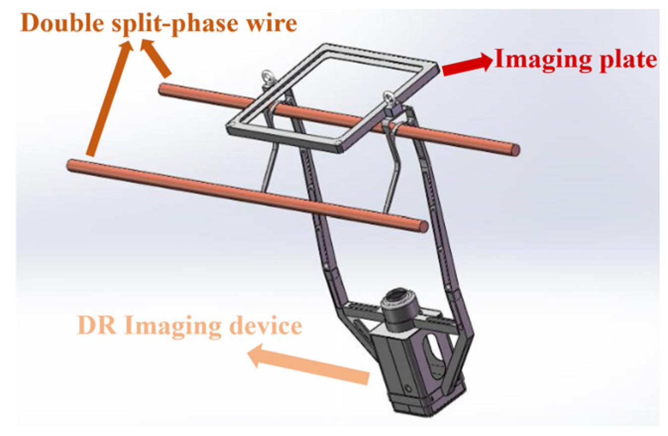
Currently, most UAV-based strain clamp inspections rely on a single heavy-duty rotorcraft carrying the necessary equipment to capture and transmit X-ray images to a ground station. While effective for single split-phase conductors, this method faces challenges with double split-phase conductors. The DR device to detect double split-phase conductors is schematically shown in
Figure 1. When the strain clamp is located on a multiple split-phase conductor, the space around the conductor decreases, the safety constraints imposed by the electromagnetic field become greater due to the increased voltage level, and the path margins for the UAV and inspection system to enter and exit the electromagnetic field become small or non-existent. This greatly increases the intensity and duration of the operator’s work, making the single UAV solution unsuitable for the detection of strain clamps on multiple split-phase conductors [
17].
Due to the complex environment of high-altitude transmission lines, it is difficult for the operator to accurately judge targets and distances using purely visual sensors. Therefore, we need to equip the vision sensor with some algorithms to reduce the operator’s burden [
18,
19,
20]. However, visual processing algorithms for transmission lines need to be improved, particularly in dealing with environmental disturbances such as light and fog [
21]. Additionally, the issue of distance detection in high-altitude transmission lines necessitates attention [
22], as the range of detection between the UAV and the target significantly impacts the safety and precision of the inspection. Therefore, this study proposed relevant algorithms to solve the problems of target detection and distance detection in high-altitude transmission lines in order to help the operator to judge the information of high-altitude images.
After successfully capturing and transmitting the X-ray images of strain clamps to the ground base station, the next challenge is to accurately classify defects to complete the inspection process. In practice, sufficient samples of normal terminals can be obtained during the initial crimping process, whereas building a fully defective sample set is a long and costly process that is currently almost impossible to achieve. Unsupervised training models are well suited to this situation. Furthermore, the knowledge distillation framework, which effectively extracts, summarizes, and disseminates valuable information, is particularly suited for leveraging a limited number of samples to power large-scale inspection tasks.
Currently, unsupervised anomaly-detecting algorithms are being developed to varying degrees, tailored to the specific requirements of the task. Among these, Knowledge Distillation for Anomaly Detection (KDAD) [
23] stands out as a superior alternative to self-supervised or single-class techniques that rely on autoencoder (AE) methods (e.g., SSIM-AE [
24], MSE [
25], etc.). Therefore, based on the idea of Salehi [
23] and others, an unsupervised defect detection method, KD-ResRPA, based on knowledge distillation was proposed, which was able to satisfy the requirements of accuracy and rapidity during detection.
In summary, this study proposed a dual-UAV-based charged detection system for strain clamps that carries the relevant equipment and deploys relevant algorithms for the charged detection of double split-phase conductor strain clamps. The main contributions of this work are outlined below.
- (1)
Aiming at the problem that it is difficult for a single UAV system to detect double split-phase conductors while guaranteeing its own safety, a dual-UAV-based electric detection system for strain clamps was constructed. For this system, a scheme of double-UAV system for charged detection of strain clamps was proposed. Through field experiments, it was proved that this scheme is suitable for the charged detection of double split-phase conductor strain clamps.
- (2)
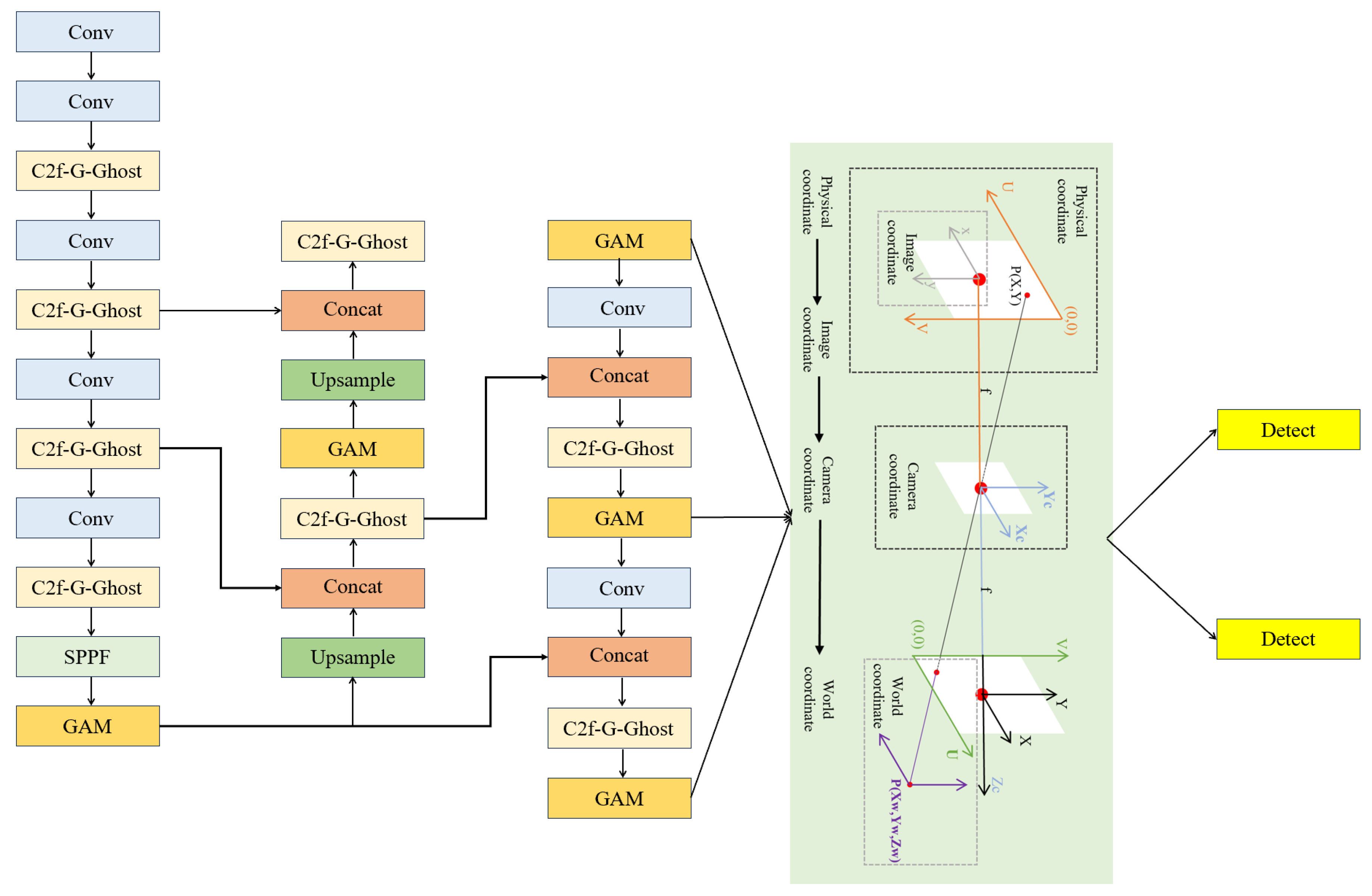
To reduce the operator’s burden in the complex environment of high-altitude transmission lines and to improve the operator’s judgement of the high-altitude information, a YOLOv8-TR model based on the improved YOLOv8n was proposed, which can be used for target detection and estimations of distance. Comparative experiments revealed that the improved algorithm achieved 2.4% and 2.0% enhancements in mAP@50 and mAP@50:95, respectively, while the F1-score improved by 0.5%. Moreover, it achieved accurate detection of the 3D coordinates at 3 m with 89FPS, enabling real-time and safe detection of strain clamps.
- (3)
An unsupervised defect detection method based on knowledge distillation, KD-ResRPA, was proposed to solve the problem of a severe lack of samples in the defect classification algorithm for strain clamps. Upon testing, the AUCROC of the improved model exhibited an approximately 2% increase compared with the original model, processing 22–24 images per second, thus satisfying the demands for real-time and accurate on-site charged detection of strain clamps.
The remainder of this study is structured as follows. In
Section 2, we outline the composition and functional requirements of the dual UAV system, describe the dual UAV system, and introduce a scheme for detecting strain clamps. In
Section 3, we provide detailed instructions for the development of the YOLOv8-TR model and the establishment of the KD-ResRPA network. In
Section 4, we demonstrate the superior performance of the YOLOv8-TR model in target detection through experiments, analyze its accuracy in distance detection, and validate the effectiveness of the KD-ResRPA network in detecting defects in strain clamps through comparative experiments. Additionally, we organized field tests to verify the overall system’s efficacy and the proposed scheme. Finally, in
Section 5, we summarize our conclusions and offer insights into potential future research directions.
2. System Overview
2.1. Hardware Components of the Dual UAV System
A single UAV system needs to carry both an emitting source (a DR transmitter) and a reflecting source (a digital imaging board) when performing charged detection of strain clamps. The working distance between the emitting and reflecting sources needs to be maintained at about 2 m, resulting in a large size for the single UAV system. The electromagnetic safety of the UAV, the transmitting source, and the reflecting source in the vicinity of the transmission line need to be considered simultaneously during the process of charged detection. When the strain clamp is located on a single conductor, the space near the conductor is more spacious, the security constraints imposed by the electromagnetic field are smaller, the path margins for the UAV and the detection system to enter and exit the electromagnetic field are larger, and the operational difficulty of the single UAV system completing charged detection is lower. However, when the strain clamp is located on a multiple split-phase conductor, the space near the conductor decreases and the voltage level rises, thus causing the safety constraints imposed by the electromagnetic field to become larger; the path margins of the UAV and the detection system into and out of the electromagnetic field become very small or even non-existent, which greatly increases the intensity of the operator’s work and the work’s duration, making the single UAV scheme unsuitable for the electrically charged detection of strain clamps on a multiple split-phase conductor.
In order to solve this problem, this study proposed a dual UAV system: one UAV carries the transmitting source (called the main UAV) and the other UAV carries the reflecting source (called the slave UAV). In this way, each UAV system is smaller in size and only needs to consider the safety of itself and one device (the emitting or reflecting source) when entering the electromagnetic field, with a larger margin in the operation path. With the help of the visual assistance system, the operator can complete the inspection of double split-phase conductors’ strain clamps with less operational intensity, while the dual UAV system ensures safety.
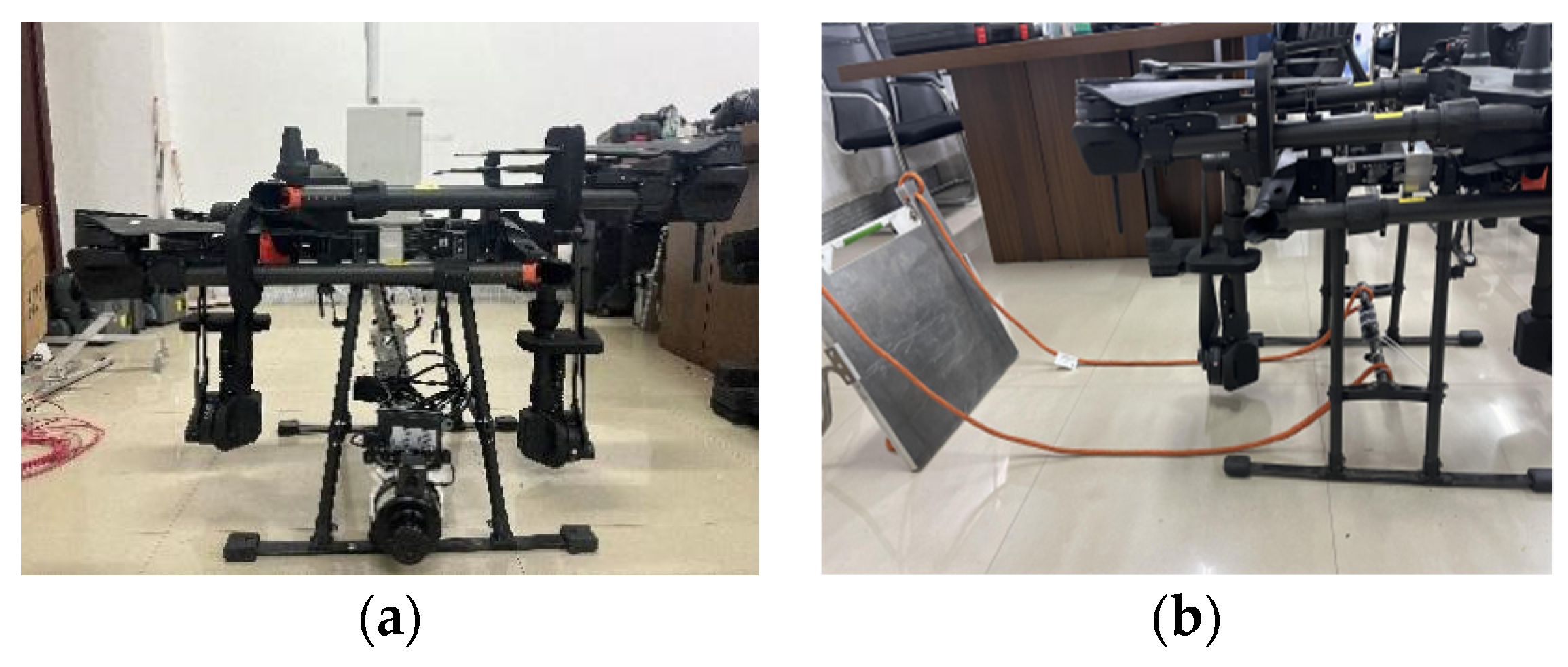
The dual UAV system built in this study is shown in
Figure 2 and consists of the following four parts: the UAV, the load of equipment for the task, the control cabinet, and the ground base station.
To acquire X-ray images of strain clamps, the main UAV’s load of equipment for the task must incorporate a DR transmitter. During the inspection process, as the UAV’s attitude cannot be directly adjusted due to environmental and other factors, a mechanical arm is required to manipulate the angle of the DR transmission device. This approach facilitates the capture of optimal X-ray images of strain clamps without altering the UAV’s attitude. To enhance the system’s integration, the communication module and the mechanical arm control system of the main UAV are integrated in one control cabinet.
To support the main UAV in capturing X-ray images of strain clamps, the slave UAV’s load of equipment for the task necessitates the integration of a digital imaging board. To ensure the stable carriage of this board, a pod suspension device was incorporated into the slave UAV’s design. This device suspends the digital imaging board and directs it to the designated location of the electrical equipment.
The ground base station consists of a host computer and a drone controller. The main UAV and the slave UAV are controlled by the drone controller. The host computer sends control instructions to the communication module to control the mechanical arm, the DR imaging device, and the suspension pod device. Information on the images from the binocular camera and the X-ray images of the strain clamp taken by the DR imaging device are received by the communication module and displayed on the host computer.
2.2. Overview of the Dual UAV System’s Workflow
In light of the unique characteristics of the system presented in this article and the operational demands for high-altitude transmission lines in the field, we have outlined the operational steps of this system in
Figure 3. The comprehensive workflow of the proposed system can be condensed into three distinct phases: navigation, imaging, and classification.
The initial phase, navigation, involves the dual UAV system ascending to the elevation of the strain clamp that requires measurement. Subsequently, the imaging phase commences, where the UAV system captures an X-ray image of the strain clamp and transmits it to the ground base station. Finally, the classification phase involves analyzing and categorizing any defects in the strain clamp after the dual UAV system has successfully captured and transmitted the X-ray images to the ground base station.
The process of navigation process will not be repeated in this article. The imaging and classification algorithms for the strain clamps are described in
Section 3.
4. Experiments and Analysis of the Results
4.1. YOLOv8-TR Verification
Given the diverse nature of strain clamps, to achieve the recognition of different types, we constructed a dataset of images of strain clamps and conducted experimental tests utilizing both self-built datasets (Self-data-RGB) and publicly available data (VOC 2007). Based on the specific application scenario, we selected two types of strain clamps, NY-300Q-1 and NY-50/30, to compile the self-compiled dataset. In total, 6680 images of strain clamp were screened and randomly partitioned into the training and validation sets, adhering to a ratio of 8:2. Some samples are presented in
Figure 10.
According to the amount of memory consumed in training of the dataset, selected on the basis of Ubuntu20.04 system service environment, where the hardware’s test environment for two NVIDIA 2080Ti graphics cards, each card contained 12 G of video memory. In this study, we used the Python language and pytorch as the basic framework of the network, and CUDA11.4 was used to accelerate the model’s training. For training, the images’ resolution was changed to 640 × 640 size by bisecting linear interpolation, and the optimizer was chosen to be the stochastic gradient descent (SGD). The model was trained for 300 epochs, with a batch size of 32 for each training session, in which the initial learning rate was 0.01 and the final learning rate reached 0.0001.
In this study, the
-score, mAP@50, and mAP@50:95 were used to evaluate the performance of target detection, where mAP denotes the average accuracy (AP) of n categories. The average mean average precision (amAP) was calculated as the average of the average precision for different classes. mAP@50 was derived by computing the mean average precision with an intersection over union (IOU) threshold set to 0.5. For each individual class, the AP was determined and then averaged across all classes to yield the mAP@50. Moreover, mAP@50:95 represents the mean average precision calculated over IOU thresholds from 0.5 to 95%, in increments of 5% intervals, resulting in a total of 10 thresholds. By averaging the AP values at these various thresholds, mAP@50:95 serves as a comprehensive evaluation metric that offers a holistic assessment of the model’s performance in object detection [
31]. For AP, it was obtained from the joint calculation of the precision (P) and recall (R), and the following equation reflects the relationship among P, R, mAP, and the
-score
where TP denotes the number of positive samples in the test target, FP denotes the number of negative samples in the test target, and FN denotes the number of positive samples that did not meet the target.
To rigorously evaluate the practical performance of various models, this study designed ablation experiments, as presented in
Table 1. Method (A) involved adding only the G-Ghost module behind the C2f module, while Method (B) incorporated the GAM module into YOLOv8n. Method (C), namely YOLOv8-TR (a YOLOv8 model capable of target detection and distance detection), integrated the G-Ghost module in C2f and included the GAM module in the network. The experiments demonstrated that YOLOv8-TR had increased of 2.4% and 2.0% in mAP@50 and mAP@50:95, respectively, while the F1-score improved by 0.5%, indicating its effectiveness in detecting strain clamps. In addition, YOLOv8-TR has been found to achieve a detection speed of approximately 89 frames per second, satisfying the real-time requirements of airborne edge-intelligent terminals.
In practice, recall and accuracy directly affect the efficiency of detection. Low recall means that some of the strain clamps that appear in the frame are not captured by the algorithm, which can result in missed detections. Low accuracy means that the algorithm may mistake other items in the frame for strain clamps, which reduces the efficiency of inspection. The higher the F1-score, the higher the recall and accuracy. mAP@50 and mAP50:95 reflect the detection rate of the model under different IOU thresholds, which can help the user to better evaluate the performance of the model. Therefore, improvements in the mAP@50, mAP50:95, and F1-score are of great significance for practical scenarios.
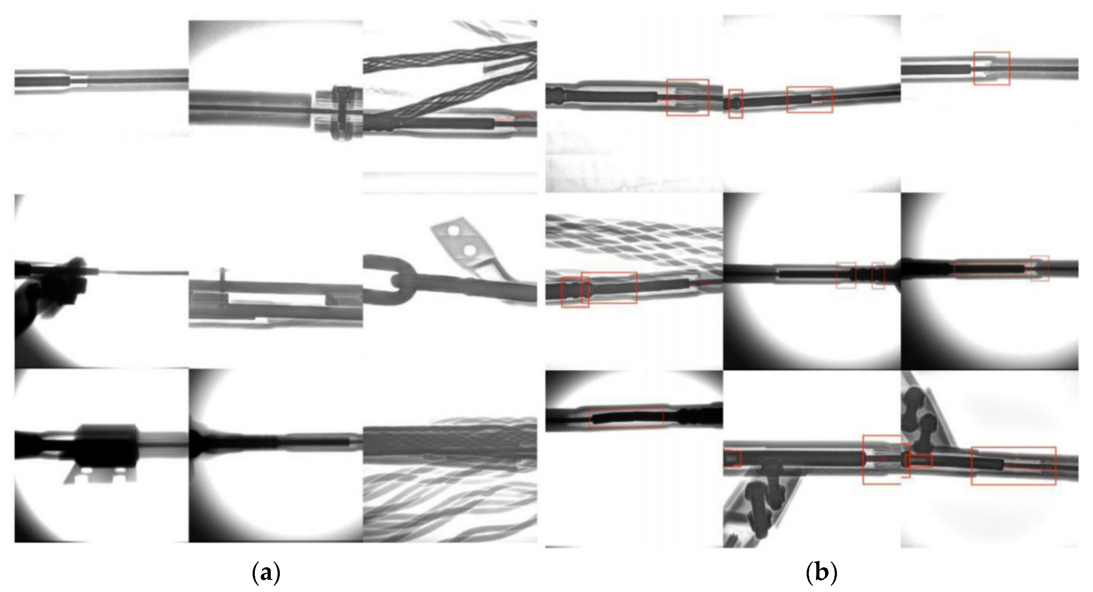
In this study, the performance of detecting two types of samples, NY-D10 and NY-D20, in different environments in our self-built dataset was compared using the proposed YOLOv8-TR algorithm. The results are shown in
Figure 11.
Figure 11a depicts the images detected by the original algorithm, where the first image shows the detection of an NY-D10 in a foggy environment, the second image depicts the detection of a strain clamp in an environment with normal lighting, the third image represents the detection of an NY-D20 under strong lighting, and the fourth image illustrates the detection of an NY-D20 in a normal environment.
Diagrams of the improved algorithm’s detection are shown in
Figure 11b. The first image shows that it is more effective in detecting objects at a long distance. The second image shows that it is able to detect objects under semi-obscurity. The third image shows it is obviously able to cut down the influence of strong light, refine the environmental background features, and obtain the corresponding target box. The fourth image shows it is able to extract its depth information and obtain the position of a strain clamp after being covered.
The distance detection algorithm was validated at the experimental site. We compared the coordinates of the positive center of the target detection box of the strain clamp at 1 m, 3 m, and 5 m from the lens. As shown in
Table 2, the detection error at 1 m was large, the detection error at 5 m was the second largest, and the detection error at 3 m was the smallest, not more than 1%. In practice, errors in distance detection affect the safety of the system and determine whether X-ray pictures of strain clamps can be successfully taken. The results can meet the requirements of the charged detection of strain clamps.
4.2. Verification of the Classification Mode
Using the dual UAV system described in this article, X-ray images of the strain clamps were acquired at a safe imaging distance. These images were then transmitted to the ground base station via a communication module, where they were subjected to identification and processing using the proposed unsupervised learning method.
The datasets of images strain clamps with defects were categorized into two types: shooting defect datasets (SD-data) and intrinsic defect datasets (ID-data). Shooting defects refer to those cases where the captured images do not accurately reflect the actual condition of the inspected strain clamps due to factors such as the imaging device’s angle, the shooting distance, or the presence of obscuring objects during the process of image acquisition. The intrinsic defects are caused by quality problems after the strain clamps are put into use or by operating in high-altitude and high-pressure working environments for a long period of time. These defects encompass, but are not limited to, leakage of pressure in the crimping area, lack of pressure in the crimping area, accumulation of water within the aluminum tube in non-crimped regions, and damage to fittings in non-crimped areas. Some samples are presented in
Figure 12.
In total, 1442 DR images of strain clamps were collected, each with a resolution of 3044 × 2498 pixels. These images were then categorized into 274 normal samples and 1168 defective samples by the specified requirements. The defective samples were further divided into 584 shooting defects and 584 intrinsic defects. To simulate the detection of unknown defects in real-world scenarios, the dataset was partitioned into a training set comprising 247 normal samples and a test set consisting of 27 normal samples and 1168 defective samples. For training purposes, the images’ size was reduced to 128 × 128 pixels, and the images were converted to grayscale. The k parameter was set to 0.8.
These models and data were trained on an NVIDIA RTX 2080Ti with a software environment of NVIDIA-SMI 470.103.01, driver version 470.103.01, CUDA 11.4, etc. The Adam optimizer [
32] was used for optimizing all experiments, with the learning rate set to 0.001, a batch size of 16, bias-free training, and a total of 300 epochs. The performance of the models was evaluated after convergence, utilizing the AUCROC (area under the receiver operating characteristic curve) as the primary evaluation metric.
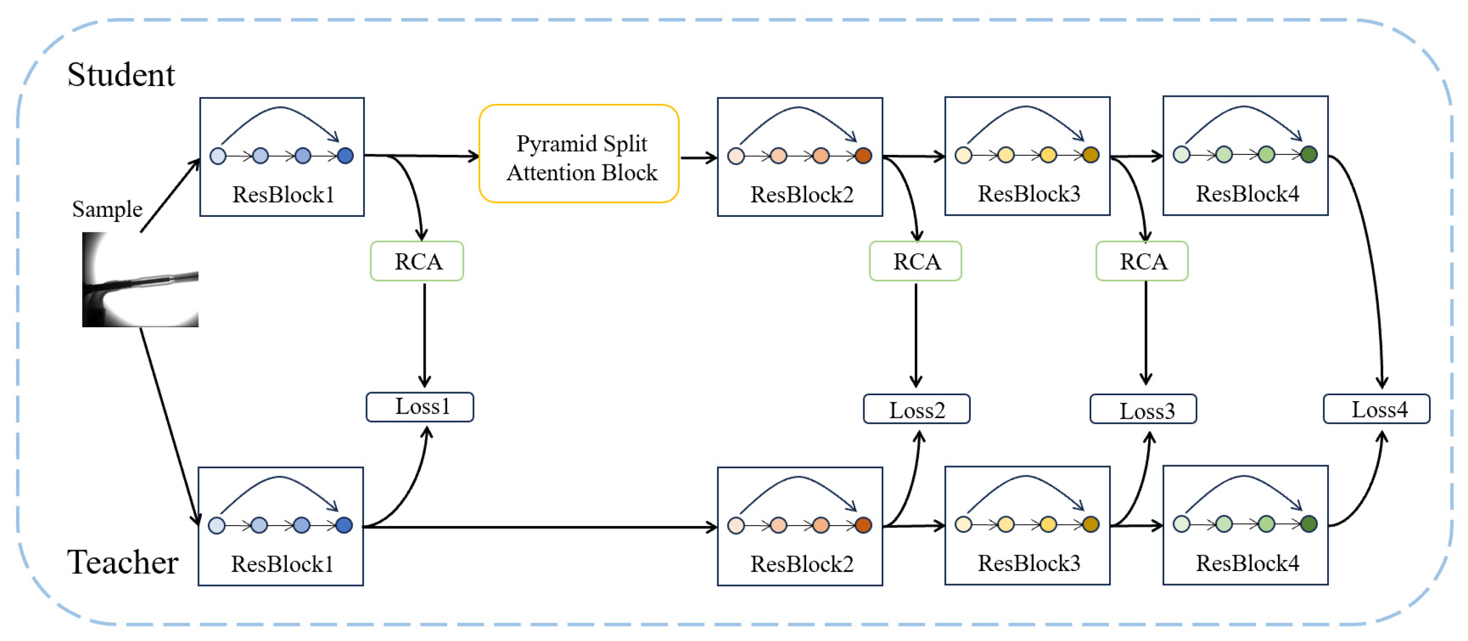
To facilitate analysis of the data, we utilized ResNet50 as a student model and defined the original teacher models with 101 and 50 layers as M1 and M2, respectively. The improved frameworks are denoted as M3 and M4, as depicted in
Table 3. And we have uniformly named the M3 and M4 network frameworks KD-ResRPA (knowledge distillation + ResNet + teacher-student model + RCA + PSA).
To validate the efficacy of the proposed unsupervised method in detecting defects in strain clamps, experiments were conducted on a proprietary dataset of strain clamps. As presented in
Table 4, three distinct test cases were evaluated: a test set comprising solely of intrinsic defects (ID-data), a test set comprising solely of shooting defects (SD-data), and a test set encompassing all types of defects.
Due to the incompleteness of the dataset, there were fluctuations in the model’s training results. To enhance the credibility of the test outcomes, we conducted three separate training sessions for each case and utilized the average of the final results as a rating indicator. The results of these experiments are depicted in
Figure 13.
The experimental results validated the efficacy of the proposed KD-ResRPA algorithm in detecting defects in strain clamps. Only a small number of positive samples needed to be provided to the unsupervised model to motivate the model to find the space that best matched the positive samples, enabling the model to perceive anomalous images in the input data well.
In the longitudinal comparison presented in
Figure 13, M1 demonstrated a higher AUCROC than M2 by about 0.3–1% in each sample set; similarly, M3 outperformed M4 in terms of AUCROC by about 0.3–1%. This indicates that for this specific dataset of strain clamps, using the approach where the student model was smaller than the teacher model yielded superior results compared with when the student model was equivalent to the teacher model. Furthermore, the AUCROC of M3 was consistently higher than that of M1 by about 1–2%, and the AUCROC of M4 was consistently higher than that of M2 by about 1–2% across all sample sets. This validated that the improved network structure, achieved by incorporating RCA and PSA, outperformed the pre-improved structure. M3 had an average AUCROC of about 82.7% over the three sample sets, which was the optimal model. The higher the AUCROC, the better the model could differentiate between the presence or absence of defects in the strain clamps. In practical scenarios, our judgements of whether a strain clamp is defective or not and which kind of defect it is are of great significance for the operation and maintenance of the power grid.
The side-by-side comparison in
Figure 13 reveals that frameworks with both equal and non-equal teacher–student model were more sensitive to shooting defects, which is crucial for the real-time monitoring of strain clamps. Shooting defects refer to the fact that the shooting equipment does not take a comprehensive enough photo of the strain clamps, and if potentially fatal defects appear in the unshootable areas, they may pose a huge safety hazard to the HV transmission line. Our model was very sensitive to shooting defects, which would also enable the operator to adjust the shooting equipment in time. Furthermore, the test results across different cases fluctuated within an acceptable range, indicating that the influence of the dataset and the shooting equipment on the model’s performance was minimal, thereby demonstrating the good robustness of our model. Finally, tests showed that our model was capable of processing 22–24 images per second, satisfying the real-time requirements for on-site charged detection of strain clamps.
4.3. Field Operation
A dualUAV-based system for the charged detection of strain clamps was built, as shown in
Figure 14. The system consisted of four parts: a drone as described in
Section 2, a DR imaging device, a control cabinet, and a ground base station. Among them, the DJI T20 heavy-duty drone was used for the drone, a Jetson Nano was used for the edge intelligence module, and an STM32F407ZGT6 was used for the MCU of the mechanical arm’s control system and the suspension pod’s control system.
We used the process described in
Section 2.2 to complete the field experiment. The main UAV carried the DR transmitter to a position about 3 m above the strain clamp to be tested and ensured that the horizontal distance between the DR transmitter and the tested strain clamp was maintained at about 2 m. At the same time, the slave UAV flew to a position about 3 m above the strain clamp and ensured that the digital imaging board it carried maintained a horizontal distance of about 15 cm from the measured strain clamp. The operator relied on the returned visual images and information to judge whether the conditions of shooting were met (the DR transmitter, the strain clamp, and the digital imaging board were in the same straight line). If it did not meet the shooting conditions, fine-tuning was carried out. If the conditions of shooting were met, the operator controlled the ground terminal host computer to send “shooting” commands to the DR transmitter. After shooting, the X-ray image of the strain clamp was returned and displayed on the host computer.
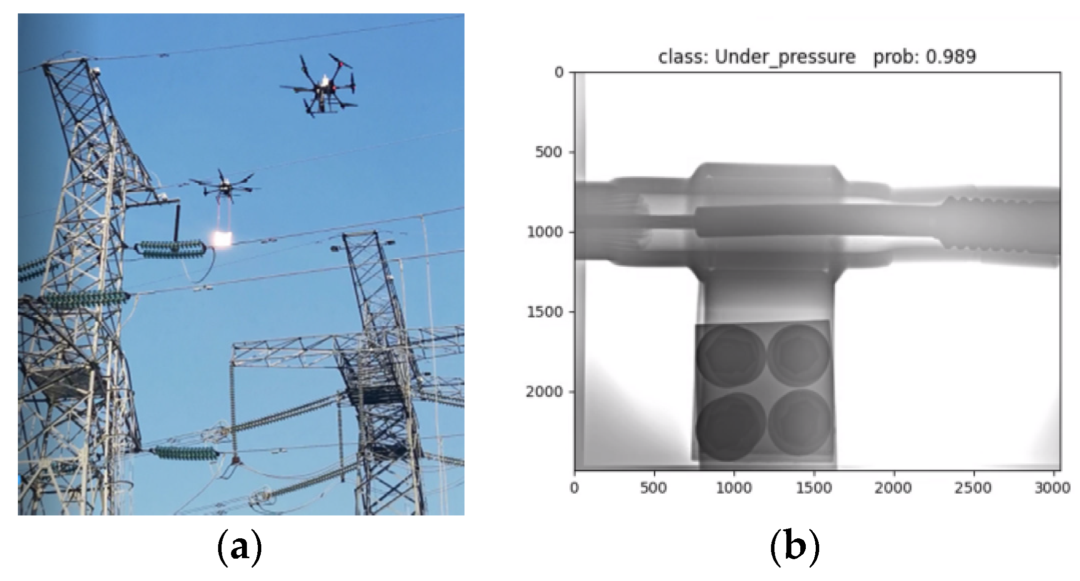
A field test was conducted for the charged inspection of a double split-phase transmission tower featuring a left–center–right phase structure, as depicted in
Figure 15. The results of this field test demonstrated that the proposed dual-UAV-based system could precisely capture X-ray images of strain clamps under charged conditions and accurately detect defects in these X-ray images.
5. Conclusions
With the booming scale of high-voltage overhead transmission lines, regular inspection of strain clamps has become increasingly important. Currently, this mainly relies on a single UAV carrying both an emitting source (DR transmitter) and a reflecting source (digital imaging board) to complete the acquisition of X-ray images of strain clamps. This method achieves a good job of detecting single split-phase conductors, but it is difficult to detect multiple split-phase conductors while keeping a single UAV system safe. Moreover, due to the interference caused by environmental factors such as light and fog in high-altitude transmission lines, higher requirements have been put forward for target detection by UAV systems. At the same time, the problem of detection of the distance of high-altitude transmission lines needs to be solved. In practice, it is difficult to build a complete and sufficient sample library of defects of strain clamps due to the high risk and difficult operation of transmission lines with electricity, and the difficulty of collecting defective samples.
In response to the problems above, this study proposed appropriate solutions.
- (1)
Aiming at the problem that it is difficult for a single UAV system to detect double split-phase conductors while guaranteeing its own safety, a dual-UAV-based electric detection system for strain clamps was constructed. The main UAV was equipped with a digital radiography (DR) imaging device, a mechanical arm, and an edge intelligence module with visual sensors. The slave UAV was equipped with a digital imaging board and visual sensors. For this system, a scheme of the double-UAV system for charged detection of strain clamps was proposed. Through field experiments, it was proved that this scheme is suitable for the charged detection of double split-phase conductor strain clamps.
- (2)
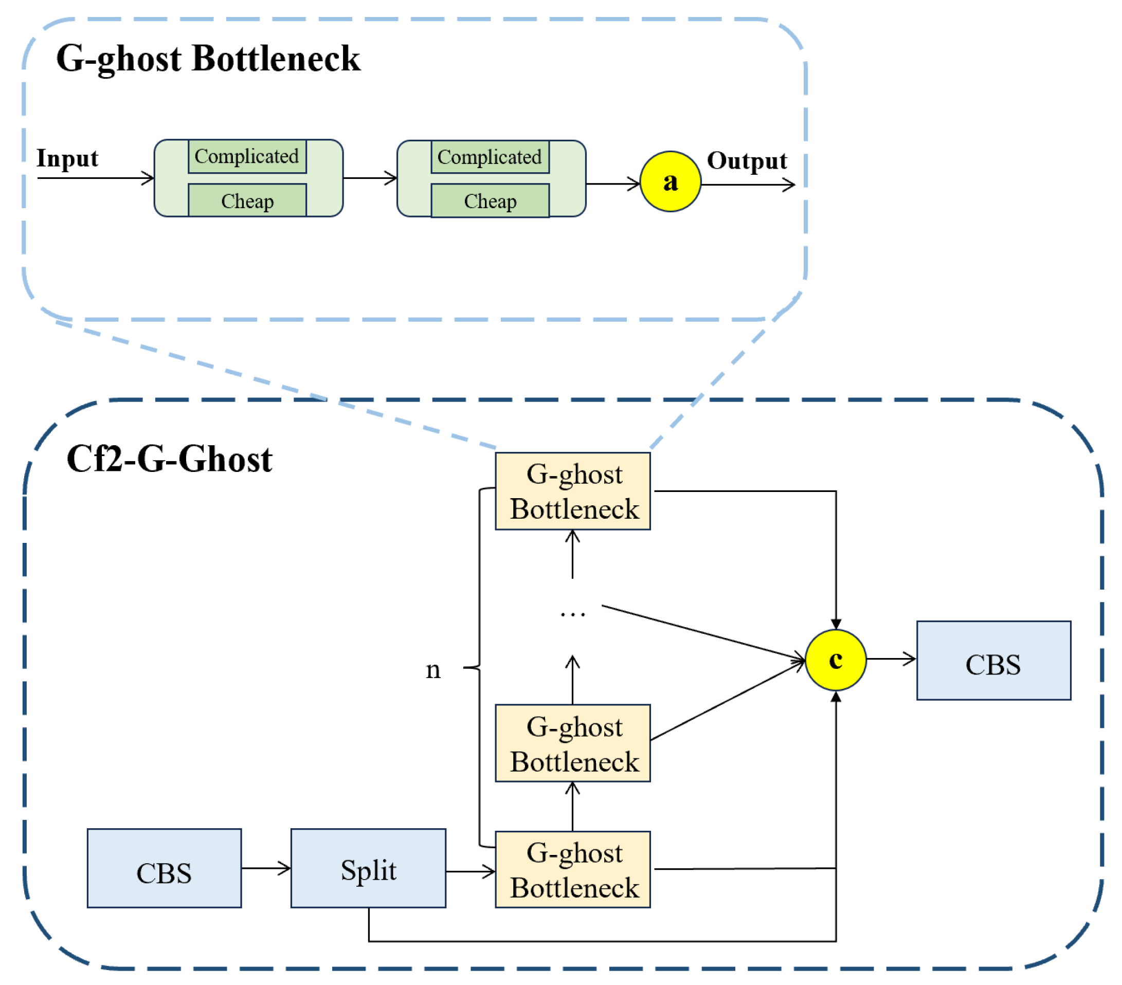
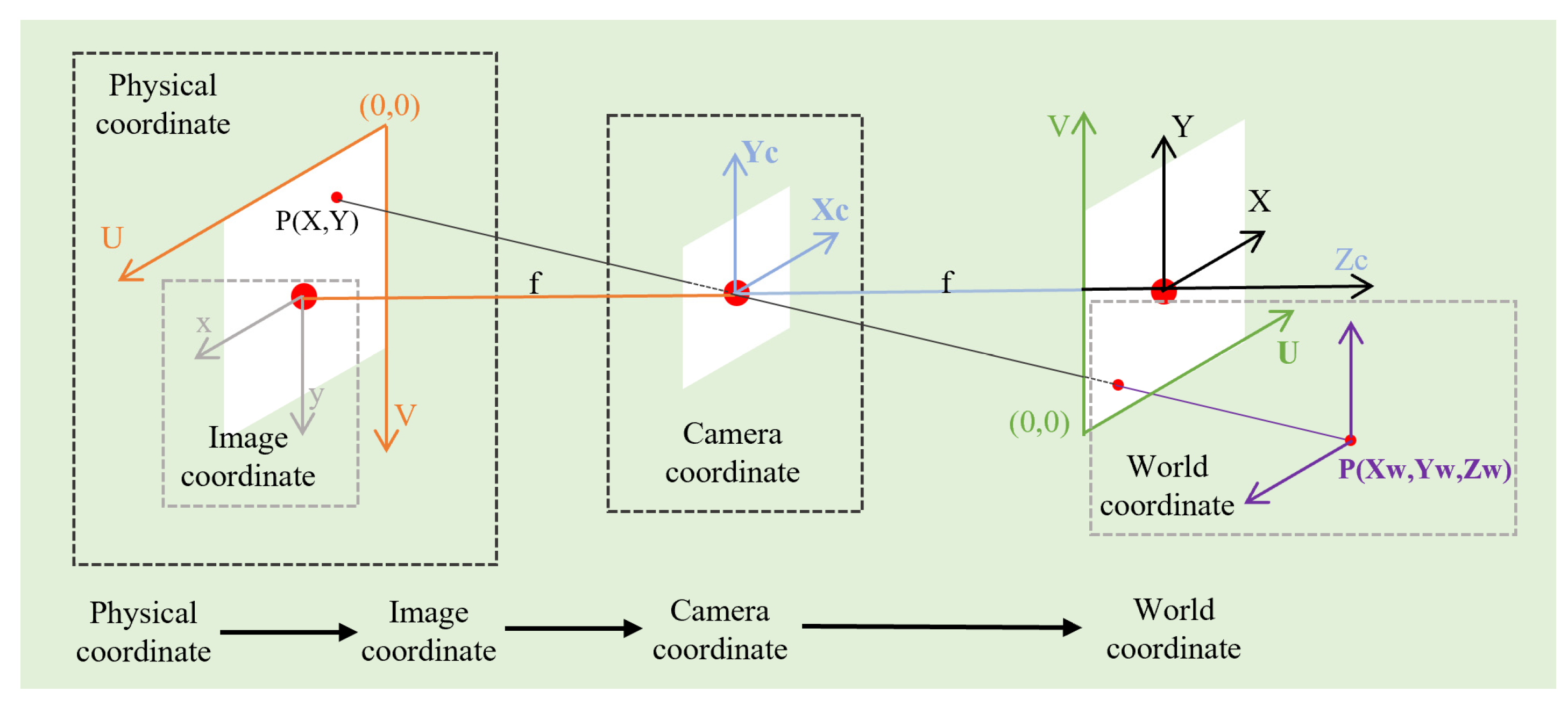
In order to reduce the operator’s burden in the complex environment of high-altitude transmission lines and to enhance the operator’s judgement of high-altitude information, a YOLOv8-TR model based on the improved YOLOv8n was proposed, which can be used for target detection and distance detection. Firstly, the G-Ghost module was added to the C2f module of YOLOv8, which was used to compress the size of the model and, at the same time, speed up the extraction and fusion of features by the model. Second, the GAM attention mechanism was added to the backbone network to further improve the detection accuracy of its model. Finally, a 3D detection algorithm was added in front of the detection head to achieve accurate positioning of the binocular camera. Comparative experiments revealed that the improved algorithm achieved 2.4% and 2.0% enhancements of the mAP@50 and mAP@50:95, respectively, while the F1-score improved by 0.5%. Notably, the detection of 3D coordinates was most precise at 3 m, and the detection speed reached 89 frames per second (FPS), enabling real-time and secure detection of strain clamps.
- (3)
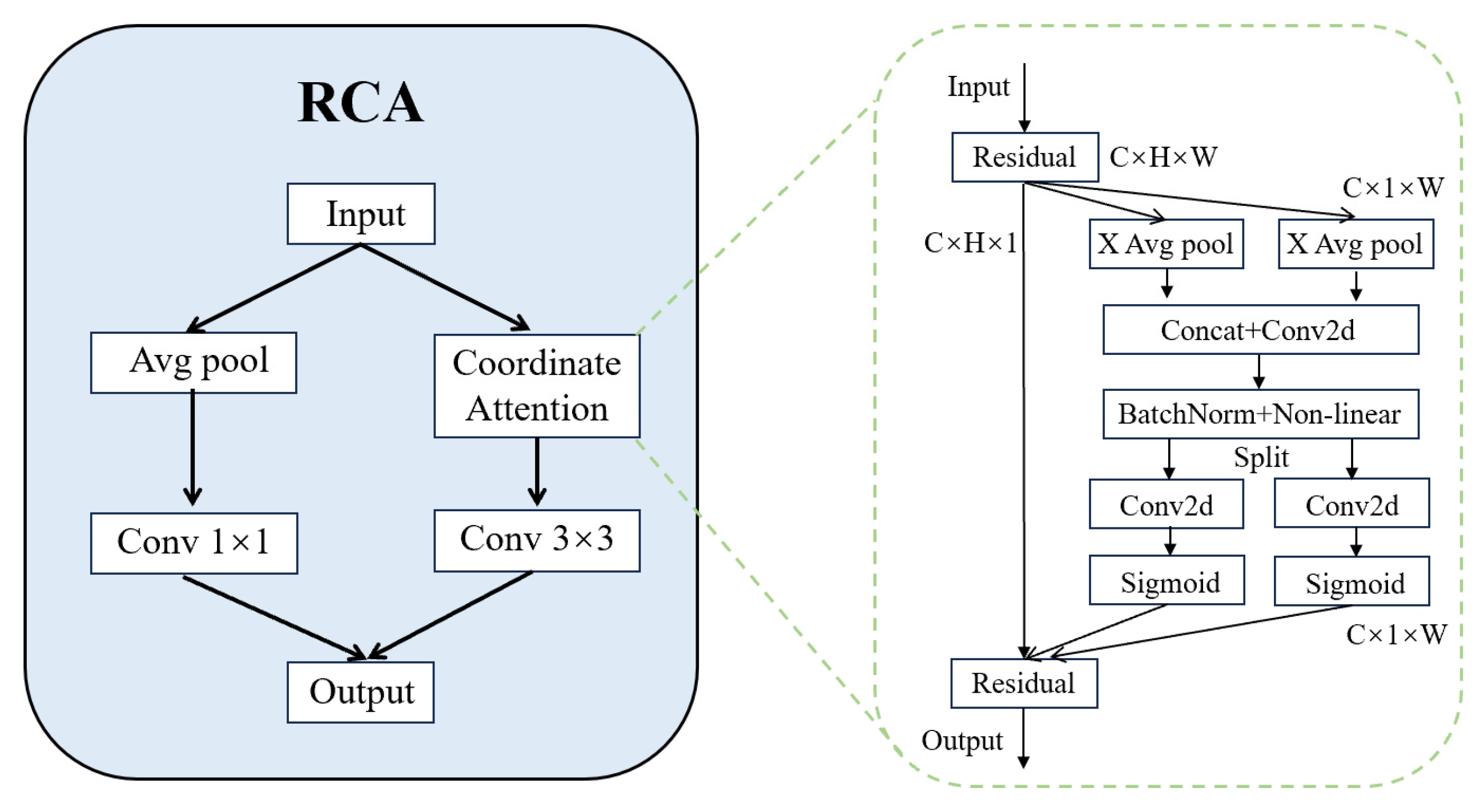
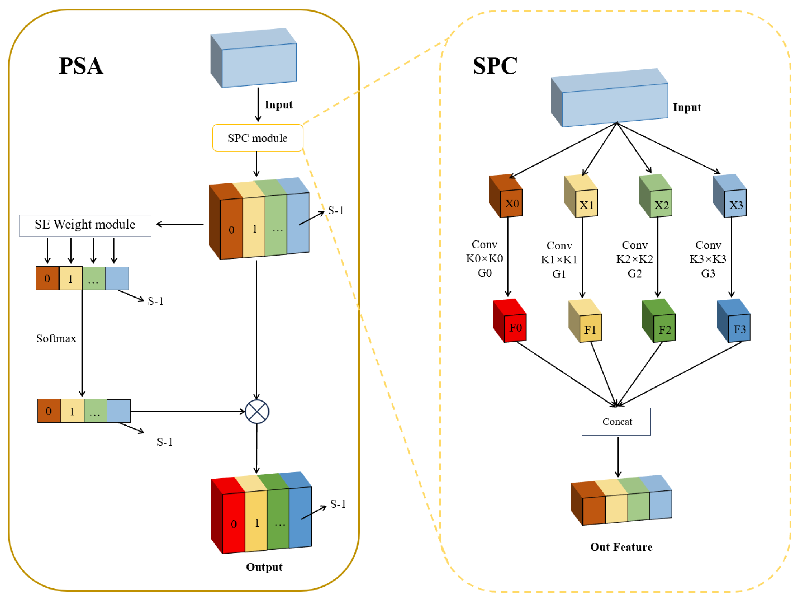
An unsupervised method of defect detection based on knowledge distillation, KD-ResRPA, was used to address the problem of a severe shortage of defective samples of X-ray images of strain clamps. Firstly, ResNet served as the backbone network to address the challenges of vanishing and explosion of the gradient during the model’s training. Subsequently, a PSA module was integrated into the shallow layers of the student models, enhancing their capacity to capture the input images with multiscale information. Furthermore, an RCA module was adopted to help the lower-level students to review their knowledge before receiving instruction, thereby improving their perception of the spatial location and establishing global dependencies across the student models. Upon testing, the AUCROC of the improved model exhibited an increase of approximately 2% compared with the original model, processing 22–24 images per second, thus satisfying the demands for real-time and accurate on-site charged detection of strain clamps.
However, the solution of this study has the following limitations and unknowns.
- (1)
In this study, we only conducted targeted experiments on strain clamps and not on other electrical fittings (e.g., vibration-proof hammers and bolts). Therefore, the applicability of this scheme to the testing of high-voltage overhead transmission lines’ fittings other than strain clamps is a point that needs to be verified urgently.
- (2)
In this study, we addressed the problem that a single UAV system cannot detect strain clamps on double split-phase conductors. We used a double UAV system to complete the charged detection of double split-phase conductor strain clamps. For quad split-phase conductors, we did not carry out the related exploration and experiments. We do not know whether the real-time and accuracy of the system and algorithm in this study can reach the standard of charged detection of quad split-phase conductors.
In the future, we will further optimize the scheme to make the visual inspection of the UAV more intelligent, reduce the burden of the flyer in the process of manipulating the UAV, and further improve the efficiency and safety of the inspection. We will also further expand the capability of the system for generalization from the charged detection of strain clamps to the charged detection of various electrical fittings (e.g., vibration-proof hammers and bolts), and from double split-phase lines to quadruple split-phase lines.
