Abstract
This paper proposes a systematic approach for identifying the translational dynamics of a novel two-layer octocopter. Initially, we derive the non-linear theoretical dynamic model of the conventional octocopter using the Newton–Euler formulation, aimed at obtaining a simplified model suitable for tuning PID gains necessary for controller implementation. Following this, a controller is designed and tested in the Matlab/Simulink environment to ensure stable flight performance of the octocopter. Subsequently, the novel octocopter prototype is developed, fabricated, and assembled, followed by a series of outdoor flight tests conducted under various environmental conditions to collect data representing the flight characteristics of the two-layer vehicle in different scenarios. Based on the data recorded during flights, we identify the transfer functions of the translational dynamics of the modified vehicle using the prediction error method (PEM). The empirical model is then validated through different flight tests. The results presented in this study exhibit a high level of agreement and demonstrate the efficacy of the proposed approach to predict the octocopter’s position based only on motor inputs and initial states of the system. Despite the inherent non-linearity, significant aerodynamic interactions, and strongly coupled nature of the system, our findings highlight the robustness and reliability of the proposed approach, which can be used to identify the model of any type of multi-rotor or fixed-wing UAV, specifically when you have a challenging design.
1. Introduction
In recent years, the development of unmanned aerial vehicles (UAVs) has seen rapid growth due to technological breakthroughs in various areas, including power storage systems, MEMS sensors, remote control capabilities, navigation systems, and fabrication technologies [1,2]. These advancements have significantly enhanced UAV flight capabilities, autonomy, payload capacity, safety, and reliability [3,4]. Consequently, UAVs are now employed in extensive civilian and military applications, including delivery services, search and rescue, environmental monitoring and conservation, military and law enforcement, surveying and mapping, and other miscellaneous applications [5,6,7]. UAVs are currently classified, based on their physical configuration, into two principal categories: fixed-wing and rotorcraft UAVs [8]. Among rotorcraft UAVs, multi-rotors have become widely used, thanks to their unique capabilities such as vertical take-off and landing (VTOL), hovering, agility, and high maneuverability [9]. Octocopters are multi-rotors equipped with eight rotors that are generally positioned equidistantly on the vertices of an octagon. They offer improved redundancy, stability, and enhanced payload capacity due to their eight-motor configuration [10,11,12,13,14]. Two prevalent designs for octocopters are the conventional and coaxial configurations. In the conventional setup, eight arms are equipped with eight motors, whereas the coaxial arrangement, as described in [15], features four arms, each incorporating two motors positioned one above the other. The authors in [16] introduced a novel design consisting of eight rotors arranged in two layers, capable of generating a remarkable 41.5% increase in thrust compared to a coaxially configured octocopter with identical rotor blade size. Furthermore, in contrast to conventional octocopter designs with equal arm length, this configuration exhibits a remarkable 71% boost in thrust due to the ability to utilize larger propellers with the same arm length. This design improves the payload capacity in limited geometric sizes.
Achieving stable and robust control for this innovative configuration is one of the major challenges to the successful flight of this model, particularly for missions requiring precise positioning and altitude control. Therefore, developing an accurate model that characterizes the dynamic behavior of the system and overcomes the complexity of this model, which has significant aerodynamic interactions and intricate airflow patterns, coupled with the inherent attributes of this highly non-linear, multi-input multi-output (MIMO), strongly coupled, and intrinsically unstable system, is extremely imperative [17].
In modeling such a system, two primary approaches are commonly employed: the first principle of modeling and system identification [18]. The former is derived from the laws of mechanics and aerodynamics to obtain the non-linear model, which requires certain assumptions to simplify the model, whereas the system identification approach develops models directly from observed input–output data to address all these uncertainties and create a model that accurately depicts the system’s dynamics [17]. Ljung’s literature review [19] introduced methods for system modeling and identification, ranging from a white box to a black box. White models estimate parameters from measured data based on first-principles modeling, where physical parameters, such as mass, moment of inertia, and motor constants, are obtained from actual measurements using software or experimental methods [20]. However, this is still a challenging task that has not yet been entirely tackled [17].
On the other hand, gray-box modeling combines the measured input–output data with prior information about the dynamic representation of the system [21]. In the study by [22], gray-box modeling was used to identify the dynamics of a quad-copter in accelerated flight, demonstrating improved modeling accuracy and robustness against noise. Similarly, the authors in [23] constructed a gray-box model to identify the aerodynamic forces and moments during high-speed flight, and the model exhibited high prediction accuracy and successfully identified the dynamics of the quadrotor.
In contrast, the black-box model is obtained without any prior physical knowledge or insight about the model, and it is directly modeled from the measured input–output data as discussed in [24,25]. The study presented in [20] used a black-box neural network model to learn the dynamics of the quadrotor, and the model was able to capture and handle the system’s intricacies.
Despite extensive studies on system identification in UAV dynamics, a notable research gap exists concerning the dynamic model identification of octocopters, particularly regarding position identification, which is a challenging task that involves identifying the closed-loop model of the octocopter during outdoor flights. Our study focuses on modeling the translational dynamics using flight test data, which is considered an essential feature for applications requiring high location accuracy, such as imaging and remote sensing.
The contributions of this paper are summarized as follows:
- We present the transfer function identification of a novel two-layer octocopter that features a remarkable increase in thrust compared to conventional and co-axial configurations.
- System identification is proposed based on recorded real-world flight test data, and the transfer functions governing the position and altitude of the model are identified using the prediction error method (PEM).
- The proposed identified transfer functions are considered a black-box model, providing a closed-form solution that directly correlates motor inputs with the vehicle’s position. This enables direct prediction of the vehicle’s location based on motor inputs, which is a novel approach, given the model’s high non-linearity, parameter uncertainty, and susceptibility to measurement noise.
To achieve this, we created a Matlab Simulink model to represent the theoretical dynamics of the conventional octocopter to obtain a simplified model for initial controller gain tuning to ensure stability and optimal performance. Subsequently, we developed and manufactured a hardware prototype from scratch, assembled it, and conducted real-world flight tests to collect data for the identification process, which were filtered using an Extended Kalman Filter to obtain accurate position data. Finally, we employed our model and validated the accuracy of the obtained system models through diverse flight tests conducted in various locations and environmental conditions.
The paper is organized as follows: in Section 2 the dynamic model of the octocopter is derived using the Newton–Euler model. Section 3 delves into the development of the closed-loop theoretical model, including the design, implementation, and testing of the controller. The hardware setup and the data collection process through flight tests are presented in Section 4. Section 5 details the approach followed in the identification and validation experiments. Finally, in Section 6, we present the results obtained from estimating the identified model and the analysis of its characteristics.
2. Dynamic Model of the Octocopter
In this paper, we mainly focus on modeling the two-layer octocopter. However, here, we present the dynamic model of the standard octocopter, as the fundamental equations governing the dynamics of both configurations are equivalent despite their structural differences. This arises from the fact that the driving motors in both configurations are all mounted perpendicular to the UAV body frame. Consequently, these motors generate thrust force in the direction perpendicular to the UAV frame, as well as three independent torques around its three body axes. The main structural difference lies in the inertia matrix, where the two-layer configuration features off-diagonal elements. However, considering that the magnitudes of these off-diagonal elements, when compared to diagonal elements derived from the CAD file, are three orders of magnitude lower, the assumption of a symmetrical structure remains quantitatively valid. The dynamic model of the octocopter is derived based on the work presented in [26,27,28]. To facilitate the development of the dynamic model for the octocopter, we consider the following assumptions and hypotheses:
- The octocopter is modeled as a rigid body affected by a single lift force and three types of torques.
- The octocopter has a symmetrical structure, which implies that the inertia matrix has only diagonal elements.
- The center of gravity coincides with the origin of its fixed frame of reference.
- The rotors are assumed to be rigid, so the effect of their deformation during rotation can be neglected.
- The lift forces and motor speeds are supposed to be proportional to the square of the rotors’ rotational speed, which is a very close approximation to the aerodynamic behavior.
2.1. Kinematics
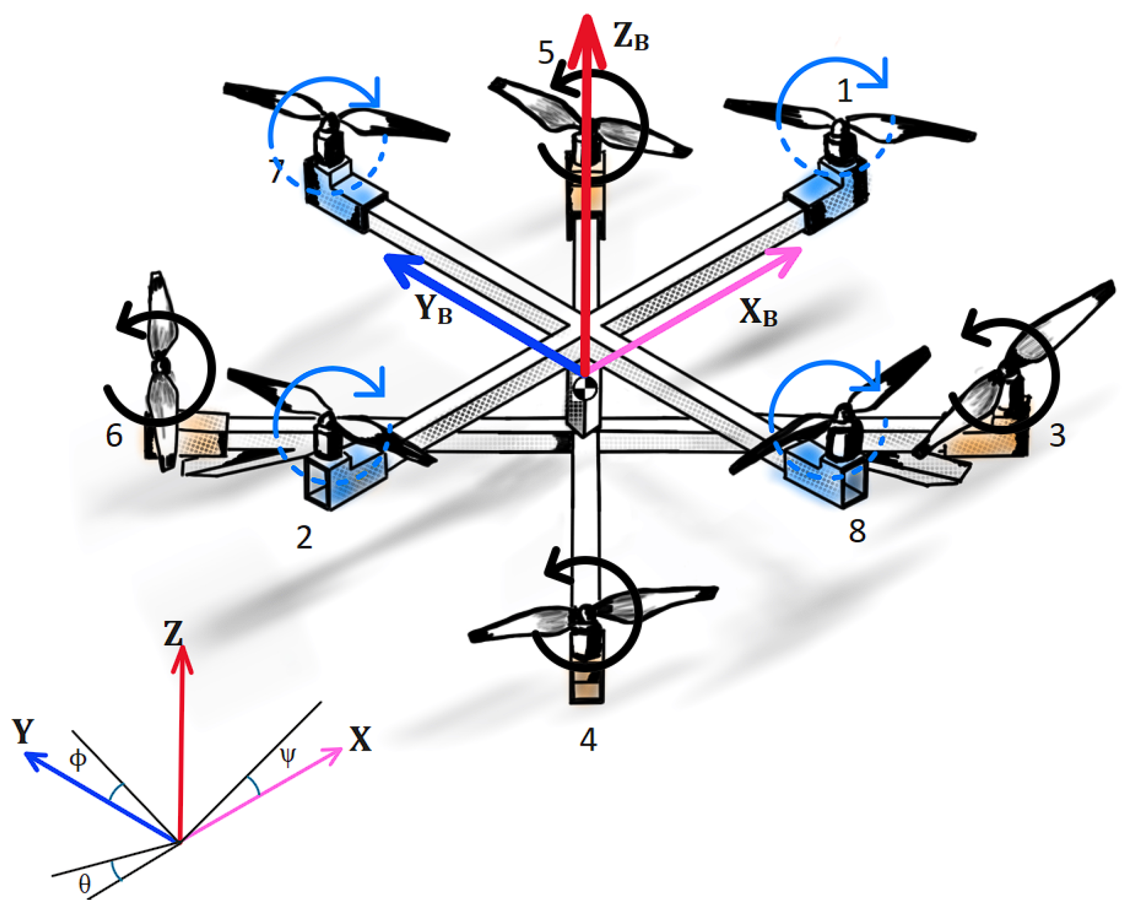
As depicted in Figure 1, we define two coordinate systems: an inertial frame at a specific ground-level location, and a body-fixed frame at the octocopter’s center of gravity. The octocopter’s linear position within the inertial frame, defined by the axes, is designated by the vector . On the other hand, the orientation of the octocopter is denoted by the vector , with each element representing one of the three Euler angles: roll (), pitch (), and yaw (). These angles determine the rotations around the x, y, and z axes, respectively.
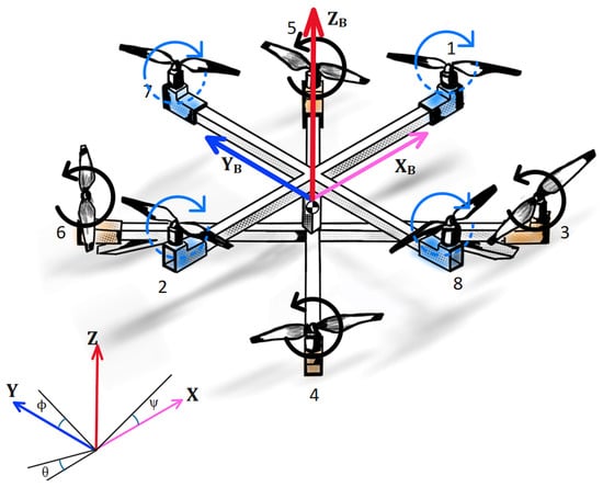
Figure 1.
The inertial and body frames of the octocopter.
The rotation matrix, denoted as R, provides the transformation between the body-fixed frame and the inertial frame. This matrix is derived based on the sequence of principle rotation: first around the z axis, then around the y axis, and finally around the x axis:
where C denotes cos and S denotes sine.
The transformation between the rates of Euler angles in the inertial frame denoted as and the angular velocities measured in the body frame, represented as is defined as follows:
where
The non-linear model of the octocopter is approximated around the hovering equilibrium point by assuming small roll and pitch angles, which applies and . This approach reduces to the Identity Matrix . As a result:
2.2. Dynamics
In order to derive the equations of motion and develop the dynamic model of the octocopter, we applied the Newton–Euler method.
The translational equation of motion is derived as follows:
where is the total thrust of rotors.
The rotational equation of motion is defined as:
where M is the external torque applied to the octocopter, and H is the angular momentum. The above equation can be written as:
where is the angular velocity and I denotes the moment of Inertia tensor, . Substituting into Equation (9), we obtain:
By combining the translational motion described by Equation (7) and the rotational motion captured by Equation (10), we can now present the complete non-linear dynamic model of the octocopter:
The thrust force and torque M are generated due to the angular rotation of rotors, in which each rotor generates force in the rotor axis direction. In addition, it generates torque around its axis:
where k and b denote the lift coefficient and the drag factor, respectively. These coefficients link the square of the motor’s angular speed proportionally with the resulting force and torque. They are positive parameters determined by the shape of the blades and the air density, and are typically derived from experimental measurements [29]. Therefore, the total thrust vector () exerted on the body axes can be defined by adding the forces of the eight rotors:
In our model, there are two sets of rotors: those in the (+) position rotate clockwise, while the rotors in the (×) position rotate counterclockwise, and the angle between each rotor is 45 degrees. The moment about the axis is created due to the difference between the lift forces of rotors 3, 4, 8 and 5, 6, 7 as follows:
where l is the length of the arm between the rotor and the center of gravity of the octocopter.
Similarly, the moment about the axis is given by the following relation:
The moment around the axis is created by the reactive torque generated by the opposing sets of rotors. This moment can be represented as follows:
Now we can combine all these equations and define the total force and the total torque applied on the octocopter around the x, y, and z-axes in terms of the rotors’ angular velocities as follows:
3. Controller Design and Simulation Setup
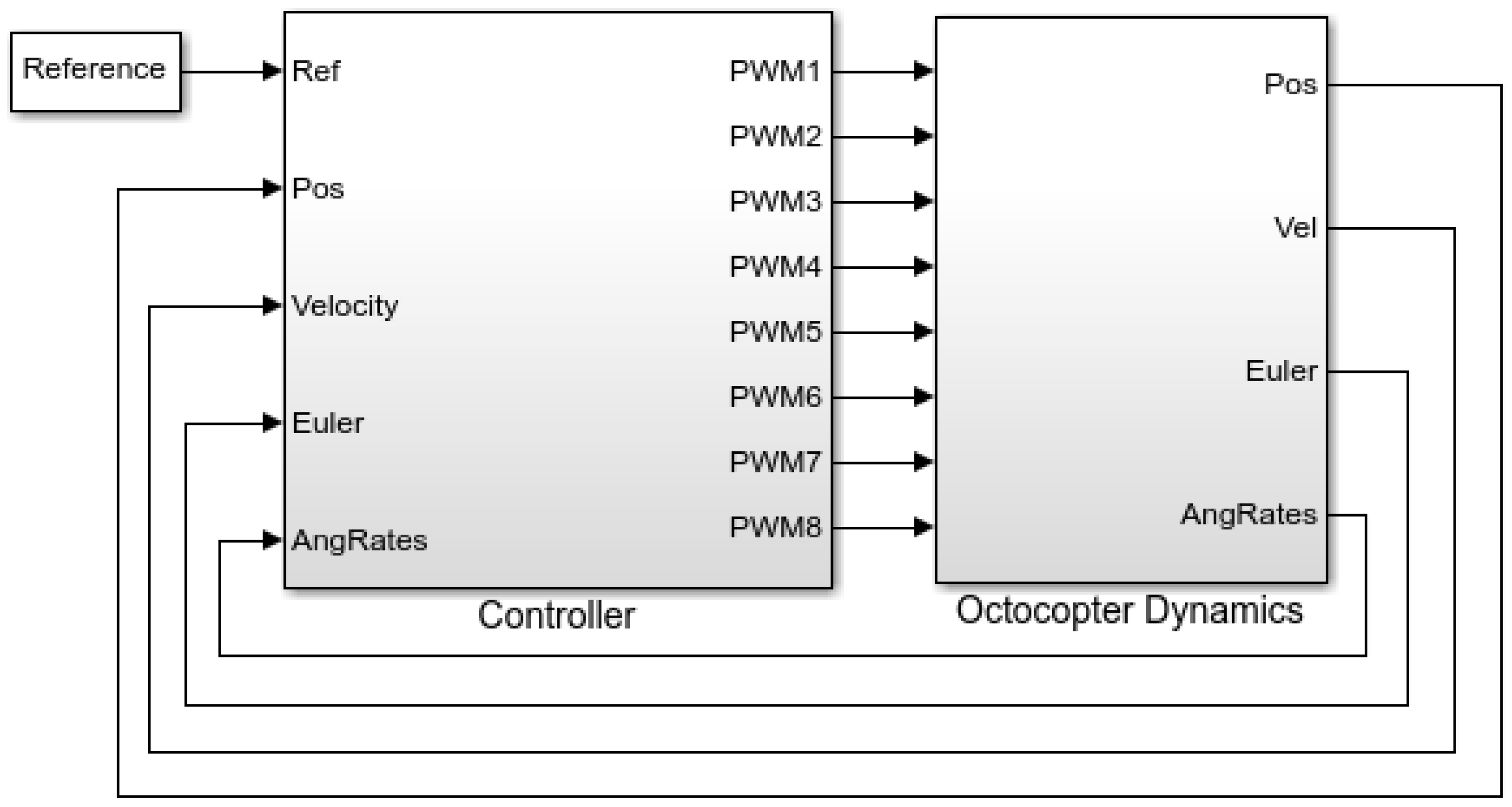
In order to design the controller that will be implemented in our vehicle, we built the theoretical model of the conventional frame derived from the last section within the Matlab Simulink environment to obtain the initial estimates of the controller gains that will be employed to fly the actual model. As depicted in Figure 2, the Simulink model structure comprises two main blocks. The controller block is responsible for generating the control signals necessary for directing the vehicle’s movements to the desired response, while the second block incorporates the octocopter’s motion dynamics, including rotor dynamics, inertial properties, aerodynamic interactions, battery and power modeling, environmental conditions, and external disturbances.
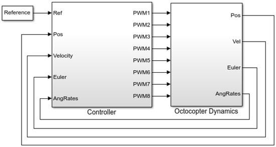
Figure 2.
Octocopter model in Simulink.
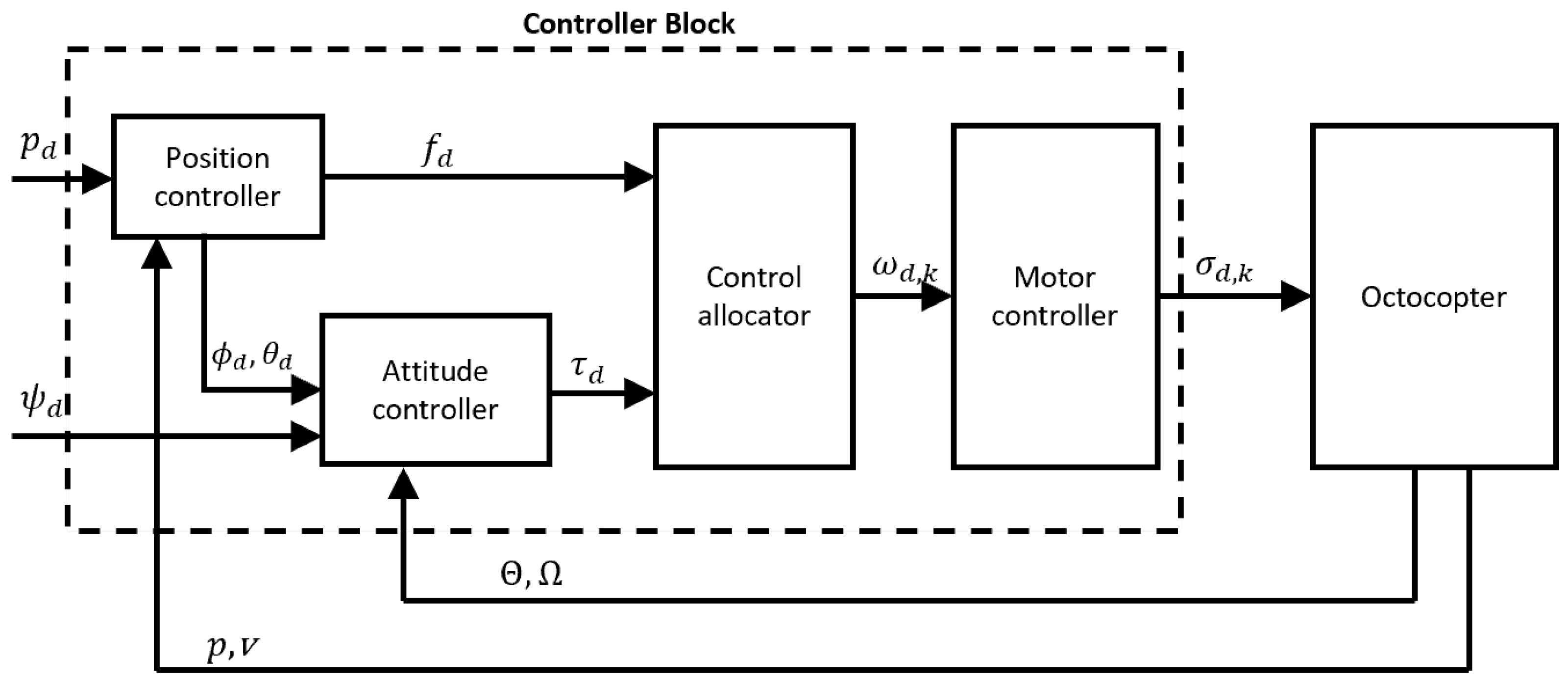
The control process has an essential role in the octocopter’s overall performance. It achieves the required characteristics, ensures flight stability, allows precise navigation and maneuvering, and guarantees the safety of the octocopter during flight operations through managing various aspects of the octocopter’s behavior, including its orientation, altitude, and speed. Our control architecture is designed based on a standard cascaded structure, including two control loops: the inner loop controls the model’s attitude, and its sampling time is five times faster than the outer loop, while the outer loop controls the aircraft’s position. As illustrated in Figure 3, we can categorize the controller structure into four distinct phases:
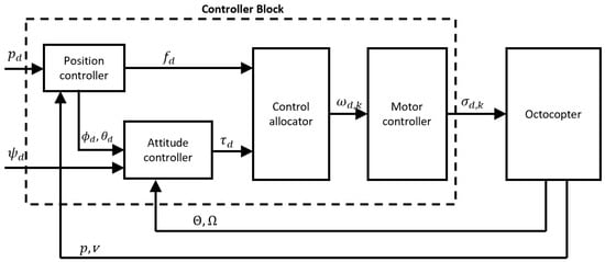
Figure 3.
Controller architecture for octocopter.
- Position control: In this phase, we determine the desired roll angle , pitch angle , and the total thrust based on the desired position .
- Attitude control: Here, we calculate the desired moment according to the desired attitude angles , , and .
- Control allocation: This phase involves converting the desired inputs ( and ) to equivalent propeller angular velocities (where k ranges from 1 to motor).
- Motor Control: It calculates the desired throttle command for each motor, based on for each k in the range of 1 to .
The proportional–integral–derivative (PID) controller is employed to control both the position and attitude of the octocopter. Attitude control is achieved by utilizing two nested loops: the outer loop is controlled by the proportional control of the angles [], while the inner loop employs PID control for the angular velocity []. The attitude control equations are expressed as follows:
The Simulink model that implements the control of the () state is shown in Figure 4, where the desired roll angle () is input from the position controller loop, and the output represents the torque sent directly to the control allocator. Similar models exist for pitch and yaw control.

Figure 4.
Roll state controller.
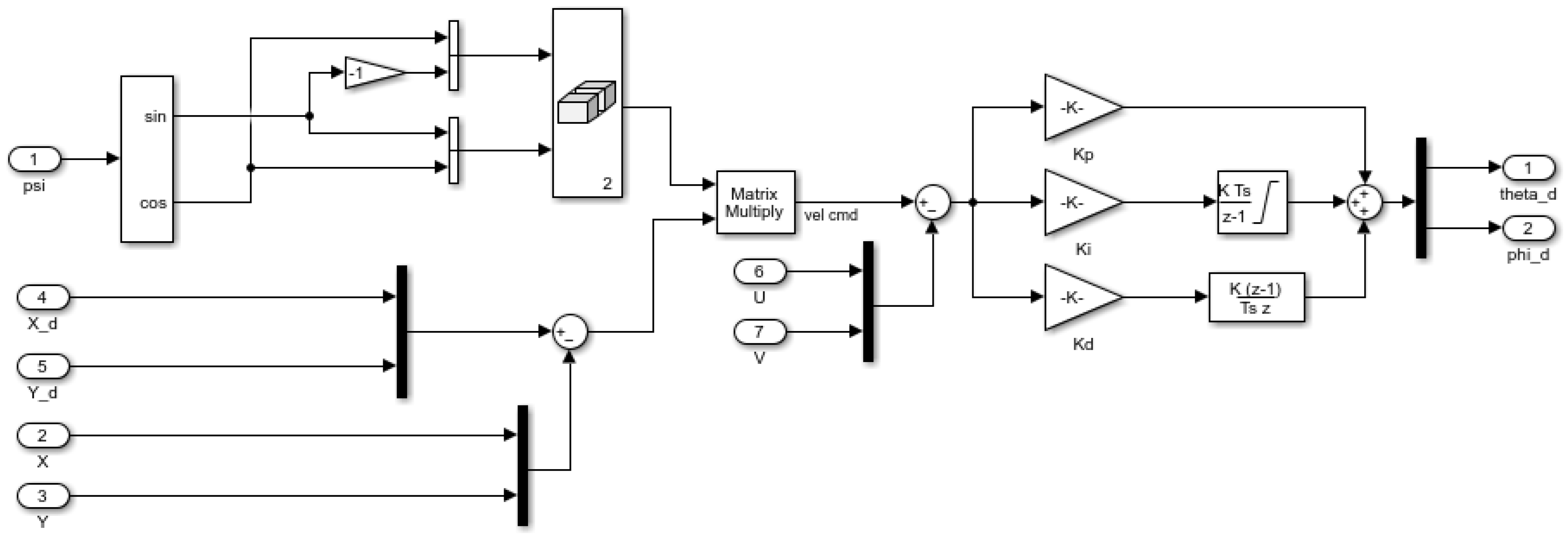
The position controller compromises two loops: an inner loop involves PID speed control for [], and an outer loop utilizes proportional control for displacement []. In the x and y states, the effect of yaw angle rotation () is incorporated. Additionally, in the z state, the octocopter is considered an offset added to the controller output to accurately control altitude.
The equations governing the position controller are as follows:
The Simulink model depicted in Figure 5 illustrates the controller for the states. The output of this controller represents the desired roll and pitch angles (, ) sent to the attitude control loop. For the z state, the model is similar but without the effect of , and its output represents the thrust force command sent to the control allocator.
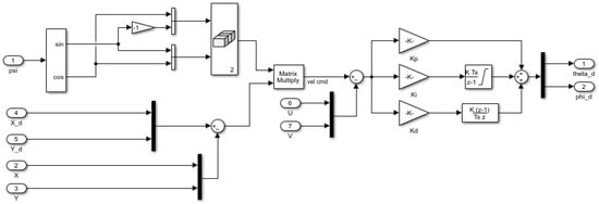
Figure 5.
Position state controller.
We conducted rigorous parameter tuning for these PID controllers using the MATLAB R2023a automated tuning tool to achieve optimal performance of the model. Tuning was performed sequentially, focusing initially on the inner loops with disregarding the effect of the outer loop. Once the inner loop tuning was completed, we moved to the outer loops. The simulation was carried out, and the model was subjected to extensive simulations within the Simulink environment to ensure the octocopter’s stability during different flight tests.
The controller gains obtained from the simulation are summarized in Table 1, providing insight into the specific parameters used to achieve desired control performance in our model.

Table 1.
Controller gains.
4. Methodology
In this section, we provide a comprehensive overview of the methodology employed to design, set up, and conduct flight tests with our novel two-layer octocopter model to gather essential data required for system identification. We begin by outlining the design and assembly process, including the integration of various components. Subsequently, we explain the approach used for data collection from the onboard sensors during flight tests.
4.1. Hardware Setup
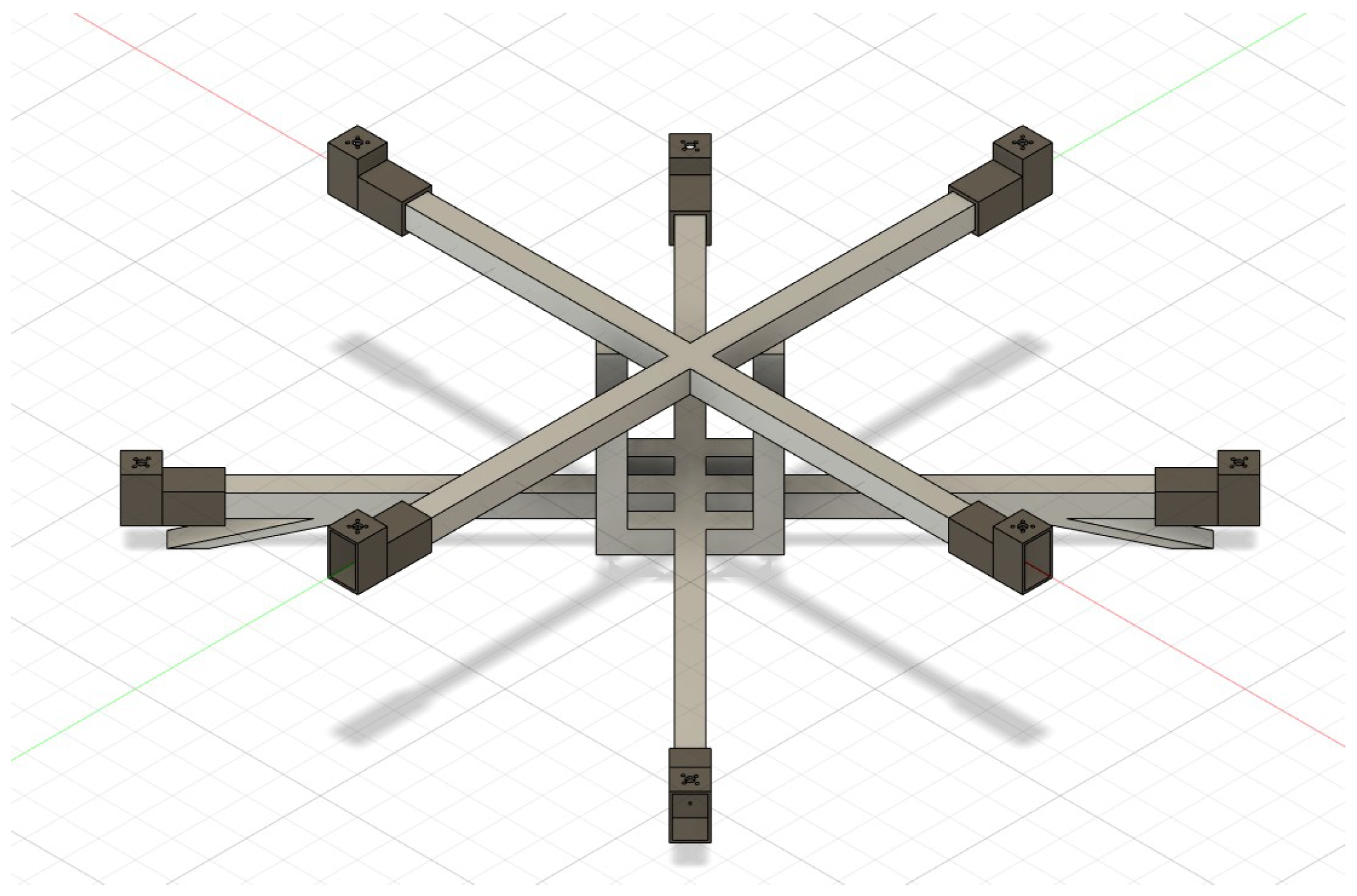
In this study, we employed a two-layer octocopter configuration with eight rotors arranged across two layers. The upper four rotors follow a (+) configuration, while the lower four are distributed in a (×) configuration. This design deviates from the conventional octocopter setup, where all eight rotors are aligned on a single plane. It is also distinct from the coaxial configuration, where each arm of the octocopter features two rotors, with one rotor positioned above the other. This novel two-layer design optimizes the spatial distribution, allowing for the integration of larger rotors, which in turn increases the drone’s capabilities [16]. The following Figure 6 demonstrates the CAD model of our octocopter model designed using Fusion 360 software.
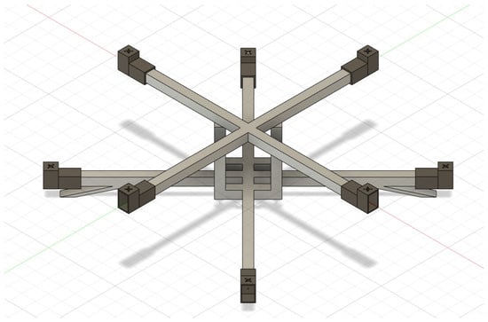
Figure 6.
Octocopter CAD model.
The physical dimensions and parameters obtained from the CAD model for our octocopter model are summarized in Table 2, providing insight into its structural characteristics and properties. These parameters are essential for the controller design and implementation phase.

Table 2.
Octocopter model parameters.
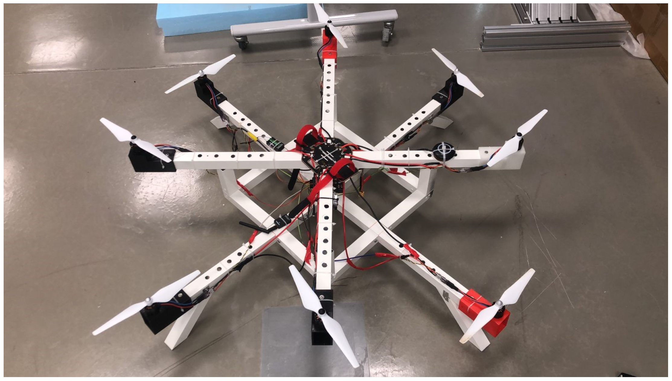
The final prototype of our octocopter demonstrated in Figure 7 highlights a robust design constructed using high-quality aluminum sheets to ensure both strength and lightness. In this prototype, rivets were used to create a stable and strong connection between the aluminum sheets. Moreover, custom rotor mounts were designed using Fusion360, and manufactured using a 3D printer. The utilization of 3D printing technology allowed the production of customized parts with critical parameters taken into account, such as weight and strength. Different filament colors were used to identify various aspects of the octocopter, such as the front (white) and the back (black). Different holes were drilled through the aluminum frame to reduce the overall weight. To assemble the octocopter, there are various important components that are needed. The required components are usually sold individually, and this is to allow for further customization of the multi-rotor drone design and specification. The following components are present in most multi-rotor drones:
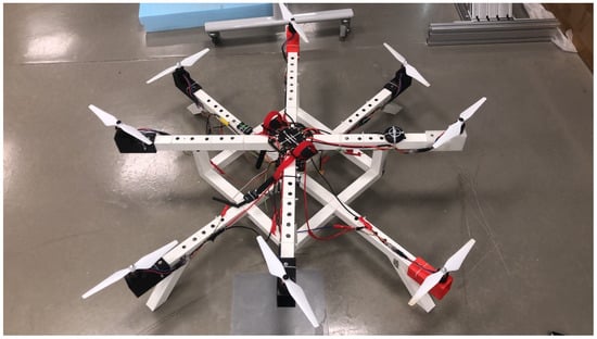
Figure 7.
Octocopter prototype.
- Fuselage: the frame where drone components are mounted, chosen for structural properties like strength, rigidity, and weight.
- Battery: main power source, commonly lithium polymer for high energy density.
- GPS: module for locating and automating drone flight by connecting to satellites.
- Telemetry: a device that allows real-time data transfer between the drone and the ground station.
- Propeller: a device that generates the thrust force by transforming rotational motion into linear motion.
- Rotor: considered to be the main propulsion system of the multi-rotor drone.
- Flight Controller: the drone’s “brain”, which processes signals from sensors such as a barometer, gyroscope, and GPS and remote controller, then sends output signals to actuators.
- Electronic Speed Controller (ESC): a device that regulates the rotor speed based on signals from the flight controller.
The following Table 3 lists the components that are used in the octocopter. As some components were designed and manufactured in the labs, such as the fuselage and the rotor mounts, these components are not mentioned in the table provided.

Table 3.
Components used in the model.
4.2. Data Collection
Collecting data during flight tests of the octocopter is an essential task in the system identification approach. To accomplish this, we utilized the Pixhawk flight controller to fly the model, which incorporates a wide range of sensors to detect real-time data that effectively capture the octocopter’s flight performance. These sensors include gyroscopes to measure the angular rates around roll, pitch, and yaw axes, while accelerometers are utilized to figure out the linear acceleration in the three-dimensional space. Magnetometers are employed to ascertain the orientation of the octocopter relative to the Earth’s magnetic field, which plays an indispensable role in providing the proper heading of the octocopter. To measure the altitude from the ground, barometers are integrated into the system. Finally, the global positioning system (GPS) is essential in assessing the octocopter’s precise location of the octocopter, enabling accurate navigation and real-time position tracking. All these sensors collaboratively provide insight into the octocopter’s flight behavior.
These collected data are subsequently employed in the state estimation process in which the Extended Kalman Filter (EKF) is applied to accurately estimate the octocopter’s states. The EKF, a sensor fusion technique well known for its accuracy in non-linear systems, integrates the data from these multiple sensors with the mathematical model of the octocopter’s dynamics to provide reliable and high-accuracy data for the octocopter’s essential states, including position, velocity, and orientation.
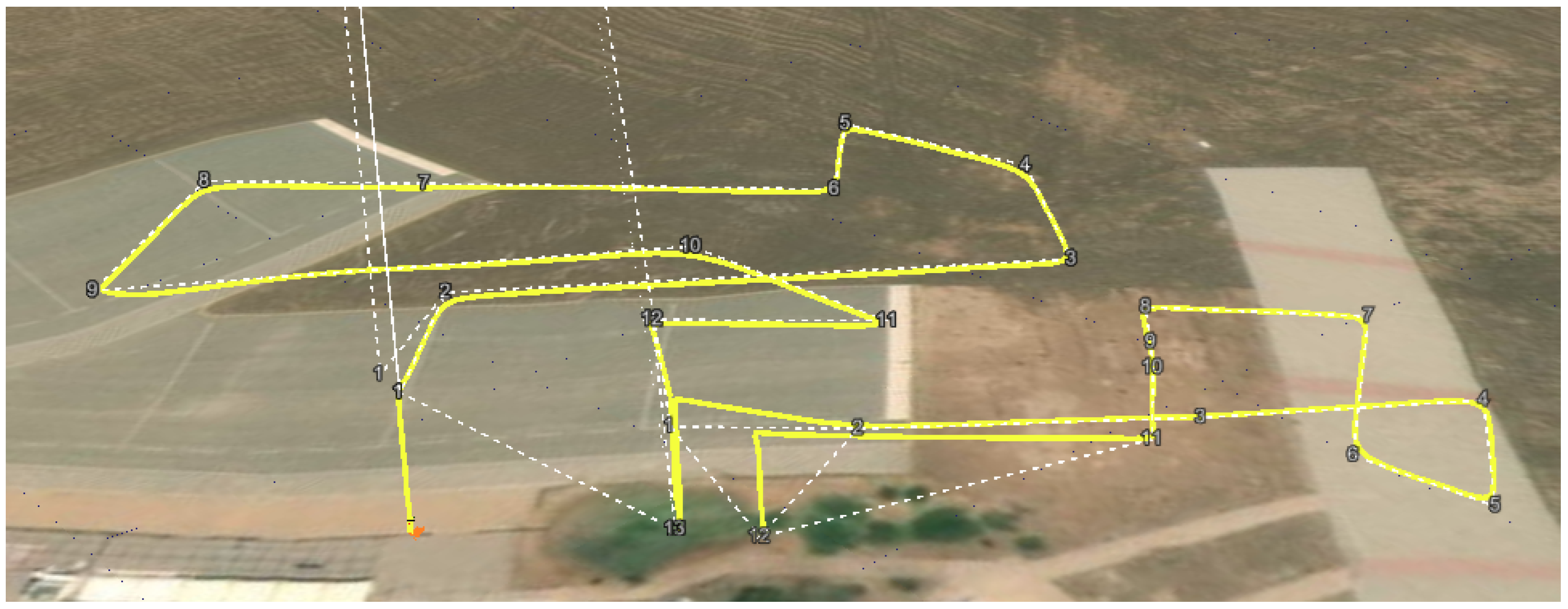
We conducted a series of outdoor flight tests as shown in Figure 8 to gather data that completely demonstrates the dynamic behaviors of our octocopter under various flight scenarios, allowing for the development of a system identification model that could accurately represent the octocopter’s model across a range of operating conditions.
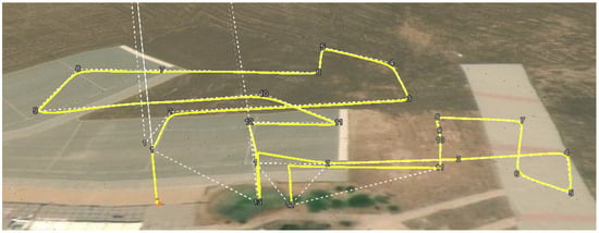
Figure 8.
Flight test scenario.
To simulate the real-world conditions and environmental effects, including wind variations, we strategically selected a set of target points in a three-dimensional space. These target points were positioned at varying locations and altitudes and at different times throughout the day. Figure 8 outlines an example of the flight mission scenarios that we designed to test the capabilities of the model and gather essential data for subsequent analysis and system identification. This approach allowed us to simulate the intricacies of real-world flight conditions, providing rich data for the identification process.
In our identification process, our primary focus is to identify the position and altitude states of the octocopter. Therefore, we recorded the (PWM) signals throughout flight tests, which represent the control inputs that regulate motor speed. Additionally, our data collection encompassed readings from accelerometer, barometer, and GPS sensors. Subsequently, this dataset was filtered using the Extended Kalman Filter (EKF) to yield the accurate three-dimensional location of the aircraft.
5. System Identification
System identification is a powerful method to develop dynamic models based on the experimental data gathered from both the control inputs and measured outputs of a system. This approach enables the derivation of an accurate model capable of capturing the inherent dynamical behavior of the system. In our context, we have a multi-input multi-output (MIMO) system with eight inputs that cannot be independently excited, as they are correlated through control allocation that allocates thrust and moment commands to angular velocities for the eight rotors. To address this, we employed the transfer function identification technique utilizing the prediction error method (PEM) to estimate the parameters of the transfer functions as explained in the following subsection.
5.1. Model Construction
As outlined in [30], consider the identification of a multiple-input multiple-output (MIMO) transfer function. The transfer function denotes the relationship between the j-th input and the i-th output of the system, represented as:
Here, m and n denote the orders of the numerator and denominator, respectively.
Our primary objective is to estimate the coefficients and to construct the most suitable model for the measured input–output data.
Let u and y represent the input and output of the system, respectively. We combine the historical data up to time N in the vector :
The prediction error method offers a systematic approach to estimate the parameters of a transfer function model that closely aligns with the observed system dynamics. This methodology can be summarized in the following steps:
- We describe the model as a predictor for the subsequent output, defined as:where denotes the posterior prediction of the output, and f represents the function linking the previous observed data.
- By introducing a finite-dimensional parameter vector , we parameterize this predictor as:
- To obtain as an estimate of from the model parameterization and the measured data vector , we minimize the model prediction error , defined as:where represents the variance between , and .
Considering a simple linear difference equation for the predictor model:
The predictor simplifies to:
We express the parameter vector as:
This representation allows us to rewrite the predictor as a linear combination of past inputs and outputs, facilitating the parameter estimation process.
Moving forward, we estimate the parameter as:
where the objective function is defined as:
Here, ℓ represents a loss function, e.g., .
Subsequently, we apply the Gauss–Newton iterative optimization method to obtain the parameter estimates . This iterative process involves the following:
- Initializing the parameter estimate and setting the iteration counter .
- Computing the predicted output values for all time steps based on the current parameter estimate .
- Calculating the gradient vector and the Hessian matrix to update the parameter estimate:
- Solving the linear system for the parameter update :
- Updating the parameter estimate:
- Checking for convergence or termination criteria and repeating the process until convergence is achieved.
Through this iterative optimization process, we iteratively update the parameters until convergence is achieved, ensuring an accurate representation of the system’s states.
To model the dynamics of the octocopter and identify the transfer function relating its x, y, and z states to the motor signals , we consider a multiple-input multiple-output (MIMO) transfer function representation. The transfer function for each state (x, y, z) will have its own set of coefficients corresponding to the inputs from the eight motors.
The model equations for each state (x, y, z) can be expressed as linear combinations of the past states and motor signals. For example, the equation for the x state might look like:
where we have the following:
- represents the x state at time t.
- are the coefficients of motor i corresponding to the past states.
- are the coefficients corresponding to the motor i signal.
- Similar equations can be formulated for the y and z states.
Hence, we can express the parameter vector as:
where n and m denote the number of poles and zeros, respectively.
Similarly, formulations for the parameter vectors and follow the same procedure. We implemented our approach using MATLAB software to efficiently handle the identification process mentioned earlier and extract the optimal values of the parameters . As a result, we effectively identified the transfer functions governing the dynamics of the x, y, and z states as detailed in Appendix A.
5.2. Model Validation
The model validation is an essential step that follows the model training. The Root Mean Square Error (RMSE) function is a commonly used performance measure in system identification that calculates the average squared differences between the measured and predicted outputs as expressed by the formula:
where represents the measured output of the system, is the predicted output, and N denotes the number of predicted data points.
6. Results and Discussion
In this section, we present the significant results that constitute the principal novelty contribution of our study. Although our study delved into various points, including the design process and material selection, the manufacturing process, the controller design, and the filtering of readings from onboard sensors, we are going to highlight the results obtained from identifying the transfer function governing the position and altitude states of the system.
The methodology employed to obtain these results is as follows: after the manufacturing of the octocopter model and tuning controller gains through the Simulink model, we utilized the Pixhawk, an open-source autopilot, to fly the model with the obtained controller gains. Using the mission planner software, we designed diverse missions in which the octocopter autonomously tracked predefined points on a map, each specified by longitude, latitude, and altitude. The selection of these points aims to collect a wide set of data representing various scenarios.
For the measured data, a sampling rate of 0.1 s was chosen to accurately capture position changes, based on GPS data fused with accelerometer and barometer readings. Simultaneously, PWM signals sent to the eight rotors were recorded. Through all flight tests, we collected rows of data containing inputs representing the eight PWM signals and three output signals representing position and altitude. Following data collection, we selected a set of flight test data and employed our approach to predict transfer functions that relate inputs to outputs. This process involved iterative optimization to determine the appropriate number of poles and zeros and their locations that accurately describe the model, ensuring high fit accuracy and low RMSE error. We then compared the identified model with other flight test data, iterating this process until obtaining a model that fit all collected flight test data. After completing our system identification procedure, we successfully identified the transfer functions outlined in Appendix A, which describe the translational dynamics of our innovative two-layer octocopter. These transfer functions, comprising five poles and three zeros, were carefully tuned to accurately reflect how the octocopter behaves under different conditions. The five poles in the transfer functions help the system handle various dynamic responses, such as those from the octocopter’s complex aerodynamics and motor actions. These poles are crucial for the stability and control of the UAV, as they determine how responsive the system is to changes in input. The three zeros, on the other hand, play a role in managing the system’s responses, helping to reduce any unwanted effects from specific frequencies. Additionally, analyzing these transfer functions helps us fine-tune our controller, ensuring the UAV performs well across different scenarios. Identifying these functions is a practical approach that significantly enhances how unmanned aerial systems operate in real situations. Our ability to predict the UAV behavior from just the control inputs and initial conditions distinguishes our research within the realm of UAV system dynamics.
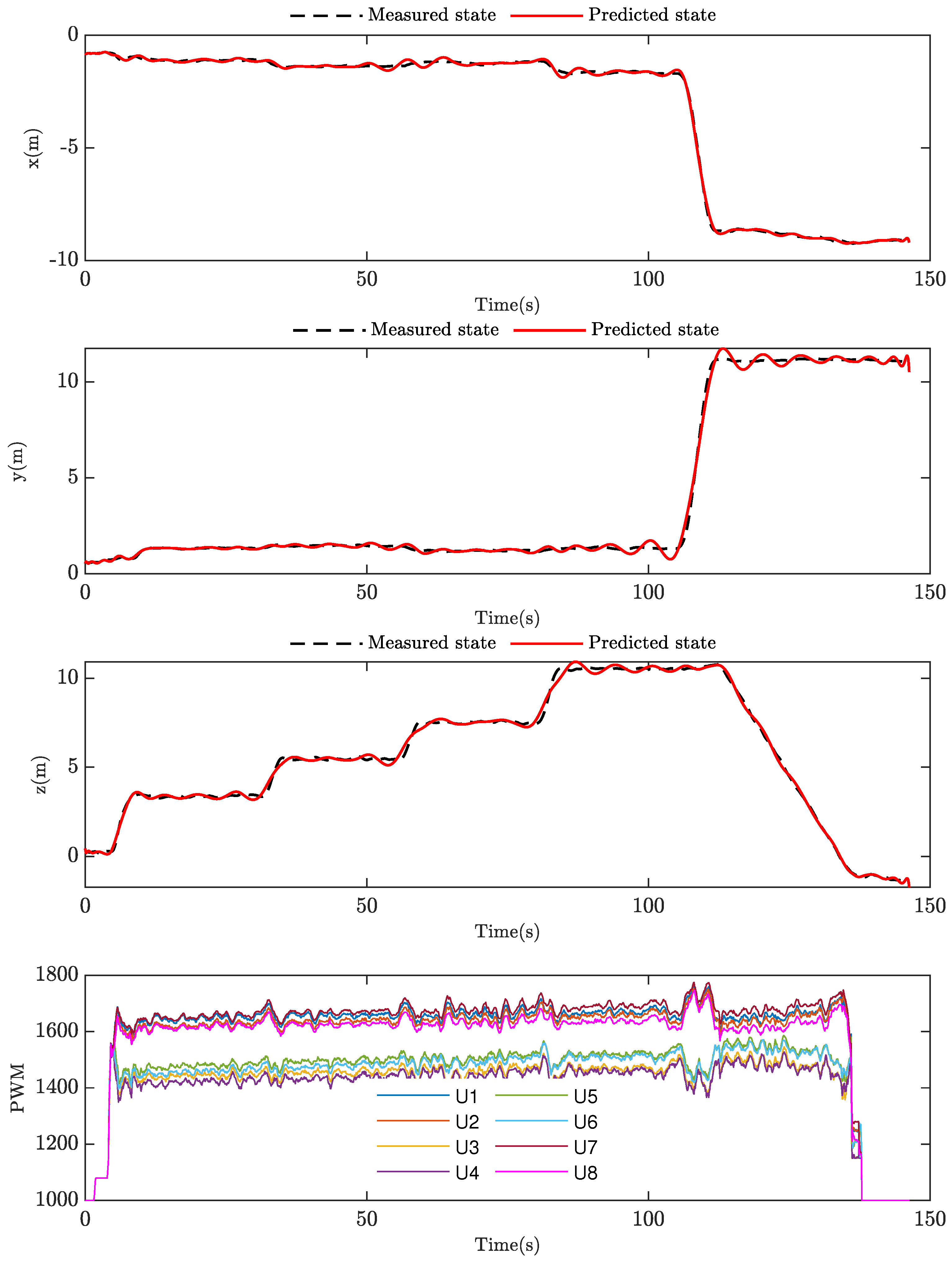
Figure 9 illustrates the comparison between the predicted output of our model for the three states of the octocopter and the corresponding measured data and also represents the PWM input signals corresponding to the eight rotors. In this flight test, we directed the octocopter to take off and reach different altitudes while maintaining the same location, followed by a relocation and landing at a different point from its takeoff site. It is worth highlighting that, considering the nature of the two layers, the lower level’s control action generates more thrust than the higher level’s, and there is nearly a coupling between each of the two rotors due to the model’s symmetry. As depicted in the figure, the model successfully predicted the three output states.
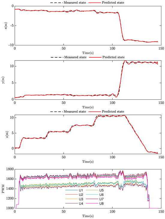
Figure 9.
Comparison between measured and predicted data.
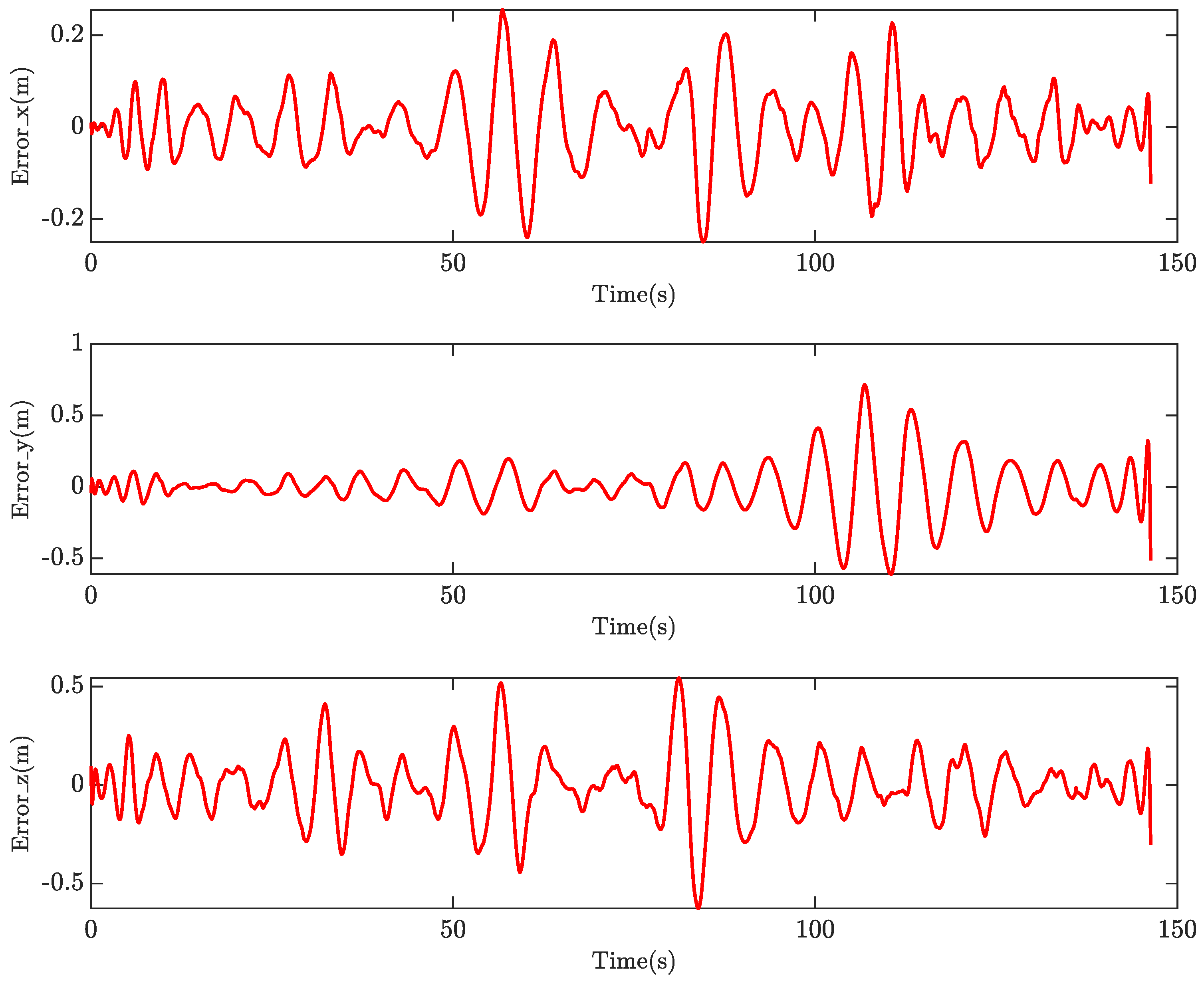
Figure 10 demonstrates the prediction error of these states, with the Root Mean Square Error (RMSE) that measures the average difference between the predicted and actual values calculated at for the x state, for the y state, and for the z state. This quantitative assessment highlights the high accuracy and reliability of our identified model in capturing the system’s dynamics and predicting the octocopter’s states with an average error not exceeding 10 cm.
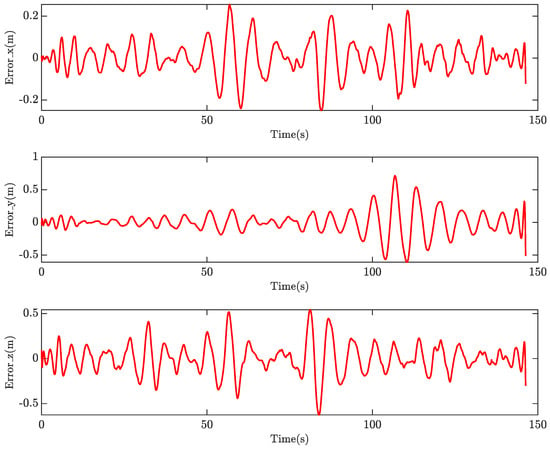
Figure 10.
Time history of the prediction error.
Our identified model underwent a validation phase consisting of nine distinct flight tests conducted in varying locations, altitudes, and at different times. This approach aimed to thoroughly assess the model’s performance under various real-world conditions, ensuring its robustness and reliability in different operational scenarios. During the validation process, we initialized the model with the initial states before flying, then provided inputs to the model and calculated the predicted states and the Root Mean Square Error (RMSE) between these predicted and measured data. The results of this extensive validation are summarized in Table 4 in terms of RMSE error in meters. These validation results demonstrate an impressive level of accuracy of our approach to predict the translational states of the system. Across all flight tests, the model consistently achieved an average error of m for x state, m for x state, and m for z state. The figures depicting these flight tests, along with their corresponding predicted responses, are included in Appendix A.

Table 4.
Validation results of the model.
The results from our model are promising, illustrating the potential of our approach in effectively identifying the transfer function governing the translational states of the octocopter, specifically when you have a challenging design. This step will lead to the design and analysis of more sophisticated controllers for this innovative configuration that offers a remarkable boost in thrust.
7. Conclusions
This paper presents the development and identification of the translational dynamics of a two-layer octocopter configuration. The primary achievement is the identification of transfer functions that directly relate the PWM inputs of the eight motors to the position and altitude states of the octocopter using the prediction error method (PEM). These transfer functions have been validated through various real-world flight tests under different environmental conditions, demonstrating remarkable accuracy with minimal RMSE error. A key advantage of our proposed system identification process is its straightforward methodology, which provides sequential steps, from the initial derivation of dynamical equations to the acquisition of transfer functions, that describe the octocopter’s motion in real-world conditions. This approach is versatile and can be extended to other multi-rotor configurations and even fixed-wing UAVs. Currently, we treat the model as a black box capable of predicting outputs from inputs without detailed analysis. Future investigations will focus on a detailed analysis of the identified transfer functions, their correlation with the physical model, and an investigation of response and stability characteristics. Overall, this research advances the understanding of UAV dynamics and offers a robust methodology for future UAV system identification efforts.
Author Contributions
Conceptualization, T.N.D. and M.M.K.; methodology, M.E. and R.K.; software, M.E.; validation, M.O. and S.K.A.; writing—original draft preparation, M.E. and R.K.; writing—review and editing, T.N.D. and M.M.K.; supervision, M.O.; project administration, S.K.A.; funding acquisition, T.N.D. All authors have read and agreed to the published version of the manuscript.
Funding
This research was funded by the United Arab Emirates University, grant number (12N098).
Data Availability Statement
The raw data supporting the conclusions of this article will be made available by the authors on request.
Conflicts of Interest
The authors declare no conflicts of interest.
Abbreviations
The following abbreviations are used in this manuscript:
| PEM | Prediction error method |
| UAV | Unmanned aerial vehicle |
| VTOL | Vertical take-off and landing vehicle |
| MIMO | Multi-input multi-output system |
| EKF | Extended Kalman Filter |
| RMSE | Root mean square error |
Appendix A
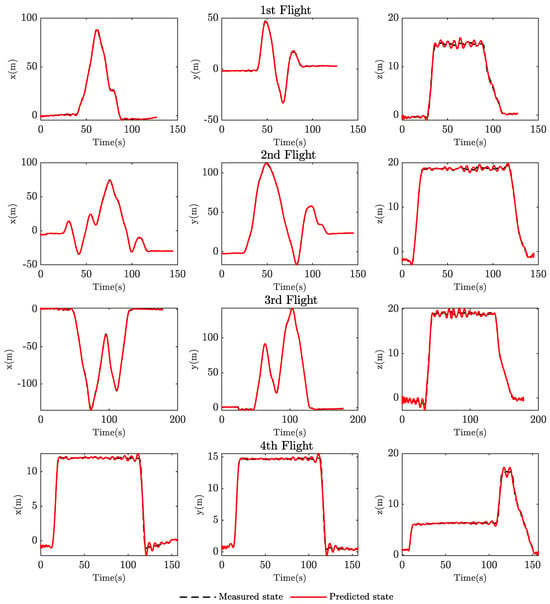
Figure A1.
Validation results of flight tests.
Figure A1.
Validation results of flight tests.
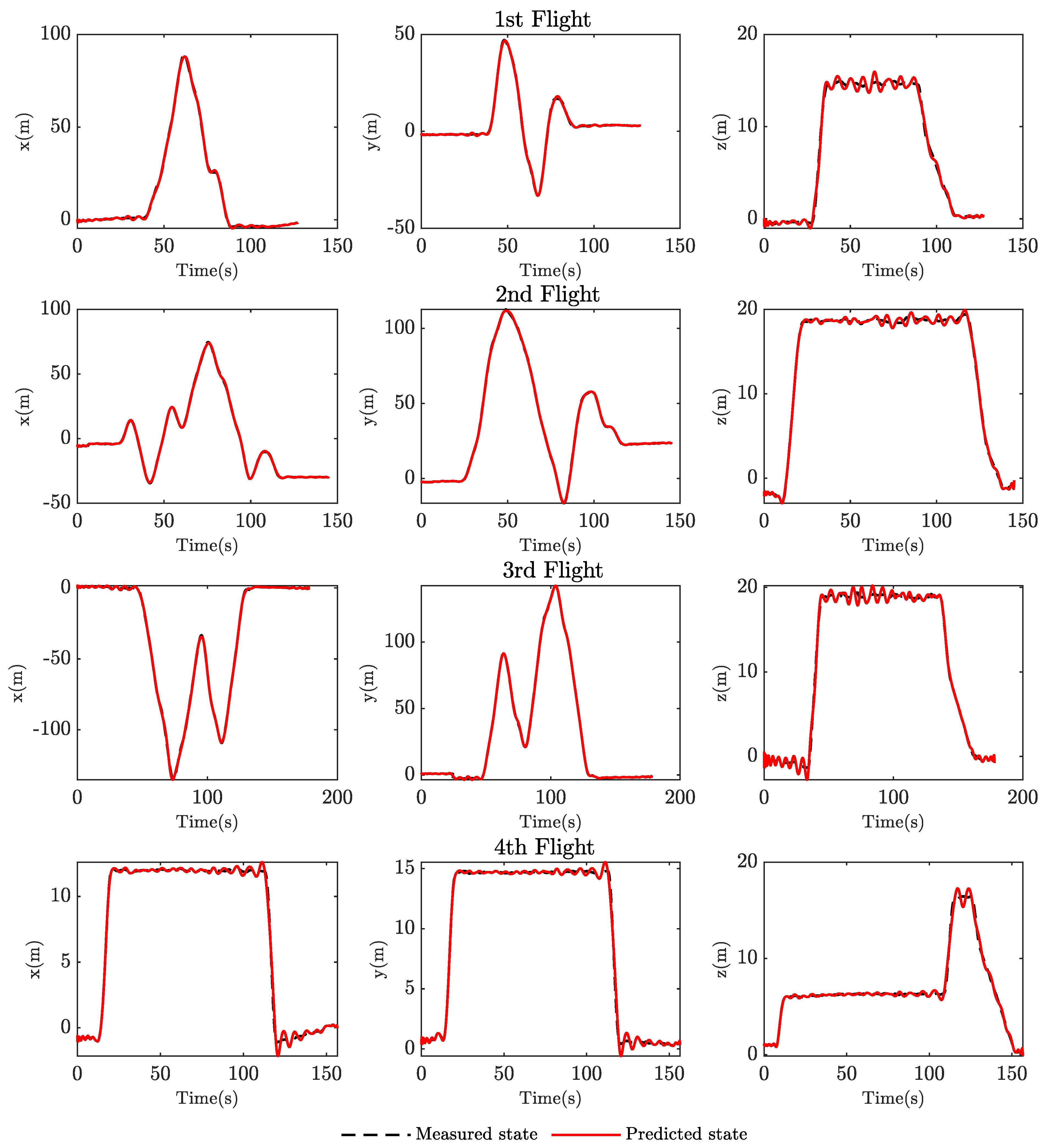
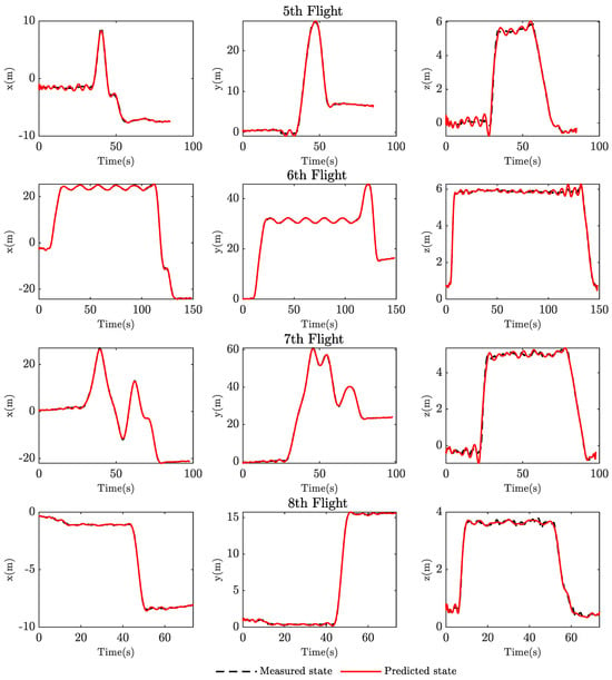
Figure A2.
Validation results of flight tests.
Figure A2.
Validation results of flight tests.
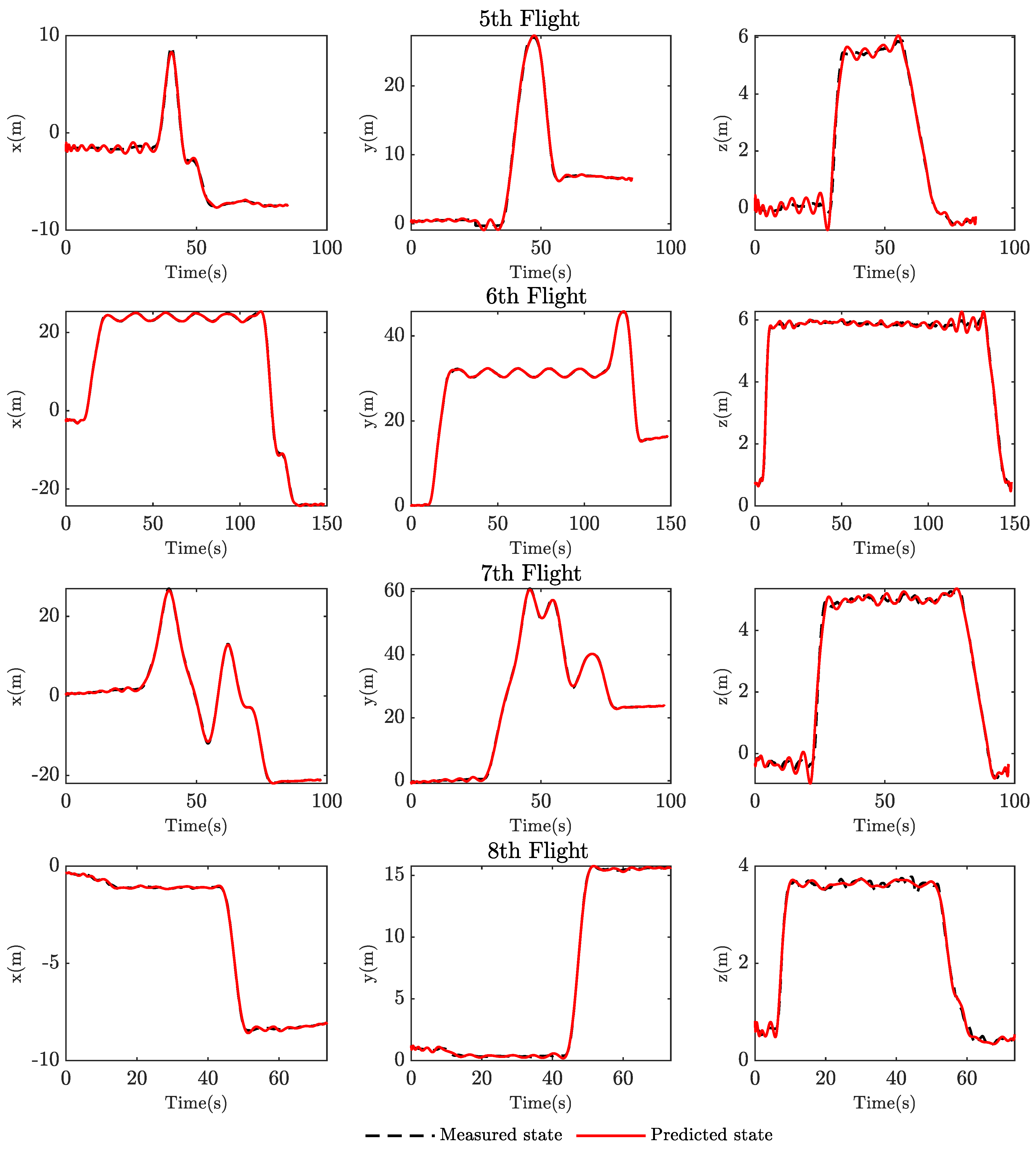

Table A1.
Identified transfer functions.
Table A1.
Identified transfer functions.
| State | x | y | z |
|---|---|---|---|
| U1 | |||
| U2 | |||
| U3 | |||
| U4 | |||
| U5 | |||
| U6 | |||
| U7 | |||
| U8 |
References
- Hassanalian, M.; Abdelkefi, A. Classifications, applications, and design challenges of drones: A review. Prog. Aerosp. Sci. 2017, 91, 99–131. [Google Scholar] [CrossRef]
- Dief, T.N.; Yoshida, S. System identification for quad-rotor parameters using neural network. Evergreen 2016, 3, 6–11. [Google Scholar] [CrossRef]
- Ahmed, F.; Mohanta, J.; Keshari, A.; Yadav, P.S. Recent advances in unmanned aerial vehicles: A review. Arab. J. Sci. Eng. 2022, 47, 7963–7984. [Google Scholar] [CrossRef] [PubMed]
- Dief, T.N.; Yoshida, S. System identification and adaptive control of mass-varying quad-rotor. Evergreen 2017, 4, 58–66. [Google Scholar] [CrossRef]
- Okasha, M.; Kralev, J.; Islam, M. Design and Experimental Comparison of PID, LQR and MPC Stabilizing Controllers for Parrot Mambo Mini-Drone. Aerospace 2022, 9, 298. [Google Scholar] [CrossRef]
- Yan, R.j.; Pang, S.; Sun, H.b.; Pang, Y.j. Development and missions of unmanned surface vehicle. J. Mar. Sci. Appl. 2010, 9, 451–457. [Google Scholar] [CrossRef]
- Dief, T.N.; Yoshida, S.; Abdelhady, M. Attitude and altitude stabilization of quad rotor using parameter estimation and self-tuning controller. In Proceedings of the AIAA Atmospheric Flight Mechanics Conference, Dallas, TX, USA, 22–26 June 2015; p. 2392. [Google Scholar]
- Saeed, A.S.; Younes, A.B.; Cai, C.; Cai, G. A survey of hybrid unmanned aerial vehicles. Prog. Aerosp. Sci. 2018, 98, 91–105. [Google Scholar] [CrossRef]
- Elhesasy, M.; Dief, T.N.; Atallah, M.; Okasha, M.; Kamra, M.M.; Yoshida, S.; Rushdi, M.A. Non-Linear Model Predictive Control Using CasADi Package for Trajectory Tracking of Quadrotor. Energies 2023, 16, 2143. [Google Scholar] [CrossRef]
- Osmic, N.; Tahirovic, A.; Lacevic, B. Octocopter Design: Modelling, Control and Motion Planning. arXiv 2022, arXiv:2212.01210. [Google Scholar]
- Weber, K.; Heweling, G.; Fischer, C.; Lange, M. The use of an octocopter UAV for the determination of air pollutants—A case study of the traffic induced pollution plume around a river bridge in Duesseldorf, Germany. Int. J. Educ. Learn. Syst. 2017, 2, 63–66. [Google Scholar]
- Zhang, B.; Tsuchiya, S.; Lim, H. Development of a lightweight octocopter drone for monitoring complex indoor environment. In Proceedings of the 2021 6th Asia-Pacific Conference on Intelligent Robot Systems (ACIRS), Tokyo, Japan, 16–18 July 2021; IEEE: Piscataway, NJ, USA, 2021; pp. 1–5. [Google Scholar]
- Gong, A.; Sanders, F.C.; Hess, R.A.; Tischler, M.B. System identification and full flight-envelope model stitching of a package-delivery octocopter. In Proceedings of the AIAA Scitech 2019 Forum, San Diego, CA, USA, 7–11 January 2019; p. 1076. [Google Scholar]
- Dixit, A.; Misra, A.; Talole, S. UDE based Sliding Mode Control for Octocopter. In Proceedings of the 2020 First IEEE International Conference on Measurement, Instrumentation, Control and Automation (ICMICA), Kurukshetra, India, 24–26 June 2020; IEEE: Piscataway, NJ, USA, 2020; pp. 1–6. [Google Scholar]
- Haddadi, S.J.; Zarafshan, P.; Dehghani, M. A coaxial quadrotor flying robot: Design, analysis and control implementation. Aerosp. Sci. Technol. 2022, 120, 107260. [Google Scholar] [CrossRef]
- Zhu, H.; Nie, H.; Zhang, L.; Wei, X.; Zhang, M. Design and assessment of octocopter drones with improved aerodynamic efficiency and performance. Aerosp. Sci. Technol. 2020, 106, 106206. [Google Scholar] [CrossRef]
- Zhang, X.; Li, X.; Wang, K.; Lu, Y. A survey of modelling and identification of quadrotor robot. Abstr. Appl. Anal. 2014, 2014, 320526. [Google Scholar] [CrossRef]
- Pairan, M.F.; Shamsudin, S.S.; Zulkafli, M.F. Neural Network Based System Identification for Quadcopter Dynamic Modelling: A Review. J. Adv. Mech. Eng. Appl. 2020, 1, 20–33. [Google Scholar]
- Ljung, L. Perspectives on system identification. Annu. Rev. Control 2010, 34, 1–12. [Google Scholar] [CrossRef]
- Sonntag, D. A Study of Quadrotor Modeling. Master’s Thesis, Linkopings Universitet, Linkoping, Sweden, 2011. [Google Scholar]
- Rehor, J.; Havlena, V. Grey-box model identification–control relevant approach. IFAC Proc. Vol. 2010, 43, 117–122. [Google Scholar] [CrossRef]
- Kantue, P.; Pedro, J.O. Grey-box modelling of an unmanned quadcopter during aggressive maneuvers. In Proceedings of the 2018 22nd International Conference on System Theory, Control and Computing (ICSTCC), Sinaia, Romania, 10–12 October 2018; IEEE: Piscataway, NJ, USA, 2018; pp. 640–645. [Google Scholar]
- Sun, S.; Schilder, R.; de Visser, C.C. Identification of quadrotor aerodynamic model from high speed flight data. In Proceedings of the 2018 AIAA Atmospheric Flight Mechanics Conference, Kissimmee, FL, USA, 8–12 January 2018. [Google Scholar]
- Worden, K.; Wong, C.; Parlitz, U.; Hornstein, A.; Engster, D.; Tjahjowidodo, T.; Al-Bender, F.; Rizos, D.; Fassois, S. Identification of pre-sliding and sliding friction dynamics: Grey box and black-box models. Mech. Syst. Signal Process. 2007, 21, 514–534. [Google Scholar] [CrossRef]
- Stanculeanu, I.; Borangiu, T. Quadrotor black-box system identification. World Acad. Sci. Eng. Technol. 2011, 5, 276–279. [Google Scholar]
- Osmić, N.; Kurić, M.; Petrović, I. Detailed octorotor modeling and PD control. In Proceedings of the 2016 IEEE International Conference on Systems, Man, and Cybernetics (SMC), Budapest, Hungary, 9–12 October 2016; IEEE: Piscataway, NJ, USA, 2016. [Google Scholar]
- Adir, V.; Stocia, A. Integral LQR control of a starshaped octorotor. Incas Bull. 2012, 4, 3–18. [Google Scholar]
- Kocijan, J. Modelling and Control of Dynamic Systems Using Gaussian Process Models; Springer: Berlin/Heidelberg, Germany, 2016. [Google Scholar]
- Tayebi, A.; McGilvray, S. Attitude stabilization of a VTOL quadrotor aircraft. IEEE Trans. Control. Syst. Technol. 2006, 14, 562–571. [Google Scholar] [CrossRef]
- Van Overschee, P.; De Moor, B. Subspace Identification for Linear Systems: Theory—Implementation—Applications; Springer Science & Business Media: Berlin, Germany, 2012. [Google Scholar]
Disclaimer/Publisher’s Note: The statements, opinions and data contained in all publications are solely those of the individual author(s) and contributor(s) and not of MDPI and/or the editor(s). MDPI and/or the editor(s) disclaim responsibility for any injury to people or property resulting from any ideas, methods, instructions or products referred to in the content. |
© 2024 by the authors. Licensee MDPI, Basel, Switzerland. This article is an open access article distributed under the terms and conditions of the Creative Commons Attribution (CC BY) license (https://creativecommons.org/licenses/by/4.0/).

