Article

Robust Multiple Unmanned Aerial Vehicle Network Design in a Dense Obstacle Environment

1
The School of Systems Science and Engineering, Sun Yat-Sen University, Guangzhou 510275, China
2
Defense Innovation Institute, Chinese Academy of Military Science, Beijing 100071, China
3
Intelligent Game and Decision Laboratory, Chinese Academy of Military Science, Beijing 100071, China
*
Authors to whom correspondence should be addressed.
Drones 2023, 7(8), 506; https://doi.org/10.3390/drones7080506
Submission received: 31 May 2023 / Revised: 19 July 2023 / Accepted: 21 July 2023 / Published: 2 August 2023

Abstract

:
Highly robust networks can resist attacks, as when some UAVs fail, the remaining UAVs can still transmit data to each other. In order to improve the robustness of a multi-UAV network, most methods construct the network by adjusting the positions of the UAVs and adding a large number of links. However, having a large number of links greatly consumes communication resources and increases serious signal interference. Therefore, it is necessary to study a method that can improve robustness and reduce the number of links. In this paper, we propose a method that consists of combining formation control and link selection, which can work in a distributed manner. For formation control, our method keeps the UAVs compact in the obstacle environment through an improved artificial potential field. The compact formation enables UAVs to have a large number of neighbors. For link selection, reinforcement learning is used to improve the robustness of the network and reduce the number of network edges. In the simulation of the 3D urban environment, three failure modes are used to verify the robustness of the network. The experimental results show that even if the number of links is reduced by 20 % , the networks designed by our method still have strong robustness.

1. Introduction

Multiple unmanned aerial vehicle (multi-UAV) communication networks are used for rescue missions, disaster monitoring and plant protection [1,2,3]. Limited by the communication range, each UAV can only establish links with neighbor nodes (UAVs within the communication range). Therefore, the multi-UAV communication network is a relay network, and the communication between UAVs at a long distance must be relayed by other UAVs [4]. However, UAVs may encounter failures. Once a large number of UAVs have failed, the network connectivity is greatly damaged. The robustness is used to measure the connectivity of the remaining network when some nodes fail [5]. A highly robust network can greatly reduce the impact of UAV failures. Even if a large number of UAVs fail, the connectivity of the remaining network can still be guaranteed.
In order to improve the robustness of the network, most methods adopt the approach of adjusting the positions of UAVs and enabling UAVs to connect with all of their neighbors [6,7]. Generally, the multi-UAV system can be represented as a multi-agent system. In order to adjust the positions of agents in various scenarios, a large number of formation control methods have been proposed [8]. For example, the author of [9] designed a method to control agents in a distributed manner. This work [10] enables agents to move with the desired velocity by using a virtual leader. A leader–follower formation control method [11] is designed to control agents under restricted conditions. Because the artificial potential field (APF) has the advantages of a simpler controller and fast response [12,13,14,15,16,17], it has been widely used in obstacle environments. However, networks obtained by these methods have a large number of edges, which increases the consumption of communication resources and the interference of signals. Therefore, it is necessary to design a method that can improve the robustness of the network and reduce the number of edges. In order to design this method, the following challenges need to be faced: (a) Because the positions of obstacles are unknown, a mathematical model is difficult to build in a dynamic environment. Appropriate links cannot be obtained. (b) A more compact formation can enable UAVs to establish enough links to ensure connectivity. An appropriate link selection strategy can reduce the impact of critical nodes on the network. However, the position is continuous, while the number of links is discrete. The joint optimization of position and edge is difficult to solve effectively. (c) For dense obstacles, the potential field easily makes UAVs move in the direction of more neighbors, which causes a large number of links to be disconnected and greatly destroys the robustness of the network.
To effectively solve the joint optimization problem with continuous and discrete variables, we divide the original problem into two sub-problems: formation control and link selection. In the formation control, an improved potential field is proposed to maintain a compact formation and avoid the excessive movement of UAVs in directions with more UAVs. The deep Q-network (DQN) is a deep reinforcement learning method and can explore high-quality strategies without accurately describing environments [18,19]. Therefore, for the link selection, DQN is used to select a small number of links for each UAV and improves the robustness of the network. The main contributions of this article are as follows.
  • Most methods focus on improving the robustness of the network in obstacle environments. The impact of link quantity is not considered. We propose a method that can reduce the number of links and ensure the robustness of the network.
  • The traditional artificial potential field cannot be adapted to dense obstacle environments. To solve the problem, we propose an improved artificial potential field to make UAVs more compact.
  • To realize distributed deployment, we design a reinforcement learning method base on centralized training and distributed execution. Well-trained reinforcement learning can be deployed to UAVs in a distributed manner.
  • In multiple failure modes, we deeply study the robustness of networks under different proportions of node failures and analyze the impact of attack modes on networks.
The remainder of this paper is organized as follows. In Section 2, the related work on robust networks is discussed. Section 3 states the problem of robust network optimization. The proposed method is introduced in Section 4. The experimental results and discussion are shown in Section 5. Section 6 presents the conclusion of this paper.

2. Related Works

To improve the robustness of networks, the existing methods can be divided into controller-based methods and optimal-design-based methods.
In the method based on controllers, most of methods guide UAVs to the desired positions by designing a controller, so that networks can be connected all the time. The early work in [20] combines APF with the virtual leader to maintain the connectivity of networks in unknown environments. Similarly, the method in [21] introduces a topology correction controller to maintain connectivity by modifying the topology of graphs. The method in [22] presents a connectivity maintenance control strategy based on control barrier functions. A method is proposed in [23], which can maintain robust connectivity while performing coverage tasks based on the Voronoi tessellation of an area of interest. The authors in [24] propose the informative path planning method under continuous connectivity constraints. In order to achieve more robust control, based on integral sliding-mode control and APF, the controller in [25] coordinates the velocity of the leader and the follower to maintain the connectivity of the communication network. Additionally, in the environment with obstacles, the method in [26] combines the APF with the distributed guidance law design to avoid collision and maintain connectivity. Considering the disturbances, the method in [27] uses APF and a neural network to improve the connectivity of the network. Under unmeasured velocities and unknown kinetics, the method in [28] introduces the output feedback control for cooperative formation to maintain connectivity and avoid obstacles.
In the method based on optimal design, networks are obtained based on the objective function of connectivity. For connectivity maintenance, the method in [29] presents a provably minimum connectivity maintenance framework to ensure the connectivity of the overall robot team. The method in [30] presents a method that can maintain global connectivity and implement a desired control strategy in an optimized fashion. The authors in [31] solve the problem of the spatial coverage of multiple tasks and ensure the global connectivity. The novel knowledge-incorporated policy framework in [32] is developed to efficiently cover multiple targets and maintain connectivity. A novel connectivity-aware multi-robot redistribution method is proposed in [33], which considers dynamic task allocation and connectivity for a heterogeneous robot team. Considering that the nodes are attacked, the method in [34] optimizes the positions of the helper nodes to maximize the robustness of the network. By iterative UAV positioning, the authors in [35] utilize biological robustness to design a reliable multi-UAV network, which can effectively reduce the impact of UAV failures.
Although these methods can improve network connectivity in various applications, they generate a large number of links, which increases communication resource consumption and signal interference between UAVs.

3. Problem Statement

As shown in Figure 1, in an obstacle environment, UAVs move to destinations. In order to transmit information to each other, it is necessary to establish appropriate links between UAVs.
For each UAV, the communication range is defined as r, and a UAV can only establish links with UAVs within the communication range r. The velocity of UAV i in the x-axis, y-axis and z-axis directions at time t is defined as vector v i ( t ) = ( v i , x ( t ) , v i , y ( t ) , v i , z ( t ) ) . The position of UAV i is defined as three-tuple o i ( t ) = ( o i , x ( t ) , o i , y ( t ) , o i , z ( t ) ) . Here, o i , x ( t ) , o i , y ( t ) , and o i , z ( t ) represents the position of UAV i in the x-direction, y-direction, and z-direction at time t, respectively. The unknown obstacles are represented as O b s = { o b s 1 , o b s 2 , · , o b s n } and n represents the number of obstacles. The o i , s is the starting position of UAV i, and o i , d is the destination position of UAV i. o i , s , x , o i , s , y , and o i , s , z are the starting position of UAV i on x, y, and z, respectively. o i , d , x , o i , d , y , and o i , d , z are the destination of UAV i on x, y, and z, respectively. D i s ( t ) is the distance matrix and represents the Euclidean distance among UAVs at time t. D i s ( k , j , t ) represents the Euclidean distance between UAV k and UAV j at time t. The neighbors of UAV i at time t are defined as N e b i ( t ) , which includes all UAVs within the communication range r of UAV i. The position of UAV i at the next time point is as follows in (1) and (2):
o i ( t + 1 ) = f s ( o i ( t ) , v i ( t ) , N e b i ( t ) )
subject to : 0 < v i ( t ) v m a x d ( o i ( t ) , N e b i ( t ) ) > s r d ( o i ( t ) , O b s ) ) > s r
In (1), f s ( · ) represents the flight strategy of UAV. In (2), · represents the norm of the vector. v m a x represents the upper limit of the velocity. d ( x , y ) represents the Euclidean distance between x, y, and d ( x , y ) > 0 . s r represents the safe distance between UAVs.
The multi-UAV communication network at time t is defined as an undirected graph G ( t ) = ( V ( t ) , E ( t ) ) . V ( t ) is the set of nodes and E ( t ) is the set of edges at time t, including all UAVs and all links, respectively. N is the number of nodes in the network. If there is an edge e i , j ( t ) E ( t ) between u i V and v j V , i j , the Euclidean distance between u i and v j must be lower than the coverage range r. A d j ( t ) is an adjacency matrix of the graph G ( t ) . If there is an edge between between u i V and v j , A d j ( i , j , t ) = 1 . Otherwise, A d j ( i , j , t ) = 0 .
We define D ( · ) as the failure mode. For example, some nodes are randomly deleted. To describe the robustness of the network after some UAVs fail, the number of nodes in the largest connected subset is used to measure the connectivity of the remaining network, and is recorded as L ( D ( G ( t ) ) ) . When some UAVs fail, the remaining network with a larger L ( D ( G ( t ) ) ) can ensure that more UAVs transmit information to each other. L ( D ( G ( t ) ) ) can be improved by increasing the number of links. However, having a large number of links increases the consumption of communication resources and signal interference between UAVs. Therefore, the design of the network aims not only to improve the robustness of the network, but also to reduce the number of edges. During the whole flight process, the optimization problem can be described as (3) and (4).
( A d j ( 1 ) ^ , A d j ( 2 ) ^ , , A d j ( T ) ^ ) = arg min t = 1 T s u m E d g e ( G ( t ) )
subject to : L ( G ( t ) ) > l b G ( t ) = ( O ( t ) , G * ( t 1 ) | π ) O t = f s ( O ( t 1 ) ) G ( t ) = D ( G ( t ) )
In (3), ( A d j ( 1 ) ^ , A d j ( 2 ) ^ , , A d j ( T ) ^ ) represents the optimal adjacency matrix at each time. s u m E d g e ( G ( t ) ) is the number of edges of network G ( t ) . In (4), O ( t ) is all positions of UAVs at time t. G * ( t 1 ) is the optimal network at time t 1 and G ( t ) is the remaining network. l b is the lower bound on the number of nodes in the largest connected subset. π ( · ) is the link selection strategy. To solve Equations (3) and (4), we need to jointly optimize the flight strategy and the link selection strategy. However, the flight strategy is a continuous optimization problem, and the link selection is a discrete optimization problem. This hybrid optimization problem is difficult to solve efficiently.

4. Proposed Method

4.1. Method Overview

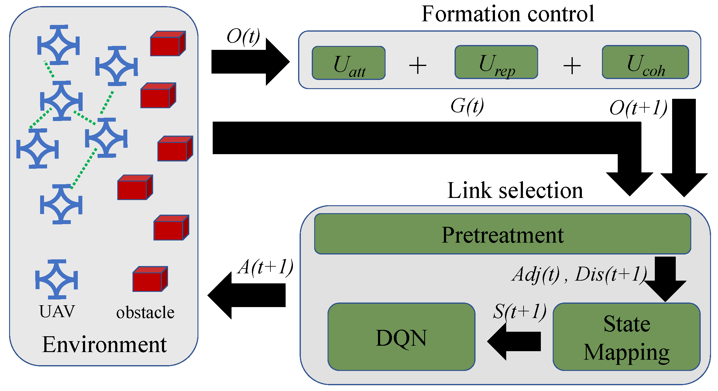
To effectively solve the joint optimization problems (3) and (4), a feasible solution is to divide them into multiple sub-problems and then solve them separately. Because the original Equations (3) and (4) involve the optimization of positions and links, we divided them into two sub-problems: formation control and link selection. The multi-UAV network is a relay network. If the formation is compact, UAVs can establish a large number of links with surrounding neighbors. When some UAVs fail, the remaining links can still ensure network connectivity. Therefore, the formation control needs to reduce the distance between UAVs under the constraint (2). If the number of links is small, the robustness of the network will decrease. Therefore, for link selection, an appropriate strategy needs to be designed to reduce the number of links while ensuring network robustness. The framework of our method is shown in Figure 2.
In the formation control, based on the positions of all UAVs O ( t ) , the positions of all UAVs at the next time point O ( t + 1 ) are obtained using the attractive potential field U a t t , the repulsive potential field U r e p , and the cohesive potential field U c o h . In the link selection, the pretreatment is used to obtain the adjacency matrix A d j ( t ) and the distance matrix D i s ( t + 1 ) based on the network G ( t ) and the obtained position O ( t + 1 ) . The state mapping is used to map the adjacency matrix A d j ( t ) and the distance matrix D i s ( t + 1 ) to the state S ( t + 1 ) . Through the state S ( t + 1 ) , the actions of all UAVs A ( t + 1 ) are obtained. After all UAVs perform actions, the adjacency matrix A d j ( t + 1 ) at time t + 1 can be generated, and the multi-UAV network at time t + 1 is obtained. The details of our method are as follows.

4.2. Formation Control

The robustness of the network can be improved by increasing links. In order to provide more links between UAVs in obstacle environments, three kinds of artificial potential fields are used to design the flight strategy, which includes the attractive potential field U a t t , the repulsive potential field U r e p , and the cohesive potential field U c o h . For any UAV i, these three potential fields can only act on UAVs within the communication range. The attractive potential field is used to guide UAVs to destinations. The repulsive potential field can ensure that UAVs do not collide with each other and with obstacles. The cohesive potential field makes UAVs form a compact formation. For UAV i, the total artificial potential field is formalized as (5).
U i ( t ) = α U a t t , i ( t ) + β U r e p , i ( t ) + η U c o h , i ( t )
α , β , and η are gain coefficients, and β α . The classical attractive potential field and repulsive potential field [36,37,38,39,40] are used to construct U i ( t ) . We define F a t t as an attractive force. F r e p is a repulsive force and F is the combined force of attraction and repulsion. Since the force is the directional derivative of the potential field, the force F i of UAV i can be expressed as (6).
F i ( t ) = α U a t t , i ( t ) + β U r e p , i ( t ) = α F a t t , i ( t ) + β F r e p , i ( t )
In (6), ∇ represents directional derivative operator. For UAV i, the attractive force F a t t , i ( t ) and the repulsive force F r e p , i ( t ) can be expressed as (7) and (8).
F a t t , i ( t ) = ( o i , d , x o i , x ( t ) ) i ( o i , d , y o i , y ( t ) ) j ( o i , d , z o i , z ( t ) ) k
F r e p , i ( t ) = j ( O b s N e b i ( t ) ) ( 1 d ( o i ( t ) , o j ) 1 s r ) ( 1 d ( o i ( t ) , o j ) ) 3 ( o i , x ( t ) o j , x ) i d ( o i ( t ) , o j ) < s r j ( O b s N e b i ( t ) ) ( 1 d ( o i ( t ) , o j ) 1 s r ) ( 1 d ( o i ( t ) , o j ) ) 3 ( o i , y ( t ) o j , y ) j d ( o i ( t ) , o j ) < s r j ( O b s N e b i ( t ) ) ( 1 d ( o i ( t ) , o j ) 1 s r ) ( 1 d ( o i ( t ) , o j ) ) 3 ( o i , z ( t ) o j , z ) k d ( o i ( t ) , o j ) < s r
In (7) and (8), i , i , and k are the directional vectors on x, y, and z, respectively.
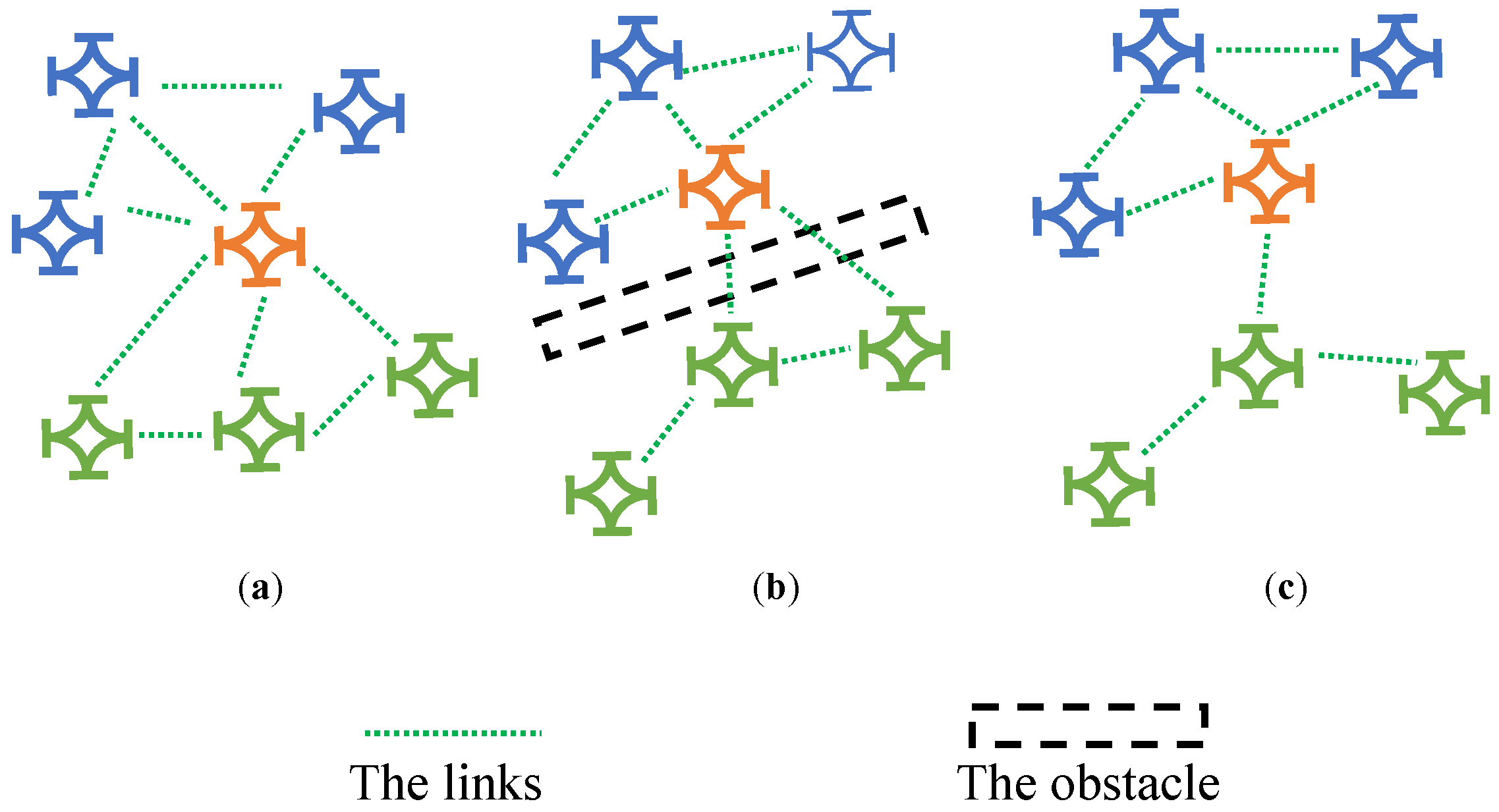
To make the formation compact, one feasible method is to make the UAVs move to the center position through the cohesive potential field [41]. However, in the scenes with dense obstacles, the cohesive potential field makes the distribution of UAVs uneven. It leads to a decline in the robustness of the network, as shown in Figure 3. In Figure 3a, limited by the communication range, no link can be established between blue UAVs and green UAVs, except for the orange UAV. In Figure 3b, to avoid obstacles, the orange UAV move upwards and exceeds the communication range of some green UAVs. In Figure 3c, after crossing obstacles, because there are far more blue UAVs than green UAVs within the communication range of the orange UAV, the combined force of blue UAVs on the orange UAV is much greater than that of green UAVs. Therefore, the orange UAV is closer to blue UAVs and exceeds the communication range of more green UAVs. The links between the orange UAV and green UAVs are significantly disconnected. This reduces the number of links in the network. Once a large number of UAVs fail, the remaining links cannot guarantee the robustness of the network.
To solve the problem of UAVs being overly concentrated in some directions, we propose an improved cohesive potential field, which is expressed as (9).
U c o h , i ( t ) = λ j N e b i ( t ) ( d ( o i ( t ) , o j ( t ) ) 3 O b j e c t i v e 1 l d ( o i ( t ) , o j ( t ) ) 2 O b j e c t i v e 2 ) d ( o i ( t ) , o j ( t ) ) r 0 d ( o i ( t ) , o j ( t ) ) > r
In (9), λ is a variable coefficient and λ = θ d ( o i ( t ) , o i , d ) d ( o i , s , o i , d ) . θ and l are gain coefficients. O b j e c t i v e 1 is used to reduce the distance between UAVs and make formation more compact. O b j e c t i v e 2 is used to prevent the excessive aggregation of UAVs. If the distance between UAVs is small, the reverse potential field will make UAVs to move in the opposite directions, and the distribution of UAVs will be more uniform. From (9), the cohesive force can be expressed as (10).
F c o h , i ( t ) = λ j N e b i ( t ) 3 ( d ( o i ( t ) , o j ( t ) ) 2 l ) Γ i ( t ) d ( o i ( t ) , o j ( t ) ) r 0 d ( o i ( t ) , o j ( t ) ) > r
In (10), Γ i ( t ) is the directional derivative of UAV i at time t and is recorded as (11).
Γ i ( t ) = ( o j , x ( t ) o i , x ( t ) ) i + ( o j , y ( t ) o i , y ( t ) ) j + ( o j , z ( t ) o i , z ( t ) ) k
The mechanism of the cohesive force is as follows: When the distance between UAVs is great, F c o h , i ( t ) makes UAVs approach quickly and maintain a compact formation. When the distance between UAVs is too close, the opposite potential field is generated by O b j e c t i v e 2 , and UAVs move in the opposite directions, so as to avoid UAVs moving to some directions excessively. Therefore, UAVs can still retain a large number of links in other directions.
In combination with (6) and (10), the total force can be formalized as (12).
F i ( t ) = α U a t t , i ( t ) + β U r e p , i ( t ) + η U c o h , i ( t ) = α f a t t , i ( t ) + β f r e p , i ( t ) + η f c o h , i ( t )
To obtain o i ( t + 1 ) , we obtain the current velocity v i ( t ) using the force F i ( t ) and add the velocity v i ( t ) to the current position o i ( t ) . Letting v i ( t ) = F i ( t ) , o i ( t + 1 ) can be expressed as (13).
o i ( t + 1 ) = o i ( t ) + F i ( t )
However, the maximum velocity of UAVs is limited. Therefore, we use v n o r m to adjust the velocity of UAV i and ensure that the modulus of v i ( t ) does not exceed the maximum velocity v m a x . Therefore, o i ( t + 1 ) can be transformed into (14).
o i ( t + 1 ) = o i ( t ) + v n o r m ( F i ( t ) )
In (14), if F i ( t ) v m a x , the velocity does not need to be adjusted and v n o r m ( F i ( t ) ) = F i ( t ) . If F i ( t ) > v m a x , the velocity must be adjusted and v n o r m ( F i ( t ) ) = v m a x F i ( t ) F i ( t ) .

4.3. Link Selection

DQN is a deep reinforcement learning method, which mainly consists of three components and can be expressed as < S ( t ) , A , R ( t ) > [42]. In our method, the state vector S ( t ) is composed of all states of UAVs at time t and recorded as S ( t ) = ( s 1 ( t ) , s 2 ( t ) , s i ( t ) , , s N ( t ) ) . s i ( t ) is the state of UAV i at time t and is an abstract representation of network structure and position information. A is the action space and recoded as A = ( a 1 , a 2 , a i , , a n ) , and n is the number of actions. a i , j ( t ) is the action of UAV i at time t and represents the fact that UAV i selects the action a j to establish links at time t. R ( t ) is the reward, which represents the rewards that can be obtained after all UAVs perform actions. The design of the three components is as follows.

4.3.1. State Design

In our scenario, UAVs need to work in a distributed manner. Therefore, each UAV should be deployed with DQN and these DQNs need to be trained jointly. However, joint training of multiple agents can lead to significant fluctuations in rewards and difficulty in convergence. To address this issue, the usual approach is to adopt the framework of centralized training and distributed deployment. In centralized training, we use the adjacency matrix A d j and distance matrix D i s to construct state S. The state S ( t + 1 ) is recorded as (15).
S ( t + 1 ) = R e l u ( A d j ( t ) D i s ( t + 1 ) W )
In (15), R e l u represents the activation function of the rectified linear unit. The symbol ∗ is matrix multiplication and W is the weight matrix of the neural network.
In distributed deployment, for UAV i, A d j i ( t ) is the adjacency matrix of UAV i at time t. N e b i ( t + 1 ) represents all neighbors of UAV i at time t + 1 . We define the second-order neighbor S e c N e b i ( t + 1 ) as the neighbor of all UAVs in N e b i ( t + 1 ) . S e c D i s i ( t + 1 ) is the distance matrix of the second-order neighbor S e c N e b i ( t ) . The state vector s i ( t + 1 ) is composed of the adjacency matrix A d j i ( t ) and the second distance matrix S e c D i s i ( t + 1 ) , and can be expressed as (16).
s i ( t + 1 ) = R e l u ( A d j i ( t ) S e c D i s i ( t + 1 ) W )
subject to : A d j i ( k , j , t ) = A d j ( k , j , t ) , k = i A d j i ( k , j , t ) = 0 k i S e c D i s i ( k , j , t + 1 ) = D i s ( k , j , t + 1 ) k S e c N e b i ( t + 1 ) S e c D i s i ( k , j , t + 1 ) = 0 k S e c N e b i ( t + 1 )
For DQN, the same state can be mapped to the consistent action. Therefore, in order to enable the centralized training model to be deployed in a distributed manner, the state of UAVs in a distributed manner should be the same as that of UAVs in a centralized manner. We can explain that for any UAV i, the states obtained by the (16) and (17) are consistent with those of (15).
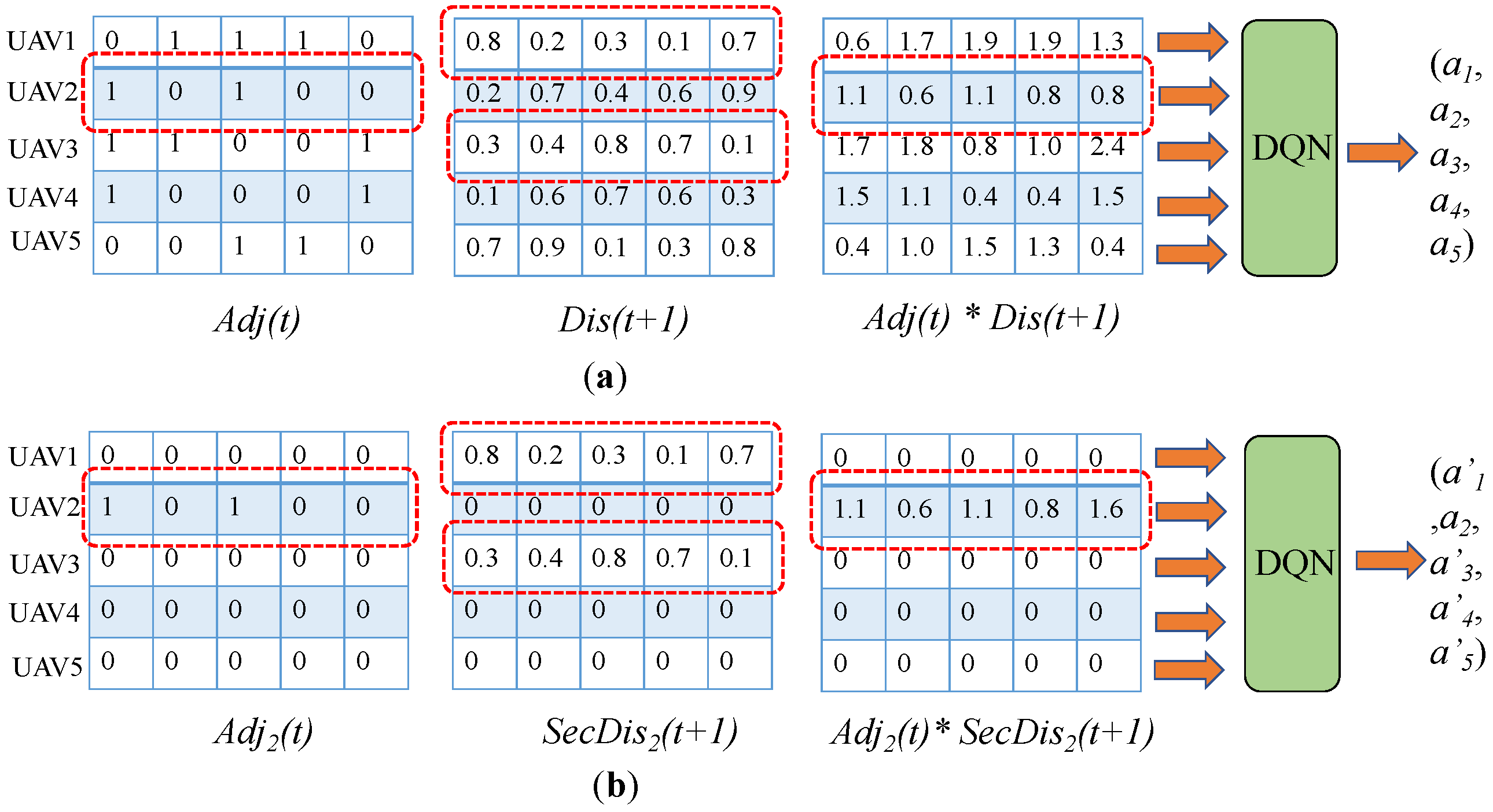
For a multi-UAV network composed of five UAVs, the computational process from state to action is shown as Figure 4. For UAV2, the neighbors are UAV1 and UAV3. In distance matrix D i s ( t + 1 ) , the vector of UAV1 v 1 is ( 0.8 , 0.2 , 0.3 , 0.1 , 0.7 ) , and the vector of UAV3 v 3 is ( 0.3 , 0.4 , 0.8 , 0.7 , 0.1 ) . Therefore, the second-order distance matrix of UAV2 S e c D i s 2 ( t + 1 ) only contains v 1 and v 3 . Furthermore, from Figure 4a,b, it can be seen that for UAV2, the results of A d j ( t ) multiplied by D i s ( t + 1 ) and A d j 2 ( t ) multiplied by S e c D i s 2 ( t + 1 ) are the same. Therefore, the state of UAV2 in a distributed manner is the same as that of UAV in a centralized manner, and the same action can be obtained. For any UAV i, the calculation process from state to action is the same as UAV2. Therefore, in a distributed manner, the proposed state mapping can effectively ensure that UAVs can obtain the same actions as in the centralized manner.

4.3.2. Action Design

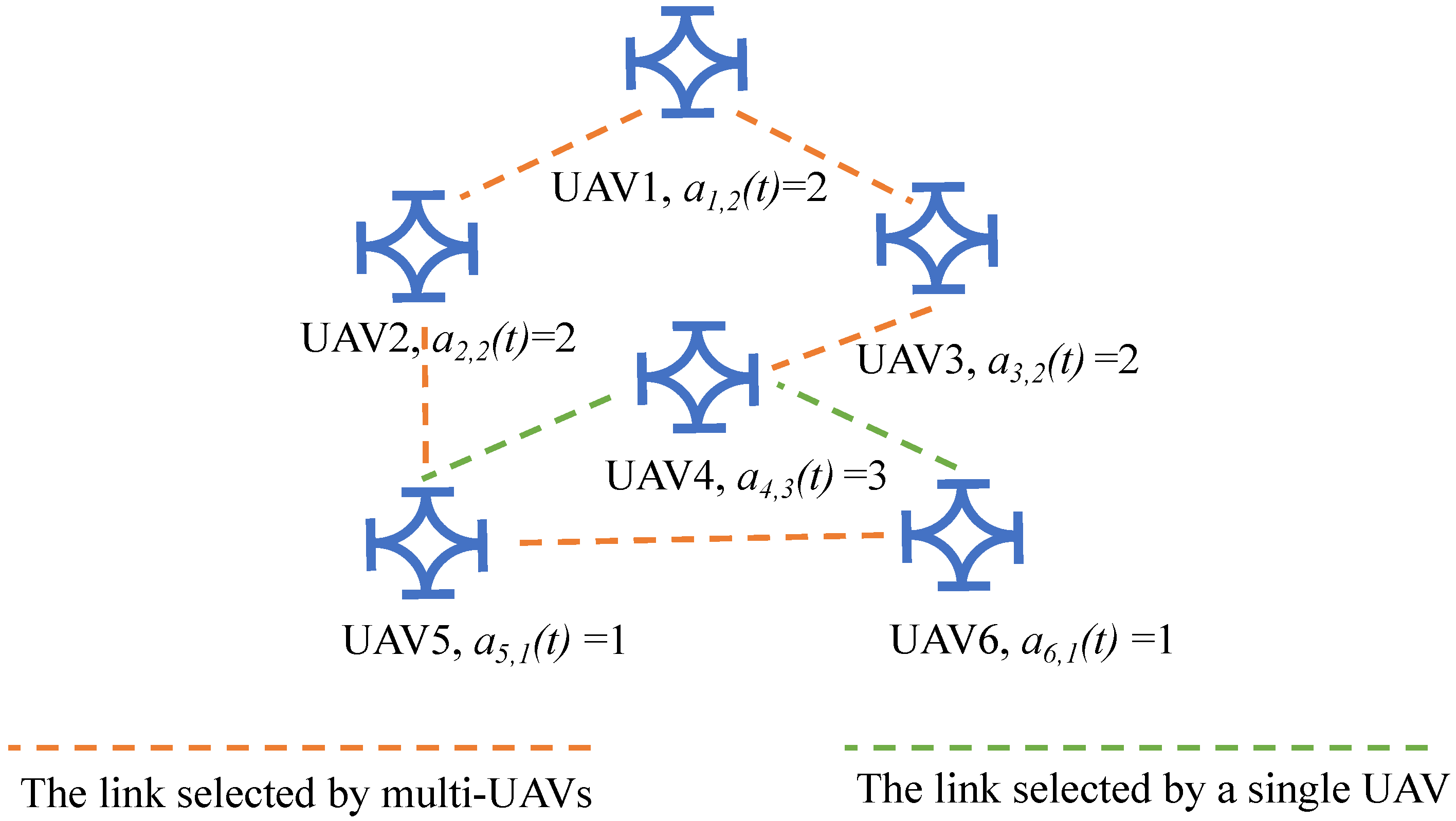
The action space A represents all modes of connection. a i , j ( t ) represents that the action a j selected by UAV i at time t and a j A . In order to reduce the scale of action space, the random strategy is used. Because the number of neighbors does not exceed N and at least one neighbor needs to be connected, the value range of a i , j ( t ) can be expressed as [ 1 , N ] . For a multi-UAV network with six UAVs, the network is shown in Figure 5.
The rules for constructing the network are as follows: (i) All UAVs randomly select neighbors to establish links. (ii) For any UAV i, if there is already a link between UAV i and UAV j, then the link established by i to j is ignored. For example, the action of UAV1 is a 1 , 2 ( t ) = 2 , and UAV1 randomly selects UAV2 and UAV3 to establish links. The action of UAV2 is a 2 , 2 ( t ) = 2 , and UAV2 randomly selects UAV1 and UAV5 to establish links. Because UAV1 has already established a link with UAV2, the link established from UAV2 to UAV1 is redundant. According to (ii), if the link between two UAVs is established, subsequent links are ignored. Therefore, only one edge is preserved between UAV1 and UAV2. Similar to UAV1 and UAV2, after applying rules (i) and (ii) to all UAVs, the network shown in Figure 5 can be formed.

4.3.3. Reward Design

The reward R ( t ) represents the rewards obtained after performing actions in A at time t. In the reward function, we need to consider the robustness and the number of edges. Since the framework of centralized training is adopted, the adjacency matrix and the neighbors of all UAVs can be obtained. In our method, the reward function can be formalized as (18) and (19).
R ( t ) = 1 ( s u m ( A d j ( t ) ) S N ( t ) ) 2 O b j e c t i v e 3 + s u m ( A d j ( t ) ) S N ( t ) O b j e c t i v e 4 + P L ( t )
subject to : P L ( t ) = 0 L ( A d j ( t ) ) > 0 . P L ( t ) = 2 L ( A d j ( t ) ) = 0
In (18) and (19), s u m ( A d j ( t ) ) represents the sum of all entries in matrix A d j ( t ) , and S N ( t ) is the sum of the number of neighbors of all UAVs. L ( A d j ( t ) ) represents the second small eigenvalue of the Laplace matrix of A d j ( t ) . If a network is connected, L ( A d j ( t ) ) is greater than 0. For (18) and (19), as the number of edges decreases, O b j e c t i v e 3 increases and higher rewards can be obtained. Therefore, O b j e c t i v e 3 makes the algorithm select actions that generate fewer edges. According to algebraic connectivity theory [43], with an increase in the number of edges, the robustness of the network becomes stronger. Therefore, O b j e c t i v e 4 is used to improve the robustness of the network. P L ( t ) is a penalty term. It can make DQN avoid the action of making the network disconnected.

5. Numerical Simulation

In the simulation, there are 32 UAVs in total, and UAVs move in the 3D urban environment with dense buildings. The size of the urban environment is 50 m × 50 m × 30 m. The starting positions of UAVs and the positions of obstacles are randomly generated in each experiment. The simulation duration is 200 steps. The parameters of our method are shown in Table 1. The flight process of UAVs in the urban environment is shown in Figure 6.
From Figure 6a, it can be seen that at the beginning, UAVs gathered together. At time 20, in order to avoid obstacles, the formation of UAVs is no longer compact. UAVs fly to their destinations in a dispersed form, as shown in Figure 6b. At time 200, UAVs arrived at their destinations, as shown in Figure 6c. From the trajectories of Figure 6d–f, it can be seen that UAVs can reach their destinations. It can also be seen that if there are no obstacles, the distance between UAVs is relatively small. If there are dense obstacles, the distance between UAVs increases. This means that the formation of UAVs can be adaptively changed according to the environment.
To further validate the effectiveness of our method, we verify the convergence of reinforcement learning and the ability of the flight strategy to maintain a compact formation in dense obstacle environments. In addition, the connectivity of the remaining network is also verified when some nodes fail. For the comparison method, method 1 includes the attractive force and the repulsive force, and each node establishes edges with all neighbors. Method 2 adds the cohesive force based on method 1. The scale-free network has good robustness and has been used to optimize network structure [44]. Therefore, for method 3, the attractive force, the repulsive force and the scale-free network are used to optimize networks. To avoid the influence of randomness, for all validation experiments, five experiments are performed.

5.1. Verification of Flight Strategy

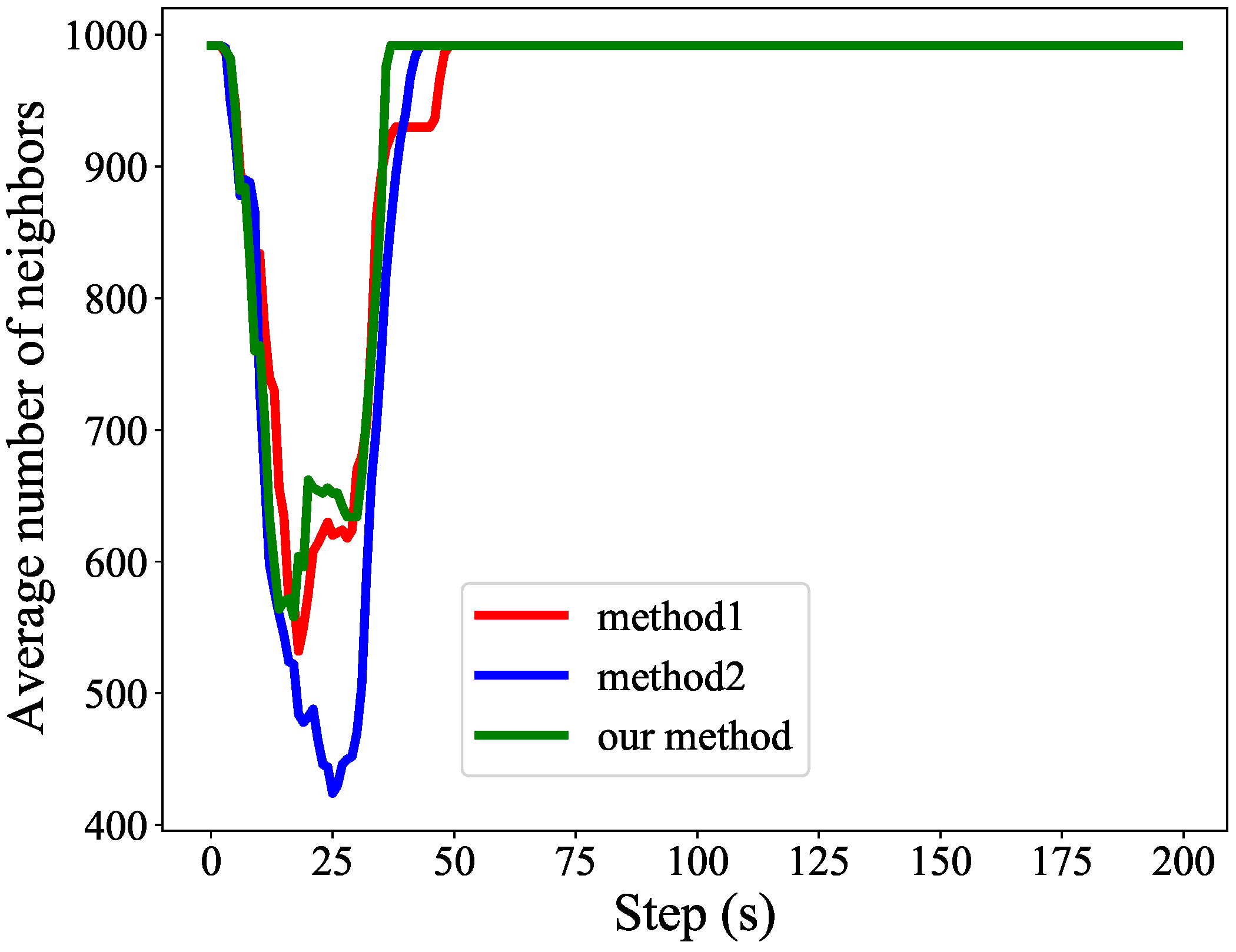
The flight strategy is used to make the formation of UAVs more compact. If the formation is more compact, UAVs will have more neighbors. Therefore, we evaluate the flight strategy using the average number of neighbors of all UAVs. The experimental results are shown in Figure 7.
From Figure 7, it can be seen that compared with method 2, the networks optimized through method 1 have more neighbors, and the networks optimized using our method have the highest number of neighbors. The reasons for the experimental results are as follows. When UAVs encounter obstacles, to avoid obstacles, UAVs move to different directions under the influence of the repulsive force, and the distribution of UAVs becomes uneven. In method 2, influenced by the cohesive force and the uneven distribution of positions, UAVs move to directions with more neighbors. Due to a limited communication range, the number of neighbors in other directions is decreased. Therefore, the average number of neighbors generated by method 2 is less than that of method 1. In our method, we use the improved cohesion to control formation. At the beginning, the distance between UAVs is large, and UAVs can gather quickly through improved cohesion. When UAVs excessively concentrate in the direction of more neighbors, the improved cohesion force will generate the reverse force. UAVs will move in the opposite directions and the number of neighbors in other directions will not be reduced.
We use the shortest distance between UAVs to verify the effectiveness of collision avoidance. The experimental results are shown in Figure 8.
The safe distance of UAVs is set to 0.1. From Figure 8, it can be seen that method 1 cannot maintain a safe distance between UAVs. Method 2 is stronger than method 1, but the safe distance is still short. Our method can maintain a large safe distance between UAVs, which enhances safety. The reasons for the experimental results are as follows. For method 1, in scenes with dense buildings, UAVs need to pass through narrow areas. The narrow areas make UAVs crowd together, and the repulsive force struggles to push away surrounding UAVs. Therefore, method 1 cannot guarantee a safe distance between UAVs. Affected by the cohesive force, UAVs dispersedly concentrate in directions with more neighbors. The formation of UAVs is looser. Therefore, compared to method 1, method 2 can make the shortest distance larger. Our method utilizes the improved cohesion. If the distance is less than a certain range, UAVs will use the reverse force to push away surrounding UAVs. Therefore, our method can effectively ensure the safety of UAVs.
Although our method can maintain a safe distance for UAVs, UAVs oscillate around the desired distance. The oscillation causes UAVs to be unable to stabilize in their optimal positions. The reasons for this result are as follows. When UAVs are near the desired distance, the proposed cohesion constantly switches between attraction and repulsion. This prevents UAVs from reaching balanced states. Therefore, the positions of UAVs keep oscillating.

5.2. Verification of Convergence

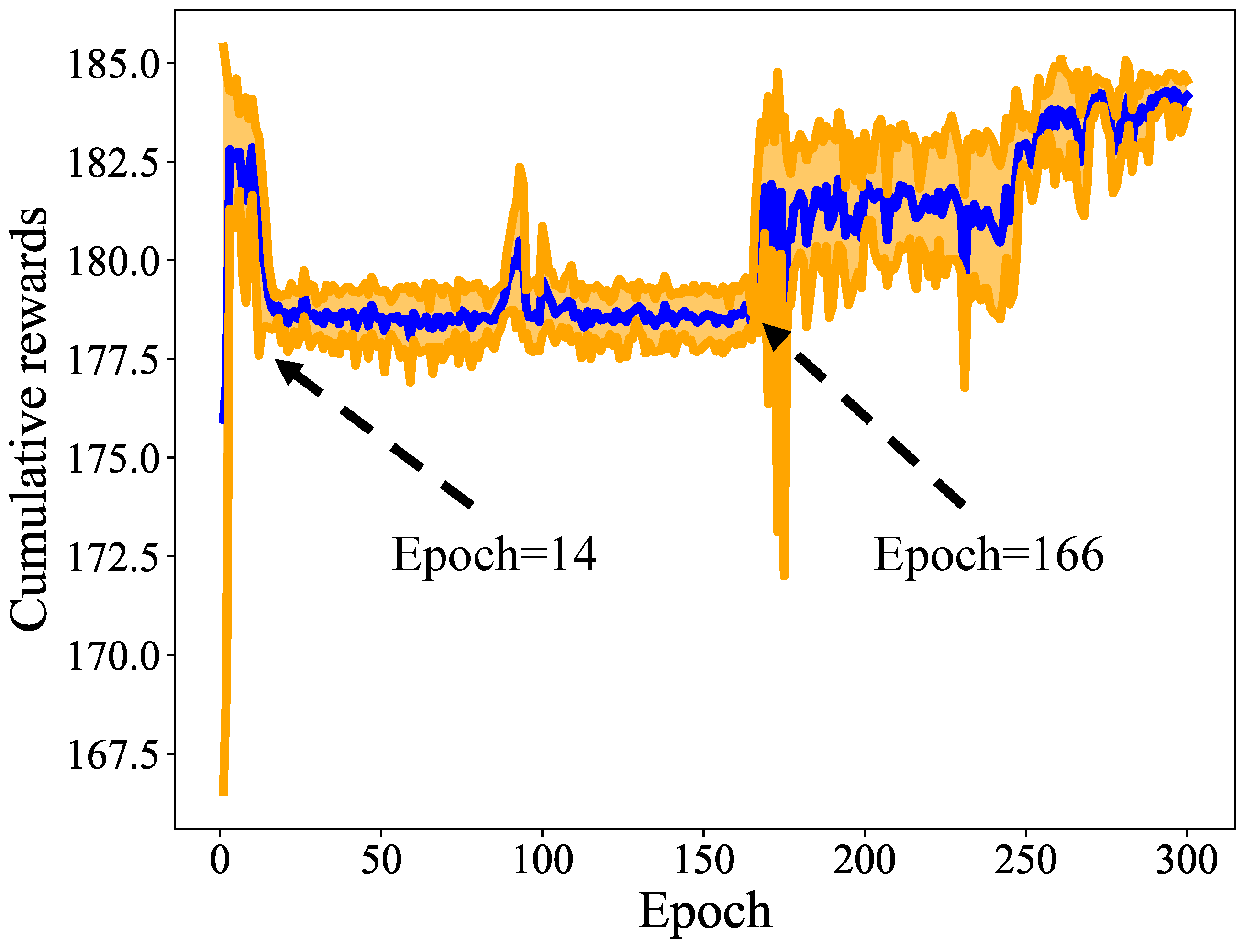
In this section, we verify whether the proposed reinforcement learning can always converge stably. For each epoch, the blue solid lines represent the average of five results, and the orange shadows represent the fluctuation. The upper bound of the shadow is the result of the mean plus standard deviation, and the lower bound is the result of the mean minus standard deviation. The results are shown in Figure 9.
From epoch 1 to epoch 14, the initialization of uniformly distributed parameters makes it easy for reinforcement learning to select actions with fewer edges. According to Equation (18), DQN can obtain higher rewards. However, a small number of edges easily make the network unconnected, and the penalty item in Equation (19) can reduce rewards. Therefore, at this stage, although higher rewards can be obtained, it is unstable. During epoch 14 to epoch 166, with the increase in training time, DQN explores the actions that make the network connected, but the reward value is small. This is because although the connectivity of the network is guaranteed, these actions generate a large number of edges. From Equation (18), it can be seen that a large number of edges can reduce rewards. Therefore, at this stage, although the reward is stable, it is relatively low. From epoch 166 to epoch 300, DQN gradually accumulates enough experience and explores actions to reduce the number of edges while ensuring connectivity. Finally, high-quality actions are obtained, and DQN converges stably to the solution with better connectivity and a small number of edges.

5.3. Verification of Connectivity

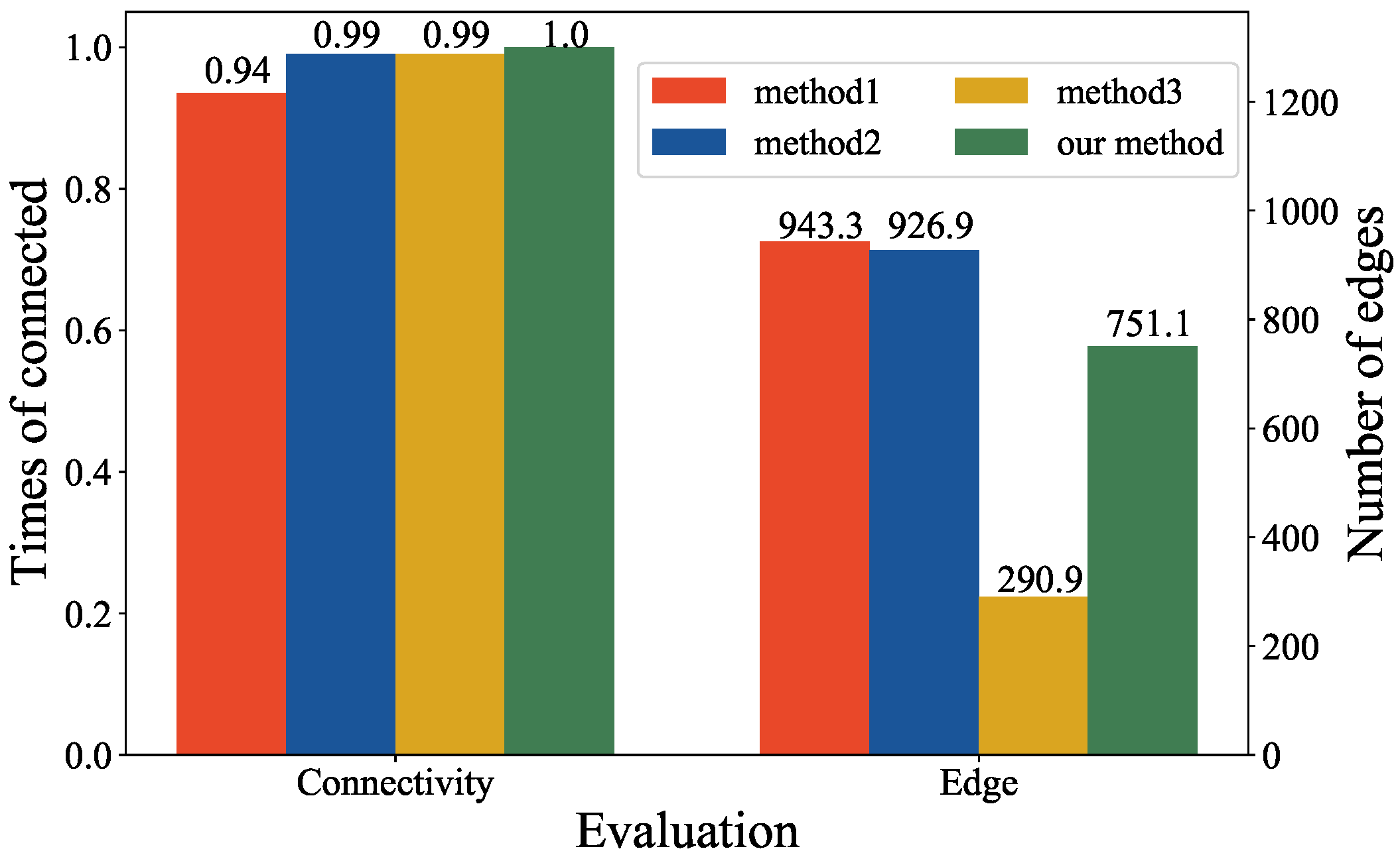
In this section, we verify the connectivity when the network is not attacked. The results are shown in Figure 10.
From Figure 10, it can be seen that the networks optimized using our method are connected throughout the entire simulation process. The connectivity of networks optimized using method 2 is stronger than that of method 1. From the experimental results, it can also be seen that compared to method 1 and method 2, the networks optimized using our method can reduce the number of edges by 20%. In addition, it can be seen that method 3 can effectively reduce the number of links and is much stronger than other methods. The reasons for the experimental results are as follows.
In terms of the number of links, since all neighbors are connected in method 1 and method 2, a large number of edges are generated. For the scale-free network, a large number of edges are concentrated on few nodes, and other nodes have very few edges. Therefore, for method 3, the number of links is very small. For the connectivity, in method 1, to avoid obstacles, the distance between UAVs increases. Due to the limited communication range of UAVs, the increased distance causes some links to be disconnected, and the network is divided into multiple sub-networks. Therefore, the network is no longer connected. In method 2, the cohesion can reduce the distance between UAVs and prevent links from being easily disconnected. Therefore, the network optimized using method 2 has better connectivity. In method 3, most nodes can establish reachable paths through critical nodes. Therefore, the connectivity can also be guaranteed. For our method, in the flight strategy, we use the improved cohesion to avoid an excessive concentration of UAVs and make the distribution of UAVs more uniform. Therefore, UAVs have more neighbors. Each UAV has the ability to establish a large number of links, which provides a foundation for connectivity. Based on the flight strategy, reinforcement learning is used to maintain connectivity and enable networks to have fewer edges. Therefore, compared to method 1 and method 2, our method has better performance.

5.4. Verification of Robustness

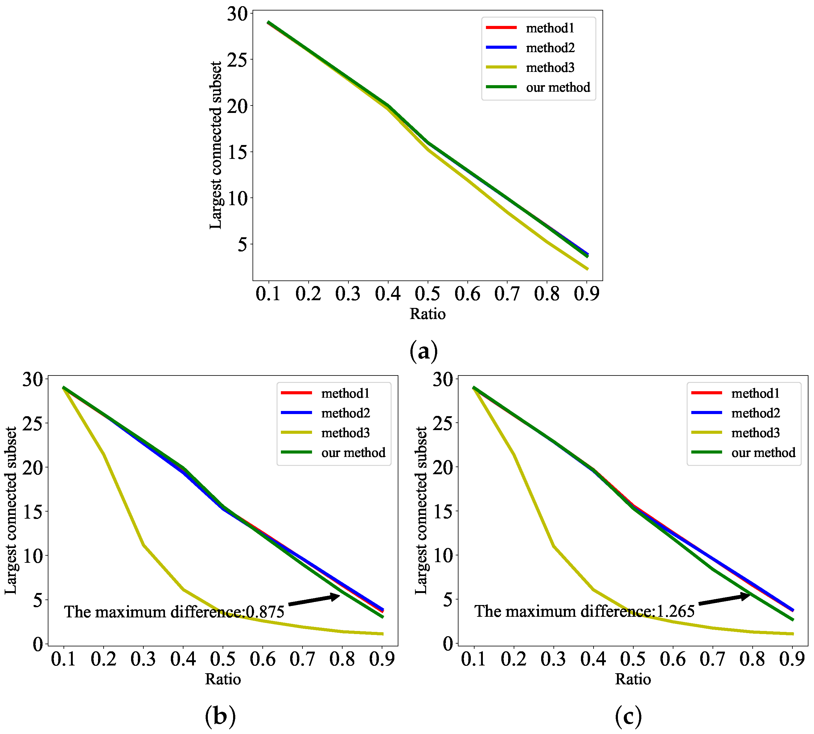
We use the same networks as in Section 5.3 to verify robustness. In the robustness experiments, the random failure, the failure based on the degree, and the failure based on betweenness are used to attack networks. The random failure means randomly removing nodes in network. For the failure based on the degree, nodes are sorted according to degree, and the nodes with a high degree are removed preferentially. In the failure based on betweenness, the importance of nodes is measured according to all paths in network. The nodes with high importance are removed preferentially. The ratio of failure is set from 10 % to 90 % . For example, a ratio equal to 10 % means that 10 % of nodes in the network are removed. The number of nodes in the largest connected subset is used to measure the robustness of the remaining network, and is recorded as L ( D ( G t ) ) . As L ( D ( G t ) ) increases, the robustness of the remaining network becomes stronger. The experimental results are shown in Figure 11.
In Figure 11a, the largest connected subset of our method is close to that of other methods. In Figure 11b,c, our method is only 0.875 and 1.265 lower than method 1 and method 2, respectively. Therefore, it can be concluded that the robustness of our method is close to that of method 1 and method 2 even though a large number of edges are reduced. In addition, it can be seen that the robustness of the networks optimized through method 1 and method 2 is very close. The robustness of method 3 is the worst. The reasons for the experimental results are as follows.
(i) Through the improved cohesion, our method can make the formation of UAVs compact. Moreover, the improved cohesion can avoid an excessive concentration of UAVs, and UAVs can have a large number of neighbors in other directions. Therefore, the formation provides networks with more selectable links, and the subsequent link selection algorithm can optimize more robust links. In the link selection, affected by reward and penalty, DQN selects as few links as possible and ensures robustness. Therefore, a large number of redundant links are is avoided. In addition, when encountering obstacles, each UAV can establish a large number of links with UAVs in multiple directions. Even if some UAVs fail, the connectivity of the networks can still be guaranteed. (ii) In the initial stage, compared to method 1, method 2 can make UAVs gather quickly, and the number of network links increases. When some UAVs fail, the links between UAVs are more preserved. Therefore, the robustness of the network optimized using method 2 is stronger than that of method 1. However, due to the influence of dense buildings, UAVs are not evenly distributed. In method 2, the cohesive force makes the formation of UAVs loose, and the number of links is reduced. When some UAVs fail, the number of links in the network further decreases and the robustness of the network sharply declines. Therefore, the robustness of the network optimized using method 2 is weaker than that of method 1. Based on the above discussion, it can be seen that method 2 is better than method 1 in the early stage, but is worse than method 1 in the case of dense obstacles. Therefore, their performance is close in the whole simulation process. For method 3, because a large number of links are concentrated on a few nodes, the scale-free network overly relies on some critical nodes. Once critical nodes fail, the robustness of the remaining network is difficult to guarantee. This result can be verified from Figure 11b,c. The methods based on degree and betweenness can effectively remove critical nodes. Therefore, in Figure 11b,c, the robustness of the network optimized using method 3 is the worst.
For different types of failure modes, it can be seen from Figure 11a–c that the random failure has the smallest impact on the network, followed by the failure based on the degree. The failure based on betweenness has the largest impact on the network. The reasons for the experimental results are as follows. Generally, the proportion of critical nodes in the network is small. Due to the random failure deleting nodes randomly, the critical nodes are difficult to delete, and the network still has high connectivity. The failure based on the degree can delete nodes with a larger degree, which makes a large number of edges decrease. Therefore, some reachable paths between nodes disappear, and the connectivity of the network is decreased. The failure based on betweenness can delete nodes according to reachable paths. Therefore, compared to the failure based on the degree, the failure based on betweenness can more directly destroy reachable paths, leading to a sharp decline in network connectivity.

5.5. Simulation in Unity 3D

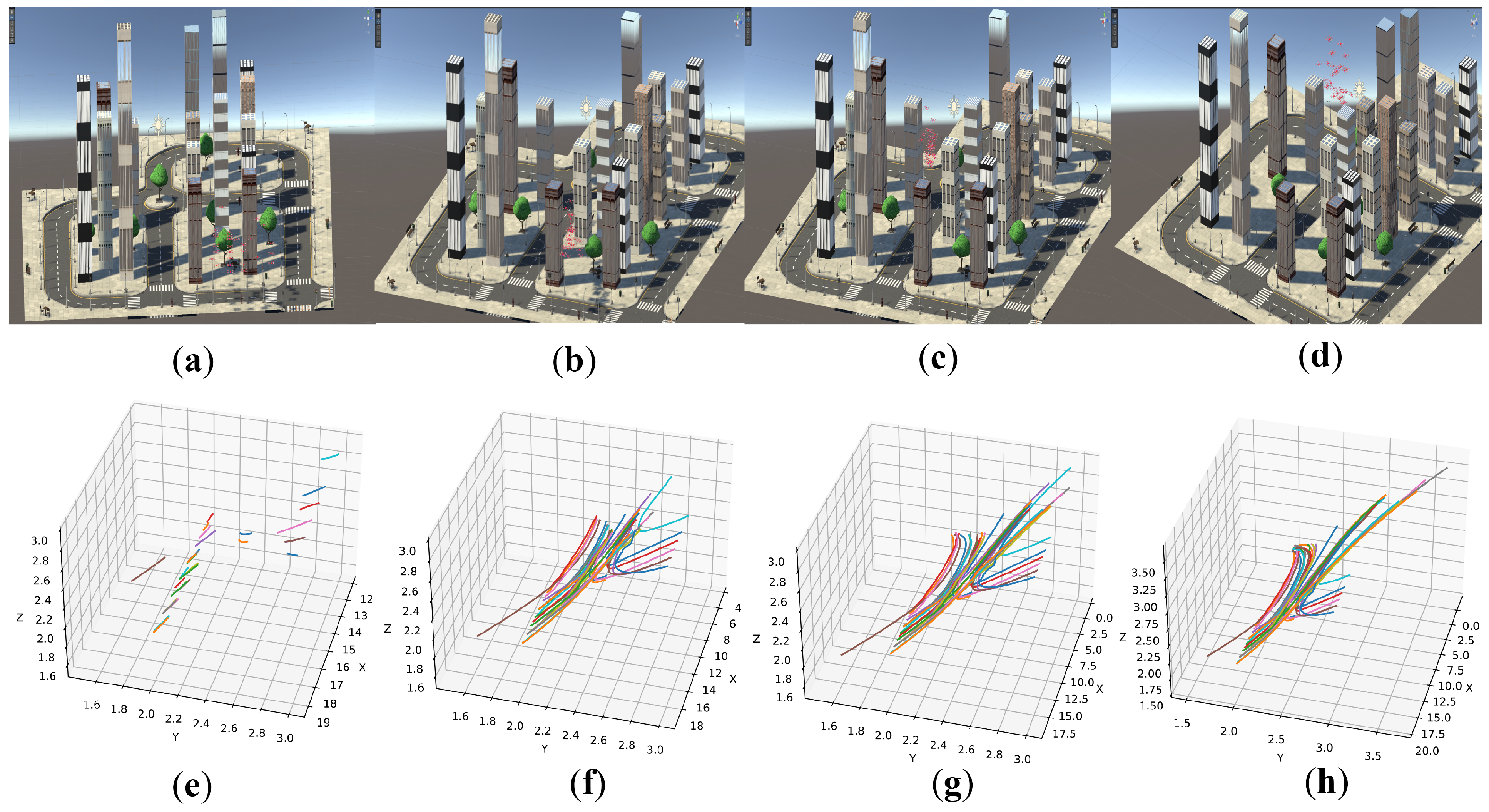
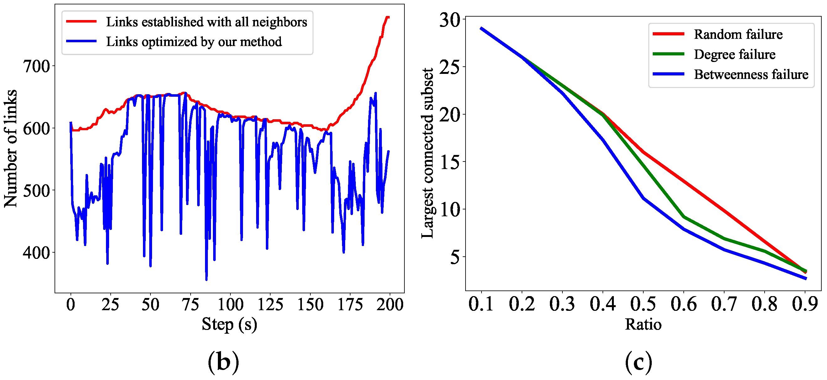
To further validate the effectiveness of our method, we use more realistic environments and physical models in Unity 3D. The experimental scenario and trajectories of UAVs are shown in Figure 12. The experiments of connectivity and robustness are shown in Figure 13.
From Figure 12a–d, it can be seen that in the urban scenario, UAVs can reach their destinations. Figure 12e–h shows that UAVs move to destinations in a curved manner. This is because buildings prevent UAVs from moving to the desired positions. In order to reach destinations, UAVs must detour around buildings, with curved trajectories. To verify the performance of our method in optimizing the number of links, the fully connected method is used as a comparison method. The fully connected method means that each UAV establishes links with all neighbors. As shown in Figure 13b, in the networks optimized using our method, the number of links is significantly lower than that of the fully connected method. To verify the robustness, we need to demonstrate that the networks optimized using our method are connected before being attacked. The results given in Figure 13a show that the proposed method can ensure the connectivity of the networks throughout the entire simulation process. When the networks are attacked, it can be seen from Figure 13c that under three attack modes, the largest connected subset of the remaining networks is similar to the results in Figure 11. In addition, from the robustness experiment, it can also be seen that the degree failure mode is much stronger than the random failure mode. The betweenness failure mode is significantly stronger than the other two failure modes.

6. Conclusions and Future Work

In this paper, a robust method for the multi-UAV network in a dense obstacle environment is proposed. The improved artificial potential field avoids the excessive movement of UAVs in directions with more neighbors. Therefore, the reduction in neighbors in other directions is avoided. Based on the positions of UAVs optimized using artificial potential fields, DQN is used to improve the robustness of the network and select fewer edges for each UAV. We verify the robustness of the network in three failure modes. The experimental results show that the network optimized using our method has high robustness and fewer links. In addition, we use Unity 3D to construct a more realistic urban scene and conduct experiments. The experimental results show that our method can still improve the robustness of the network.
In the future, we plan to consider more requirements of communication and more constraints of UAV. Because the coverage problem is an important topic, we will optimize the formation of UAVs by combining the coverage issues. In our method, UAVs cannot be stabilized at the optimal solution, resulting in meaningless movement. Therefore, we will further improve our method to address this issue. Furthermore, we will carry out experiments in the real environment to verify the effectiveness of our method.

Author Contributions

Conceptualization, W.Y. and Y.Z.; methodology, C.Z. (Chen Zhang); software, C.Z. (Chen Zhang) and H.W.; validation, C.Z. (Chen Zhang); formal analysis, C.Z. (Chuanfu Zhang); writing—review, C.Z. (Chen Zhang) and C.Z. (Chuanfu Zhang). All authors have read and agreed to the published version of the manuscript.

Funding

This work was supported by the National Natural Science Foundation of China (Grant Nos. 11725211 and 42201501).

Institutional Review Board Statement

Not applicable.

Informed Consent Statement

Not applicable.

Data Availability Statement

The data presented in this study have been shared to a public platform and can be found here: https://github.com/zc1993cn/multi-uavs, accessed on 1 August 2023.

Conflicts of Interest

The authors declare no conflict of interest.

References

  1. Wang, H.; Zhao, H.; Zhang, J.; Ma, D.; Li, J.; Wei, J. Survey on unmanned aerial vehicle networks: A cyber physical system perspective. IEEE Commun. Surv. Tutor. 2019, 22, 1027–1070. [Google Scholar] [CrossRef] [Green Version]
  2. Lakew, D.S.; Sa’ad, U.; Dao, N.N.; Na, W.; Cho, S. Routing in flying ad hoc networks: A comprehensive survey. IEEE Commun. Surv. Tutor. 2020, 22, 1071–1120. [Google Scholar] [CrossRef]
  3. Khalil, H.; Rahman, S.U.; Ullah, I.; Khan, I.; Alghadhban, A.J.; Al-Adhaileh, M.H.; Ali, G.; ElAffendi, M. A UAV-Swarm-Communication Model Using a Machine-Learning Approach for Search-and-Rescue Applications. Drones 2022, 6, 372. [Google Scholar] [CrossRef]
  4. Nawaz, H.; Ali, H.M.; Laghari, A.A. UAV communication networks issues: A review. Arch. Comput. Methods Eng. 2021, 28, 1349–1369. [Google Scholar] [CrossRef]
  5. Liu, J.; Zhou, M.; Wang, S.; Liu, P. A comparative study of network robustness measures. Front. Comput. Sci. 2017, 11, 568–584. [Google Scholar] [CrossRef]
  6. Lindqvist, B.; Haluska, J.; Kanellakis, C.; Nikolakopoulos, G. An Adaptive 3D Artificial Potential Field for Fail-safe UAV Navigation. In Proceedings of the 2022 30th Mediterranean Conference on Control and Automation (MED), Athens, Greece, 28 June–1 July 2022; pp. 362–367. [Google Scholar]
  7. Pan, Z.; Zhang, C.; Xia, Y.; Xiong, H.; Shao, X. An Improved Artificial Potential Field Method for Path Planning and Formation Control of the Multi-UAV Systems. IEEE Trans. Circuits Syst. II Express Briefs 2021, 69, 1129–1133. [Google Scholar] [CrossRef]
  8. Maza, I.; Ollero, A.; Casado, E.; Scarlatti, D. Classification of multi-UAV architectures. In Handbook of Unmanned Aerial Vehicles; Springer: Dordrecht, The Netherlands, 2015; pp. 953–975. [Google Scholar]
  9. Olfati-Saber, R. Flocking for multi-agent dynamic systems: Algorithms and theory. IEEE Trans. Autom. Control 2006, 51, 401–420. [Google Scholar] [CrossRef] [Green Version]
  10. Su, H.; Wang, X.; Lin, Z. Flocking of multi-agents with a virtual leader. IEEE Trans. Autom. Control 2009, 54, 293–307. [Google Scholar] [CrossRef]
  11. Consolini, L.; Morbidi, F.; Prattichizzo, D.; Tosques, M. Leader–follower formation control of nonholonomic mobile robots with input constraints. Automatica 2008, 44, 1343–1349. [Google Scholar] [CrossRef]
  12. Li, W.; Chen, Y.; Xiang, L. Cooperative Path Planning of UAV Formation Based on Improved Artificial Potential Field. In Proceedings of the 2022 IEEE 2nd International Conference on Electronic Technology, Communication and Information (ICETCI), Changchun, China, 27–29 May 2022; pp. 636–641. [Google Scholar]
  13. Xie, Y.; Wang, Y.; Wei, J.; Wang, J. Research on Radar Wave Avoidance for UAV Swarm Based on Improved Artificial Potential Field. In Proceedings of the 2022 10th International Conference on Intelligent Computing and Wireless Optical Communications (ICWOC), Chongqing, China, 10–12 June 2022; pp. 1–5. [Google Scholar]
  14. Koren, Y.; Borenstein, J. Potential field methods and their inherent limitations for mobile robot navigation. In Proceedings of the IEEE International Conference on Robotics and Automation (ICRA), Sacramento, CA, USA, 7–12 April 1991; Volume 2, pp. 1398–1404. [Google Scholar]
  15. Damas, B.D.; Lima, P.U.; Custodio, L.M. A modified potential fields method for robot navigation applied to dribbling in robotic soccer. In Proceedings of the RoboCup 2002: Robot Soccer World Cup VI 6; Springer: Berlin/Heidelberg, Germany, 2003; pp. 65–77. [Google Scholar]
  16. Howard, A.; Matarić, M.J.; Sukhatme, G.S. Mobile sensor network deployment using potential fields: A distributed, scalable solution to the area coverage problem. In Distributed Autonomous Robotic Systems 5; Springer: Berlin/Heidelberg, Germany, 2002; pp. 299–308. [Google Scholar]
  17. Li, F.; Wang, Y.; Tan, Y.; Ge, G. Mobile robots path planning based on evolutionary artificial potential fields approach. In Proceedings of the Conference of the 2nd International Conference on Computer Science and Electronics Engineering (ICCSEE 2013), Hangzhou, China, 22–23 March 2013; Atlantis Press: Amsterdam, The Netherlands, 2013; pp. 1314–1317. [Google Scholar]
  18. Pateria, S.; Subagdja, B.; Tan, A.H.; Quek, C. Hierarchical reinforcement learning: A comprehensive survey. ACM Comput. Surv. 2021, 54, 109. [Google Scholar] [CrossRef]
  19. He, Y.; Wang, Y.; Lin, Q.; Li, J. Meta-Hierarchical Reinforcement Learning (MHRL)-based Dynamic Resource Allocation for Dynamic Vehicular Networks. IEEE Trans. Veh. Technol. 2022, 71, 3495–3506. [Google Scholar] [CrossRef]
  20. Wang, X.; Li, W.; Song, W.; Dong, W. Connectivity Controlling of Multi-robot by Combining Artificial Potential Field with a Virtual Leader. In Proceedings of the 2013 IEEE International Conference on Systems, Man, and Cybernetics, Manchester, UK, 13–16 October 2013; pp. 374–377. [Google Scholar]
  21. Yi, S.; Luo, W.; Sycara, K. Distributed Topology Correction for Flexible Connectivity Maintenance in Multi-Robot Systems. In Proceedings of the 2021 IEEE International Conference on Robotics and Automation (ICRA), Xi’an, China, 30 May–5 June 2021; pp. 8874–8880. [Google Scholar]
  22. Capelli, B.; Fouad, H.; Beltrame, G.; Sabattini, L. Decentralized connectivity maintenance with time delays using control barrier functions. In Proceedings of the 2021 IEEE International Conference on Robotics and Automation (ICRA), Xi’an, China, 30 May–5 June 2021; pp. 1586–1592. [Google Scholar]
  23. Siligardi, L.; Panerati, J.; Kaufmann, M.; Minelli, M.; Ghedini, C.; Beltrame, G.; Sabattini, L. Robust area coverage with connectivity maintenance. In Proceedings of the 2019 International Conference on Robotics and Automation (ICRA), Montreal, QC, Canada, 20–24 May 2019; pp. 2202–2208. [Google Scholar]
  24. Dutta, A.; Ghosh, A.; Kreidl, O.P. Multi-robot informative path planning with continuous connectivity constraints. In Proceedings of the 2019 International Conference on Robotics and Automation (ICRA), Montreal, QC, Canada, 20–24 May 2019; pp. 3245–3251. [Google Scholar]
  25. Sun, C.; Hu, G.; Xie, L.; Egerstedt, M. Robust finite-time connectivity preserving consensus tracking and formation control for multi-agent systems. In Proceedings of the 2017 American Control Conference (ACC), Seattle, WA, USA, 24–26 May 2017; pp. 1990–1995. [Google Scholar]
  26. Gu, N.; Wang, D.; Peng, Z.; Liu, L. Observer-based finite-time control for distributed path maneuvering of underactuated unmanned surface vehicles with collision avoidance and connectivity preservation. IEEE Trans. Syst. Man Cybern. Syst. 2019, 51, 5105–5115. [Google Scholar] [CrossRef]
  27. Chen, B.; Ma, H.; Kang, H.; Liang, X. Multi-agent Distributed Formation Control Based on Improved Artificial Potential Field and Neural Network for Connectivity Preservation. In Proceedings of the 2021 IEEE International Conference on Unmanned Systems (ICUS), Beijing, China, 15–17 October 2021; pp. 455–460. [Google Scholar]
  28. Peng, Z.; Wang, D.; Li, T.; Han, M. Output-feedback cooperative formation maneuvering of autonomous surface vehicles with connectivity preservation and collision avoidance. IEEE Trans. Cybern. 2019, 50, 2527–2535. [Google Scholar] [CrossRef] [PubMed]
  29. Luo, W.; Yi, S.; Sycara, K. Behavior mixing with minimum global and subgroup connectivity maintenance for large-scale multi-robot systems. In Proceedings of the 2020 IEEE International Conference on Robotics and Automation (ICRA), Paris, France, 31 May–31 August 2020; pp. 9845–9851. [Google Scholar]
  30. Capelli, B.; Sabattini, L. Connectivity maintenance: Global and optimized approach through control barrier functions. In Proceedings of the 2020 IEEE International Conference on Robotics and Automation (ICRA), Paris, France, 31 May–31 August 2020; pp. 5590–5596. [Google Scholar]
  31. Panerati, J.; Gianoli, L.; Pinciroli, C.; Shabah, A.; Nicolescu, G.; Beltrame, G. From swarms to stars: Task coverage in robot swarms with connectivity constraints. In Proceedings of the 2018 IEEE International Conference on Robotics and Automation (ICRA), Brisbane, Australia, 21–25 May 2018; pp. 7674–7681. [Google Scholar]
  32. Wu, S.; Pu, Z.; Liu, Z.; Qiu, T.; Yi, J.; Zhang, T. Multi-target coverage with connectivity maintenance using knowledge-incorporated policy framework. In Proceedings of the 2021 IEEE International Conference on Robotics and Automation (ICRA), Xi’an, China, 30 May–5 June 2021; pp. 8772–8778. [Google Scholar]
  33. Lin, C.; Luo, W.; Sycara, K. Online Connectivity-aware Dynamic Deployment for Heterogeneous Multi-Robot Systems. In Proceedings of the 2021 IEEE International Conference on Robotics and Automation (ICRA), Xi’an, China, 30 May–5 June 2021; pp. 8941–8947. [Google Scholar]
  34. Feng, J.; Dixon, W.E.; Shea, J.M. Positioning helper nodes to improve robustness of wireless mesh networks to jamming attacks. In Proceedings of the 2017 IEEE Global Communications Conference (GLOBECOM 2017), Singapore, 4–8 December 2017; pp. 1–6. [Google Scholar]
  35. Hazra, K.; Shah, V.K.; Roy, S.; Deep, S.; Saha, S.; Nandi, S. Exploring Biological Robustness for Reliable Multi-UAV Networks. IEEE Trans. Netw. Serv. Manag. 2021, 18, 2776–2788. [Google Scholar] [CrossRef]
  36. Selvam, P.K.; Raja, G.; Rajagopal, V.; Dev, K.; Knorr, S. Collision-free Path Planning for UAVs using Efficient Artificial Potential Field Algorithm. In Proceedings of the 2021 IEEE 93rd Vehicular Technology Conference (VTC2021-Spring), Virtual, 25–28 April 2021; pp. 1–5. [Google Scholar]
  37. Wang, Y.; Sun, X. Formation control of multi-UAV with collision avoidance using artificial potential field. In Proceedings of the 2019 11th International Conference on Intelligent Human–Machine Systems and Cybernetics (IHMSC), Hangzhou, China, 24–25 August 2019; Volume 1, pp. 296–300. [Google Scholar]
  38. Liang, Q.; Zhou, H.; Xiong, W.; Zhou, L. Improved artificial potential field method for UAV path planning. In Proceedings of the 2022 14th International Conference on Measuring Technology and Mechatronics Automation (ICMTMA), Changsha, China, 15–16 January 2022; pp. 657–660. [Google Scholar]
  39. Yan, S.; Pan, F.; Xu, J.; Song, L. Research on UAV Path Planning Based on Improved Artificial Potential Field Method. In Proceedings of the 2022 2nd International Conference on Computer, Control and Robotics (ICCCR), Shanghai, China, 18–20 March 2022; pp. 1–5. [Google Scholar]
  40. Xie, H.; Qu, Y.; Fan, G.; Zhu, X. Three-Dimensional Path Planning of UAV Based on Improved Artificial Potential Field. In Proceedings of the 2021 40th Chinese Control Conference (CCC), Shanghai, China, 26–28 July 2021; pp. 7862–7867. [Google Scholar]
  41. Fernando, M. Online flocking control of UAVs with mean-field approximation. In Proceedings of the 2021 IEEE International Conference on Robotics and Automation (ICRA), Xi’an, China, 30 May–5 June 2021; pp. 8977–8983. [Google Scholar]
  42. Luong, N.C.; Hoang, D.T.; Gong, S.; Niyato, D.; Wang, P.; Liang, Y.C.; Kim, D.I. Applications of deep reinforcement learning in communications and networking: A survey. IEEE Commun. Surv. Tutor. 2019, 21, 3133–3174. [Google Scholar] [CrossRef] [Green Version]
  43. Malli, I.; Bechlioulis, C.P.; Kyriakopoulos, K.J. Robust Distributed Estimation of the Algebraic Connectivity for Networked Multi-robot Systems. In Proceedings of the 2021 IEEE International Conference on Robotics and Automation (ICRA), Xi’an, China, 30 May–5 June 2021; pp. 9155–9160. [Google Scholar]
  44. Bulut, E.; Szymanski, B.K. Constructing limited scale-free topologies over peer-to-peer networks. IEEE Trans. Parallel Distrib. Syst. 2013, 25, 919–928. [Google Scholar] [CrossRef] [Green Version]
Figure 1. Task of obstacle avoidance for a multi-UAV network.
Drones 07 00506 g001
Figure 2. Framework of our method.
Drones 07 00506 g002
Figure 3. Influence of obstacles on positions of UAVs. The green UAVs cannot establish links with blue UAVs. The orange UAV can establish links with green UAVs and blue UAVs. (a) Positions of UAVs before encountering obstacles. (b) Positions of UAVs when encountering obstacles. (c) Positions of UAVs after encountering obstacles.
Drones 07 00506 g003
Figure 4. Computational process from state to action. The dotted squares represent the vectors related to UAV2 in the computational process. (a) Computational process from state to action in a centralized distributed manner. (b) Computational process from state to action in a distributed manner.
Drones 07 00506 g004
Figure 5. Multi-UAV network with random actions.
Drones 07 00506 g005
Figure 6. Flight process of UAVs in an urban environment. In (ac), the green points represent UAVs. In (df), the lines of different colors represent the flight trajectories of different UAVs. (a) Positions of the UAVs at time 0. (b) Positions of the UAVs at time 20. (c) Positions of the UAVs at time 200. (d) Trajectories of UAVs from 0 to 2. (e) Trajectories of UAVs from 0 to 20. (f) Trajectories of UAVs from 0 to 200.
Drones 07 00506 g006
Figure 7. Number of UAV neighbors.
Drones 07 00506 g007
Figure 8. Shortest distance between UAVs.
Drones 07 00506 g008
Figure 9. Convergence of reinforcement learning. The orange shadows represent the fluctuation in rewards.
Drones 07 00506 g009
Figure 10. Connectivity and the number of edges.
Drones 07 00506 g010
Figure 11. Comparative experiments of three methods under different failure modes. (a) Random failure. (b) Failure based on degree. (c) Failure based on betweenness.
Drones 07 00506 g011
Figure 12. Flight process of UAVs in Unity 3D. In (ad), the red objects represent UAVs. In (eh), the lines of different colors represent the flight trajectories of different UAVs. (a) Positions of UAVs at time 0. (b) Positions of UAVs at time 100. (c) Positions of UAVs at time 150. (d) Positions of UAVs at time 200. (e) Trajectories of UAVs from 0 to 10. (f) Trajectories of UAVs from 0 to 100. (g) Trajectories of UAVs from 0 to 150. (h) Trajectories of UAVs from 0 to 200.
Drones 07 00506 g012
Figure 13. Connectivity and robustness of the network optimized using our method in Unity 3D. (a) Connectivity of multi-UAV network. (b) Number of edges in network. (c) Robustness under three failure modes.
Drones 07 00506 g013aDrones 07 00506 g013b
Table 1. Parameters of our method.
ParametersValue
Maximum velocity of UAVs v m a x = 2.5 m/s
Safe distance of UAVs s r = 0.1  m
Communication range of UAVs r = 10  m
Coefficient of attraction α = 10
Coefficient of repulsion β = 1000
Coefficient of cohesion η = 0.003 , θ = 0.001
Coefficient of l l = 0.001
Batch size of DQN b s = 64
Learning rate of DQN l r = 0.01
ϵ -greedy of DQN ϵ = 0.8
Discount factor of DQN γ = 0.9
Replay buffer of DQN r b = 256
Target update frequency of DQN t r = 80
Disclaimer/Publisher’s Note: The statements, opinions and data contained in all publications are solely those of the individual author(s) and contributor(s) and not of MDPI and/or the editor(s). MDPI and/or the editor(s) disclaim responsibility for any injury to people or property resulting from any ideas, methods, instructions or products referred to in the content.