Article

Design of Non-Conventional Flight Control Systems for Bioinspired Micro Air Vehicles

by
Estela Barroso-Barderas
1,2,
Ángel Antonio Rodríguez-Sevillano
2,*,
Rafael Bardera-Mora
1,
Javier Crespo-Moreno
2 and
Juan Carlos Matías-García
1
1
Instituto Nacional de Técnica Aeroespacial (INTA), 28850 Torrejón de Ardoz, Spain
2
Escuela Técnica Superior de Ingeniería Aeronáutica y del Espacio, Universidad Politécnica de Madrid, 28040 Madrid, Spain
*
Author to whom correspondence should be addressed.
Drones 2022, 6(9), 248; https://doi.org/10.3390/drones6090248
Submission received: 30 July 2022 / Revised: 24 August 2022 / Accepted: 5 September 2022 / Published: 9 September 2022
(This article belongs to the Section Drone Design and Development)

Abstract

:
This research focuses on the development of two bioinspired micro air vehicle (MAV) prototypes, based on morphing wings and wing grid wingtip devices. The morphing wings MAV tries to adapt the aerodynamics of the vehicle to each phase of flight by modifying the vehicle geometry, while the wing grid MAV aims to minimize the aerodynamic and weight penalty of these vehicles. This work focuses on the design methodology of the flight control system of these MAVs. A preliminary theoretical conceptual design was used to verify the requirements, wind tunnel tests were performed to determine aerodynamic characteristics, and suitable materials were selected. The hardware and software configuration designed for the control system, which fulfills the objective of adaptive and optimal control in the wingtip-based prototype of the wing grid, is described. Finally, the results of the flight control on the prototype MAVs are analyzed.

1. Introduction

The design of the prototypes is part of the innovation projects developed by the authors, aimed at the research and development of aerospace platforms with unconventional geometries and technologies. A good interpretation of the term morphing can be understood as the modification of the shape or structure of a body, or, in other words, deformation of its geometry, complying with previously defined requirements, referring to both small and large aircraft scales. In this sense, it is necessary to review the types of variable-geometry wings that have been investigated so far. Variable geometry wing classification can be divided into three categories [1]: modification of the wing planform, transformation of the wing out of its original plane, and adjustment of the airfoil. Within the first group, a modification of the wing planform would be a change in wing chord, wingspan, or sweep angle. The category of transformation of the wing out of its original plane would include changing the dihedral angle, the twist, and the sweep angle. Finally, the airfoil adjustment would include the change of wing thickness and wing curvature. Many variable geometry wing approaches are intended for two-dimensional configurations. Geometric modifications in a two-dimensional plane tend to be easier to manufacture and assemble, because only a part of the wing would be subject to design modifications [2]. To achieve any of the above modifications, the application of suitable materials with certain specifications that meet the requirements of an optimal wing modification is required. Thus, the materials under investigation are called smart materials. These materials possess one or more properties that can be significantly modified in a controlled manner by an external stimulus, such as temperature or mechanical stress, in a reversible manner. Smart materials can be divided into piezoelectric actuators (PZT), shape memory polymers (SMP), and shape memory alloy actuators (SMA) [1]. Wing-curvature modification is the most investigated approach in new UAV designs, based on the morphing concept. The methods applied to realize wing-curvature modifications are: SMA, internal mechanisms, and PZT.
Two approaches to wing morphing can be identified: wing morphing for flight mission and wing morphing for vehicle control. In the scope of this research, the morphing concept is applied to control the shape change of any aerodynamic surface of the aircraft. It always complies with the flight envelope, and, moreover, it is only applied in micro air vehicles, MAVs [3].
In this context, morphing refers to changes in the curvature of the aircraft wings, and the marginal edge assembly of the wing grid corresponds to the installation of special devices at the tip of the wing to reduce induced drag. Both are based on the use of new materials suitable to change the dimensions of the main wings of any aircraft and improve flight qualities [4].
In the case of morphing wings, the modifications are related to changes in the external geometry of the wing (both inboard and outboard) through electromechanical actuation. The aim of this technique is to control the camber, without the usual penalty due to the necessary mechanical elements. Modification of the camber is directly related to aerodynamic characteristics (CL, CD) in the phases of flight.
The second device is a wingtip device called a wing grid [5]. This device consists of a set of wingtips located at the tips of the wings spaced a certain distance apart, simulating the primary feathers of birds [6]. These flaps are deployed according to the controller’s need, causing an increase in wingspan (b), which in turn implies an increase in the aspect ratio of the wings (AR = b 2 S ). One of the problems that limits the aerodynamic efficiency (CL/CD) of the aircraft is the increased drag inherent in certain configurations. Aircraft wings generate vortices resulting in increased aircraft drag; the planform of the wing determines the intensity of the vortices and is the source of the induced drag. In this sense, it is interesting to explore new concepts to improve the airfoil or some aerodynamic characteristics ( C L m á x ,   C D m í n ,   ( C L C D   ) m á x )   in certain phases (take-off, landing, loiter). Cost can be reduced by decreasing weight or by increasing flight time or distance [5]. The wing grid device consists mainly of polymer composite surfaces to reduce the induced drag on the wings. The performance of the wing grid in relation to installation, shape, and control needs to be investigated.
The on-board system that controls the flight of any aircraft is the flight control computer. This computer is responsible for controlling the movement of the aircraft’s aerodynamic and control surfaces, according to pre-set laws. Additionally, and depending on the size of the aircraft, this computer may be responsible for flight management.
As new functions appear in the context of flight control, they must be handed over to any onboard computer to be successfully executed. This case focuses on giving control of the vehicles based on these two concepts, morphing and wing grid, to the flight control computer. The motion control of surfaces is based on control laws calculated on the flight control computer. The complexity of the calculation of a control law will depend on the control surfaces installed on board, their actuators, the operating conditions, and the required accuracy.
The aim of this work is to analyze the possibilities of exploring and applying flight control laws according to flight profile criteria, when vehicle aerodynamics enter the control loop [7]. Moreover, to develop similar adaptive control technique for both prototypes, although the concept of wing geometry variation is different: a morphing configuration with piezoelectric actuators and a wing grid configuration with the wing-tip surfaces deployed by means of electrical motors.
Low-cost electronic components have been used to obtain the control. Using the microcontroller on an Arduino board and a series of actuators (stepper motors and servomotors), the extension and retraction of the wing grid is achieved. Finally, a radio control unit is connected to the Arduino board to remotely control the prototype.
In both cases, the authors designed testbeds to carry out and to demonstrate some control strategies and the hardware necessary for both prototypes. Each prototype shows capabilities of vehicle control: the morphing-controlled MAV (MM) focuses on longitudinal control, while the wing grid MAV prototype (WGM) focuses on lateral control.

2. Theoretical Background

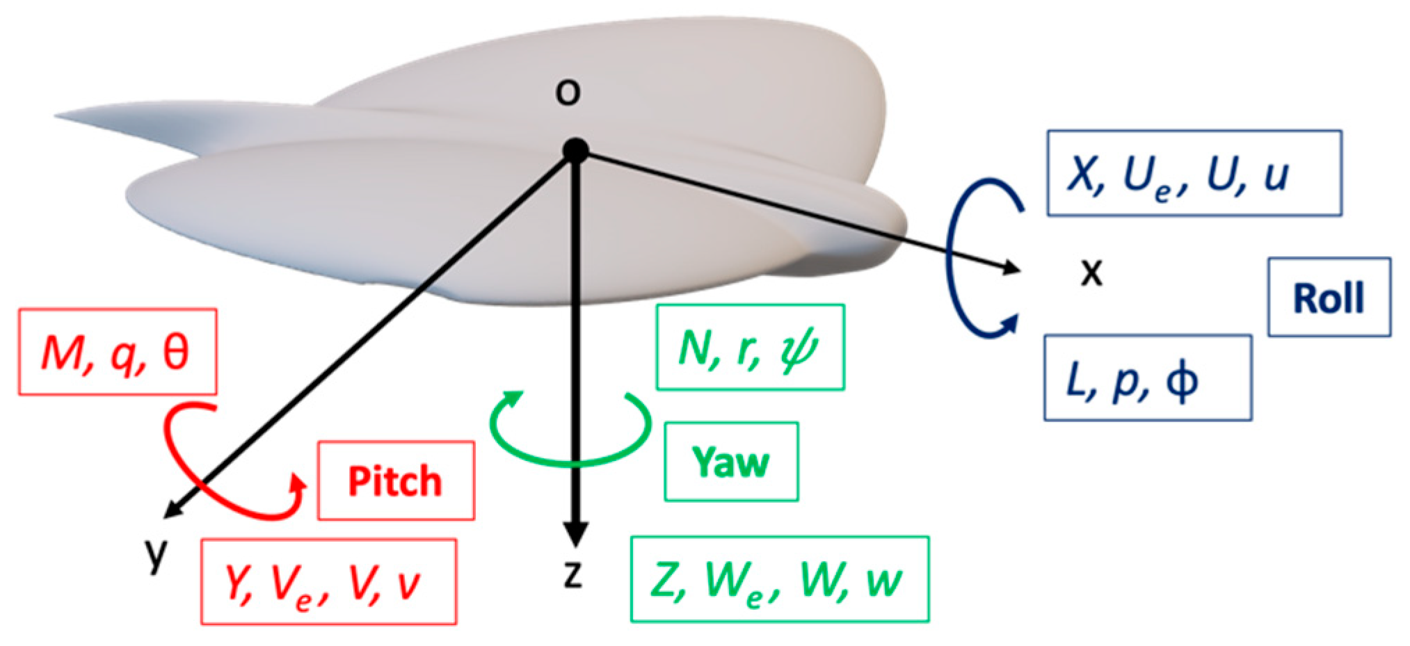
2.1. Stability and Control Properties of the Vehicles

Once an exhaustive study of the behavior of the material [8] and the aerodynamics of the vehicles was performed, it is necessary to study their stability. In accordance with this, there should be a properly designed control system; otherwise, a redesign of the geometry will have to be done. The main objective will obviously be to obtain a controllable drone that can fly autonomously; the next step will be the development of the control system that allows MAVs to carry out the missions for which they have been conceived.
Given that the design of both drones is far from the typical configurations in conventional aircraft, a detailed study must be carried out, reviewing the simplifications made in the usual bibliography on flight mechanics and aircraft control [9,10], to guarantee that the approaches followed and the results obtained are adjusted to the peculiarities of the vehicle under study.
Thus, some of the main aspects to consider are as follows.
  • In both cases, the flight regime must be considered, since the low values of characteristic length (c) and speed lead to a Reynolds number ( Re = ρ U c / ν ) much lower than that of conventional flight regimes. Drones develop Re values close to 105 under their typical flight conditions (U < 20 m/s) [11], compared to a value of Re = 1.1 × 10⁸ for a typical commercial aircraft.
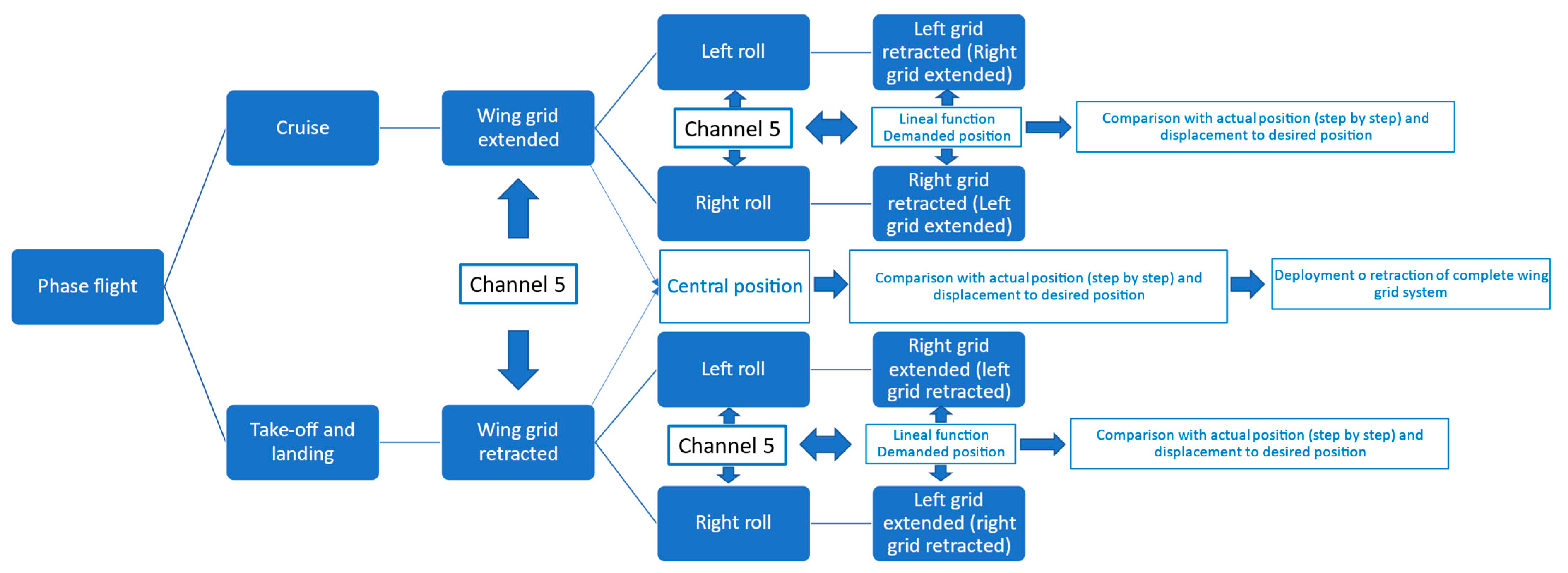
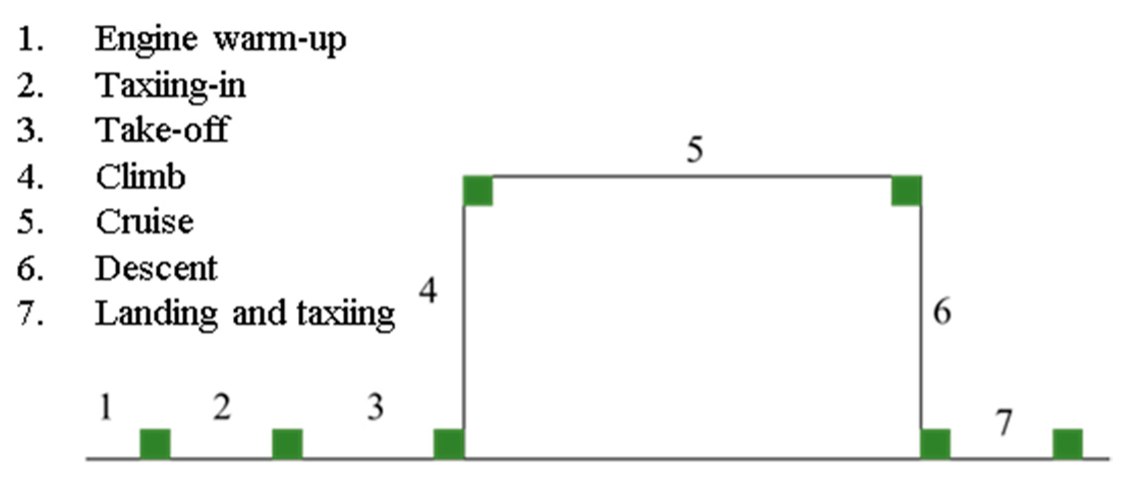
  • In both cases, the possibility of modifying the wing planform may serve as a flight attitude control of the MAV. The flight can be considered in several phases (Figure 1), depending on the flight profile. Thus, optimal control will introduce different control strategies depending on the flight phase flown. In this case, the flight problem becomes a continuous reconfiguration of the flight taking the law of detection, actuation, and control of the flight, by means of the variables already explained above.
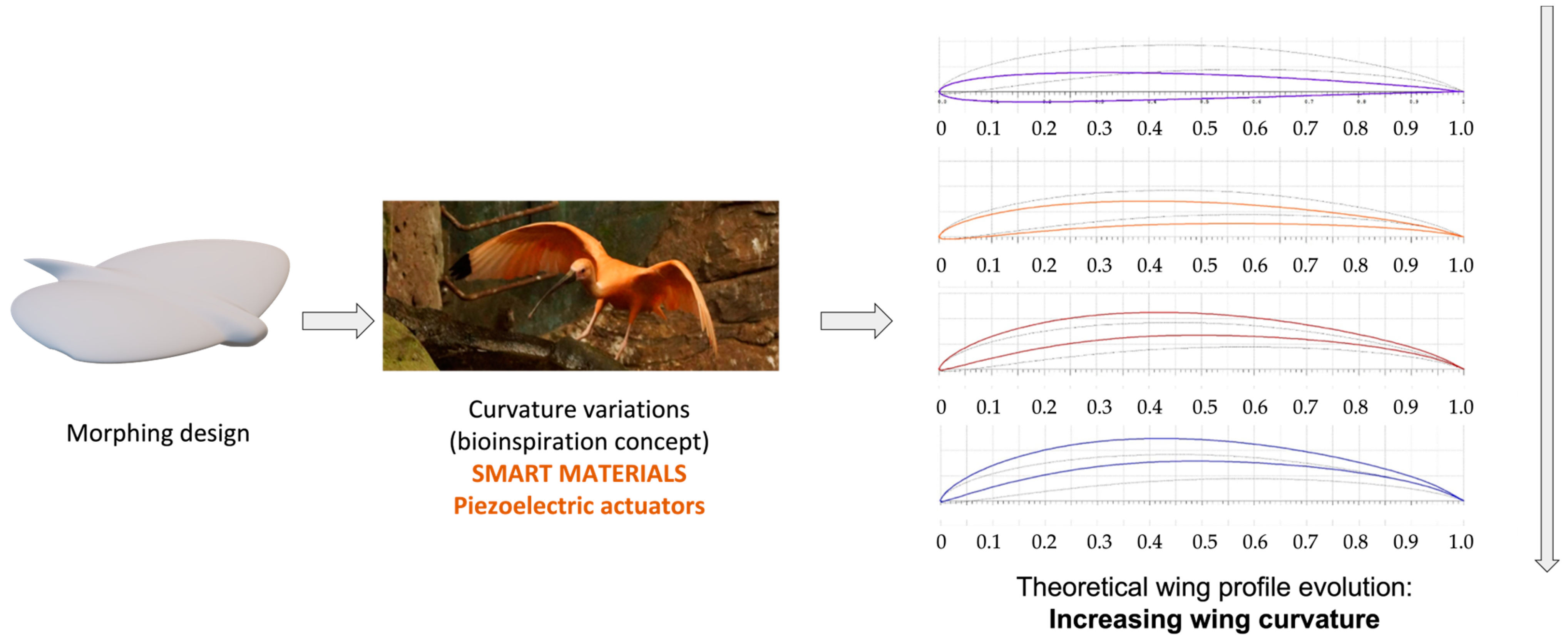
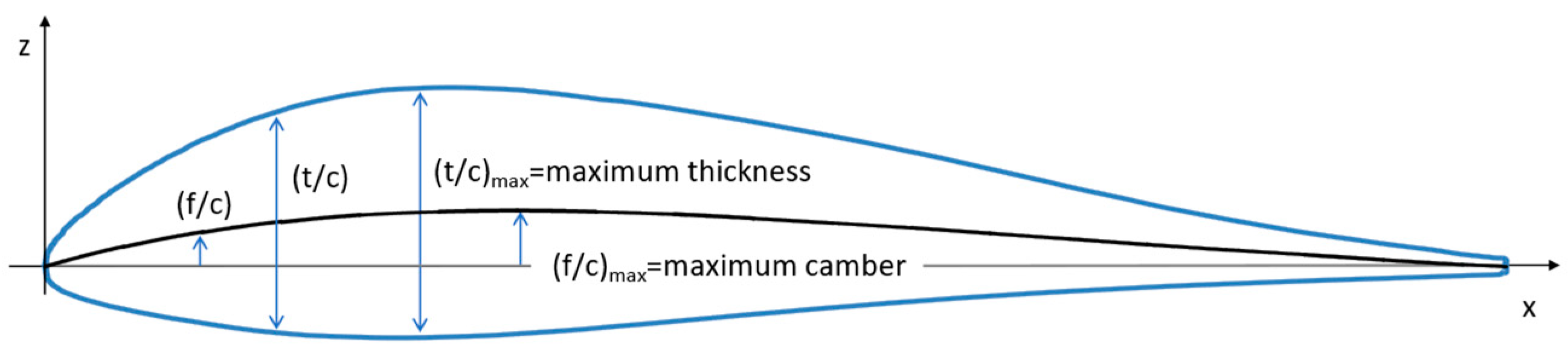
  • In the morphing prototype (MM), the absence of conventional control surfaces must be considered. In this case, these surfaces have been substituted by modification of the wing curvature. This modification leads to a change in the lift coefficient (CL), drag coefficient (CD), and pitch moment coefficient (Cm) from the cruise configuration to maneuver. According to this, it is necessary to know the substitution of the usual control parameters by the relationship between the applied voltage (V) and the curvature (y/c), analyzing the capability of the corresponding geometry change to achieve adequate control of the vehicle.
  • For the morphing prototype (MM), it is interesting to state the absence of horizontal and vertical stabilizers, which greatly affects the stability of the vehicle.
  • For the wing grid prototype (WGM), in addition to the reduction in induced drag (CDi), and the increase in lift due (CL) to extension of the wing grid device, this paper focuses on the use of this wing grid to modify the lateral stability or control of the MAV with the asymmetrical deployment of the device.
The study of the stability and control of these air vehicles is undertaken by modeling them as systems expressed by means of their equations of motion [9,10]. The nomenclature is presented in Figure 2.
The basis of these equations is Newton’s second law, which, generalized for a non-deformable body, considers the conservation laws of momentum and angular momentum, expressed for an inertial reference frame as:
F = d d t ( m V )  
G = d d t ( I = ω )  
The expansion of these two vectorial equations leads to a six-scalar equation system, well-known as Euler’s equations of aircraft motion:
m ( U ˙ r V + q W ) = X a + X g + X c + X p + X d m ( V ˙ p W + r U ) = Y a + Y g + Y c + Y p + Y d m ( W ˙ q U + p V ) = Z a + Z g + Z c + Z p + Z d I x p ˙ ( I y I z ) q r I x z ( p q + r ˙ ) = L a + L g + L c + L p + L d I y q ˙ + ( I x I z ) p r + I x z ( p 2 r 2 ) = M a + M g + M c + M p + M d I z r ˙ ( I x I y ) p q + I x z ( q r p ˙ ) = N a + N g + N c + N p + N d
These six equations of motion require that the forces and moments (the terms on the right side of the equations) should be adequately described. These forces and moments are due to the following effects: aerodynamic (a), gravitational (g), aircraft control (c), propulsive (p), and atmospheric disturbances (d).
In a simplified form, without atmospheric disturbances (and adequate for most geometries), it can be resumed as follows:
m ( u ˙ + q W ) = X a + X g + X c + X p m ( v ˙ p W + r U ) = Y a + Y g + Y c + Y p m ( w ˙ q U ) = Z a + Z g + Z c + Z p I x p ˙ I x z r ˙ = L a + L g + L c + L p I y q ˙ = M a + M g + M c + M p I z r ˙ I x z p ˙ = N a + N g + N c + N p  
If flight conditions are restricted to symmetric, stationary, levelled, trimmed, and non-accelerated flight, and, moreover, the equations are presented in their non-dimensional forms, the simplification are substantial:
0 = 1 2 ρ U 2 S c ¯   C D + T 0 = 1 2 ρ U 2 S c ¯   C L + m g I x p ˙ = 1 2 ρ U 2 S b   [ C l w i n g   g r i d   d e p l o y m e n t + C l δ r u d d e r v a t o r δ r u d d e r v a t o r ] I y q ˙ = 1 2 ρ U 2 S c ¯   ( C m α   α + C m δ p i t c h δ p i t c h )
Not all these variables are determined throughout the paper. The main variables texted or calculated are the following, with their conventional notation:
C L = L 1 2 ρ U 2 S     C D = D 1 2 ρ U 2 S C m = M 1 2 ρ U 2 S c ¯ C m α = C m α C L α = C L α C l δ = C l δ  

2.2. Morphing MAV (MM) Concept

The study of morphing configuration achieved to date has addressed aspects of control of wing-planform change and curvature. In this context, various control functionalities can be found in mission performance values, such as range (and endurance) and speed, under specific flight conditions related to wind speed, altitude, angle of attack, and angle of roll [9].
A particular case, the concept of morphing, is based on the change in flight of the curvature of the airfoil that forms the wing [11], as shown in Figure 3.
On the one hand, the increase in the lift coefficient ( C L )   due to the increase in the curvature ( f / c   )   of the wing would allow the aircraft to fly at lower speeds. Therefore, it would be possible to obtain better conditions in a real-time video recording; or, in the take-off and landing phases, to take off at lower speeds, or to pick up the drone at a lower speed upon landing. However, on the other hand, reducing the curvature values would provide a higher ratio ( C L / C D ) ;   potentially, improving the range (R), endurance (E), and power consumed during cruise. Figure 4 shows the MAV model with adaptive wing geometry (morphing).

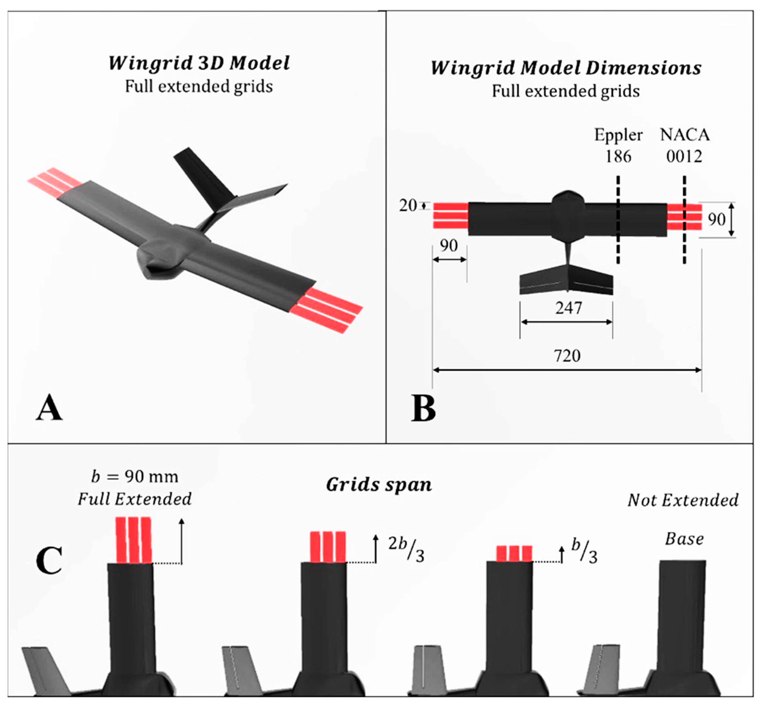
2.3. Wing Grid (WGM) Concept

If weight represents one of the main penalties for aircraft flight, reducing drag will be the main objective of aerodynamic research. Weight (lift) and drag are the binomials that must be worked on conceptually. Over the years, several investigations have been carried out in order to achieve a reduction in induced drag ( D i   ,   C D i )   without increasing wingspan (b) [12]. The observation of nature, in the case of flight, allows the adoption of interesting proposals. In this regard, biologists have studied birds such as eagles, hawks, condors, and vultures and discovered that they all have primary feathers with slots that allow for reduced drag during glide flight [6]. A promising design based on the observation of these primary feathers of birds was the wing grid system, developed through research by the La Roche brothers in 1993 [4]. This design consisted of a set of winglets at the tip of the wing separated by a certain distance, giving rise to a series of slots between them. In the design proposed in this work, the devices can be deployed by the control system depending on flight needs. Therefore, the wingspan will increase when the wing grid system is deployed; the increase in wingspan (b) directly influences a reduction in the induced drag coefficient ( C D i ) . The wing grid wingtip device causes an increase in the core radius of the vortices, in addition to a larger separation between the vortices. In other words, the rectangular wing with the wing grid system has a lower induced drag than the same wing without them, at the same span.
In addition to the above, [5] conducted wind tunnel tests showing that the primary feathers of birds reduced the induced drag ( C D i ) , and Bennett [5] concluded that the wing grid device only showed its benefits above a critical Reynolds number ( R e c )   and, while at high speeds, the effect reducing induced drag only occurred at low angles of attack (α).
The number of aircraft with such wingtip devices is scarce. In addition to wind tunnel studies on the effects of these devices on vehicle aerodynamics, prototypes and flight tests were carried out.
The current design of the MAV fitted with the wing grid assembly (Figure 5) aims not only to reduce the induced drag ( C D i ) but also to control the aircraft by antisymmetric extension and retraction of the wing grid device. Such deployment is combined with the deflection of the rudders of a V-tail, to allow the aircraft to turn.
The design of the MAV is based on a rectangular wing with three grids at the tip of the wing, with a gap of 4.5 mm between each of them (see Figure 6). The rectangular wing is composed of Eppler 186 airfoils, while the grids are composed of NACA 0012 airfoils. The three elements of the wing grid have the same values for taper ratio, sweep angle, and angle of incidence as the rectangular wing. The chord of the wing is 90 mm along the wingspan, while the chord of the grids is 20 mm. The wingspan of the MAV with the grids retracted is 540 mm and, when the grids are extended, this dimension reaches 720 mm.

3. Aerodynamic Data of Both MAVs (MM, WGM)

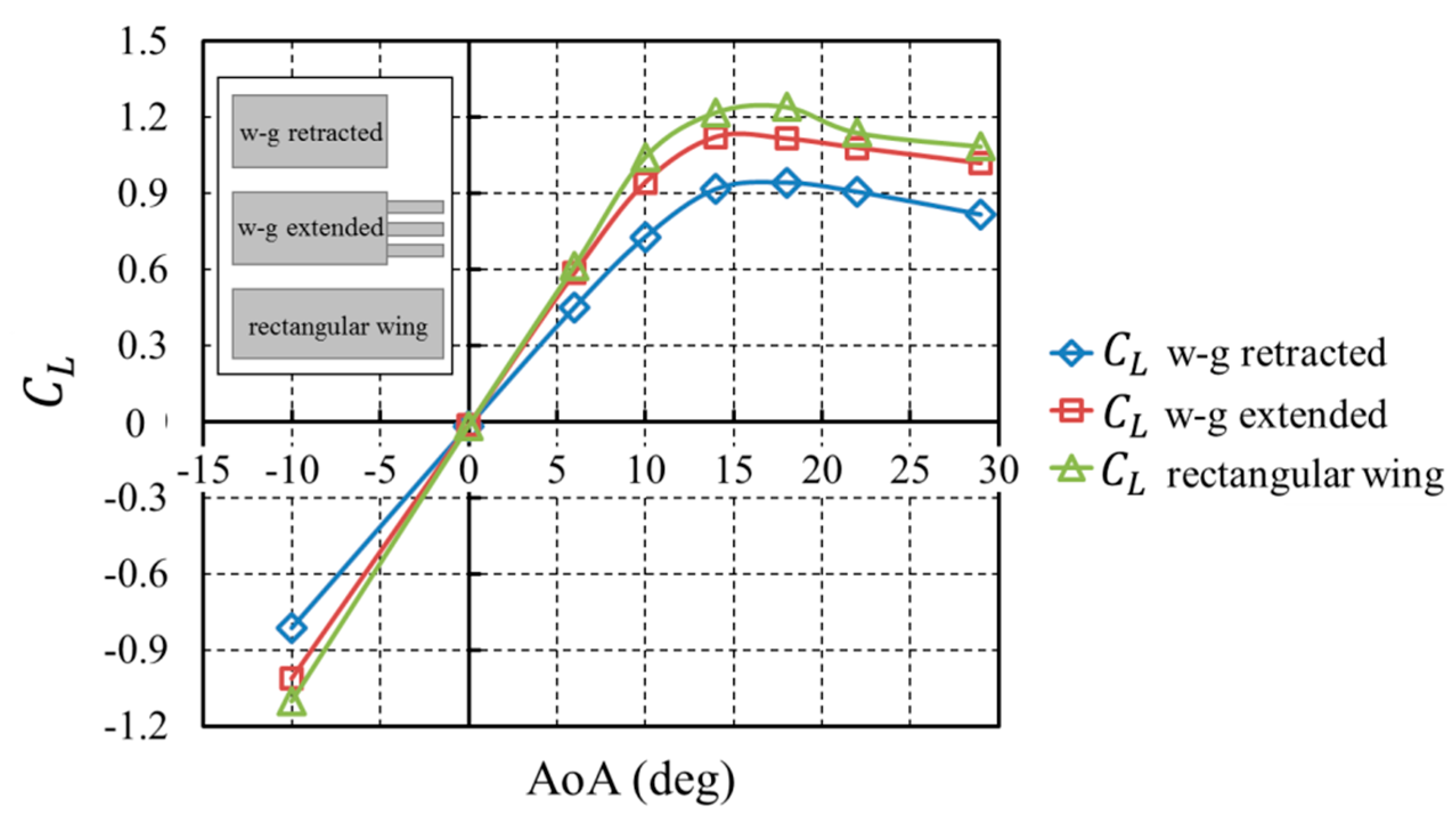
3.1. Wing Grid Vehicle (WGM)

Wind tunnel tests were carried out in the low-speed wind tunnel of the Universidad Politécnica de Madrid (UPM), to obtain the lift coefficient ( C L )   as a function of the angle of attack (Figure 7) and Figure 8 shows the polar curve plotted as the aerodynamic drag coefficient C D   vs. the lift coefficient C L . The configurations studied were: a retracted wing grid, an extended wing grid, and a rectangular wing with the same aspect ratio (AR) as the wing with extended wing grid system. The tests were carried out with a tunnel free stream velocity of 16 m/s, corresponding to a Reynolds number of 9.2 × 10 4 .
The results, in both cases, validate the initial design hypothesis; that is, the deflection and retraction of the wing grid system will modify the characteristics of ( C L ,   C D , C L / C D   ) during the phases of flight.

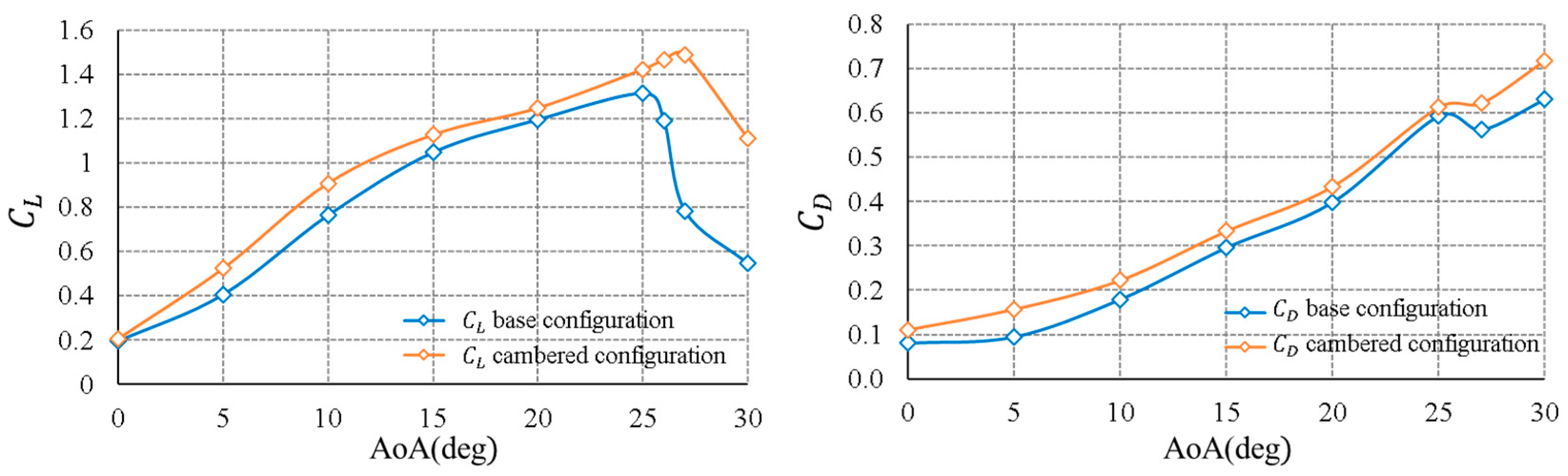
3.2. Morphing-Based Vehicle

Experimental tests are carried out in the low-speed wind tunnel of INTA, with the morphing micro air vehicle (MM) in two different configurations. The vehicle is tested in its base configuration (without wing deformation) and its cambered configuration (with maximum wing deformation). This wind tunnel presents a closed circuit, with an elliptical open test section of 2 × 3 m2. All wind tunnel tests were carried out with an air velocity of the wind tunnel of 10 m/s, which corresponds to a Reynolds number ( R e = 1.30 × 10 5 )   that is a normal operating range for these types of vehicles. The flight conditions ranged from cruise (angle of attack, AoA, α = 0 ° ) to flow-detachment condition at α = 30 ° . The sideslip angle is zero degrees.
The scaled model was built by additive manufacturing, using a low-cost 3D printing machine, in order to obtain a quick response during the wind tunnel test campaign, which reducing manufacturing cost and time. The MAV model was manufactured at full scale, due to its small dimensions compared to the wind tunnel section. The additive material used for this purpose was PLA (polylactic acid), which is a common thermoplastic polymer for wind tunnel testing. The surface of this model was polished to reduce roughness, avoiding any change in the boundary layer. Moreover, the model was painted black to reduce possible laser reflections during the tests.
The aerodynamic coefficients of these MAV configurations were obtained using a balance composed of a XFC300 load cell and a particle image velocimetry (PIV) technique. The model was placed on the wind tunnel platform using a streamlined support strut to reduce possible flow perturbations.
The curves of the lift coefficient (CL) and the drag coefficient (CD), according to the flight condition, are presented in Figure 9.
It can be seen that the lift (CL) in both MAV configurations increases as the angle of attack increases, until reaching the maximum value; from then on, the stall condition takes place, and the lift (CL) decreases rapidly. From this graph, the lift (CL) generated from the MAV with the maximum deformation of the wing is higher than the base configuration for all angles of attack. In this context, the maximum lift coefficient ( C L m a x ) obtained by the cambered configuration is 1.50 at α = 27 ° , while for the base configuration, this lift value is 1.30 at α = 25 ° . If only lift was taken into account in this aerodynamic analysis, the cambered MAV configuration would be the best option and, therefore, would be implemented in all flight conditions. However, an optimal flight requires an optimal aerodynamic efficiency of the MAV in each flight regime, where the lift is maximized as the total drag is minimized. Based on the total drag graph, the drag coefficient (CD) is higher in the MAV with the maximum deformation of the wing for all angles of attack. The MAV in its base configuration should be deployed only in a cruise flight, as the vehicle generates the same lift under cruise conditions with lower drag. However, the MAV in its cambered configuration should be used in landing and take-off maneuvers, as the lift is higher, and the stall angle is delayed (from 25 ° to 27 ° ).

3.3. Aerodynamic Stability Properties

A simplified version of the stability derivatives calculation has been included in Table 1. This method of calculation has been a conventional VLM (Vortex Lattice Method). On the basis of this, a first version of the feasibility of control surfaces and dynamic analysis of the vehicles could be carried out.

4. Command-and-Control Concept

As for the controller, it must be robust enough to maintain stability in the face of atmospheric disturbances (necessary in a very light vehicle), as well as to manage continuous modifications during flight; these modifications produce new configuration parameters of the aircraft system [13], which must be continuously regulated. The fundamentals of the classical system control can generally be applied to the air vehicle. Traditional aircraft attitude control is usually achieved by means of flaps, ailerons, rudders, and control surfaces in general, i.e., mechanical elements that rotate. These elements modify the pressure distribution but typically produce a pressure discontinuity ( C p ). These control surfaces are managed by a flight control computer on board the aircraft.
Within the generic concept of morphing, there are many alternatives, as explained above, acting on the leading edge and the trailing edge, modifying the wing planform, or changing the curvature of the airfoil [11]. The technique of acting on the curvature of the wing morphing is intended to replace the control surfaces of the prototype to control the attitude and speed of the designed drone. In the case of deformable wing geometry control (wing morphing), the geometrical configuration of the wing must be related to the specified flight conditions, to obtain the optimal configuration of the morphing-based flight control. It is necessary to know the actuation level, energy, and control technique used in the maneuver, in order to be able to assert that the adaptive morphing wing geometry modification has sufficient power to perform the maneuvers; it is necessary to know the inertia tensor ( I = ) of the vehicle and the stability characteristics (stability derivatives). The computational capabilities of the flight computer are generally ensured for these levels of drone flight.
Concerning the controller, several traditional control techniques can be considered to design a control computer to act on the mission-adaptive geometry. The design method must allow sufficient flexibility in the adjustment of the wing morphing geometry as well as complex and non-linear dynamics [13,14]. The following aspects must be addressed: linear and nonlinear system behavior, system errors, design condition, aircraft performance, and flight uncertainties. The strong non-linearity of the smart materials and the actuator used to obtain the desired morphing configuration is also included.

4.1. Control Methods

The first approach to calculating the control law is based on the PID estimation. The PID controller’s tuning is the process of finding the proportional, integral, and derivative gain constants to satisfy the desired design and performance requirements. Knowing the gains of this controller is not an easy task. Tuning is usually time-consuming and can cause problems for the system. A good option are methods based on the Ziegler–Nichols method. The feedback system will be a set of different sensors adapted to the wing assembly, either for the morphing wing geometry configuration or for the wingtip device of the wing grid. Figure 10 shows the PID feedback system.
The second suggested method for controlling the shape of the wings is adaptive control. This method is a good control technique to deal with uncertainties. Adaptive control can be adjusted to handle unknown models and environmental uncertainties and to adapt to flight requirements. In this context, direct methods of adaptive control allow an estimation of the parameters to be used in the adaptive controller, and indirect methods are those where the estimated model data are used to tune the controller. Adaptive control (Figure 11) aims to adjust to changes in the system parameters to minimize system error or estimate the change in the control law signal. At the same time, adaptive control can be designed based on a least-squares estimation, a reference model, or dynamic inversion.

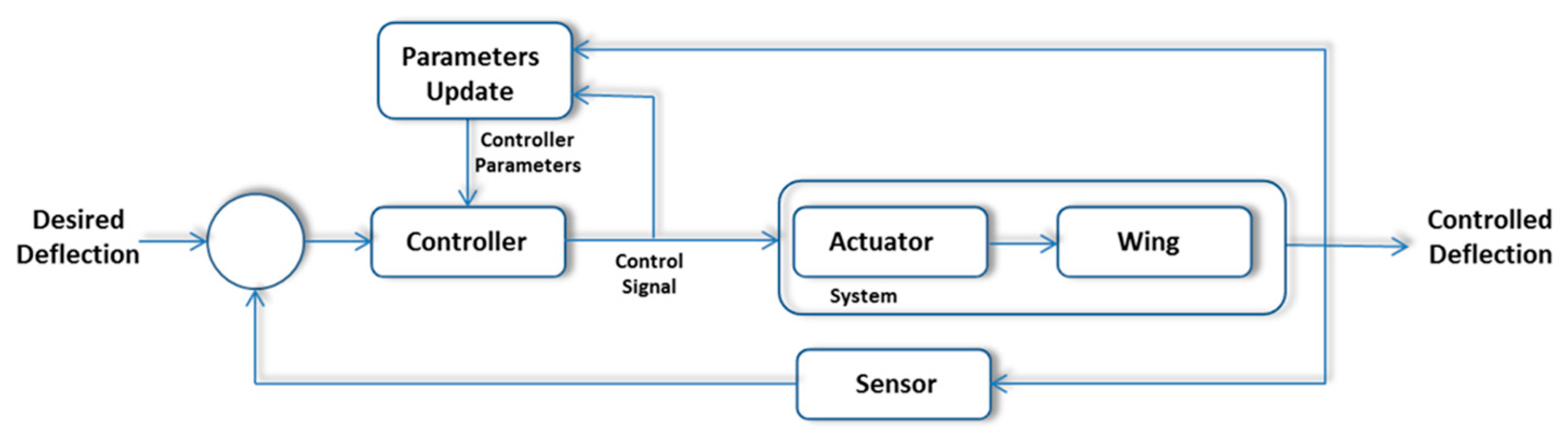
4.2. Control Law for Geometry Morphing

A six-degree-of-freedom (6DOF) dynamic system can represent the equations of motion for the morphing wing of any aircraft. The dynamics of most systems can be represented as a set of second-order differential equations, if the system is expressed in body axes (Equations (4)).
To calculate the control law for the morphing geometry, the system establishes what the feedback information will be from the sensors installed on the aircraft. It must be adequate to obtain position, velocity, and acceleration information as well as the position of the aircraft control surfaces.
All information provided by the sensors shall be used to calculate the system error, in accordance with the system requirements. In the case of the morphing MAV (MM), several control techniques will be evaluated to design the control law.
To further improve the system response, a PID-controlled autopilot [14] must be implemented to complement the stability augmentation system, thus completing the flight control system; a diagram is shown in Figure 12.

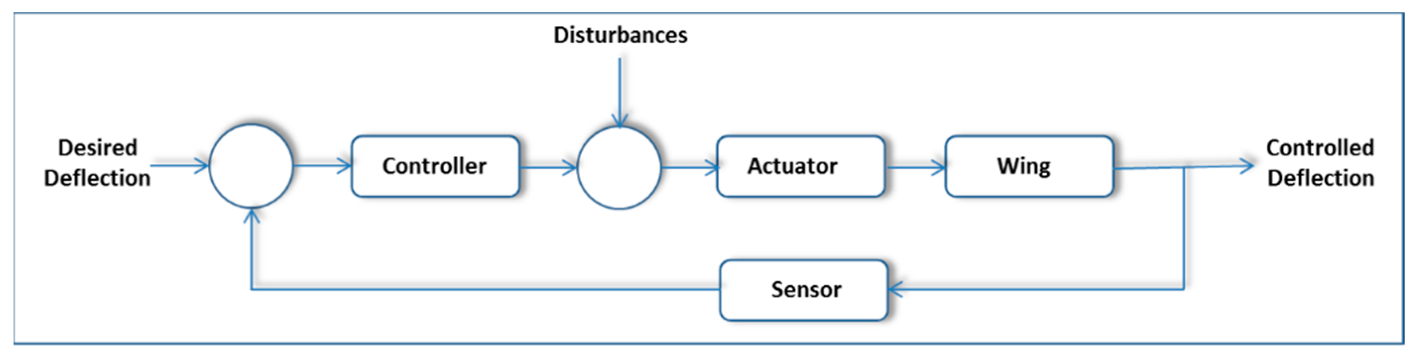
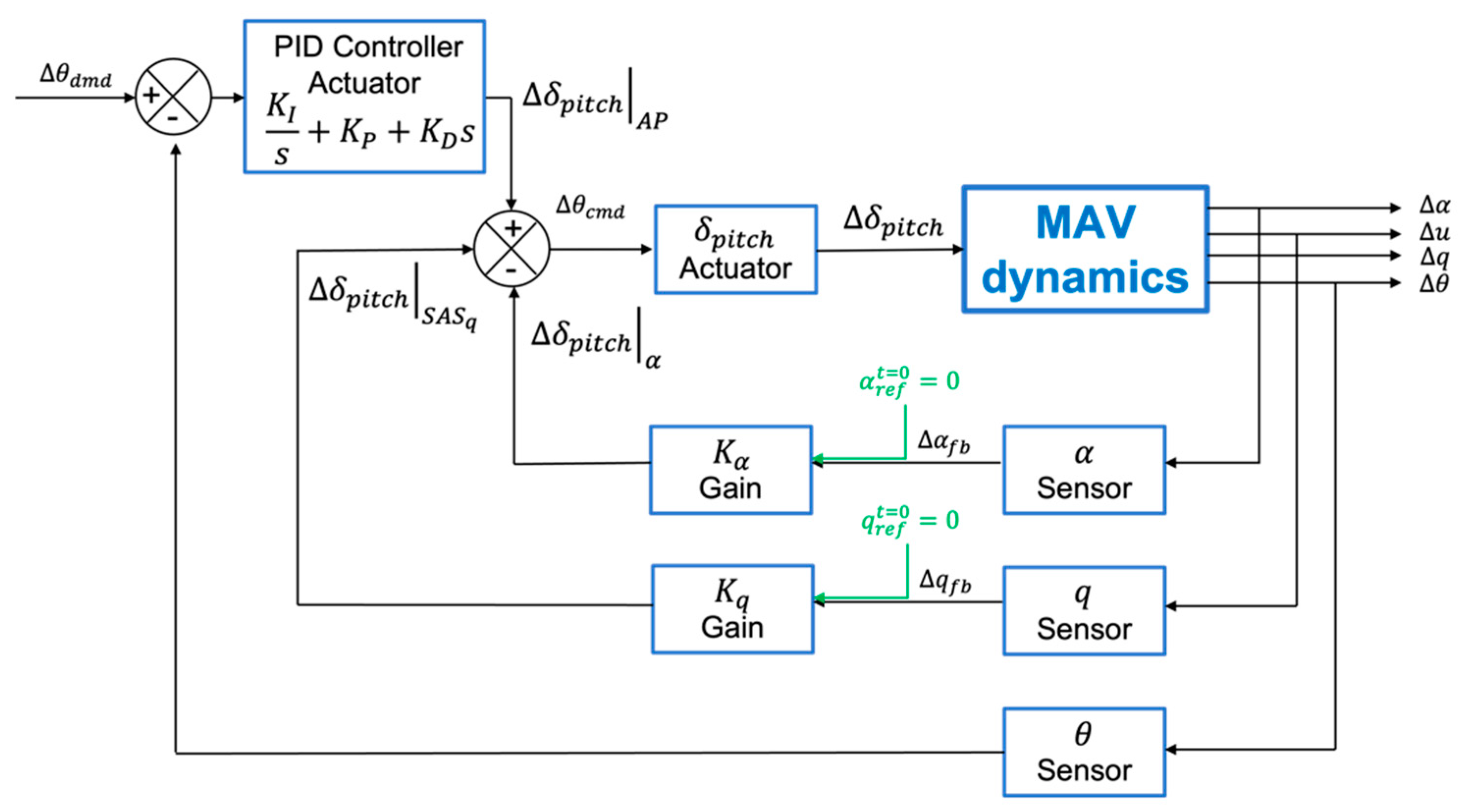
4.3. Feedback System for Morphing MAV (MM)

In the case of the MM prototype, the control of the shape of the aircraft wings is obtained by means of piezoelectric actuators [15,16]. In this aircraft, the use of piezoelectric actuators for wing shape control and static deformation correction is considered the main option to achieve the desired wing shape. The most common methods for controlling the shape of a structure are based on embedded piezoelectric materials. A simple method based on a feedback controller has been used to obtain the optimal wing position and the optimal actuation voltages of the piezoceramic elements. The voltages applied to the piezoceramic elements ( V C O N ) are induced in a defined way to avoid saturation voltages, which are one of the main limitations for their control.
The voltages applied to the piezoelectric elements are considered an open-loop system, where no sensor has been configured to check them. An optimization algorithm has been implemented to calculate the optimal voltages and to control the saturation voltages.
The aim of the actuator and sensor array on the wing is to bend the wing in a controlled manner and maintain the shape of the wing. This sensor, together with the control of the wing shape (curvature), should be considered a closed-loop system. The main function of this system is to maintain airfoil or wing camber (Figure 13) in the presence of unknown (but predictable, with an appropriate safety margin) aerodynamic loads. Therefore, in this design, multiple position sensors on the wing are not required for closed-loop camber control. Figure 14 shows the curvature of the wing as a function of voltage.
On the other hand, in the MAV configuration with a wing grid system, the wing geometry is modified with extensions in the original wing to substantially change the aerodynamics of the vehicle and, at the same time, have the attitude control (in balance) of the aircraft; in this case, the deployment will be achieved by means of an endless spindle for its displacement.

5. Practical Aspects

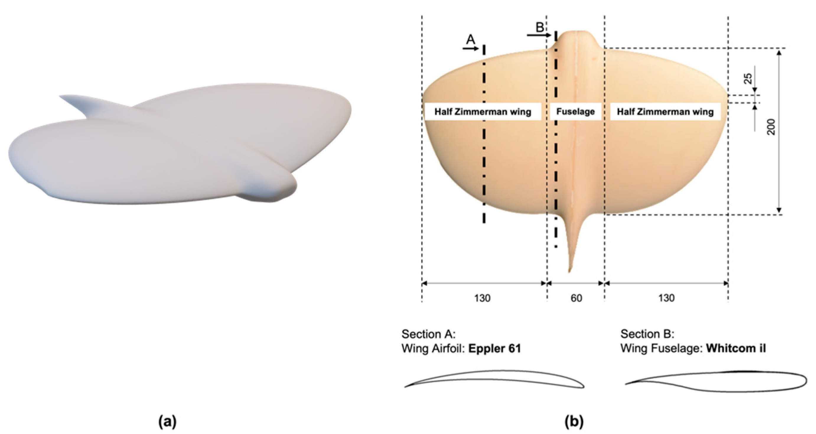
5.1. Configuration and Dimensions of Each Prototype

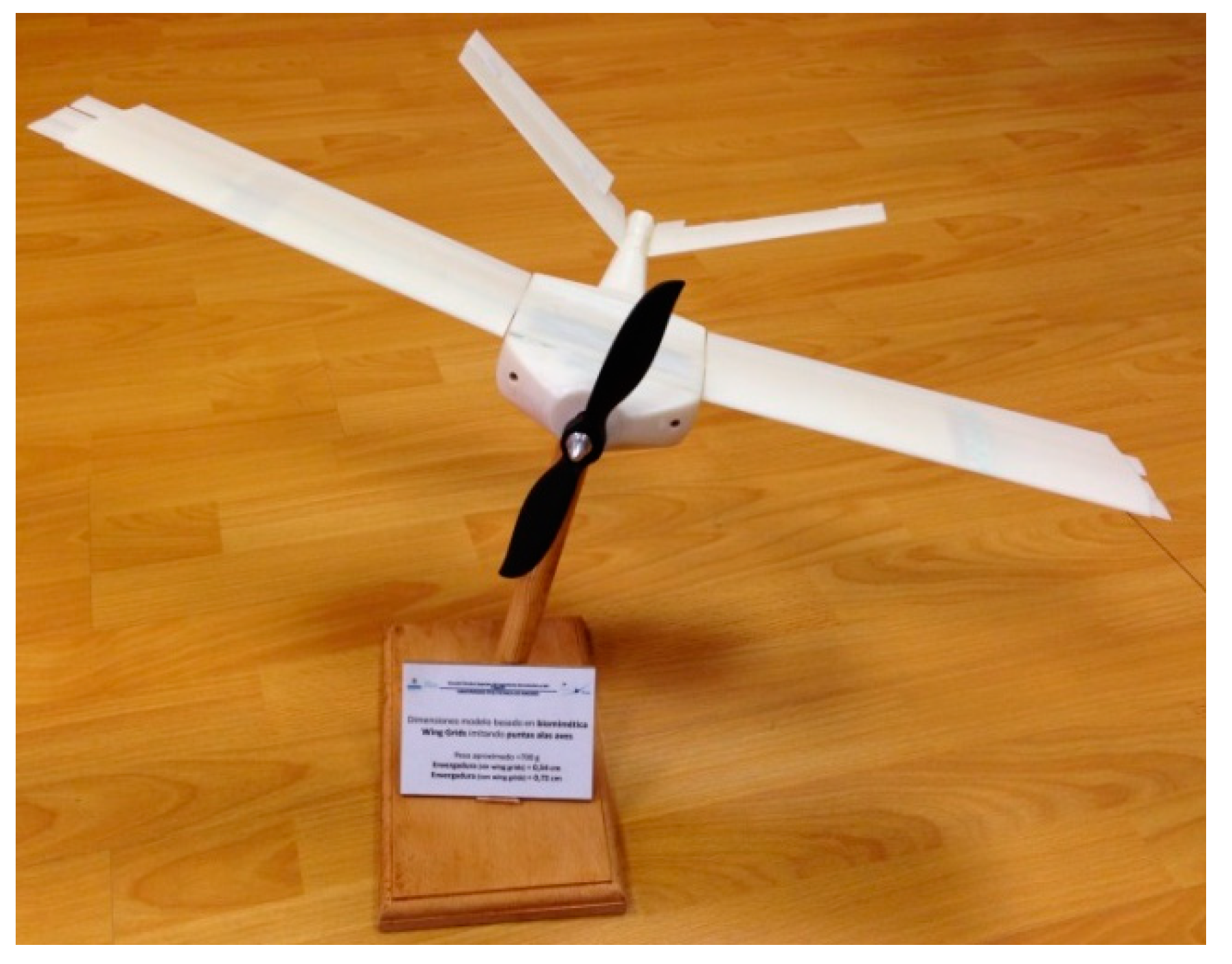
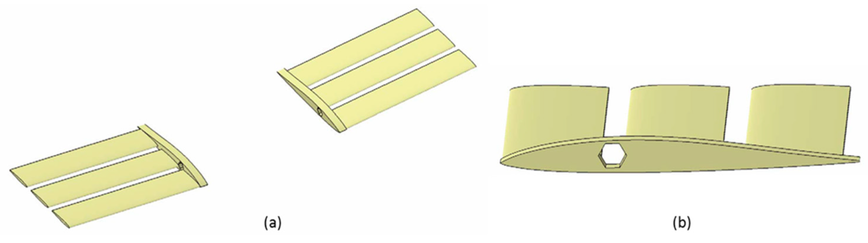
5.1.1. Wing Grid Prototype (WGM)

The dimensioning of the aerodynamic surfaces (wing grid) that define the MAV prototype (WGM) is the essential criterion in the definition of it.
The possible configurations analyzed for the wing prototype are presented below:
  • Base configuration: The wing grid system was fully retracted. In the aerodynamic study, this was the base configuration or the reference configuration. In a flight with this configuration, the balance control would be exclusively with the tail surfaces.
  • Cruise configuration: The fully deployed wing grid system. Bennet [6] proved in a wind tunnel that the use of the deployed configuration at low angles of attack is more appropriate than at high angles of attack, where the aerodynamic efficiency is halved. They may be more suitable for cruise conditions. The deployment of the symmetrical wing grid increases the wingspan, with a consequent increase in the coefficient of lift ( C L ) as well as a reduction in the coefficient of induced drag ( C D i ), with all other flight conditions being equal.
  • Rolling configuration: When a wing grid system is deployed antisymmetrically, one half-wing is retracted, and the other half-wing is deployed. An asymmetric lift distribution is generated ( C l w i n g   g r i d   d e p l o y m e n t ) , and the vehicle rolls ( ϕ ) right or left. This provides the MAV (WGM) with the roll control that would normally be given by the ailerons.
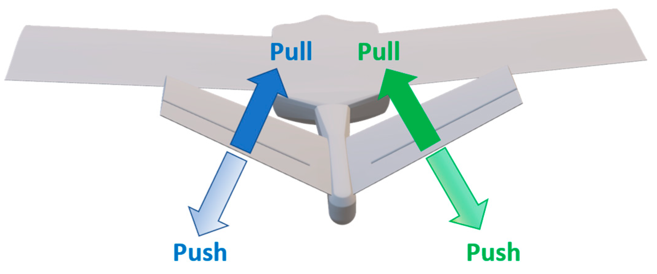
  • Yawing/pitching configuration: A V-tail was chosen to control yaw ( ψ ) and pitch ( θ ) , instead of using the conventional configuration of horizontal and vertical stabilizers. The main dimensions and characteristics of the MAV are shown in Table 2 [3]. Figure 15 includes a description of the control surfaces in the V-tail, and the effects on the MAV attitude are described in Table 3.
The wing grid assembly is made up of three elements that are joined by means of the base of the winglets (or a base profile), as shown in Figure 16.
The first prototype tested in our testbed is a 1.5:1 scale reproduction of the original MAV. The demonstrator is scaled to have enough space to accommodate all the necessary elements. More information about the features of the model can be found in [3].

5.1.2. Morphing Prototype (MM)

The possible configurations analyzed for this prototype are presented below:
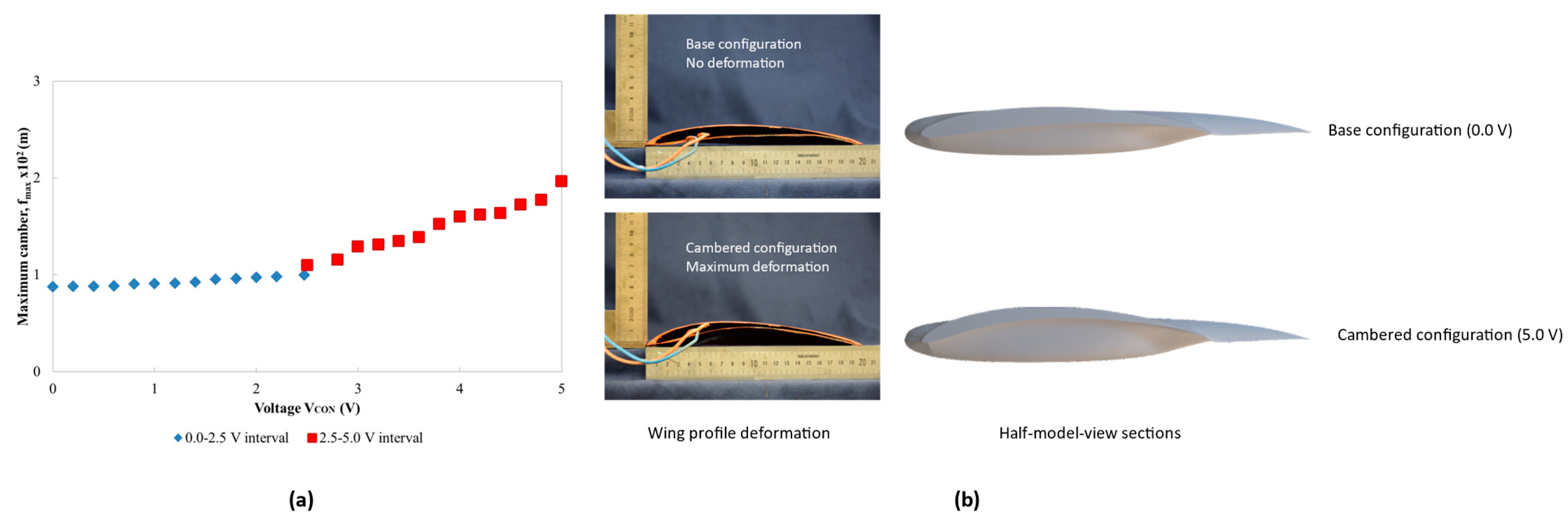
  • Base configuration: The morphing system is without any curvature deformation (0.0 V). In the aerodynamic study, this was the base configuration or the cruise configuration.
  • Pitching configuration: Morphing properties (curvature) were controlled asymmetrically in each half-wing, generating the same effect (pitch angle, θ ) such as a conventional elevator   ( δ p i t c h ) . If necessary, a pitch rate ( q ˙ )   also appears.
The dimensions and main characteristics of the prototype verified in the testbed are shown in Table 4.
In this case, the prototype tested maintains the dimensions of the original one.

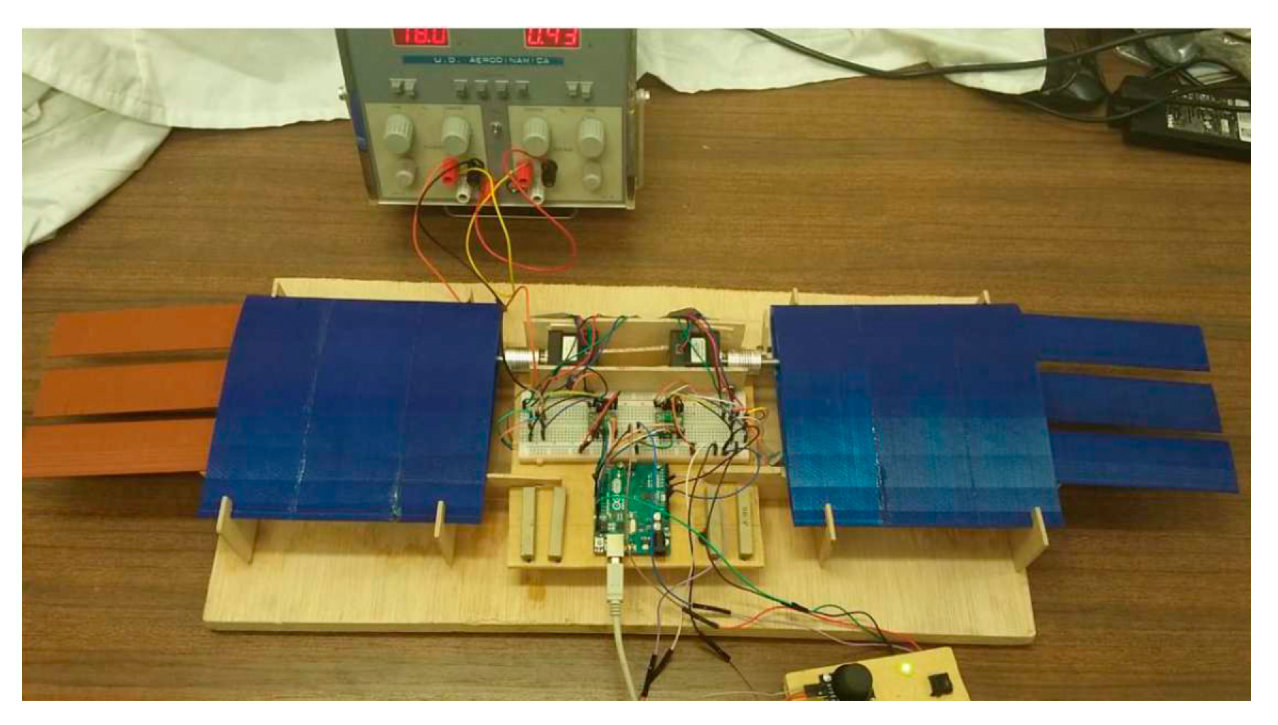
5.2. Testbed Configuration

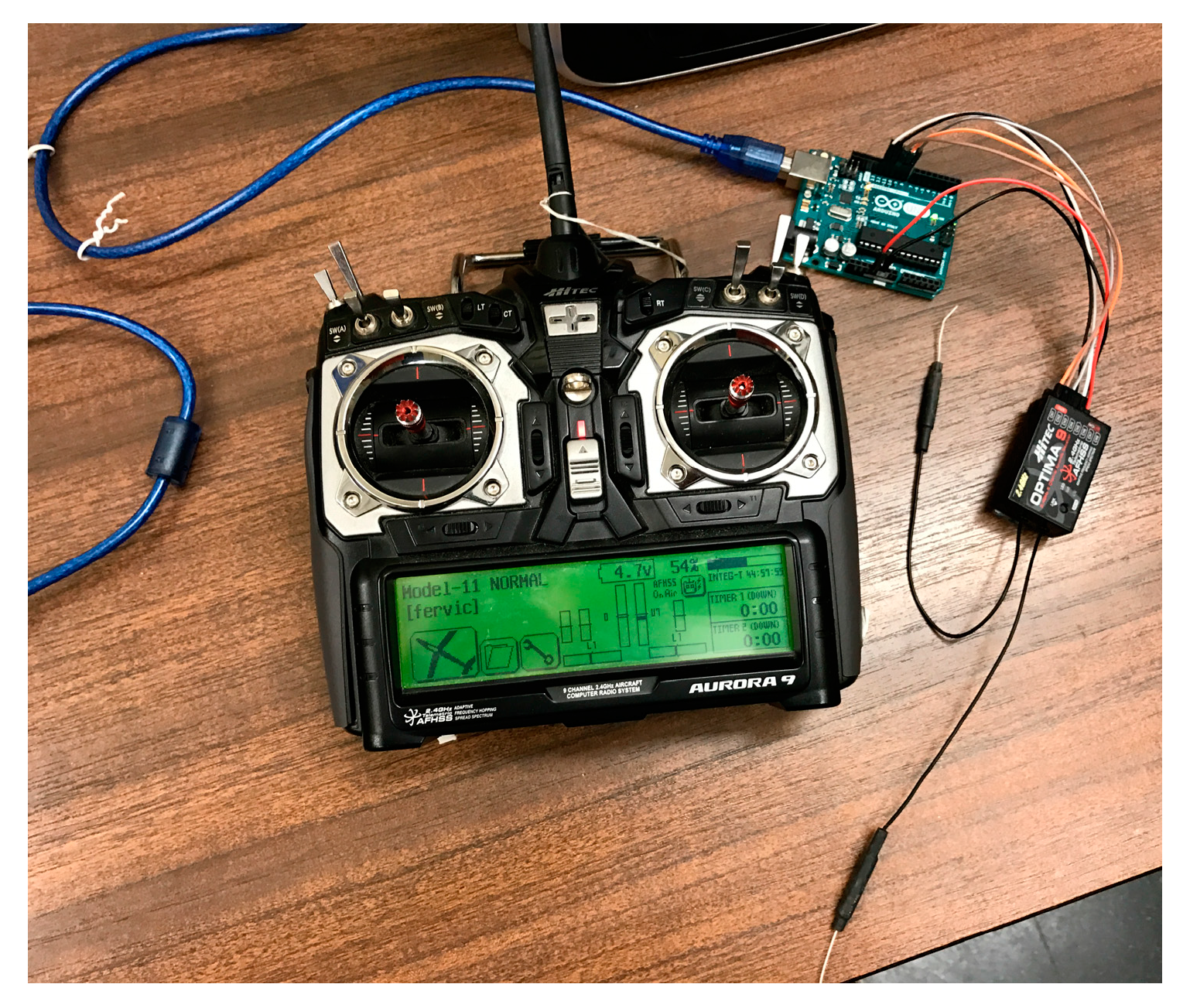
5.2.1. WGM Hardware Testbed

The control system was designed to provide the MAV with the ability to modify its configuration, as detailed above. The following is a brief description of the hardware and software elements used.
The project was primarily based on Arduino technology [17], as it is a widely used, open-source, and low-cost platform. The software used to write and implement the code was the Arduino programming language and the Arduino software (IDE).
The model chosen for the initial prototype was Arduino Uno, due to its small dimensions, but Arduino Mega might be a better choice for future progress due to its larger number of pins. For the WGM prototype, where a minimum size was required, the Arduino Micro was selected after analyzing the number of pins needed for all elements. The Arduino Micro is smaller than the Uno and Mega boards and provides the necessary I/O ports for all systems.
Several alternatives were considered to select the motor to control the wing grid device. For our first testbed prototype, a Pololu NEMA 14 bipolar stepper motor was chosen [18]. This initial test model is larger than the original design, to avoid problems caused by the dimensions of the motor. This type of electric motor has two main characteristics: the precision to stop its movement at any given angle (like a servo motor), and the ability to change the direction of rotation (like a DC motor). In addition, the chosen motor is bipolar rather than unipolar, due to its higher torque. For the second testbed prototype, the stepper motor selected was a NEMA 8. Although this motor provides less torque than a NEMA 14, the torque is sufficient for the displacement of the wing grid device. In this second testbed, a remote communication system has been implemented. For this purpose, a conventional hobby RC model aircraft has been used. The RC receiver transmits the pilot command information from the RC transmitter to the Arduino board (Figure 17). Pilot input is processed to achieve open-loop control of the MAV.

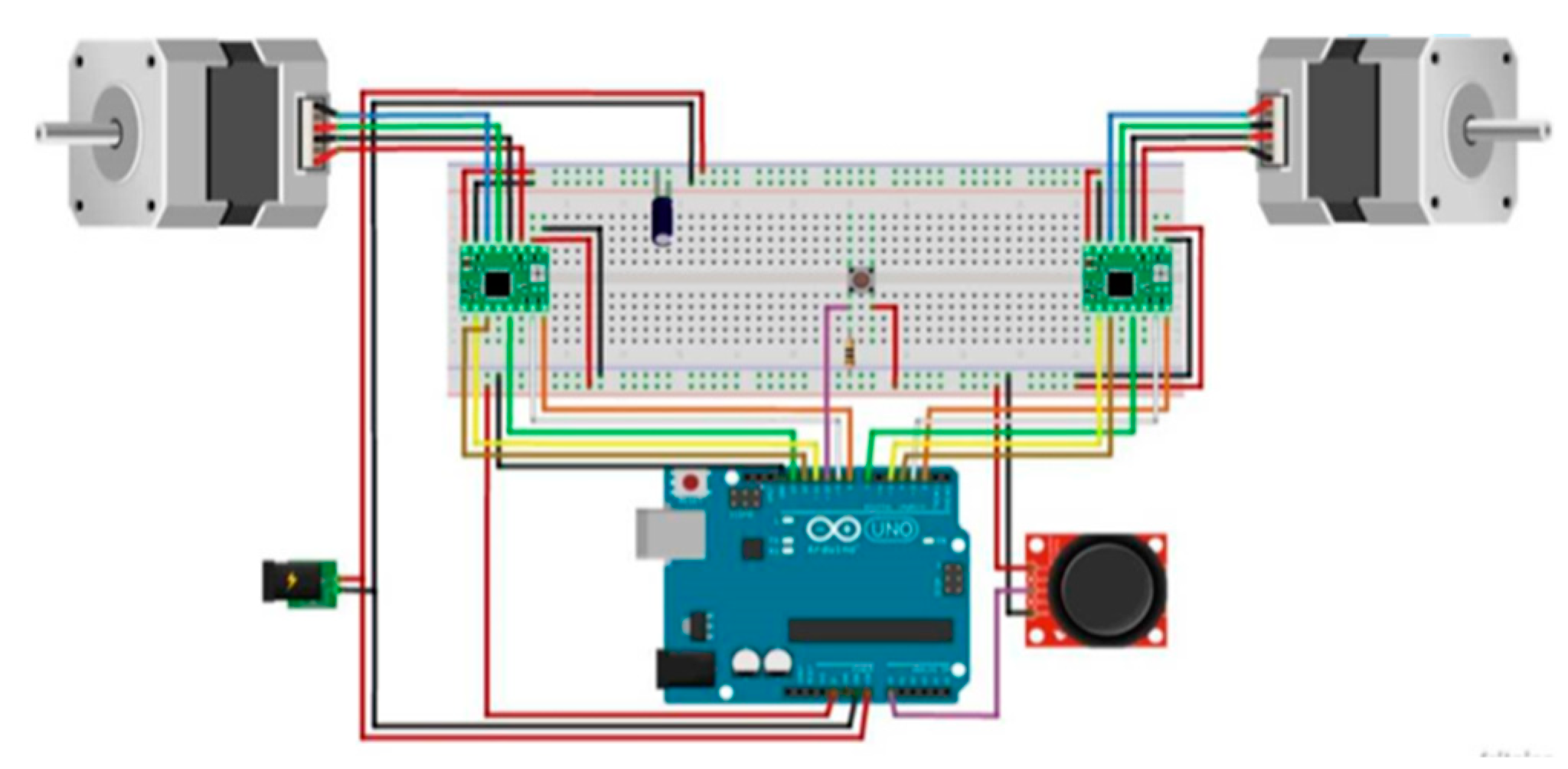
5.2.2. Transmission Mechanism

To transform rotation into translation, the classic solution of a nut and a threaded spindle mechanism was proposed. The spindle is connected to the motor shaft with an aluminum coupler. Given the length of the wing grid system (L ≈ 150 mm), the time required to change the configuration from fully retracted to fully deployed is calculated in Table 5.
To solve this problem, a 25.4 mm spindle was used in the prototype.

5.2.3. Connection Details

Following the same calculation as above, the full deployment time is less than 3 s, and the final travel of the elements will be 135 mm.
Figure 18 is a schematic electrical diagram of the wiring designed to control the wing grid system. On the one hand, the power supply powers the Arduino Uno by connecting the positive electrode to the Vin pin and the negative electrode to the GND pin. To power the motors, the supply is connected to the drivers on pins Vm and GND (positive and negative electrodes, respectively), and, these, in turn, are connected by pins 1a, 1b, 2a, and 2b to the stepper terminals. The operating voltage of the motors should be within the range of 8–35 V and that of the Arduino Uno within the range of 7–12 V. Specifically, 12 V corresponds to the supply voltage used in the tests (the motors run on 2.7 V, but there is compatibility due to the current limiting feature of the drivers, as previously explained).
On the other hand, the Arduino Uno works as a power supply for some elements. The logic power for the drivers (3–5.5 V) is provided by the 5 V pin of the Arduino Uno, connected to the Vdd pin of the drivers. It also supplies the joystick and switch.
There is a set of connections between the Arduino Uno and the driver necessary to configure the steppers: direction of rotation, microstepping and, essentially, pulse control.
If joystick is replaced, the wiring for the control of the wing grid is like the one depicted in Figure 18. The RC receiver replaces the joystick and switch as the control input of the wing grid, while the Arduino board is connected to the servo motors and the ESC to achieve a V-tail. The servomotors are also connected to the power distribution board at the 5 V output.
From the hardware selections, linear functions will be available for each lecture of channel 1, (Lecchannel_1), and it will assign a required position (posdem) of the wing grid (left or right), that is, a specific number of steps of one of the motors. These functions have been included in Table 6.

5.2.4. Software Algorithm

In the initial tests, a joystick was proposed to transmit the commands to the Arduino Uno. The idea was to linearly correspond the position of the joystick with the position of the wing grid, which is the number of steps of the motors. A margin of error (±50 steps) was set to avoid accuracy problems; with this decision, small variations in the position of the joystick may not produce variations in the position of the wing grid. Furthermore, by means of a switch, the setting can be changed from cruise to non-cruise or vice versa.
At this point, a brief explanation of the functional analysis of the code is necessary. The code is divided into two basic configurations: fully retracted wing grid assembly and fully deployed wing grid assembly. From each base configuration, all possible combinations of the position of the wing grid device are covered by conditional loops. To change the two base configurations, the switch value changes when pressed from 0 to 1 or vice versa, giving the Arduino Uno information on the current configuration. This algorithm could be resumed in Figure 19.
The control proposed for the initial testing was modified in the second prototype. The previous joystick and switch inputs are replaced by two channels of RC equipment. The RC transmitter that controls the wing grid system is shown in Figure 20.
In our third future prototype, the V-tail will be commanded from the input of the rudder and elevator channels. On the Arduino board, both input signals are processed and combined to achieve, using the V-tail, the same output as that obtained using the classic rudder and elevator (Figure 15, Table 3).

5.2.5. Model Assembly

The design of the wings and wing grid devices of the first prototype was based on a previous project; see details in [3]. Additive printing (3D printing) technology was used to make the model. Due to the size limitations of the printing machine, several modifications to the original design were required (see configuration and dimensions section). Polymeric adhesive was used to bond the structural elements.
Additionally, a wooden base was designed and constructed for the structural integration of the wing, the wing grid, and the hardware elements for ease of use and to allow repetitive and solid movement. The result is shown in Figure 21.

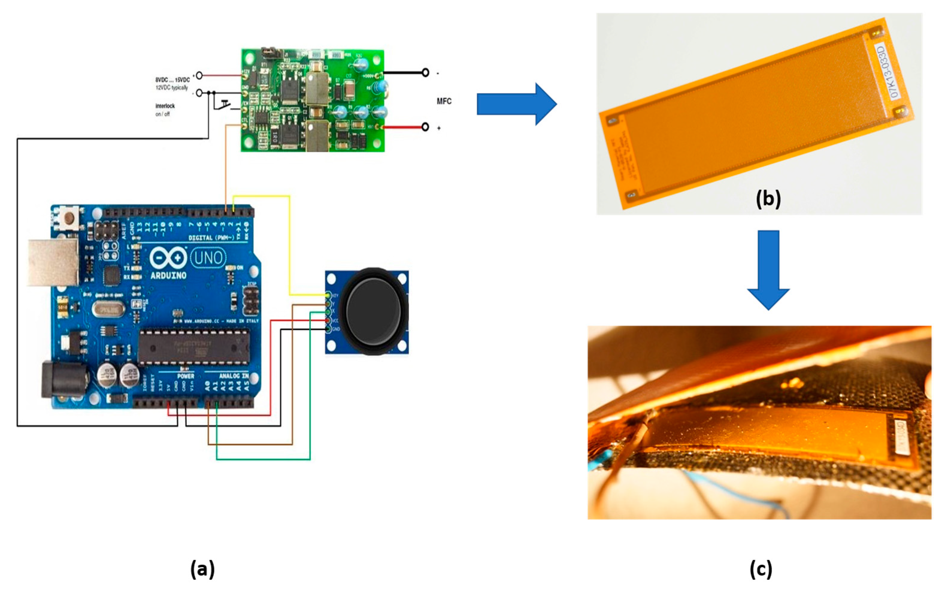
5.3. Morphing Testbed

Figure 22 shows the main schematic of the morphing prototype. All the elements of the prototype are included, that is, the control device, the Arduino board, the amplifier, the MFC, and the detail of the MFC installed on the lower part of the wing.
On the one hand, the joystick has five outputs that are all connected to different pins on the board. Two of these outputs are those corresponding to ground (GND) and power, which are connected to the GND and 5 V pins, respectively. The three remaining outputs are those associated with the displacement of the x- and y-axis as well as the button. The axes outputs are connected to pins A0 and A1, which, as previously indicated, are analog input pins. The pushbutton, however, must be connected to a digital pin, in this case number two.
On the other hand, there is the MFC amplifier that is connected to the GND pin and to pin number three. This pin must be explicitly declared as an output in the code and, through its actuation, Arduino will provide the signal that will be sent to the actuators through said amplifier.

6. Conclusions

This work presents the control system of two MAV (MM, WGM) models based on bioinspiration; a model (MM) with variable wing geometry (morphing), and a second model (WGM) with wingtips that are deployable in flight, imitating the feathers of large gliding birds. In both cases, the aim is to modify the wing geometry to adapt it to flight requirements. A brief introduction was given to explain the aerodynamic characteristics provided by both solutions, which will potentially lead to a solution with the proposed requirements.
Once the geometrical characteristics have been described, their aerodynamic characteristics have been analyzed, and how their variations would influence their performances have been assessed, we proceeded to define the characteristics of the hardware (control board, actuators, motion sensors) and software of both MAV models. To show the feasibility of these MAVs, two testbeds with the same hardware have been built and tested. The electronic devices are described in detail, explaining the selection criteria. The concept of programming the code to achieve symmetric and antisymmetric maneuvers is shown.
The WGM testbed was manufactured using 3D printing. This printing process has allowed any complex wing geometry to be manufactured with versatility and, at the same time, at a very low cost; in this case, it is the optimal manufacturing process, because the models do not need demanding structural requirements. The materials used to include modifications to the wings are polymers that are well-adapted to change their external configuration and provide adequate strength and stiffness to fly in the required flight conditions.
With these testbeds, the control capabilities of both wing systems were demonstrated with simple control and, at a high level of complexity, with an RC transmitter.
Future work will focus on increasing the size of the models, including the rest of the systems of the MAVs, and designing an automatic flight control system for pitch control (MM) and for V-tail capabilities (WGM). Then, the final prototypes will be able to make their first flight.

Author Contributions

Conceptualization, R.B.-M., Á.A.R.-S. and J.C.-M.; methodology, R.B.-M., Á.A.R.-S. and J.C.-M.; software, J.C.M.-G. and E.B.-B.; validation, R.B.-M., Á.A.R.-S., J.C.-M., J.C.M.-G. and E.B.-B.; formal analysis, R.B.-M., Á.A.R.-S., J.C.-M., J.C.M.-G. and E.B.-B.; investigation, R.B.-M., Á.A.R.-S., J.C.-M., J.C.M.-G. and E.B.-B.; resources, J.C.M.-G. and E.B.-B.; data curation, R.B.-M., Á.A.R.-S., J.C.-M., J.C.M.-G. and E.B.-B.; writing—original draft preparation, R.B.-M., Á.A.R.-S., J.C.-M., J.C.M.-G. and E.B.-B.; writing—review and editing, R.B.-M., Á.A.R.-S., J.C.-M., J.C.M.-G. and E.B.-B.; visualization, R.B.-M.; supervision, R.B.-M.; project administration, R.B.-M.; funding acquisition, R.B.-M. All authors have read and agreed to the published version of the manuscript.

Funding

This research received no external funding.

Institutional Review Board Statement

Not applicable.

Informed Consent Statement

Not applicable.

Data Availability Statement

Not applicable.

Acknowledgments

The authors thank all the engineers and analysts from the Department of Aerodynamics of the ‘Instituto Nacional de Técnica Aeroespacial Esteban Terradas’ (INTA) and the enthusiastic efforts of D. Arrones, M. Barcala, C. Cabaleiro, A. Cobo, I. Díaz, A. Navío, R. Ribate, A. Romero, D. Shportenko, and E. Sánchez from the Escuela Técnica Superior de Ingeniería Aeronáutica y del Espacio.

Conflicts of Interest

The authors declare no conflict of interest. The funders had no role in the design of the study; in the collection, analyses, or interpretation of data; in the writing of the manuscript; or in the decision to publish the results.

References

  1. Sofla, A.Y.; Meguid, S.A.; Tan, K.T.; Yeo, W.K. Shape morphing of aircraft wing: Status and challenges. Mater. Des. 2010, 31, 1284–1292. [Google Scholar] [CrossRef]
  2. Li, D.; Zhao, S.; da Ronch, A.; Xiang, J. A review of modelling and analysis of morphing wings. Prog. Aerosp. Sci. 2018, 100, 46–62. [Google Scholar] [CrossRef]
  3. Rodríguez-Sevillano, Á.A.; Barcala Montejano, M.A.; Bardera Mora, R.; León-Calero, M.; García-Ramírez, J.; de Nova-Trigueros, J. Biomimetic micro air vehicle controlled by wing-grids. In Proceedings of the 8th Conference on Smart Structures and Materials, SMART 2017 and 6th International Conference on Smart Materials and Nanotechnology in Engineering, SMN, Madrid, Spain, 5–8 June 2017; Volume 2017, pp. 413–423. [Google Scholar]
  4. La Roche, U.; La Roche, H.L. Induced drag reduction using multiple winglets, looking beyond the Prandtl-Munk linear model. In Proceedings of the 2nd AIAA Flow Control Conference, Portland, OR, USA, 28 June–1 July 2004. [Google Scholar]
  5. Bennett, D. The Wing-Grid: A New Approach to Reducing Induced Drag; Massachusetts Institute of Technology: Cambridge, MA, USA, 2001. [Google Scholar]
  6. Tucker, V.A. Gliding birds: Reduction of induced drag by wing tip slots between the primary feathers. J. Exp. Biol. 1993, 180, 285–310. [Google Scholar] [CrossRef]
  7. Mohamed, A.; Watkins, S.; Clothier, R.; Abdulrahim, M.; Massey, K.; Sabatini, R. Fixed-wing MAV attitude stability in atmospheric turbulence—Part 2: Investigating biologically-inspired sensors. Prog. Aerosp. Sci. 2014, 71, 1–13. [Google Scholar] [CrossRef]
  8. Valasek, J. Morphing Aerospace Vehicles and Structures; John Wiley and Sons: Hoboken, NJ, USA, 2012. [Google Scholar]
  9. Cook, M.V. Flight Dynamics Principles: A Linear Systems Approach to Aircraft Stability and Control; Butterworth-Heinemann: Waltham, MA, USA, 2012. [Google Scholar]
  10. Nelson, R.C. Flight Stability and Automatic Control; WCB/McGraw Hill: New York, NY, USA, 1998; Volume 2. [Google Scholar]
  11. Barcala-Montejano, M.A.; Rodríguez-Sevillano, Á.A.; Crespo-Moreno, J.; Bardera-Mora, R.; Silva-González, A.J. Optimized performance of a morphing micro air vehicle. In Proceedings of the 2015 International Conference on Unmanned Aircraft Systems (ICUAS), Denver, CO, USA, 9–12 June 2015; pp. 794–800. [Google Scholar]
  12. Kroo, I. Drag due to lift: Concepts for prediction and reduction. Annu. Rev. Fluid Mech. 2001, 33, 587. [Google Scholar] [CrossRef]
  13. Pratt, R.W. Flight Control Systems, Practical Issues in Design and Implementation; The Institute of Electrical Engineers: Stevenage, UK, 2000; pp. 119–167. [Google Scholar]
  14. Bardera, R.; Crespo, J.; Rodríguez-Sevillano, Á.A.; Muñoz-Campillejo, J.; Barderas, E.B.; Cobo-González, Á. Design of a flight control system for a bioinspired drone. In Proceedings of the AIAA AVIATION 2022 Forum, Chicago, IL, USA, 27 June–1 July 2022; p. 3389. [Google Scholar]
  15. Gomez, J.C.; Garcia, E. Morphing unmanned aerial vehicles. Smart Mater. Struct. 2011, 20, 103001. [Google Scholar] [CrossRef]
  16. Barcala-Montejano, M.A.; Rodríguez-Sevillano, Á.A.; Bardera-Mora, R.; García-Ramírez, J.; de Nova-Trigueros, J.; Urcelay-Oca, I.; Morillas-Castellano, I. Smart materials applied in a micro remotely piloted aircraft system with morphing wing. J. Intell. Mater. Syst. Struct. 2018, 29, 3317–3332. [Google Scholar] [CrossRef]
  17. Available online: https://www.arduino.cc (accessed on 30 July 2022).
  18. Riba Pololu Robotics & Electronics. Stepper Motor: Bipolar, 200 Steps/Rev, 35 × 36 mm, 2.7V, 1 A/Phase. Available online: https://www.pololu.com/product/1209/specs (accessed on 30 July 2022).
Figure 1. Typical flight profile.
Drones 06 00248 g001
Figure 2. Conventional nomenclature in the motion of air vehicles.
Drones 06 00248 g002
Figure 3. Design concept of a bioinspired MAV (MM) morphing, based on smart materials.
Drones 06 00248 g003
Figure 4. MAV model (MM) with morphing wings: (a) 3D view; (b) main dimensions.
Drones 06 00248 g004
Figure 5. MAV prototype with wing grid concept (WGM).
Drones 06 00248 g005
Figure 6. MAV prototype (WGM) showing wing grid details (in red color). (A) 3D view with wing grid extended; (B) Main dimensions of the MAV and wing grid properties; (C) Wing grid with different grid spans (base, b/3, 2b/3, and b).
Drones 06 00248 g006
Figure 7. C L   as a function of α (AoA) in the three configurations: retracted wing grid, extended wing grid, and rectangular wing.
Drones 06 00248 g007
Figure 8. Polar curve of the three MAV configurations: retracted wing grid, extended wing grid, and rectangular wing.
Drones 06 00248 g008
Figure 9. Lift coefficient CL (left) and drag coefficient CD (right) vs. angle of attack for the base configuration (without wing deformation) and the cambered configuration (maximum wing deformation) of the MAV.
Drones 06 00248 g009
Figure 10. A simplified diagram of the feedback control.
Drones 06 00248 g010
Figure 11. A simplified version of the adaptive control diagram.
Drones 06 00248 g011
Figure 12. Final objective of the pitch angle autopilot flight control system. More details in [14].
Drones 06 00248 g012
Figure 13. Geometrical properties in a conventional airfoil.
Drones 06 00248 g013
Figure 14. Variation of wing curvature in MM prototype with voltage. (a) Relationship between the curvature of the wing and the control of the main voltage piezoelectric device; (b) deformation of the wing of the prototype in the testbed.
Drones 06 00248 g014
Figure 15. Surfaces of control in the V-tail (ruddervators).
Drones 06 00248 g015
Figure 16. Exploded view of the Wing grid system. (a) Wing grid; (b) detail of the hole in the root, where the bolt from the deployment mechanism will fit.
Drones 06 00248 g016
Figure 17. Main assembly of the RC and the Arduino board to test the code.
Drones 06 00248 g017
Figure 18. Schematic electrical diagram of the wiring designed to control the testbed of the wing grid prototype.
Drones 06 00248 g018
Figure 19. Descriptive diagram of the operation of the control software for WGM MAV.
Drones 06 00248 g019
Figure 20. RC equipment of two channels. (a) Control of symmetric retraction-extension of the wing grid prototypes; (b) control of nonsymmetric deployment of the wing grid prototypes.
Drones 06 00248 g020
Figure 21. Testbed of the prototype of the wing grid and the control system.
Drones 06 00248 g021
Figure 22. Main schematic of the morphing prototype. (a) Electrical wiring; (b) smart material; (c) detail of smart material installed on the lower part of the wing (inside view).
Drones 06 00248 g022
Table 1. Stability derivatives of the different MAV.
MAV ModelVersionStability Derivative
Coefficient
Value (rad−1)Flight Condition
(Speed m/s)
MMBaseline C L α
C m α
C l δ
2.196
0.728
0.040
10.3
MMMaximum
deformation
C L α
C m α
C l δ
2.054
0.737
0.068
9.1
WGMWG retracted C L α
C m α
C l δ
C l   W G d
4.801
−0.151
−0.069
NP
15.4
MMWG extended C L α
C m α
C l δ
C l   W G d
6.311
−0.276
−0.070
−0.002
15.4
Table 2. Characteristics of the original MAV model.
MagnitudeWingWing Grid
(One Element)
Wing + Wing GridV-Tail
Span (mm)540180720250
Mean   aerodynamic   chord   c ¯   (mm)90209060
Area   ( mm 2 )48,600360064,80015,000
AR6983
Λ1/4 (°)0006
Table 3. Displacements of the control surfaces of the V-tail and their effect on the MAV attitude.
Change in MAVLeft RuddervatorRight Ruddervator
Tail right
Nose left
PullPush
Tail left
Nose right
PushPull
Tail up
Nose down
PullPull
Tail down
Nose up
PushPush
Table 4. Main geometrical properties of the MAV prototype morphing (MM).
ParameterValue
Chord   at   the   tip   of   the   wing ,   c t 0.025   m
Chord   at   wing   root ,   c r 0.200   m
Taper ratio, λ0.124
Aspect   ratio ,     A R 2.500
Wingspan ,     b 0.320   m
Mean aerodynamic chord 0.141   m
Mean   geometry   chord ,   C M G 0.127   m
Wing   reference   area ,   S 0.040   m 2
Dihedral angle 10 °
Fuselage length, l 0.3   m
Fuselage width, d 0.06   m
Table 5. Technical characteristics of the NEMA 14 motor.
VariableData
n (rotational speed of the motor)150 rev/20 s = 450 rpm
A (feed) = p·e1 mm
Va (feed rate) = A·n7.5 mm/s
t (time) = L/Va20 s
Table 6. Relationship between lectures from channel 1 and demanded positions.
Turn DirectionDeploymentFunction
LeftRetracted p o s d e m = 1.6 · ( L e c c h a n n e l _ 1 1460 )
RightRetracted p o s d e m = 1062.99 2.013 · ( L e c c h a n n e l _ 1 912 )
LeftExtended p o s d e m = 1062.99 1.6 · ( L e c c h a n n e l _ 1 1460 )
RightExtended p o s d e m = 2.013 · ( L e c c h a n n e l _ 1 912 )
Publisher’s Note: MDPI stays neutral with regard to jurisdictional claims in published maps and institutional affiliations.

