Abstract

Inductive Sensor with Contactless Interrogation for Conductive Target Detection †

Department of Information Engineering, University of Brescia, 25123 Brescia, Italy
*
Author to whom correspondence should be addressed.
Presented at the XXXV EUROSENSORS Conference, Lecce, Italy, 10–13 September 2023.
Proceedings 2024, 97(1), 95; https://doi.org/10.3390/proceedings2024097095
Published: 25 March 2024
(This article belongs to the Proceedings of XXXV EUROSENSORS Conference)

Abstract

:
The contactless interrogation of an inductive sensor (IS) for conductive target detection is presented. The IS comprises a solenoidal coil of copper wire wrapped around a plastic pipe which is connected to a series capacitor to form an LC circuit resonating at the frequency fr. A conductive target placed at different positions inside the pipe modifies the inductance of the coil, and in turn, fr. An external interrogation coil (IC) electromagnetically coupled to the IS allows the fr to be read through a contactless interrogation technique. The approach has been tested by varying both the position of a lead sphere adopted as the target and the interrogation distance d between the IS and IC. Without the sphere, the LC circuit has fr0 = 2.51 MHz. The target sphere has been detected at up to |x| = 7.5 mm from the center of the IS coil with a frequency variation ∆ fr = 180 kHz at x = 0.

1. Introduction

Inductive sensors (ISs) are widely used to detect conductive targets, such as, for example, wear debris in lubrication oil [1]. The detection relies on the variation in the IS inductance due to the interaction between the magnetic field produced by the sensor and the conductive target [2]. Conventional techniques exploit cabled solutions with the drawback of being unfeasible in enclosed or hermetic environments where cabling could be an obtrusive option [3]. This paper investigates the possibility of applying a contactless interrogation technique to an IS for conductive target detection by exploiting an external interrogation coil (IC). The proposed approach has been validated by adopting a millimeter-size lead sphere as the conductive target.

2. Materials and Methods

Figure 1a shows the block diagram of the proposed readout system, where R1 and L1 model the IC, R2 and L2 are the IS coil, and M is the mutual inductance dependent on the interrogation distance d between the coils.
The IS coil is connected in series with the capacitor C to form the LC circuit with resonant frequency fr = ½π(L2C)1/2. As shown in Figure 1b, the IS coil and the IC are made by 100 and 20 turns of copper wire wrapped around a plastic pipe (8 mm diameter) and a FR4 support (32 mm diameter), respectively. The pipe is used to confine a lead sphere (3 mm diameter) which is moved along the x direction by a controlled positioning stage. The sphere induces variations in L2 and R2 according to its position x, thus modifying fr. By measuring the IC impedance Z(f) = R(f) + jX(f), fr can be obtained as the frequency f, where R(f) reaches its maximum value [3].

3. Discussion

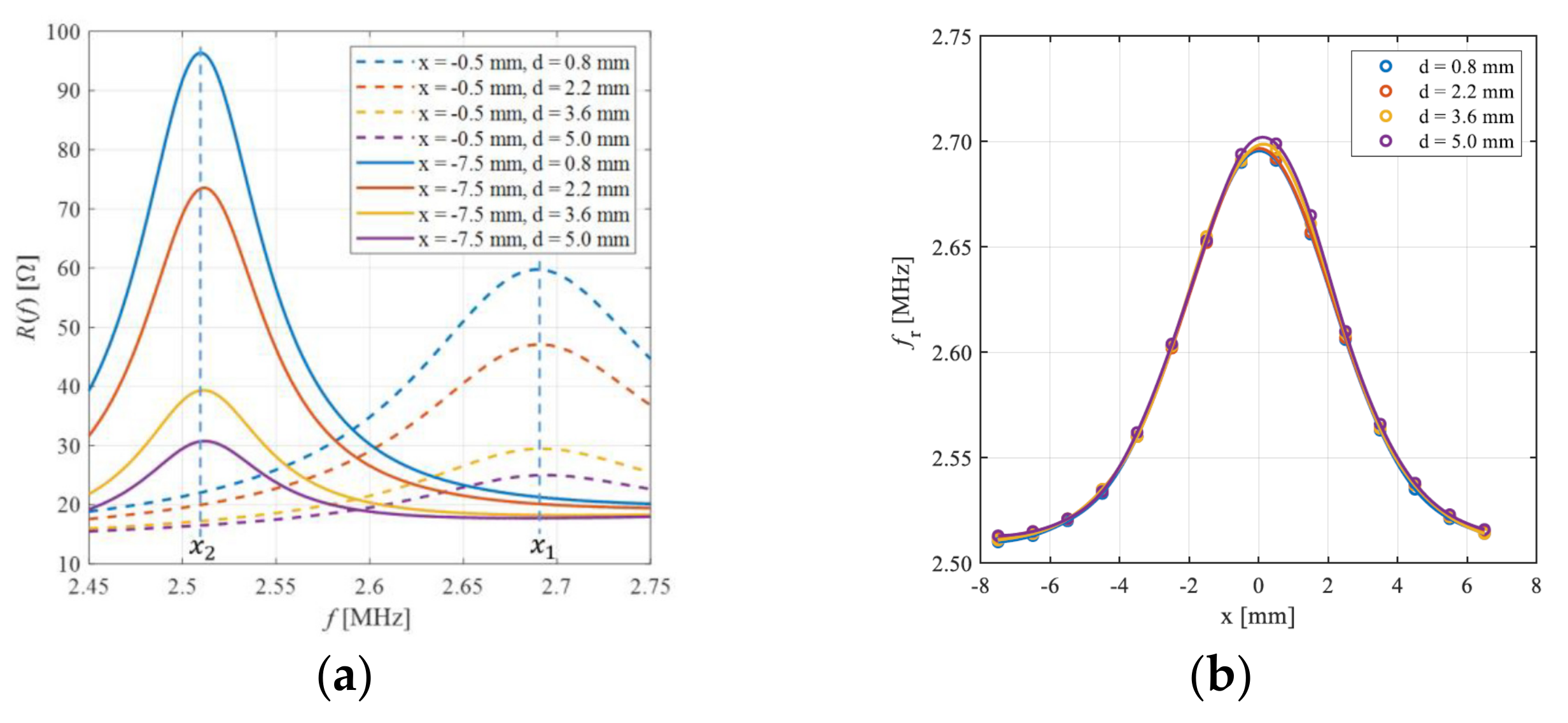
Without the sphere, fr0 = 2.51 MHz was measured. Figure 2a shows the R(f) for two selected sphere positions (x1 = −0.5 mm and x2 = −7.5 mm) while varying d, showing that d acts only as a scaling factor. Figure 2b shows fr as a function of x for different values of d. The sphere was detected up to |x| < 7.5 mm, while at x = 0, a maximum frequency variation of ∆fr = frfr0 = 180 kHz was measured in the explored range. The reported results show minimal residual dependences of fr on d, which can be eventually reduced by adopting established compensation techniques [3]. The results validate the possibility of the contactless interrogation of an IS for conductive target detection. Ongoing tests are exploring the ability to detect downscaled target sizes such as conductive particles in nonconductive fluids.

Author Contributions

Design and development of the device M.Z., A.N. and M.F.; experimental activity, M.Z., A.N. and M.F.: analysis of experimental data, M.Z. and M.F.; writing—original draft preparation, M.Z.; review and editing, M.Z., A.N., M.B., M.F. and V.F.; conceptualization and supervision, V.F. All authors have read and agreed to the published version of the manuscript.

Funding

This research received no external funding.

Institutional Review Board Statement

Not applicable.

Informed Consent Statement

Not applicable.

Data Availability Statement

Not applicable.

Conflicts of Interest

The authors declare no conflicts of interest.

References

  1. Liu, Z.; Wu, S.; Raihan, M.K.; Zhu, D.; Yu, K.; Wang, F.; Pan, X. The Optimization of Parallel Resonance Circuit for Wear Debris Detection by Adjusting Capacitance. Energies 2022, 15, 7318. [Google Scholar] [CrossRef]
  2. Wang, M.; Shi, H.; Zhang, H.; Huo, D.; Xie, Y.; Su, J. Improving the Detection Ability of Inductive Micro- Sensor for Non-Ferromagnetic Wear Debris. Micromachines 2020, 11, 1108. [Google Scholar] [CrossRef] [PubMed]
  3. Demori, M.; Baù, M.; Ferrari, M.; Ferrari, V. Electronic Technique and Circuit Topology for Accurate Distance-Independent Contactless Readout of Passive LC Sensors. AEU—Int. J. Electron. Commun. 2018, 92, 82–85. [Google Scholar] [CrossRef]
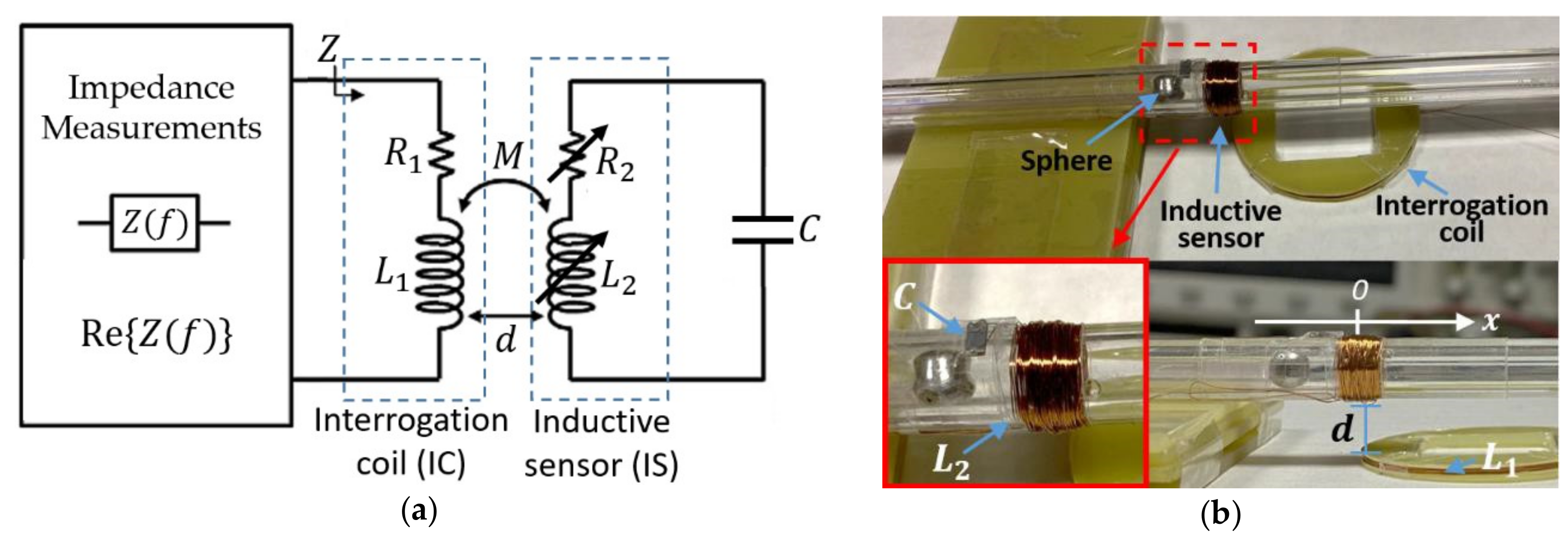
Figure 1. (a) Block diagram of the readout system based on impedance measurement. R1 = 15.2 Ω, L1 = 36.4 µH, R2 = 72 Ω, L2 = 144 µH without the sphere; (b) developed setup used to test the proposed IS for conductive particle detection.
Proceedings 97 00095 g001
Figure 2. (a) Measured R(f) with the conductive sphere placed at x1 = −0.5 mm and x2 = −7.5 mm for different values of d; (b) measured fr as a function of x for different values of d.
Proceedings 97 00095 g002
Disclaimer/Publisher’s Note: The statements, opinions and data contained in all publications are solely those of the individual author(s) and contributor(s) and not of MDPI and/or the editor(s). MDPI and/or the editor(s) disclaim responsibility for any injury to people or property resulting from any ideas, methods, instructions or products referred to in the content.