Proceeding Paper

Multi-Objective Optimization Design of a 30 kW Electro-Hydrostatic Actuator †

1
School of Mechanical Engineering and Automation, Beihang University, Beijing 100083, China
2
Innovative Hydraulics and Automation (IHA), Faulty of Engineering and Natural Sciences, Tampere University, 33720 Tampere, Finland
*
Author to whom correspondence should be addressed.
Presented at the First International Electronic Conference on Actuator Technology: Materials, Devices and Applications, 23–27 November 2020; Available online: https://iecat2020.sciforum.net/.
Proceedings 2020, 64(1), 5; https://doi.org/10.3390/IeCAT2020-08525
Published: 22 November 2020

Abstract

:
Electro-hydrostatic actuators (EHAs) combine the advantages of electric and hydraulic actuation, and it results in a preferable solution for heavy load actuation. The required power level of the EHA is increasing because it is being introduced to large vehicles such as submarines and heavy launch vehicles. Thus, a 30 kW EHA is under development for launch vehicles, which simultaneously require high dynamic performance, light weight, high efficiency, etc. Therefore, a dedicated multi-objective optimization design method is proposed for the preliminary design of the 30 kW EHA. In this study, firstly, the design requirements were analyzed for the launch vehicle application, and the objectives and the constraints of the optimization design were defined for the 30 kW EHA. Secondly, dedicated models were developed for evaluating each objective or constraint, including weight, bandwidth, and efficiency. Thirdly, the multi-objective EHA optimization design was implemented based on the genetic algorithm. Lastly, the optimization design results were evaluated through simulation analysis, which demonstrated that the 30 kW EHA achieved more than 10 Hz bandwidth with under 72 kg weight while the efficiency was also optimized.

1. Introduction

Heavy machinery and vehicles conventionally utilize hydraulic actuators due to the advantages of high power-to-weight ratio, high force capability, durability, etc. On the other hand, the conventional hydraulics characterized by low efficiency and difficulty to perform maintenance results in incompatibility with the modern industry. Therefore, the electro-hydrostatic actuators (EHAs), which combine the advantages of hydraulic and electric actuation, are becoming a preferable solution. However, the power level of current EHAs is usually under 15 kW, yet is enough to replace the conventional hydraulics utilized in the huge machinery and vehicles, such as heavy launch vehicles and submarines. This is because high power EHAs are more challenging to achieve the same level of dynamic performance and compactness of conventional hydraulics. One way to alleviate this gap is to improve the design method, which can allow better use of the current techniques and extend the abilities of EHAs, such as using optimization design.
Many researchers are working on developing a more powerful optimization design method for actuators, particularly the EHAs. However, the existing optimization design methods are mostly only used as a reference or for a partial design task, rather than used for developing the whole actuator. This is because the existing optimization design usually only involves particular requirements, which lacks credits for being adopted directly. Budinger et al. proposed a preliminary design method of electro-mechanical actuators considering requirements such as mass, output force and speed, vibratory environment, losses, and temperature [1], whereas the control performance wasn’t involved. Lei et al. put forward a robust optimization design method for electrical drive systems, which included both motor and controller performance [2]. However, the controller was optimized separately, which left the motor optimization without considering control performance. Roos’s design method for mechatronic servo systems also optimized the physical and control performance sequentially [3]. Andersson introduced a multi-objective optimization design method for hydraulic actuators, but it only considered the control error while not considering the response time [4]. Kim et al. and Golovanov et al. suggested an optimal design method for electrical machines that didn’t consider the control performance [5,6]. Xue et al. proposed a multi-objective optimization design method of EHA, whereas the control parameters were not analyzed clearly [7]. Optimization design excluding key requirements like the control performance results in incompetence for developing actuators for the huge heavy machinery and vehicles, which simultaneously possess multiple challenging requirements. Therefore, this paper proposes a multi-objective optimization design framework that involves the requirements directly from the EHA specifications, especially the control performance. Dedicated estimation models are needed to implement this method.
This paper is organized as follows: Section 2 analyzes the preliminary design task of the 30 kW EHA and transfers the design task into a multi-objective optimization problem. The dedicated models for evaluating the objectives and constraints are developed in Section 3. Section 4 implements the design and presents the design results. Section 5 verifies the design results using an AMESim model. The conclusion is drawn in Section 6.

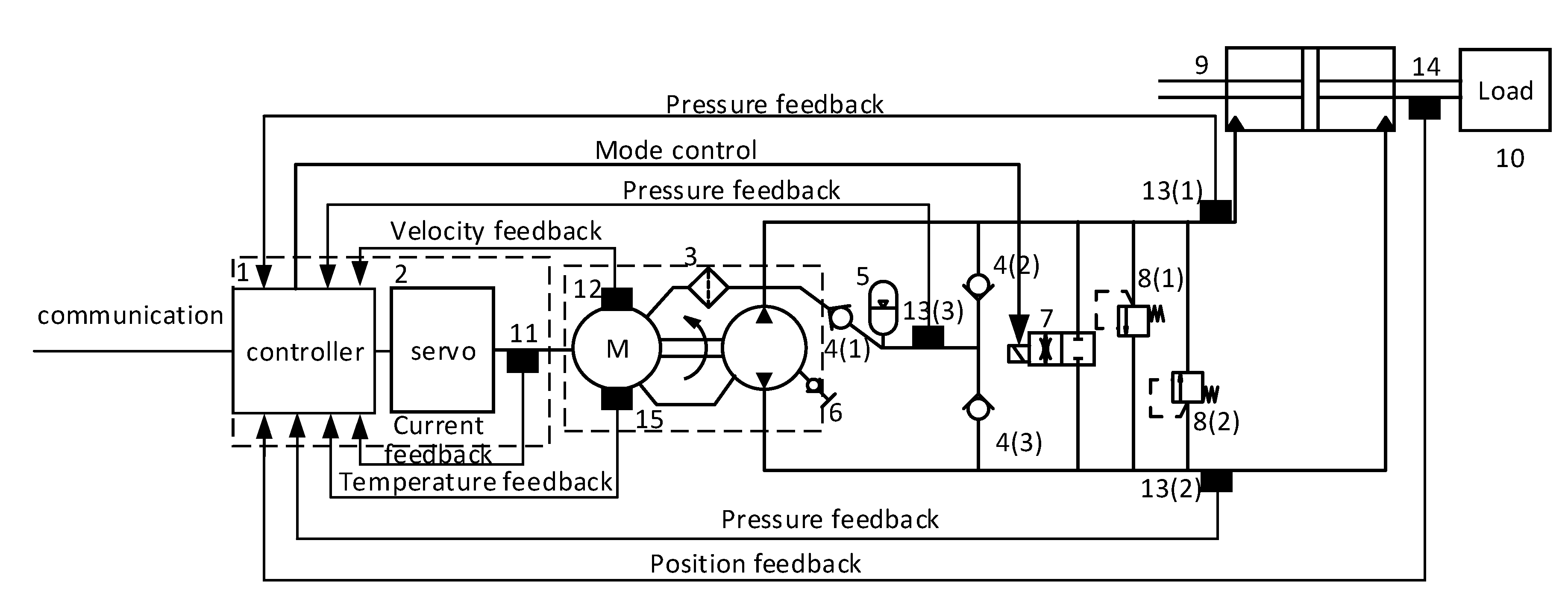
2. The Preliminary Design Task of the 30 kW EHA

The standard ISO 22072 suggests the general requirements for developing an aerospace EHA [8]. Multiple requirements, such as mechanical performance, control performance, safety, life, and working conditions, should be considered simultaneously, which results in the design phase being a critical step for EHA development. As for the heavy launch vehicle EHAs, high criteria are applied to several conflicting requirements, such as high power versus low weight, high dynamic versus low power consumption, etc. Therefore, careful trading off should be performed during the EHA sizing procedures. The major EHA requirements of the case study in this paper are in Table 1. It’s an actuator for the thrust vector control of a heavy launch vehicle. The power level is as high as 30 kW, whereas the mass is required to be lower than 115 kg. Furthermore, the bandwidth of the position control loop should reach 8 Hz, which is challenging even for lower power EHAs [9,10]. A preliminary design method based on multi-objective optimization is proposed to resolve these design challenges.
The multi-objective optimization can search for the optimum solutions that are subjected to conflicting objectives. The EHA preliminary design can be treated as a multi-objective optimization problem, where the bounded requirements are defined as constraints, the open requirements are defined as objectives, and the parameters to be determined are defined as variables. The schematics of the studied EHA are shown in Figure 1, which is the input of the preliminary design. The EHA preliminary design will determine the component types and major parameters, which are defined as the variables of the optimization. Since the bandwidth, the mass, and the efficiency are attributes that can strengthen the EHA competence, they are defined as the optimization objectives. The remaining requirements in Table 1, except for the ambient temperature, are defined as the constraints. The ambient temperature affects the thermal management design of the EHA, which is an extra step in addition to the optimization design. The thermal management devices are added when necessary, which is evaluated individually upon the optimization results.
As a result, the EHA preliminary design is transformed into the following optimization problem:
min   f ( x ) = [ f 1 ( x 1 , x 2 , , x n ) f 2 ( x 1 , x 2 , , x n ) f m ( x 1 , x 2 , , x n ) ] , Subject to x Ω , g ( x ) 0
where (x1, x2, …, xn) are the major parameters of the EHA, f(x) are the open requirements, g(x) are the bounded requirements, and Ω is the parameter space. The preliminary design utilized lumped parameters for sizing the EHA, which consist of the lumped parameters of the motor, the pump, the cylinder, etc. However, not all these parameters are used as the optimization variables since they are interrelated with each other due to the component design constraints. For example, the motor diameter and weight highly depend on its rated torque. Therefore, only the major parameters of those lumped parameters are used as the optimization variables. The remaining parameters will be derived by analytical or estimation tools during or after the optimization design [11]. The final values of these lumped parameters are the output of the preliminary design, which will be utilized as the specifications of the following detailed EHA design. The chosen major parameters (x1, x2, x3) in this paper are the motor rated torque Tm (Nm), the pump displacement Dp (mL/rev), and the piston diameter of the cylinder dpis (m), respectively.
The definition of the objectives and the constraints, together with the implementation of the optimization design, are explained in the following sections.

3. Evaluation Models for the Objectives and Constraints

Optimization design is an iterative process. Each iteration will evaluate the objectives and constraints for one or several times in order to decide how to proceed with the optimization process. The design requirements are transformed into the objectives and constraints of the optimization design. This section introduces the dedicated evaluation models for the objectives and constraints of the EHA optimization design. The evaluation models utilize the optimization variables as input and produce the corresponding values of the objectives and constraints.

3.1. Evaluation Model of the EHA Mass

The EHA mass is the sum of the component mass, as in Equation (2):
m EHA = m m + m p + m c + m b
where mEHA, mm, mp, mc, and mb are the mass of EHA, motor, pump, cylinder, and manifold (including the reservoir), respectively. The motor and the pump are customized by subcontractors and are usually applied to similar geometries and materials within the same series. Therefore, the scaling law can be used to derive the mass of a customized motor or pump from one reference component [11]. The major parameter of the customized component is employed as the dependent variable for this derivation. The mass estimation models for the motor and the pump are as shown in Equation (3), of which the coefficients are derived through regression analysis based on the previous components developed for similar applications:
m m = 0.1397 T m 1.308 + 2.051 , m p = 0.2717 D p 1.308 + 0.7186 .
The moment of inertia is the lumped parameter that needs to be determined during the EHA preliminary design. It can be estimated using the same method as the mass, as shown in Equation (4). The moment of inertia is also necessary for the following estimation model derivation.
J m = 0.0003666 T m 0.576 , J p = 0.0008218 T D p 0.2366 ,
where Jp and Jm are the moments of inertia of the pump and the motor, respectively. The cylinder is a typical symmetric single rod cylinder [12], of which the structure is concise. Its mass can be estimated through analytical calculation, as in Equation (5):
m c = m pis + m shell + m bottom , m pis = π 4 ( d pis + δ pis ) 2 ( s+ l pis + l top )ρ π 4 d pis 2 (s+ l pis )ρ+ π 4 d shell 2 l pis ρ m shell = π 4 ( d shell + δ shell ) 2 ( s+ l pis + l top )ρ π 4 d shell 2 ( s+ l pis )ρ m bottom =h π 4 ( d shell + δ shell ) 2 ρ
where mpis, mshell, and mbottom are the piston mass, shell mass, and bottom mass, respectively; dpis is the inner diameter of the rod; δpis is the wall thickness of the rod; s is the cylinder stroke; lpis is the length of the piston; ltop is the length of the rod head; dshell is the inner diameter of the cylinder; δshell is the wall thickness of the cylinder wall; ρ is the density of the cylinder material; and h is the length of the cylinder bottom. dpis is actively assigned during the optimization process. δpis, lpis, ltop, dshell, δshell, and h are derived by cylinder design formula, which can achieve enough accuracy thanks to the simple structure of the cylinder [13]. s is constrained by the EHA design requirements. Finally, the EHA mass can be estimated once the optimization variables (Tm, Dp, dpis) are assigned.

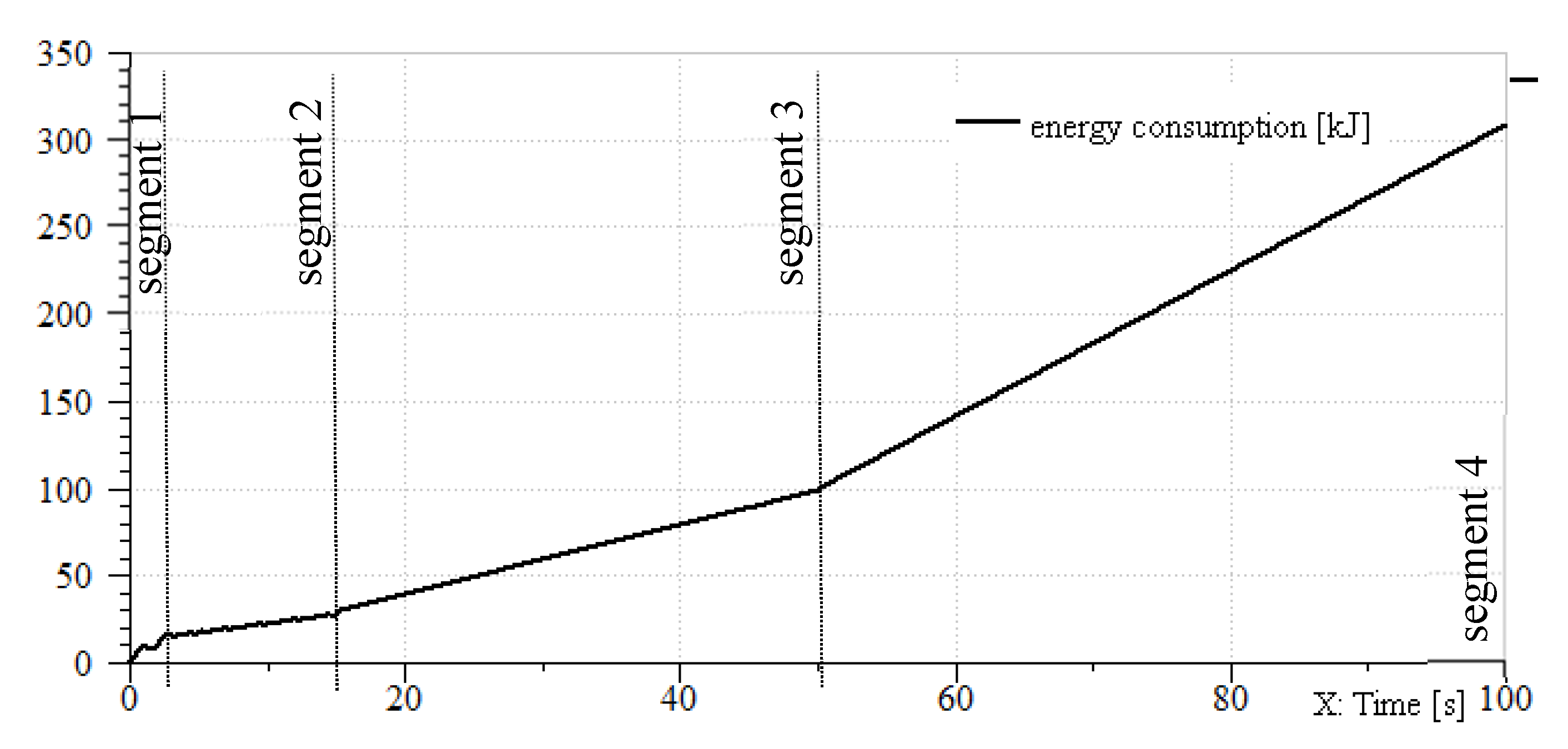
3.2. Evaluation Model of the EHA Efficiency

EHA is developed based on specified duty cycles. Therefore, improving EHA efficiency means decreasing the energy consumption under the specified duty cycles. A model that can estimate the EHA energy consumption can be used in the proposed optimization design framework. The function of the model is illustrated in Figure 2. It should calculate the electrical power-consumption of the EHA after the specified duty cycle is imported. A backward simulation method is chosen due to its advantages of low calculation cost and no need of a controller [14].
Firstly, the specified duty cycle is discretized with a fixed time step. Then, the cylinder output velocity v(k) and force F(k) of each time step k are defined as the average values within the time step. The corresponding pressure difference Δ P ( k ) and input flow Q cy ( k ) of each time step are calculated based on Equation (6),
Q cy (k)=Av(k)+ C c ΔP(k) ΔP(k)= F(k)+Bv(k) A
where A is the cylinder area, which can be derived based on the optimization variable dpis; the cylinder leakage coefficient Cc and the viscous friction coefficient B are generated by scaling law-based parameter estimation tools. The pump power input and the motor power input can be calculated sequentially using a similar method, as in Equation (7),
Q pump ( k ) = Q cy ( k ) + C p Δ P ( k ) ω ( k ) = Q pump D p T ( k ) = J d ω ( k ) d t + k fric ω ( k ) + Δ P ( k ) D p 2 π d w ( k ) d t = { ω ( k ) h ,   w h e n   k = 1 ω ( k ) ω ( k 1 ) h ,   w h e n   k > 1 I m ( k ) = T ( k ) K t U m ( k ) = L d I m ( k ) d t + K e w ( k ) + I m ( k ) R d I m ( k ) d t = { I m ( k ) h ,   w h e n   k = 1 I m ( k ) I m ( k 1 ) h ,   w h e n   k > 1
where Qpump is the input flow of the pump; ω is the rotation speed of the motor-pump; T is the driving torque of the pump; J is the sum of Jp and Jm, which are derived by Equation (4); the leakage coefficient of the pump Cp and the viscous friction coefficient kfric are derived by scaling law-based parameter estimation tools; I m is the input current of the motor winding; U m is the input voltage of the motor winding; the motor torque constant Kt, the motor inductance L, the motor winding resistance R, and the back electromotive force coefficient Ke are generated automatically; and h is the step size. Finally, the EHA power consuming is derived by Equation (8).
E = U m ( k ) I m ( k ) h

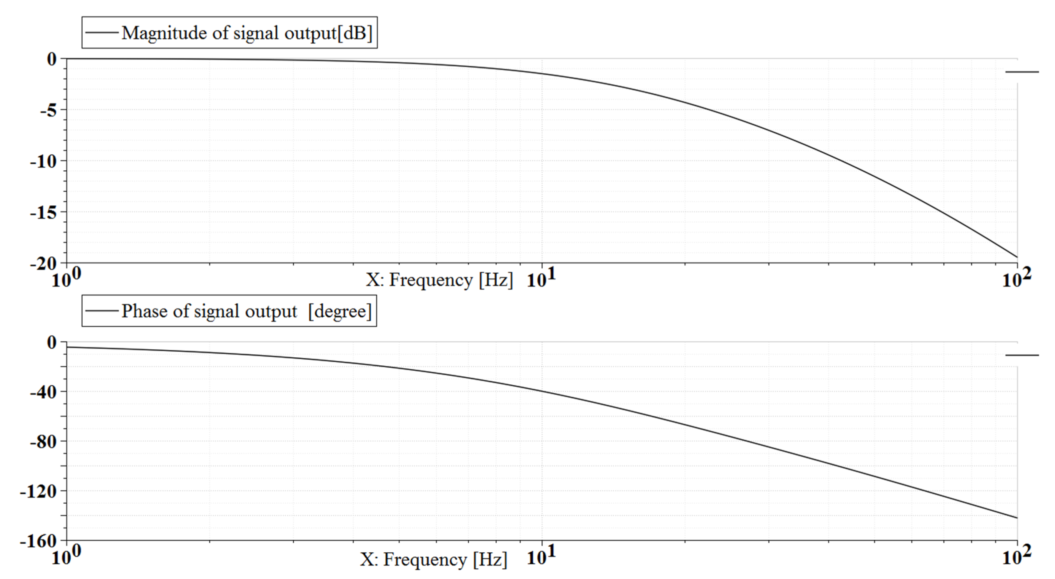
3.3. Evaluation Model of the EHA Bandwidth

With given parameters, the EHA bandwidth can be estimated based on cybernetics. A basic PID based cascade controller is selected for implementing the EHA control model. A more advanced control method is not recommended for the current occasion for several reasons. Firstly, the advanced controller usually requires accurate models, which are not easy to build during the preliminary design stage. Secondly, utilizing a more advanced controller in the preliminary design will overestimate the EHA control performance, which will increase the risk of failing to fulfill it in the following development stage. The bandwidth estimation method is explained in the following texts.
The open-loop transfer function of EHA is as in Equation (9) [15],
G 0 ( s ) = D p G pp ( s ) G cp ( s ) s 1 , G pp ( s ) = K t L J s 2 + ( K f L + R J ) s + R K f + K t K e , Gcp(s)=A1VmEA2s2+(CtmA2+VBEA2)s+CstBA2+1 ,
where the fluid volume V and the fluid bulk modulus E are generated automatically; C st is the sum of Cp and Cc; the load mass m is specified in the EHA design requirements. The cascade controller consisting of current loop control, velocity loop control, and position loop control is adopted, as shown in Figure 1. The controller is usually capable of achieving enough control performance of the current and speed loop resulting in that the open-loop EHA model is simplified into an integrator as in Equation (10) [16],
Gos(s)=GcxKos/s , K o s = A D p B C s t + A 2 ,
where the position loop controller Gcx can be implemented based on PI control method. So, the closed-loop position control of the EHA can be depicted as in Equation (11),
X(s)= K px K os s+ K os K ix s 2 + K px K os s+ K os K ix X d ( s ),
where Kpx and Kix are the proportional gain and integral gain, respectively. In order to achieve a second-order system with a damping ratio equaling to 1, Kpx and Kix should fulfill Equation (12),
K px =2 ω c / K os , K ix = ω c 2 / K os ,
and the transfer function of the EHA position control is:
X( s ) X d ( s ) = 2 ω c s+ ω c 2 s 2 +2 ω c s+ ω c 2 .
The position control bandwidth ω b can be calculated from Equation (13) once ω c is determined. Firstly, the power restriction should be considered when determining ω c , which results in Equation (14),
ω c > min ( π D p 30 A x m n N , 1 2 π T max D p A x m ( A 2 J + D p 2 m ) ) ,
where xm is the amplitude of the sine command of the EHA, this value is specified in EHA design requirements; the motor nominal speed nN and the maximum torque of the motor Tmax are generated automatically. Secondly, the biggest value of ω c that determined by Equation (14) should be verified according to the stability requirements. The verification method is substituting ω c into Equation (15) and checking the stability margin. Decrease the value of ω c until the stability requirement is met [16]. Finally, the bandwidth ω b is estimated after ω c is decided.
G 0 ( s ) = ( K px + K ix s ) D p G cp ( s ) s 1 .

3.4. Evaluation Models of the Constraints

The remaining requirements including force and velocity related requirements, the control accuracy, the static stiffness, and the stroke are transferred into the constraints of the optimization process. When entering one iteration, the motor rated torque Tm, the pump displacement Dp, and the piston diameter of the cylinder dpis are assigned by the optimization algorithm. Other concerning parameters in the preliminary design will be generated automatically. The EHA force and velocity related attributes as well as the static stiffness can be calculated by basic design formula [17]. The stroke is directly fixed with the value in the design requirements. The control accuracy can be calculated based on the transfer function in Equation (13) after ω c is decided.

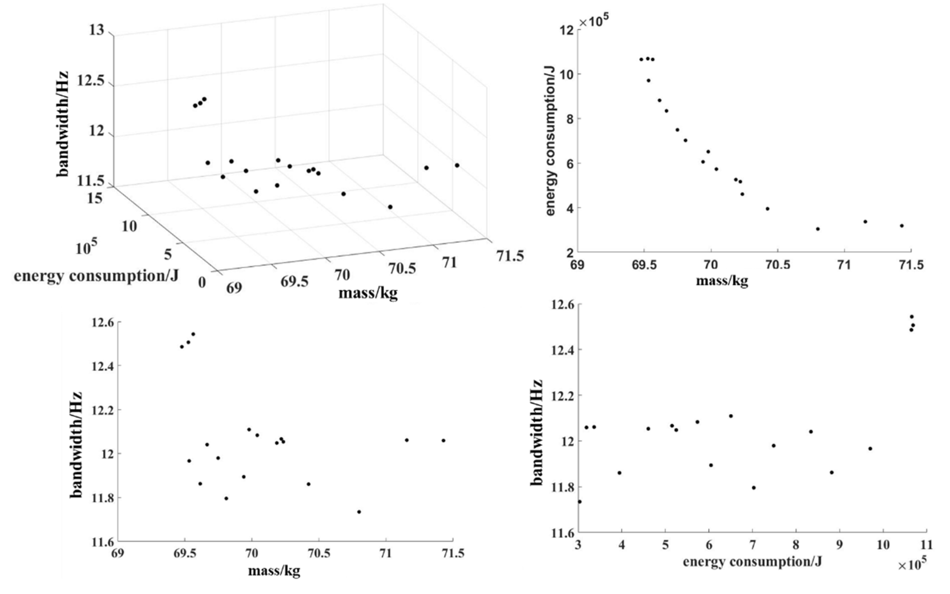
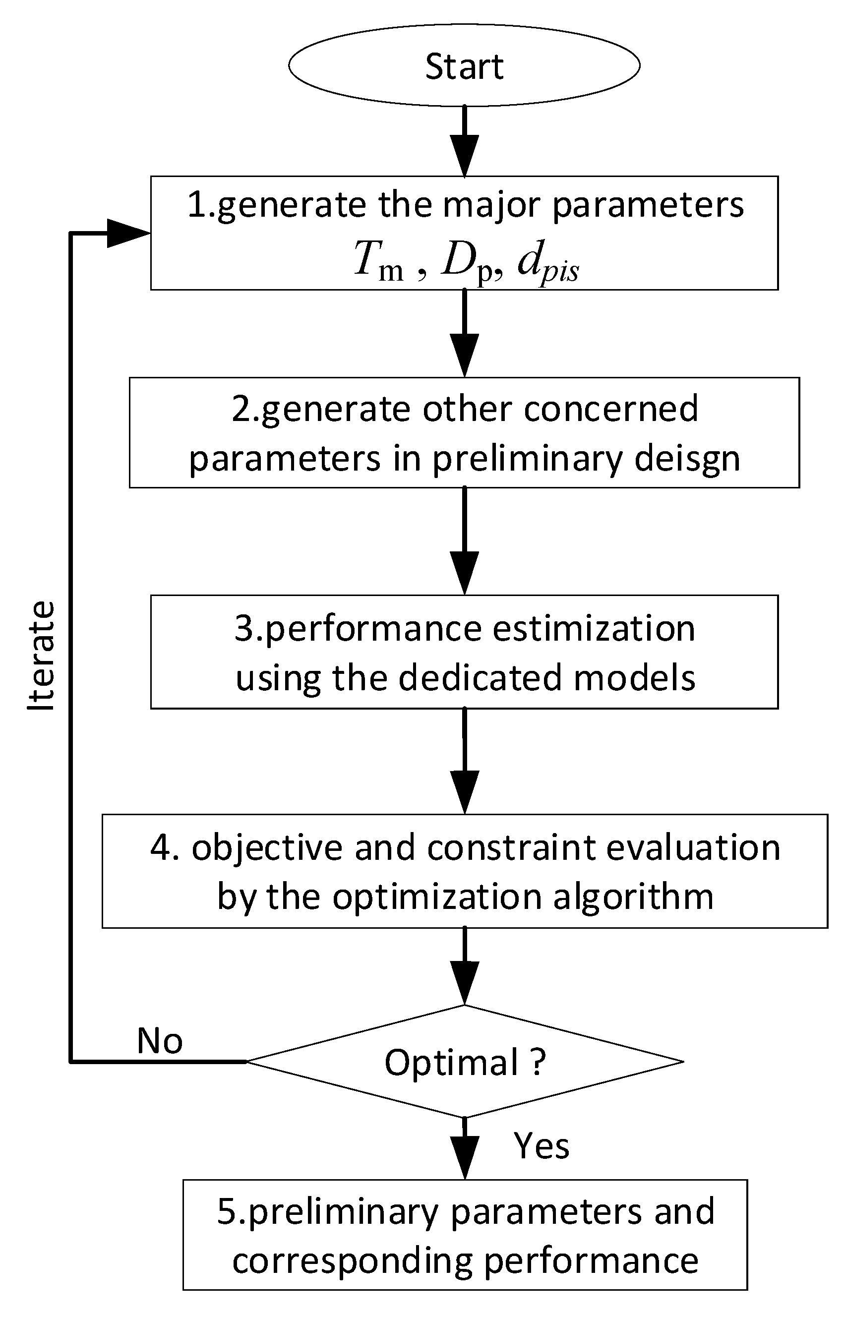
4. Optimization Design Implementation

The EHA preliminary design is transferred into a multi-objective optimization problem in Section 2 and Section 3. The design results can be obtained by solving this optimization problem using multi-objective optimization algorithms, which will return the Pareto front of the objectives. The genetic algorithm is selected in this paper. The preliminary design flow chart based on multi-objective design is shown in Figure 3.
The flow chart is implemented in Matlab software. Firstly, the three major parameters (Tm, Dp, dpis), which are defined as the optimization variables, are confined in intervals [20, 50], [5, 10], and [0.099, 0.12], respectively. The intervals are defined with margins of their rough valves, which are calculated based on the simple power conversion equations of each component [17]. Furthermore, the functions of generating parameters for step 2 and performance estimation for step 3 are pre-developed. Subsequently, the optimization starts to run and iterates the cycles until optimal results are obtained. Within each cycle, the optimization first generates the major parameters; then calls the parameter generation tools to obtain all the necessary parameters; next, feeds the parameters to the performance estimation models and gets the corresponding values of the objectives and constraints; and lastly, evaluates the objectives and constraints to decide to end the optimization or continue. The optimal performance and the corresponding parameters are the design results of the preliminary design. It is worth noting that the bandwidth is reciprocated for defining the objective in order to implement a minimum optimization.
During the optimization design, the maximum system pressure of the EHA is assumed as 28 MPa. The optimization results of the objectives are presented in Figure 4. The Pareto front shows the mass varying from 69 kg to 71.5 kg while the bandwidth varies from 11.6 Hz to12.6 Hz. The energy consuming (efficiency) conflicts with the mass and the bandwidth while the mass converges with the bandwidth. These results offer the designer an overall picture of the EHA design solutions and the envelope of the EHA performance. Each dot in the Pareto front represent a preliminary design option, which can be chosen upon the particular application.
Figure 5 illustrates the relationship between the optimization variables and the objectives. Smaller pumps contribute to higher bandwidth and lower mass while deteriorating the energy consuming. Smaller motors contribute to higher efficiency and lower mass while deteriorating the bandwidth. Smaller cylinders contribute to lower mass and higher efficiency while deteriorating the bandwidth. This is also effective information for the designer to achieve in-depth understanding of the EHA. Finally, (Tm = 21 Nm, Dp = 9.5 mL/rev, dpis = 100 mm) is selected for the particular application. The corresponding objectives are (mEHA = 71.155 kg, ω b = 12 Hz, E = 337 kJ).

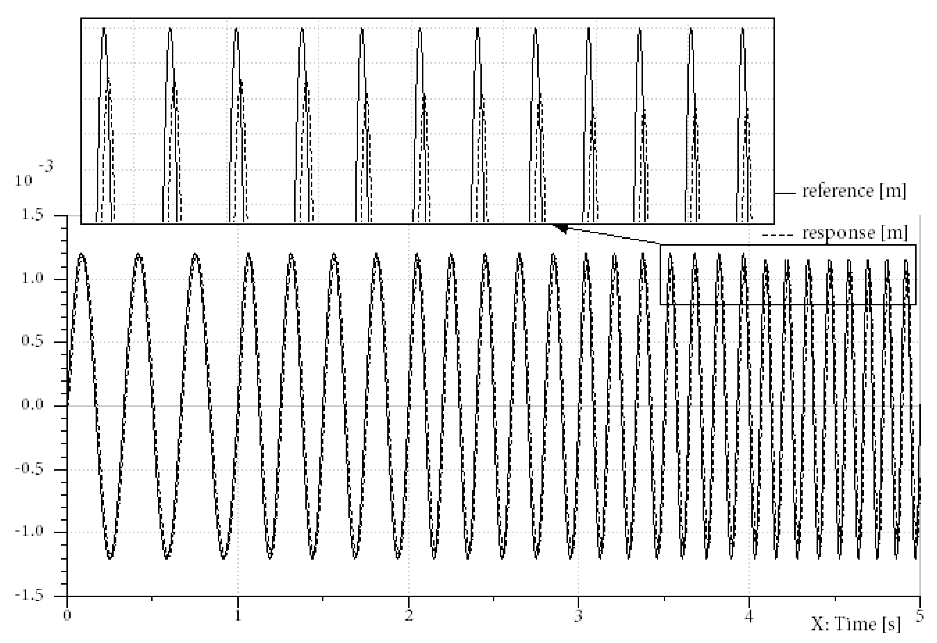
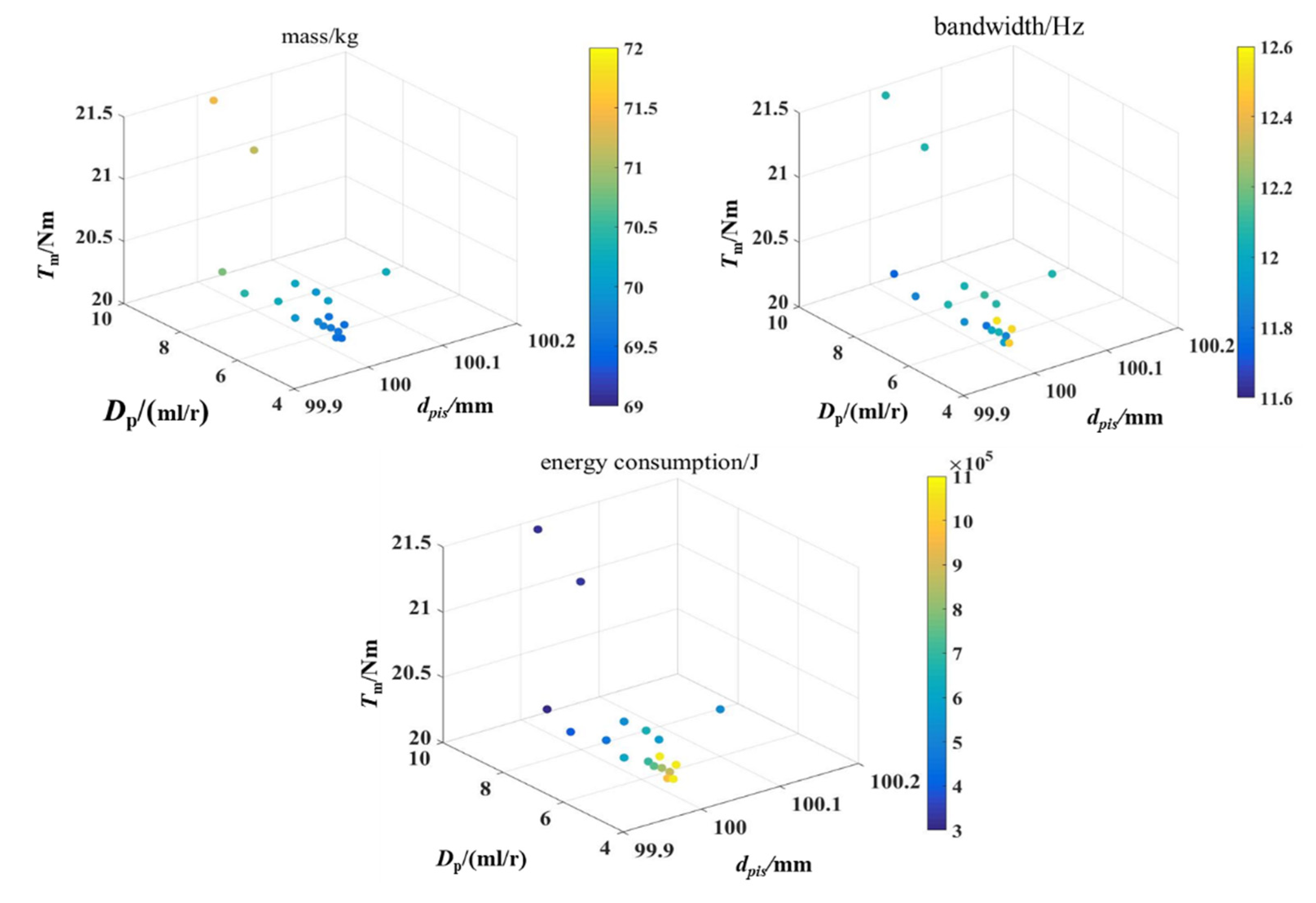
5. Simulation Analysis of the Design Solution

The optimization design adopts newly developed models for estimating different attributes. Therefore, the design quality depends on the accuracy of the estimation models. A classic multi-disciplinary EHA model developed in AMESim software was utilized to validate the optimization design results [7]. The parameters of the EHA AMESim model were assigned with the same values as the optimization design results. Then, the AMESim model was simulated under different conditions to test the performances that are defined as the objectives of the optimization design. The EHA model in AMESim also used a PID based cascade controller, which is similar to the one used in the optimization design.
Firstly, the AMESim model was fed with sweeping frequency command varying from 3 to 10 Hz, the EHA position response is presented in Figure 6. The output position follows the command well for all the range, which confirmed the fidelity of the bandwidth estimation models. The bode graph of the EHA was drawn in AMESim, as shown in Figure 7. It indicated a bandwidth of around 12 Hz for the EHA, which further verified the bandwidth estimation model.
Secondly, the AMESim model was simulated under the same duty cycle as for the energy consumption estimation in the optimization design (Section 3.2). The consumed energy is presented in Figure 8. The curve is divided into four segments, which is due to the duty cycle definition. The overall consumed energy is 308 kJ, which coincides with the estimation results in optimization design.
The simulation analysis proved that the models for the performance prediction in the optimization design achieved satisfying accuracy. Thus, the proposed optimization design method is competent to be used in the practical design task.

6. Conclusions

Heavy vehicles that put forward critical requirements for the actuation system, i.e., high efficiency, high dynamic, robustness, etc., should be simultaneously fulfilled under a high-power level. This results in a challenge for EHA development, which is a multidisciplinary and high integrated product. Particularly, the preliminary design should consider all the requirements and achieve design decisions with limited information. Therefore, in this research, multi-objective optimization is employed to tackle these issues.
In this paper, the EHA preliminary design task was analyzed and it was transferred into a multi-objective optimization problem. Parameter generation tools and dedicated models were proposed to implement the objective and constraint evaluation. The optimization design process was demonstrated for a 30 kW EHA. The design results were obtained and analyzed, where the 30 kW EHA finally achieved more than 10 Hz bandwidth with under 72 kg weight. The Pareto front illustrated the coupling effects among the objectives and outlined the EHA performance envelope. The optimization results also demonstrated how the design variables affect different objectives, which provide the designer an explicit instruction for sizing the EHA. Furthermore, the optimization results were verified with an EHA AMESim model, which additionally validate the proposed method. As a conclusion, the proposed method can be used as a practical tool for the high-power EHA development.

Author Contributions

C.Z. implemented the estimation models, parameter generating tools, the optimization design, and simulation analysis; X.H. proposed the method, coordinated this research, and wrote this paper; T.M. supervised this research and the writing; Y.F. organized this project and this paper. All authors have read and agreed to the published version of the manuscript.

Acknowledgments

The authors thank Beijing Institute of Automatic Control Equipment for funding this research and publishing this paper.

Conflicts of Interest

The authors declare no conflict of interest.

References

  1. Budinger, M.; Reysset, A.; Halabi, T.E.; Vasiliu, C.; Maré, J.C. Optimal preliminary design of electromechanical actuators. Proc. Inst. Mech. Eng. Part G J. Aerosp. Eng. 2014, 228, 1598–1616. [Google Scholar] [CrossRef]
  2. Lei, G.; Wang, T.; Zhu, J.; Guo, Y.; Wang, S. System-level design optimization method for electrical drive systems—Robust approach. IEEE Trans. Ind. Electron. 2015, 62, 4702–4713. [Google Scholar] [CrossRef]
  3. Roos, F. Towards a Methodology for Integrated Design of Mechatronic Servo Systems. Ph.D. Thesis, KTH, Stokholm, Sweden, 2007. [Google Scholar]
  4. Andersson, J. Multiobjective Optimization in Engineering Design: Applications to Fluid Power Systems. Ph.D. Thesis, Linköpings universitet, Linköping, Sweden, 2001. [Google Scholar]
  5. Kim, K.C.; Lee, J.; Kim, H.J.; Koo, D.H. Multiobjective optimal design for interior permanent magnet synchronous motor. IEEE Trans. Magn. 2009, 45, 1780–1783. [Google Scholar] [CrossRef]
  6. Golovanov, D.; Papini, L.; Gerada, D.; Xu, Z.; Gerada, C. Multidomain optimization of high-power-density PM electrical machines for system architecture selection. IEEE Trans. Ind. Electron. 2017, 65, 5302–5312. [Google Scholar] [CrossRef]
  7. Xue, L.; Wu, S.; Xu, Y.; Ma, D. A simulation-based multi-objective optimization design method for pump-driven electro-hydrostatic actuators. Processes 2019, 7, 274. [Google Scholar] [CrossRef]
  8. ISO 22072. Aerospace—Electrohydrostatic Actuator (EHA)—Characteristics to be Defined in Procurement Specifications; ISO: Geneva, Switzerland, 2011. [Google Scholar]
  9. Garrison, M.; Steffan, S. Two-fault tolerant electric actuation systems for space applications. In Proceedings of the 42nd AIAA/ASME/SAE/ASEE Joint Propulsion Conference & Exhibit, Sacramento, CA, USA, 9–12 July 2006; AIAA: Reston, VA, USA, 2006. [Google Scholar]
  10. Navarro, R. Performance of an Electro-Hydrostatic Actuator on the F-18 Systems Research Aircraft; NASA Technical Report 1997, NASA/TM-97-206224; NASA: Washington, DC, USA, 1997. [Google Scholar]
  11. Liscouët, J.; Budinger, M.; Maré, J.C.; Orieux, S. Modelling approach for the simulation-based preliminary design of power transmissions. Mech. Mach. Theory 2011, 46, 276–289. [Google Scholar] [CrossRef]
  12. Wei, S.; Honglei, H.; Yang, L.; Dijia, Z.; Jihai, J. Work characteristic analysis of single-rod symmetric cylinders. High Technol. Lett. 2017, 23, 286–292. [Google Scholar] [CrossRef]
  13. Yeaple, F. Hydraulic and electrohydraulic cylinders and actuators. In Fluid Power Design Handbook; CRC Press: Boca Raton, FL, USA, 1995; pp. 111–137. [Google Scholar]
  14. Ritari, A.; Vepsäläinen, J.; Kivekäs, K.; Tammi, K.; Laitinen, H. Energy Consumption and Lifecycle Cost Analysis of Electric City Buses with Multispeed Gearboxes. Energies 2020, 13, 2117. [Google Scholar] [CrossRef]
  15. Habibi, S.; Goldenberg, A. Design of a new high-performance electrohydraulic actuator. IEEE/ASME Trans. Mechatron. 2000, 5, 158–164. [Google Scholar] [CrossRef]
  16. Yang, R. Research on Control Strategy for Electro-hydrostatic Actuation System Based on a Novel Integrated Electrohydraulic Pump. Ph.D. Thesis, Beihang University, Beijing, China, 2019. [Google Scholar]
  17. McCullough, K. Design and characterization of a dual electro-hydrostatic actuator. Master’s Thesis, McMaster University, Hamilton, ON, Canada, 2011. [Google Scholar]
Figure 1. The schematics of the studied EHA: (1) Controller, (2) motor driver, (3) motor-pump unit, (4) check valves, (5) reservoir, (6) filling port, (7) solenoid valve, (8) relief valves, (9) cylinder, (10) load, (11) current sensor, (12) rotational speed sensor, (13) pressure sensors, (14) position sensor, (15) temperature sensor.
Proceedings 64 00005 g001
Figure 2. The function of the EHA energy consuming model.
Proceedings 64 00005 g002
Figure 3. The flow chart of the preliminary design.
Proceedings 64 00005 g003
Figure 4. Optimization results of the objectives.
Proceedings 64 00005 g004
Figure 5. Relationship between the optimization variables and the objectives.
Proceedings 64 00005 g005
Figure 6. Position response of the EHA AMESim model.
Proceedings 64 00005 g006
Figure 7. The bode graph of the EHA.
Proceedings 64 00005 g007
Figure 8. The energy consumption of the EHA.
Proceedings 64 00005 g008
Table 1. Major requirements of the electro-hydrostatic actuator (EHA) for a heavy launch vehicle.
DescriptionValueUnit
Maximum output force200kN
Rated output force100kN
Maximum output velocity150mm/s
Rated output velocity100mm/s
Stroke±55mm
Bandwidth of the position control loop8Hz
Control accuracy±0.1mm
Maximum mass115kg
Static stiffness9 × 107N/m
Ambient temperature−40~80
Publisher’s Note: MDPI stays neutral with regard to jurisdictional claims in published maps and institutional affiliations.

