Proceeding Paper

Development of Control Circuit for Inductive Levitation Micro-Actuators †

1
Institute of Microstructure Technology—Karlsruhe Institute of Technology, Hermann-von-Helmholtz-Platz 1, 76344 Eggenstein-Leopoldshafen, Germany
2
Institute of Robotics and Computer Vision, Innopolis University, 1 Universitetskaya Street, 420500 Innopolis City, Russia
*
Author to whom correspondence should be addressed.
Presented at the First International Electronic Conference on Actuator Technology: Materials, Devices and Applications, 23–27 November 2020; Available online: https://iecat2020.sciforum.net/.
These authors contributed equally to this work.
Proceedings 2020, 64(1), 39; https://doi.org/10.3390/IeCAT2020-08479
Published: 20 November 2020

Abstract

:
A control circuit for inductive levitation micro-actuators was developed in this research, the circuit’s performance and its electrical parameters are discussed. The developed control circuit was fabricated on a four-layer printed circuit board (PCB) board with a size of 60 × 60 ×25 m m . It consisted of a generator based on high-speed Flip-Flop components and a current amplifier build on a H-bridge configuration. The circuit was able to generate an AC current with a squared waveform in a frequency range from 8 to 43 MHz and with a peak-to-peak amplitude of up to 420 m A . To demonstrate the efficiency of developed circuit and its compatibility with a micro-actuation system, an inductive levitation micro-actuator was fabricated by using 3D micro-coil technology. The device was composed of two solenoidal coil designs, a levitation and a stabilization coil, with outer diameters of 2 and 3.8 m m , respectively. A 25 m diameter gold wire was used to fabricate the coils, with the levitation coil having 20 turns and the stabilization coil having 12 turns, similar to the micro-structure presented previously by our group. Using the developed control circuit, the micro-actuator was successfully excited and it demonstrated the actuation of aluminum disc-shaped micro-objects with diameters of 2.8 and 3.2 m m and, for the first time, an aluminum square-shaped object with a side length of 2.8 mm at a frequency of 10 MHz. To characterize the actuation, the levitation height and the current amplitude were measured. In particular, we demonstrated that the square-shaped micro-object could be lifted up to a height of 84 m with a current of 160 m A . The characterization was supported by a simulation using a 3D model based on the quasi-finite element model (FEM) approach.

1. Introduction

Electromagnetic levitation micro-actuators employ remote ponderomotive forces in order to act on a target environment or simply compensate for the force of gravity to hold a micro-object stably at equilibrium without mechanical attachment; these devices have already found wide applications and demonstrated potential as a new generation of micro-sensors and actuators with increased operational capabilities and the ability to overcome the domination of friction over inertial forces at a micro-scale.
There are number of techniques that allow the implementation of electromagnetic levitation into a micro-actuator system, and these can be classified according to the materials used and the sources of the force fields into two major branches: Electric levitation micro-actuators (ELMAs) and magnetic levitation micro-actuators (MLMAs). In particular, ELMAs have been successfully used as linear transporters [1] and in micro-inertial sensors [2,3]. MLAMs can be further split into inductive (ILMAs), diamagnetic (DLMAs), and superconducting micro-actuators and hybrid levitation micro-actuators (HLMAs) [4], which have found applications in micro-bearings [5,6,7], micro-mirrors [8,9], micro-gyroscopes [10,11], micro-accelerometers [12], bistable switches [13], nano-force sensor [14], micro-transporters [15], micro-accelerators [16], micro-motors [17,18,19], and resonators [20].
A wide spectrum of physical principles have been utilized and successfully implemented by using different techniques for micro-fabrication. However, recently developed 3D micro-coil technology [21] together with the integration of a polymer magnetic composite material for flux concentration allows the use of inductive levitation micro-actuator systems, firstly, as systems with an established micro-fabrication process in comparison to the other levitation actuator systems, and secondly, as high-performance systems. As a result of this progress, our work demonstrated the use of an inductive levitation actuator system with the lowest recorded current consumption [7], at around tens of mA. This avoids the usage of standard and bulky high-frequency current amplifiers for exciting the ILMA, replacing them with an integrated control circuit including the signal generator and amplifier and with a size comparable to the size of the micro-actuator system.
This prompted us to develop a control circuit on a four-layer printed circuit board (PCB) board with a size of 60 × 60 × 25 mm. It consisted of a generator based on a high-speed Flip-Flop and a current amplifier built on a bridge configuration. The circuit was able to generate an alternating current with a squared waveform in the frequency range of 8 to 43 MHz and with a peak-to-peak amplitude of up to 420 mA.
To demonstrate the efficiency of the developed circuit, we show its successful application for the excitation of an inductive levitation micro-actuator, which was fabricated using 3D micro-coil technology. The device was composed of two solenoidal coil designs, including levitation and stabilization coils of 2 mm and 3.8 mm in diameter, respectively. The levitation coil featured 20 turns of a gold wire and was 25 μ m in diameter, while the stabilization coil featured 12 turns, similar to the micro-structure presented previously by our group.
The micro-actuator was successfully excited by the control circuit, and it demonstrated the levitation of aluminum disc-shaped micro-objects with diameters of 2.8 and 3.2 mm and, for the first time, an aluminum square-shaped object with a side length of 2.8 mm at a frequency of 10 MHz. To characterize the actuation, the levitation height and the current amplitude were measured. In particular, we showed that the square-shaped micro-object could be lifted up to a height of 84 μ m with an rms current of 160 mA. The characterization was supported by the simulation using a 3D model based on the quasi-finite element model (FEM) approach. In particular, the simulation showed that the coil design produced the maximum levitation force to levitate the presented square-shaped proof mass (PM).

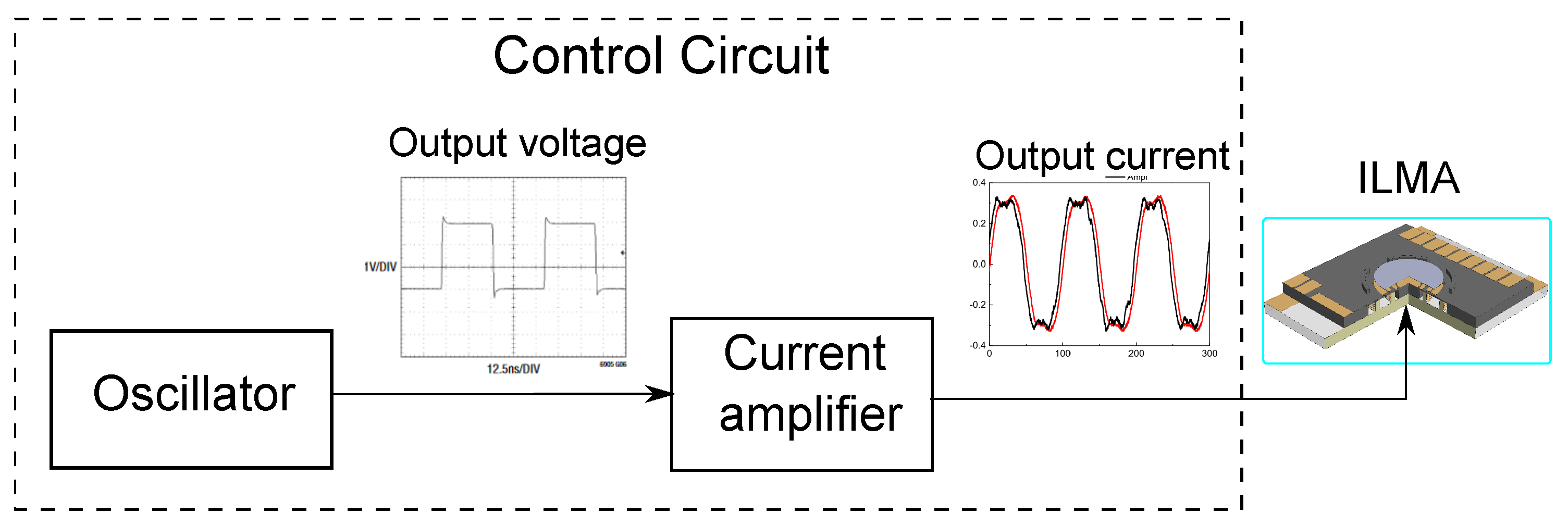
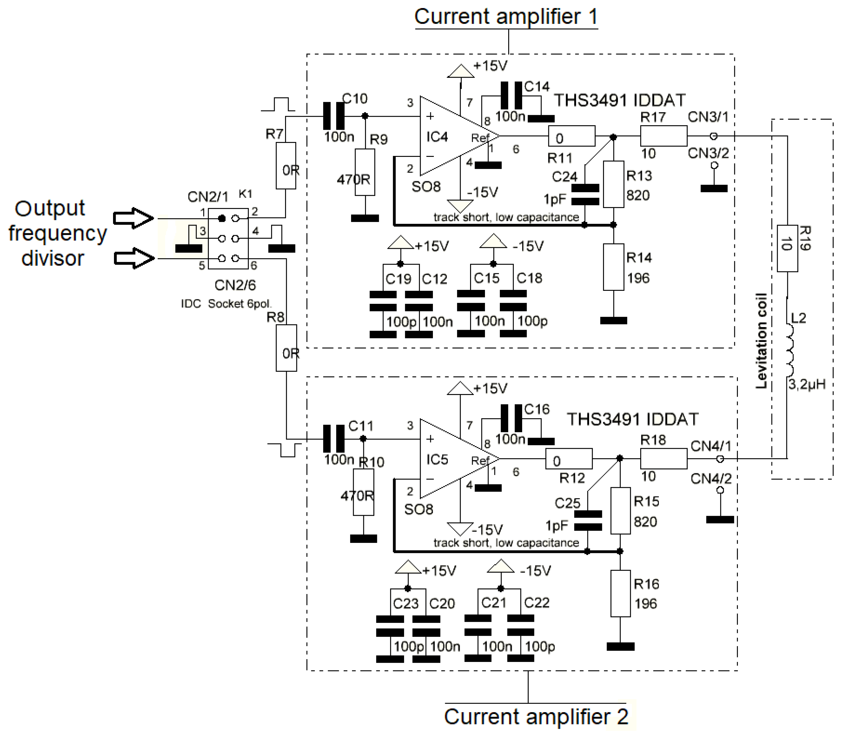
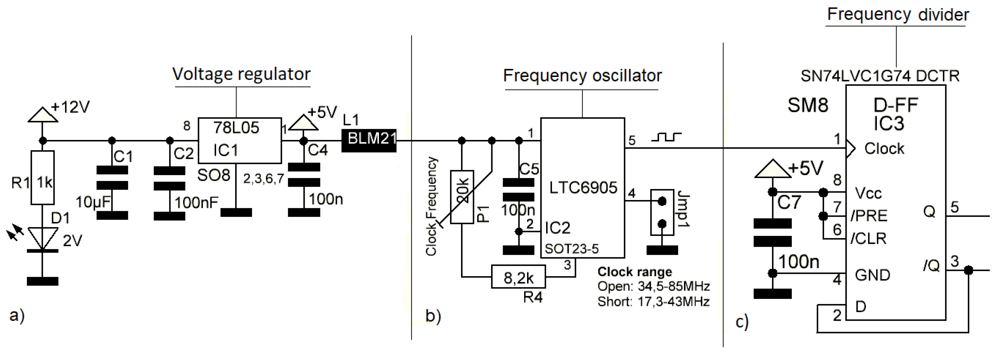
2. Development of Control Circuit

According to the results of the comprehensive characterization of the performance of the ILMA in our previous paper [22], where levitation height was considered as a function of the input parameters, i.e., the amplitude and frequency of the excitation currents, as well as the theoretical model to estimate the current versus frequency dependence for a given constant height of a disc-shaped proof mass, we showed that the main advantage of using 3D microcoils in the ILMA was related to the possibility of increasing the ampere-turn value as a result of the increased number of windings. This increased number of windings could be achieved in a single processing step, as opposed to, for example, planar coils. As a consequence, the current amplitudes required to achieve similar levitation performance could be reduced dramatically compared to the 2D case. However, we have also emphasized the precautions that must be taken when using 3D coil structures. These are related mainly to the range of operating frequencies, which are significantly reduced to a much smaller value for the self-resonant frequency of these 3D structures compared to their 2D counterparts.
Due to the previously discussed reasons and the results of measurements conducted in [22], the application of 3D microcoils in ILMAs requires a power supply that provides an excitation current with variation in the frequency range, amplitude, and waveform. The boundary conditions of these parameters are summarized below:
  • High frequency output voltage suppler from 0 to 40 Vpp;
  • High frequency current (maximum peak to peak) from 0 to 400 mA;
  • Rectangular waveform of the current;
  • Frequency operation range from 8.4 to 40 MHz.
This list of electrical parameters was applied as the requirements for the development of the control circuit. The control circuit consists of two main functional elements as shown in Figure 1, which are a generator (oscillator) and a current amplifier. The generator is responsible for shaping the current waveform with corresponding frequency range and proving the input signal for the current amplifier. Afterwards, the current amplifier delivers shaped AC current with the required electrical parameters to a ILMAs device for its excitation. Hence, the development process of the control circuit can be split into two main parts, namely, the development of an oscillator and a current amplifier. Both functional elements were integrated in one control circuit as shown in Figure 1.
The required peak to peak value of the AC current up to 400 m A provides a relative high value, and the necessity of a high frequency bandwidth with also a high impedance value generated by the levitation coil was the motivation for choosing the H-bridge configuration to build the configuration of the current amplifier. The H-bridge configuration avoids the usage of a coil transformer which has disadvantages of bandwidth limitation and high input current consumption. The current amplifier was embedded with an active cooling system to avoid overheating of the electronic components. To realize the proposed configuration fulfilling power and frequency output parameters, two high-power output current feedback amplifiers (THS3491) developed by Texas Instruments (Austin, TX, USA) were used. Figure 2 depicts the electrical circuit design of the current amplifier. An H-bridge configuration was built by using two chips (THS3491), which were supported by double voltage suppliers of ± 15   V . The input voltage for current amplifiers is controlled by the frequency divider flip-flop (please see Figure LM805+LTC6905+DFFIC3c), which helps to provide the symmetrical signals between the oscillator output and the amplifiers output. In this design, the output frequency given by the frequency oscillator is reduced by a factor of two.
Consequently, the oscillator must provide a frequency range of more than 80 M Hz . In order to meet this requirement, the oscillator was built using the LTC6905 chip, which is easy to employ and occupies very little board space. It requires only a single resistor to set the output frequency up to 170 M Hz with a typical frequency error of 0.5% or less. The designed circuit of the oscillator is shown in Figure 3. It is supplied by a single voltage supplier of 5 V . Voltage regulator (chip LM7805) helps to provide the required supplying voltage. The change in the range of oscillation frequency is performed by a jumper. When the jumper is closed the range of frequency is 7.6 to 26 M Hz and when it is opened, the range of frequency is 15 to 50 M Hz . The jumper connector is located in the frequency oscillator circuit (Jmp1) as presented in Figure 3b.
Finally, the proposed circuit design was fabricated in a four-layer PCB board with dimensions of 60 × 60 × 25 m m . Figure 4 presents the top view of the PCB with the location of the voltage regulator (LM7805), the frequency oscillator (LTC6905), divider (SN74LVC1G74), and the two amplifiers (THS3491). The cooling system, which is located behind of the PCB board, is not visible on the figure.

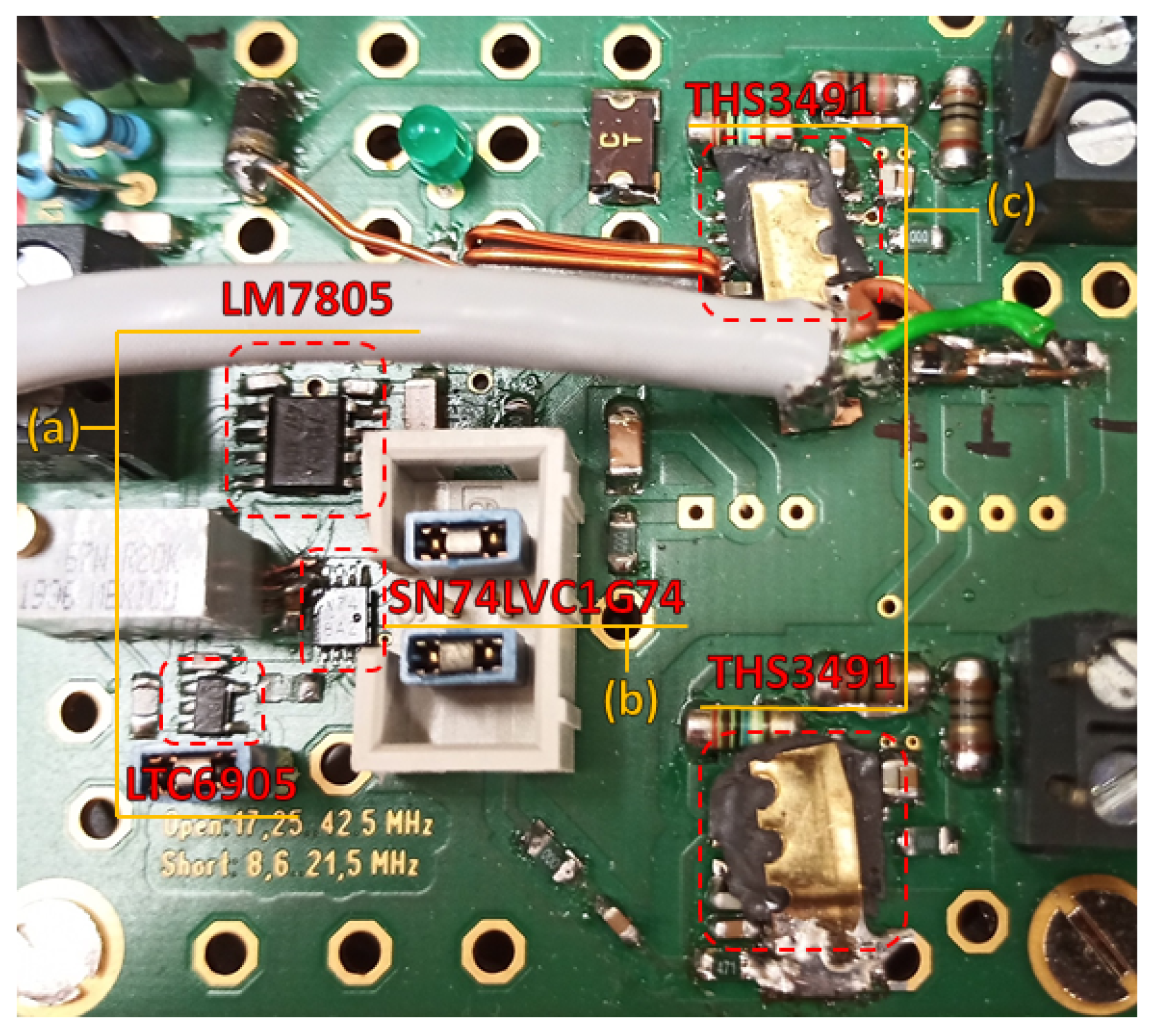
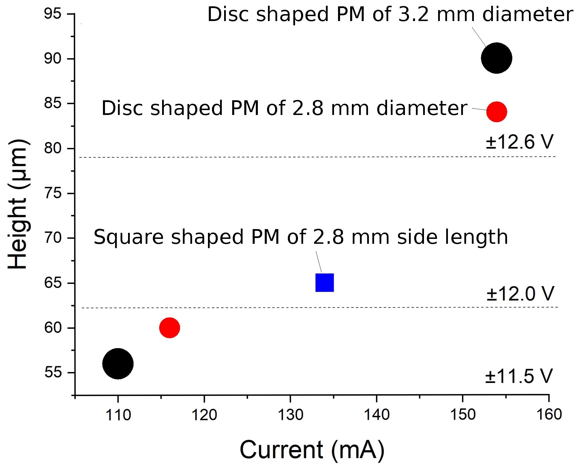
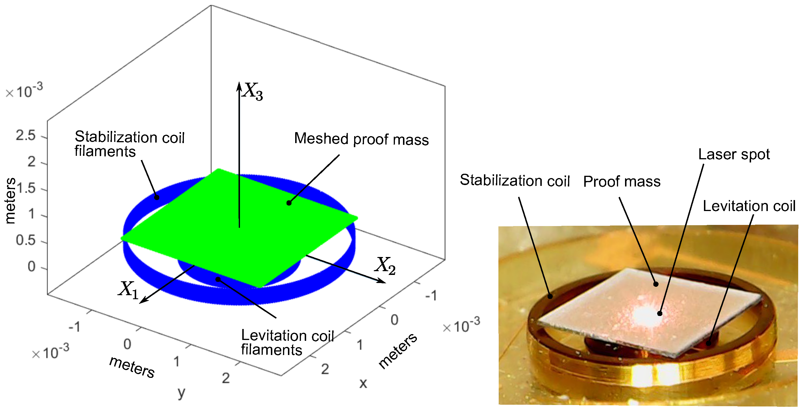
2.1. Experimental Setup

In order to verify the developed control circuit and demonstrate its application to ILMA, an experimental setup was designed as presented in Figure 5. The fabricated device of ILMA was mounted on the PCB board and fixed on the optical table. The levitation system was composed of two solenoidal coil designs including levitation and stabilization coils, 2 mm and 3.8 mm in diameters, respectively. The levitation coil has 20 turns of a gold wire with a 25 μ m diameter, while the stabilization one has 12 turns, this design is similar to the micro-structure presented previously by our group [6]. To control the levitation height of the PM in the vertical direction, a laser sensor (LK-G32) was built in the experimental setup. It was mounted on the the optical table, above of the PM. Afterwards, the PCB with the developed control circuit was connected to the device as shown in Figure 5, where the location of the cooling system under the PCB board is also presented.
A set of proof masses was produced to evaluate the levitation setup. Disc and square shapes were fabricated using an aluminium foil with a thickness ranging from 10 μ m –15 μ m .
With the integration of the levitation experimental setup and the developed control circuit was possible to successfully levitate the disc shaped PM of diameters of 2.8   m m and 3.2   m m and, for the first time, a square shaped PM with a side length of 2.8   m m at an excitation AC frequency of 10 M Hz . In particular, Figure 5 depicts the levitation of the disc shaped PM with a diameter of 3.2   m m at a height of 90 μ m . The results of the levitation heights measurements, type of PM, coil current, and the applied voltage were evaluated and presented in Figure 6.

3. Simulation

The mechanism of stabilization for the levitation, using a square shape PM, with the framework of a two coil design is similar to one as described in our previous work [23]. The induced eddy currents are distributed along with the levitated proof mass in a way that two circuits having maximum values of eddy current density can be identified. This effect was also demonstrated by performing the simulation based on a quasi-FEM model. The first circuit is corresponded to the eddy current distributed along with the edge of square-shaped PM and the second circuit is defined by the levitation coil. The later one has a circular path with a radius equal to the radius of the levitation coil. This mechanism can be split into two force interactions. The force interaction happens between the current in the stabilization coil and induced eddy current corresponding to the first circuit, which contributes mainly to the lateral stability of the levitated PM. While, the force interaction between the current in the levitation coil and induced eddy current corresponding the second circuit contributes mainly to the vertical and angular stability of the levitated PM.
The simulation is aimed to study the levitation force and to demonstrate that the current coil design produces the maximum levitation force, retaining the same value of the current in the coils. In this case, the simulation was conducted using the square shaped PM with a side length of 2.8 mm, and the method based on a quasi-FEM approach was applied [24,25].

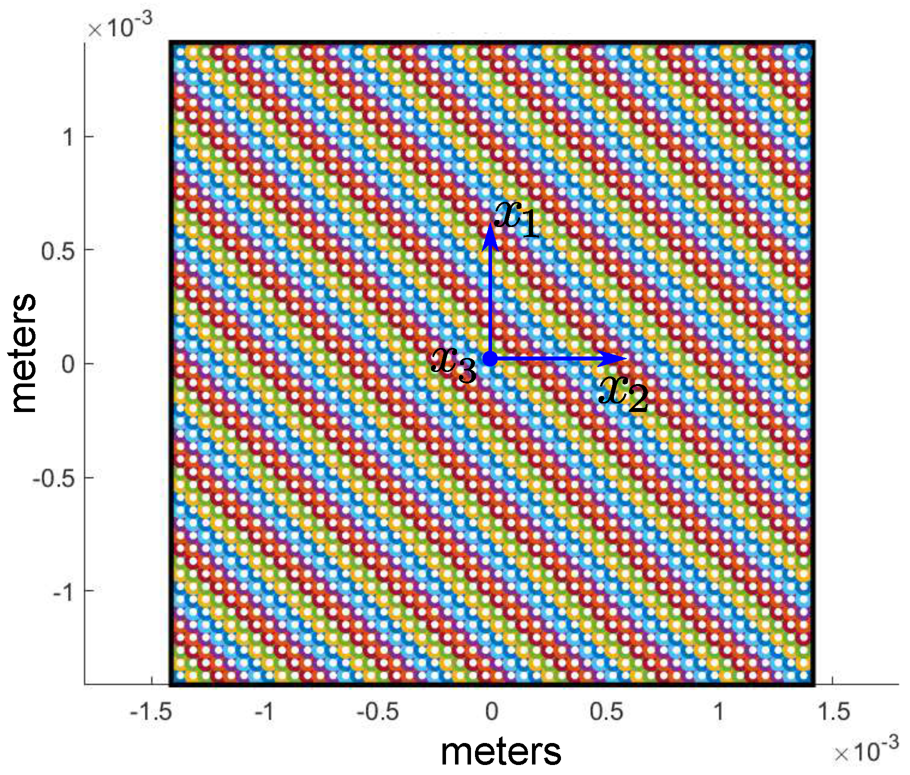
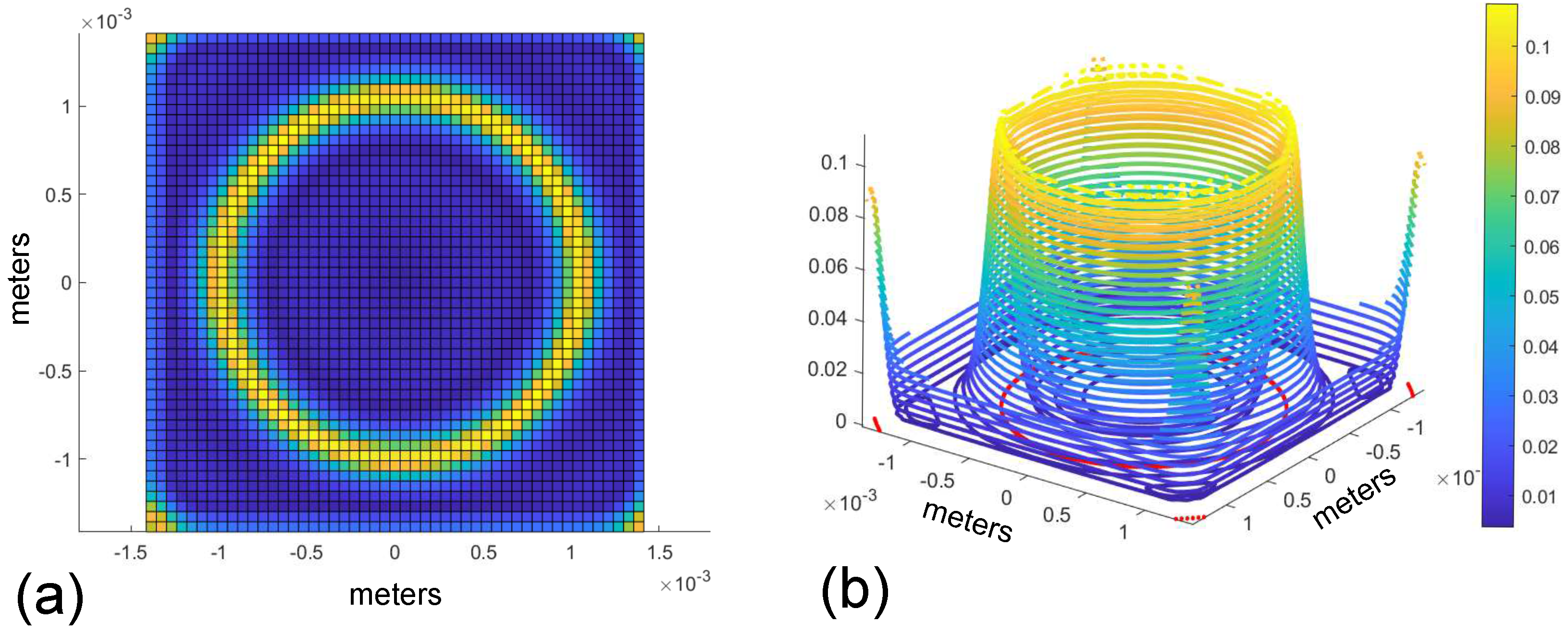
3.1. Simulation of Induced Eddy Current within the Proof Mass

At the beginning, the levitated PM area was meshed by circular elements of the same radius, R e =   2.8025× 10 3   m , as shown in Figure 7, a value of which was defined by a number of elements, n = 2500 . The 3D geometry of the two micro-coils was approximated by a series of circular filaments. The levitation coil was replaced by 20 circular filaments with a diameter of 2.0   m m , while the stabilization coil was replaced by 12 circular filaments with a diameter of 3.9   m m , which resulted in a total number N of 32 circular filaments. Assigning the origin of the fixed frame { X k } ( k = 1 , 2 , 3 ) to the centre of the circular filament, which corresponds to the first top winding of the levitation coil, the linear position of the circular filaments of levitation coil were defined as ( j ) r c = [ 0 0 ( j 1 ) · p ] T , ( j = 1 , , 20 ) , where p is the pitch equaling to 25 μ m . The same approach is applicable for the stabilization coil, ( j ) r c = [ 0 0 ( j 21 ) · p ] T , with the difference that the index j is varied from 21 to 32. For both coils, the Brayn angle of each circular filament is defined by ( j ) ϕ ̲ c = [ 0 0 0 ] T , ( j = 1 , , 32 ) .
The result of the mesh becomes a list of elements { ( s ) C ̲ = [ ( s ) ρ ( s ) ϕ ] T } ( s = 1 , , n ) containing information about the radius vector and an angular orientation for each element with respect to the coordinate frame { x k } ( k = 1 , 2 , 3 ). Afterward, the resulted matrix L ̲ was calculated as follows:
L ̲ = L 0 E ̲ + M ̲ 0 ,
where E ̲ is the ( 2500 × 2500 ) unit matrix, M ̲ 0 is the ( 2500 × 2500 ) -symmetric hollow matrix whose elements are L k s 0 ( k s ). The self-inductance of the circular element was calculated by the known formula for a circular ring and with the circular cross-section:
L 0 = μ 0 R e ln 8 / ε 7 / 4 + ε 2 / 8 ln 8 / ε + 1 / 3 ,
where μ 0 is the magnetic permeability of free space, ε = t h / ( 2 R e ) , and t h is the thickness of a mashed layer of micro-object (in this particular case, t h = 13 μ m ).
Accounting for the values of diameters of levitation and stabilization coils, the 3D geometrical scheme of the actuator for the eddy current simulation was built as shown in Figure 8. The position of the coordinate frame { x k } ( k = 1 , 2 , 3 ) with respect to the fixed frame { X k } ( k = 1 , 2 , 3 ) is defined by the radius vector r c m = [ 0 0 h l ] T , where the levitation height, h l is to be 84 μ m . Subsequently, the position of the s-mesh element with respect to the coordinate frame { ( j ) z k } ( k = 1 , 2 , 3 ) assigned to the j-coil filament can be found as ( s , j ) r = r c m + ( s ) ρ ( j ) r c or in a matrix form as:
( s , j ) r ̲ z = ( j ) A ̲ z X r ̲ c m X + ( j ) A ̲ z x ( s ) ρ ̲ x ( j ) A ̲ z X ( j ) r ̲ c X ,
where ( j ) A ̲ z X = ( j ) A ̲ z X ( j ) ϕ ̲ c = ( j ) e ̲ z · e ̲ X and ( j ) A ̲ z x = ( j ) A ̲ z X ( j ) ϕ ̲ c A ̲ X x ( φ ̲ ) = ( j ) e ̲ z · e ̲ x are the direction cosine matrices, φ ̲ = [ 0 0 0 ] is the vector of the angular generalized coordinates. As all angles are zero, hence ( j ) A ̲ z x = ( j ) A ̲ z X = E ̲ , where E ̲ is the ( 3 × 3 ) unit matrix. Since the coils are represented by the circular filaments and using the radius vector ( s , j ) r , the mutual inductance between the j- coil and s-meshed element were calculated directly by the formula presented in [26]. Thereby, the ( 2500 × 32 ) matrix M ̲ c of mutual inductance between coils and finite elements were simulated. The induced eddy current in each circular element is a solution of the following matrix equation:
I ̲ = L ̲ 1 M ̲ c I ̲ c ,
where I ̲ is the ( 2500 × 1 ) matrix of eddy currents and I ̲ c = [ I c 1 I c 2 I c N ] T is the given ( 32 × 1 ) matrix of currents in coils.
For convenience, the result of calculation was presented in the dimensionless form. For this reason, the dimensionless currents in the levitation coil and stabilization one are introduced by dividing currents on the amplitude of the current in the levitation coil. Since the amplitudes of the current in both coils are the same. Hence, the input current in the levitation coil filaments results in a numerical value of one, while in the stabilization coil filaments results in a numerical value of minus one (because of the 180 phase shift). In this way, the induced eddy current in dimensionless values were calculated [24]. The results of calculation are shown in Figure 9. Figure 9a shows the 2D plot of the distribution of magnitudes of eddy current along with the surface area of the PM, while Figure 9b shows the 3D plot. The intensity of the color shown in the bar characterizes the value of dimensionless magnitude of the eddy current. As expected, the analysis of Figure 9 depicts that the maximum magnitudes of eddy current are concentrated along the edge of the PM and in its central part along the circle with the same diameter as the levitation coil. It is worth noting that the obtained distribution of the eddy current within the square shaped PM was similar to the one obtained by Lu in [27], where two coil design and a levitated disc shape PM were studied.

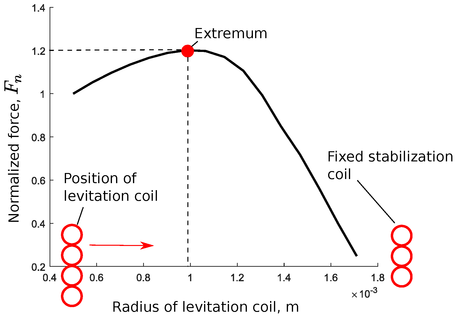
3.2. Levitation Force

With the knowledge of the eddy current distribution law, the levitation dimensionless force was calculated using the following equation [24]:
F m ( λ ) = s = 1 n j = 1 N η s j M ¯ s j ( x ¯ 1 , x ¯ 2 , ( 1 + λ κ ) χ ) λ ,
where λ = q 3 / h l is the dimensionless displacement along the X 3 axis, which is characterized by the generalized coordinate q 3 , η s j = I ¯ s I ¯ c j R ¯ c j / χ , I ¯ s = I s / I c 1 and I ¯ c j = I c j / I c 1 are the dimensionless currents, R ¯ c j = R c j / R c 1 , R c 1 is the radius of the first winding of the levitation coil, χ = h l / R e is the scaling factor, and M ¯ s j / λ is the derivative of dimensionless mutual inductance with respect to λ .
The derivative of dimensionless mutual inductance is defined as follows:
M ¯ s j = 1 π 0 2 π 1 + x ¯ 1 · cos φ + x ¯ 2 · sin φ ρ ¯ 1.5 Ψ ( k ) k d φ ,
where
ρ ¯ = 1 + 2 ( x ¯ 1 · cos φ + x ¯ 2 · sin φ ) + x ¯ 1 2 + x ¯ 2 2 ;
Ψ ( k ) = 1 k 2 2 K ( k ) E ( k ) ;
k 2 = 4 ν j ρ ¯ ( ν j ρ ¯ + 1 ) 2 + ν j 2 x ¯ 3 2 ,
where ν j = R e / R c j , R c j is the radius of the j-coil filament, x ¯ 1 , x ¯ 2 , and x ¯ 3 are the components of the radius vector r in base e ̲ z (see Equation (3)), which are defined in dimensionless form as x ¯ 1 = x 1 / R e , x ¯ 2 = x 2 / R e and x ¯ 3 = x 3 / R e .
The derivative of dimensionless mutual inductance with respect to x ¯ 3 is:
M ¯ s j x ¯ 3 = 1 π 0 2 π 1 + x ¯ 1 · cos φ + x ¯ 2 · sin φ ρ ¯ 1.5 Φ ( k ) d φ ,
where
Φ ( k ) = d d x ¯ 3 Ψ ( k ) k = 1 k 2 2 k 2 2 ( 1 k 2 ) E ( k ) K ( k ) d k d x ¯ 3 ,
d k d x ¯ 3 = ν j 2 x ¯ 3 4 ν j ρ ¯ ( 1 + ν j ρ ¯ ) 2 + ν j 2 x ¯ 3 2 3 / 2 .
Substituting x ¯ 3 = λ κ χ into Equation (10), the desired equation for the derivative of dimensionless mutual inductance with respect to λ is derived.
It is interesting to note that if the levitation coil diameter is equal to zero ( d l = 0 ), the levitation force disappears. However if the levitation coil diameter is the same as the stabilization coil ( d l = d s ), the levitation force presents its minimum value due to the minimization of the magnetic flux generated by both coils. Hence, between these two limit points was found a particular value for the levitation coil diameter, where the levitation force could reach its maximum value. To exemplify this effect, the levitation force was calculated with the following range of levitation coil radius, which was 0.5 m m to 1.8 m m , in this case, a square shaped proof mass with a side length of 2.8 mm and a levitation height of 84 μ m was used. The result of the calculation is presented in Figure 10. The levitation force is presented in the normalized value F n = F m ( 1 ) / F m 0 ( 1 ) , where F m 0 ( 1 ) is calculated for a 0.5   m m radius of the levitation coil. The analysis of Figure 10 shows the existence of a levitation force extremum and, as a result, it confirms the fact that the fabricated two coil design is the optimum system for the square shape PM levitation with a side length of 2.8 mm.

4. Conclusions

In this paper we developed a control circuit for application to inductive levitation micro-actuators. The developed control circuit was fabricated on a four-layer PCB board with a size of 60 × 60 × 25 m m , which is comparable with the levitation micro-actuators dimensions. The developed circuit was able to generate an AC current with squared shape in a range of frequency from 8 to 43 M Hz and with peak-to-peak amplitude up to 420 m A . The fabricated ILMA, designed with two solenoidal coils, which includes the levitation and the stabilization coils, with 2 mm and 3.8 mm in diameters, respectively, was excited using the developed control circuit. We demonstrated the successful levitation of disc shaped PM with diameters of 2.8   m m and 3.2   m m and, for the first time, a square shaped PM of a side length of 2.8   m m at an excitation frequency of 10 M Hz was levitated. The results confirmed the efficiency of the proposed circuit design and its compatibility with micro-actuation systems.
Applying the quasi-finite element method, we simulated the induced eddy current distribution using a square shaped PM of a side length of 2.8   m m . The simulation showed that maximum magnitudes of the eddy current are concentrated along the edge of the PM and in its central part along the circle with the same diameter as the levitation coil. The numerical analysis of the force interaction between the coils and the levitated proof mass along with the vertical direction showed the existence of a levitation force extremum and, as a result, it confirmed the fact that the fabricated two coil design provided the optimum coil design for the levitation of the square shape PM with a side length of 2.8 mm.

5. Materials

The printed circuit board (PCB) was manufactured by Beta Layout GmbH (Aarbergen, Germany). The basic electronic components such as capacitors, diodes, resistors, switches, etc. were acquired in house. The main electronic components for the control circuit are listed below:
  • Voltage regulator, chip 78L05 IC1 (National Semiconductors, Danbury, CT, USA) [28];
  • Frequency oscillator, chip LTC6905 (Linear Technology, Milpitas, CA, USA) [29];
  • Frequency divider, chip D-FF-IC3 (Texas Instruments, Dalas, TX, USA) [30];
  • High-power output current feedback amplifier THS3491 (Texas Instruments, Dalas, TX, USA) [31].

Author Contributions

Conceptualization, A.V. and K.P., writing—review and editing, K.P.; writing–original draft preparation, methodology and visualization, V.V.; investigation, V.V. and S.W.; validation, A.V.; resources, K.P. and M.K; supervision, K.P., M.K. and J.K.; project administration, K.P. and M.K.; funding acquisition, K.P. All authors have read and agreed to the published version of the manuscript.

Funding

This research was funded by the German Research Foundation grant number KO 1883/37-1.

Conflicts of Interest

The authors declare no conflict of interest.

Abbreviations

The following abbreviations are used in this manuscript:
ILMAInductive Levitation Micro-Actuator
PMProof Mass
MLMAMagnetic Levitation Micro-Actuator
ELMAElectric Levitation Micro-Actuator

References

  1. Jin, J.; Yih, T.C.; Higuchi, T.; Jeon, J.U. Direct electrostatic levitation and propulsion of silicon wafer. IEEE Trans. Ind. Appl. 1998, 34, 975–984. [Google Scholar] [CrossRef]
  2. Murakoshi, T.; Endo, Y.; Fukatsu, K.; Nakamura, S.; Esashi, M. Electrostatically levitated ring-shaped rotational gyro/accelerometer. Jpn. J. Appl. Phys. 2003, 42, 2468–2472. [Google Scholar] [CrossRef]
  3. Han, F.T.; Liu, Y.F.; Wang, L.; Ma, G.Y. Micromachined electrostatically suspended gyroscope with a spinning ring-shaped rotor. J. Micromech. Microeng. 2012, 22, 105032. [Google Scholar] [CrossRef]
  4. Poletkin, K.V.; Asadollahbaik, A.; Kampmann, R.; Korvink, J.G. Levitating Micro-Actuators: A Review. Actuators 2018, 7, 17. [Google Scholar] [CrossRef]
  5. Coombs, T.A.; Samad, I.; Ruiz-Alonso, D.; Tadinada, K. Superconducting micro-bearings. IEEE Trans. Appl. Supercond. 2005, 15, 2312–2315. [Google Scholar] [CrossRef]
  6. Lu, Z.; Poletkin, K.; den Hartogh, B.; Wallrabe, U.; Badilita, V. 3D micro-machined inductive contactless suspension: Testing and modeling. Sens. Actuators Phys. 2014, 220, 134–143. [Google Scholar] [CrossRef]
  7. Poletkin, K.V.; Lu, Z.; Moazenzadeh, A.; Mariappan, S.G.; Korvink, J.G.; Wallrabe, U.; Badilita, V. Polymer Magnetic Composite Core Boosts Performance of Three-Dimensional Micromachined Inductive Contactless Suspension. IEEE Magn. Lett. 2016, 7, 1–3. [Google Scholar] [CrossRef]
  8. Shearwood, C.; Williams, C.B.; Mellor, P.H.; Chang, K.Y.; Woodhead, J. Electro-magnetically levitated micro-discs. In Proceedings of the IEE Colloquium on Microengineering Applications in Optoelectronics, London, UK, 7–27 February 1996; pp. 6/1–6/3. [Google Scholar] [CrossRef]
  9. Xiao, Q.; Wang, Y.; Dricot, S.; Kraft, M. Design and experiment of an electromagnetic levitation system for a micro mirror. Microsyst. Technol. 2019, 25, 3119–3128. [Google Scholar] [CrossRef]
  10. Shearwood, C.; Ho, K.Y.; Williams, C.B.; Gong, H. Development of a levitated micromotor for application as a gyroscope. Sens. Actuators A Phys. 2000, 83, 85–92. [Google Scholar] [CrossRef]
  11. Su, Y.; Xiao, Z.; Ye, Z.; Takahata, K. Micromachined Graphite Rotor Based on Diamagnetic Levitation. IEEE Electron. Device Lett. 2015, 36, 393–395. [Google Scholar] [CrossRef]
  12. Garmire, D.; Choo, H.; Kant, R.; Govindjee, S.; Sequin, C.; Muller, R.; Demmel, J. Diamagnetically levitated MEMS accelerometers. In Proceedings of the TRANSDUCERS 2007—2007 International Solid-State Sensors, Actuators and Microsystems Conference 2007, Lyon, France, 10–14 June 2007; pp. 1203–1206. [Google Scholar]
  13. Dieppedale, C.; Desloges, B.; Rostaing, H.; Delamare, J.; Cugat, O.; Meunier-Carus, J. Magnetic bistable micro-actuator with integrated permanent magnets. Proc. IEEE Sens. 2004, 1, 493–496. [Google Scholar]
  14. Abadie, J.; Piat, E.; Oster, S.; Boukallel, M. Modeling and experimentation of a passive low frequency nanoforce sensor based on diamagnetic levitation. Sens. Actuators A Phys. 2012, 173, 227–237. [Google Scholar] [CrossRef]
  15. Poletkin, K.V.; Lu, Z.; Wallrabe, U.; Korvink, J.G.; Badilita, V. A qualitative technique to study stability and dynamics of micro-machined inductive contactless suspensions. In Proceedings of the 2017 19th International Conference on Solid-State Sensors, Actuators and Microsystems (TRANSDUCERS), Kaohsiung, Taiwan, 18–22 June 2017; pp. 528–531. [Google Scholar] [CrossRef]
  16. Sari, I.; Kraft, M. A MEMS Linear Accelerator for Levitated Micro-objects. Sens. Actuators A Phys. 2015, 222, 15–23. [Google Scholar] [CrossRef]
  17. Poletkin, K.; Lu, Z.; Wallrabe, U.; Badilita, V. A New Hybrid Micromachined Contactless Suspension With Linear and Angular Positioning and Adjustable Dynamics. J. Microelectromech. Syst. 2015, 24, 1248–1250. [Google Scholar] [CrossRef]
  18. Xu, Y.; Cui, Q.; Kan, R.; Bleuler, H.; Zhou, J. Realization of a Diamagnetically Levitating Rotor Driven by Electrostatic Field. IEEE/ASME Trans. Mechatron. 2017, 22, 2387–2391. [Google Scholar] [CrossRef]
  19. Xu, Y.; Zhou, J.; Bleuler, H.; Kan, R. Passive diamagnetic contactless suspension rotor with electrostatic glass motor. Micro Nano Lett. 2019, 14, 1056–1059. [Google Scholar] [CrossRef]
  20. Chen, X.; Keskekler, A.; Alijani, F.; Steeneken, P.G. Rigid body dynamics of diamagnetically levitating graphite resonators. Appl. Phys. Lett. 2020, 116, 243505. [Google Scholar] [CrossRef]
  21. Kratt, K.; Badilita, V.; Burger, T.; Korvink, J.; Wallrabe, U. A fully MEMS-compatible process for 3D high aspect ratio micro coils obtained with an automatic wire bonder. J. Micromech. Microeng. 2010, 20, 015021. [Google Scholar] [CrossRef]
  22. Lu, Z.; Poletkin, K.; Wallrabe, U.; Badilita, V. Performance Characterization of Micromachined Inductive Suspensions Based on 3D Wire-Bonded Microcoils. Micromachines 2014, 5, 1469–1484. [Google Scholar] [CrossRef]
  23. Poletkin, K.; Lu, Z.; Wallrabe, U.; Korvink, J.; Badilita, V. Stable dynamics of micro-machined inductive contactless suspensions. Int. J. Mech. Sci. 2017, 131–132, 753–766. [Google Scholar] [CrossRef]
  24. Poletkin, K. Static Pull-in Behavior of Hybrid Levitation Micro-Actuators: Simulation, Modelling and Experimental Study. arXiv 2020, arXiv:2001.09428. [Google Scholar]
  25. Poletkin, K.V. Levitation Micro-Systems: Applications to Sensors and Actuators, 1st ed.Springer: Berlin/Heidelberg, Germany; p. 145. [CrossRef]
  26. Poletkin, K.V.; Korvink, J.G. Efficient calculation of the mutual inductance of arbitrarily oriented circular filaments via a generalisation of the Kalantarov-Zeitlin method. J. Magn. Magn. Mater. 2019, 483, 10–20. [Google Scholar] [CrossRef]
  27. Lu, Z.; Jia, F.; Korvink, J.; Wallrabe, U.; Badilita, V. Design optimization of an electromagnetic microlevitation System based on copper wirebonded coils. In Proceedings of the 2012 Power MEMS, Atlanta, GA, USA, 2–5 December 2012; pp. 363–366. [Google Scholar]
  28. National Semiconductors. Data Sheet: LM78LXX Series3-Terminal Positive Regulators. Available online: http://users.ece.utexas.edu/~valvano/Datasheets/LM78L05.pdf (accessed on 9 October 2020).
  29. Linear Technologies. Data Sheet: LTC6905—17 MHz to 170 MHz Resistor Set SOT-23 Oscillator. Available online: https://www.analog.com/media/en/technical-documentation/data-sheets/6905fd.pdf (accessed on 9 October 2020).
  30. Texas Instruments. Data Sheet: D-FFIC3—SN74LVC1G74 Single Positive-Edge-Triggered D-Type Flip-Flop with Clear and Preset. Available online: https://www.ti.com/lit/ds/symlink/sn74lvc1g74.pdf (accessed on 9 October 2020).
  31. Texas Instruments. Data Sheet: THS3491—900-MHz, 500-mA High-Power Output Current Feedback Amplifier. Available online: https://www.ti.com/lit/ds/symlink/ths3491.pdf (accessed on 9 October 2020).
Figure 1. Development of control circuit for ILMA/Figures/scheme_circuit.
Proceedings 64 00039 g001
Figure 2. H-bridge configuration using two current amplifiers, at the output of the frequency divider.
Proceedings 64 00039 g002
Figure 3. Electronic circuit of oscillator (implemented on a chip LTC6905 (b)), connected to the voltage regulator (implemented on a chip LM7805 (a)) with the voltage limit, which is up to 5.5 V. In the output of the frequency oscillator is located the frequency divider (implemented on an chip SN74LVC1G74 (c)).
Proceedings 64 00039 g003
Figure 4. Control circuit built in a four-layer printed circuit board (PCB): The location of the voltage regulator (LM7805), and the frequency oscillator (LTC6905) is marked by (a); the location of the oscillator divisor (SN74LVC1G74) is marked by (b); and the location of the two amplifiers is marked by (c).
Proceedings 64 00039 g004
Figure 5. Experimental setup: The device is mounted on the optical table and successfully levitated the disc shaped proof mass of a 3.2 m m diameter.
Proceedings 64 00039 g005
Figure 6. Measurements of the levitation height for three proof masses (PM) versus the coil currents.
Proceedings 64 00039 g006
Figure 7. Square shaped proof mass of a side length of 3.4 m m is meshed by 2500 circular elements.
Proceedings 64 00039 g007
Figure 8. 3D geometrical scheme of the actuator for simulation mimicking the real prototype of the actuator shown on the right side of the figure: { X k } ( k = 1 , 2 , 3 ) is the fixed coordinate frame.
Proceedings 64 00039 g008
Figure 9. The distribution of magnitudes of eddy current with respect to unit vectors of e 1 x and e 2 x of the base e ̲ x : (a) 2D plot; (b) 3D plot with intensity bar characterizes the value of dimensionless magnitude of the eddy current.
Proceedings 64 00039 g009
Figure 10. The normalized levitation force F n vs a radius of levitation coil for the square shaped proof mass with a side length of 2.8 mm: The extremum of levitation force corresponding to a 1.0 mm radius of levitation coil is equal to 1.2.
Proceedings 64 00039 g010
Publisher’s Note: MDPI stays neutral with regard to jurisdictional claims in published maps and institutional affiliations.

