Proceeding Paper

Design of Electromechanical Actuators for Large Sized Valves †

by
Tobias Vonderbank
* and
Katharina Schmitz
Institute for Fluid Power Drives and Systems (ifas), RWTH Aachen University, 52074 Aachen, Germany
*
Author to whom correspondence should be addressed.
Presented at the First International Electronic Conference on Actuator Technology: Materials, Devices and Applications, 23–27 November 2020; Available online: https://iecat2020.sciforum.net/.
Proceedings 2020, 64(1), 37; https://doi.org/10.3390/IeCAT2020-08477
Published: 20 November 2020

Abstract

:
Increased performance in modern hydraulics is achieved by crucial investigation of possible enhancements of its components. Previous research has pointed out that electromechanical actuators can represent an alternative to hydraulic pilot control systems. Since an additional pilot circuit is complex and expensive, there are advantages, especially for systems which currently rely on a separate hydraulic pilot circuit. Actuators for large sized valves have to meet various requirements, such as applying high forces over large strokes. A functional structure of the “valve and its actuation system” has been derived to define these requirements effectively in order to develop an innovative valve actuator. The general function of the system is divided into elementary functions using this design method. Besides common actuators consisting of a switch and an energy converter, even more alternative actuator designs were pointed out by the comprehensive analysis of the functional structure. Since every actuator needs to be attached on any regular hydraulic valve, the designed actuator is presented, and the most significant construction details are explained. In conclusion, this paper summarizes significant steps during the design process of alternative electromechanical actuators of hydraulic valves. It is intended to serve as a basis for the further development of innovative valve actuators.

1. Introduction

In modern hydraulic systems, large sized control valves are normally operated via smaller pilot valves. This type of actuation is characterized by very high realizable forces and large possible strokes. If the minimum working pressure of approximate 4 bar is not ensured during the switching process of the main valve, the resulting force is insufficient to switch the valve [1]. Therefore, the pilot valve cannot be internally supplied [1]. In this case, the pilot valve has to be externally supplied. This requires a separate hydraulic circuit, which is normally operated as a constant pressure system [1]. New electromechanical actuators can be developed to replace the external pilot circuit, therefore enhancing the hydraulic system. The requirements, which need to be fulfilled by the actuation system, strongly depend on the hydraulic system. Therefore, each design of a new valve actuator needs to be adapted to the considered system to achieve the most suitable solution. The presented paper is intended to give an overview over the design process of new electromechanical valve actuators. This paper is focused on the common definition of the requirements based on acting forces, as well as on the identification of innovative optimization potential. Therefore, the holistic system of the valve and its actuation system is investigated using the design method of functional structures explained in VDI 2222 Methodic development of solution principles [2], Paul/Beitz [3], or Koller[4]. The potential of functional structures for the design of innovative valve actuators is shown, while the graphical representation is extended by further elementary functions. More innovative valve actuators, considering the whole system of the valve and its actuation system, are taken into account by this extended functional structure.
Based on a presented electromechanical actuator, it is explained which further features need to be considered during the design process. Further forces, which are applied by the implementation of an electromechanical actuator, are evaluated through carried out measurements. It is explained how these can be held negligible small.

2. Elementary Function of a Directional Control Valve

Using the design method of functional structures, the general function of a technical system is divided, consequently, into elementary functions. In presented paper, the displayed symbols according to Table 1 are used to represent them. The general function is divided until a functional structure sufficient for the aimed design process is obtained.
According to Backé, the general function of a control valve can be formulated as: “Opening/Closing of different flow paths” [5]. Since the hydraulic system often is embedded into a higher-level control system, the main function can be extended to “Opening/Closing of different flow paths according to an electrical control signal”. In the first step, this main function can be divided into two main functions, namely “Conduction of hydraulic energy depending on the position” and “Positioning of the spool according to an electric signal”, as shown in Figure 1.
The conduction of hydraulic energy is realized by the geometry of the spool and its positioning by the actuation system of the valve. Since the positioning of the spool is realized by a controlled force application, the function can be reformulated to “Applying force to the spool according to an electric signal”.

3. Design of New Valve Actuation Systems

Actuators need to overcome all forces opposing the movement or tending to close the valve to ensure the general function. Forces acting on the spool of a pilot operated 4/3 directional control valve are shown in Figure 2.
In addition to friction forces FFriction and inertia forces FInertia, the actuator also needs to overcome the spring forces FSpring and the flow forces FFlow, which normally act in closing direction [6,8]. The spring forces must be high enough, so that the valve is able to close at any given operation condition [6,8]. A preload on the spring prevents the spool from overshooting [6,8]. The flow force mostly represents the most significant resistance of these forces [9]. In addition, an additional inherent force FPressure is caused by the fluid in the passive pilot chamber, as is the case of a pilot operated valve. Fluid is displaced by the movement of spool. A pressure rise in the passive pilot chamber can occur depending on the hydraulic resistance of the drain line.

3.1. Functional Structure of a Pilot Operated Large Sized Valve

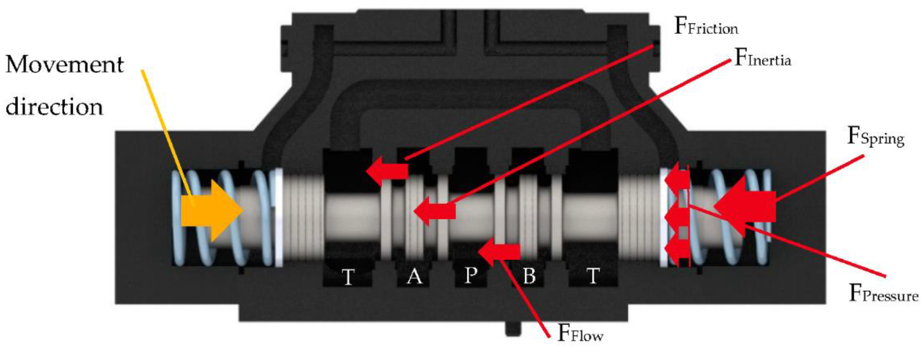
A functional structure of a 4/3 directional control valve has been derived in Figure 3 based on the two main functions of a directional control valve according to 
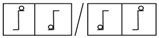
Figure 1. The notation of elementary functions according to Table 1 is used in following figure.
The functional structure can be divided into different subsystems. Subsystem 1) represents the functions attributed to the spool geometry. The flow rate which is entering the system through port P is conducted by the metering edges a) to the working ports of the valve. During the flow conduction a part of the energy is transformed into mechanical energy b), which acts as flow force on the spool. This force normally tends to close the valve. Leaving the subsystem 1), the fluid enters a not further specified hydraulic system. Fluid flows back into the tank resulting in additional flow forces.
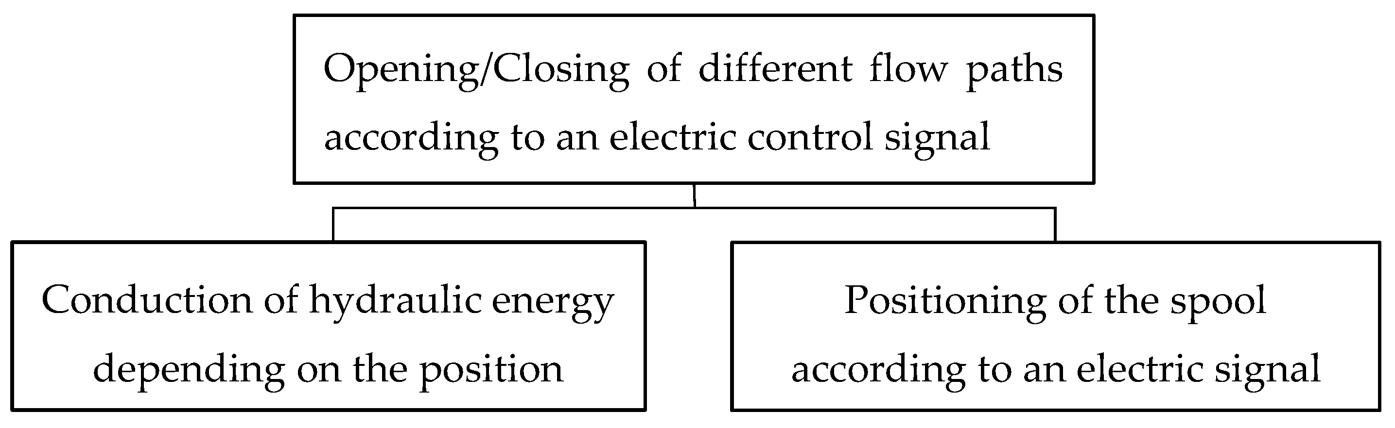
During the positioning of the spool, the actuation unit needs to apply a force larger than all resistance forces acting on the spool. As shown in Figure 2, these consist of flow forces FFlow, friction forces FFriction, inertia forces FInerta, spring forces FSpring, and forces resulting of the hydraulic resistance of the drain line of the passive pilot chamber FPressure. Most of these forces are shown leaving the functional structure, since they represent dissipation (friction, inertia and further resistance forces). Flow forces are applied in the valve and are acting on the spool, therefore being displayed on the functional structure as generated forces, which are subtracted from the actuation system force. The remaining force acts against the centering spring, while the spool is deflected into its working position.
The mechanical energy is stored in the spring c), as long as the actuation system provides sufficient force. If the actuation force is reduced, the stored energy is released, thus centering the spool. The stored energy is, according to the spring stiffness, a function of the stroke, which is why an information flow is drawn from the spring c) to the metering edges a).
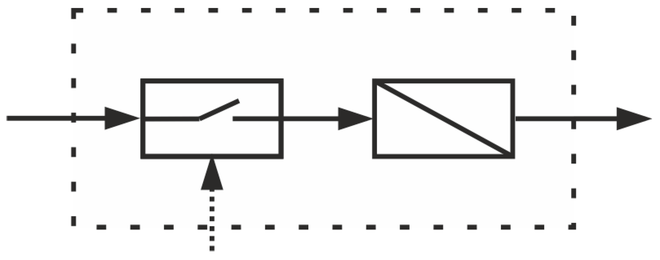
The subsystem 2) needs to be analyzed in detail to design a direct electromechanical valve actuation system. This subsystem consists at least out of two essential functions, as shown in Figure 4 [10].
Every actuator consists at least of a switch and an energy converter [10]. This can be a pilot operation circuit where the pilot valve is the switch and the energy conversion is realized in the pilot chamber. Focusing on the design of an electromechanical valve actuation system, the energy converter is electromechanical, such as solenoids or electrical motor. An evaluation on electromechanical converters was carried out to analyze their suitability for the given application. As a result, an electrical motor, followed by a mechanical component to convert rotary into translatory movement, was the optimal concept.

3.2. Designed Electromechanical Vavle Actuation System

A prototype of an electromechanical valve actuator for hydraulic valves has been designed to identify the most critical and important construction details (Figure 5). It is based on a stepper motor (1). The rotary energy is converted to a linear movement by a steep threaded rod (2) and the corresponding nut (3). The model is equipped with necessary sensors for measurements of displacement and force signals (4 and 5). Since it was designed for the control of a large sized directional control valve of nominal size 25 in a flow-controlled system, forces up to 500 N are realizable with the actuator.
As seen in Figure 5, the designed electromechanical actuator is mounted outside the valve. This makes it possible to apply to every common valve by adjusting the valve connector (6).

3.3. Design Features of the Electromechanical Valve Actuation System

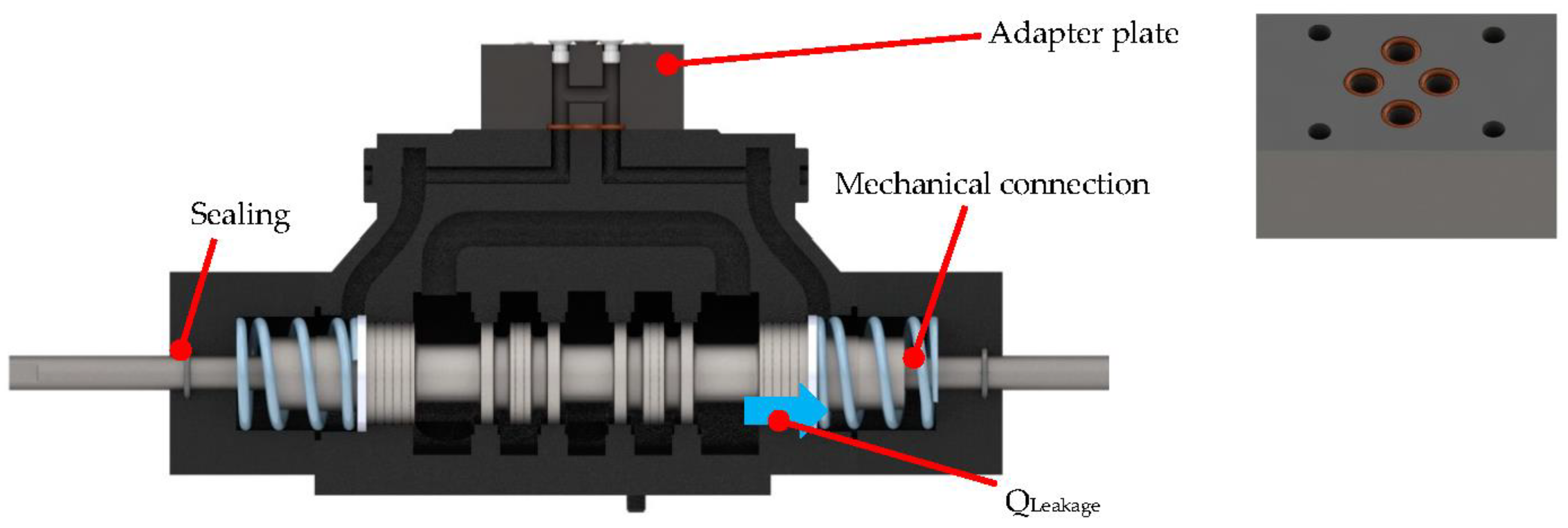
Certain design features must be taken into account if the valve actuator is designed independently from the valve. These result from the design of the valve and can cause additional unwanted forces if they are not considered properly. To highlight these features, a sectional view of a regular pilot operated valve is shown in Figure 6. The spool of the valve is extended at both ends by a rod, creating a mechanical connection to the outside of the valve. These connections are required as the valve is switched electromechanically.
In the case of externally attached actuators, mechanical connectors are necessary to transmit tensile and compressive forces required for the actuation of the valve. Actuators, which are able to induce both forces, are therefore attached only on one side of the valve. In this configuration, the spool has to be balanced, taking into account the pressure forces at the front sides. To ensure that the pressure in both sides is identical, the pilot chambers needs to be short circuited. Since the actuator design is externally attached, an internal connection between both pilot chambers of the valve is not possible. Therefore, an adapter plate is mounted on the top of the valve instead of the pilot valve. As, the mechanical connection reduces the pressurized area, it should be implemented on both sides.
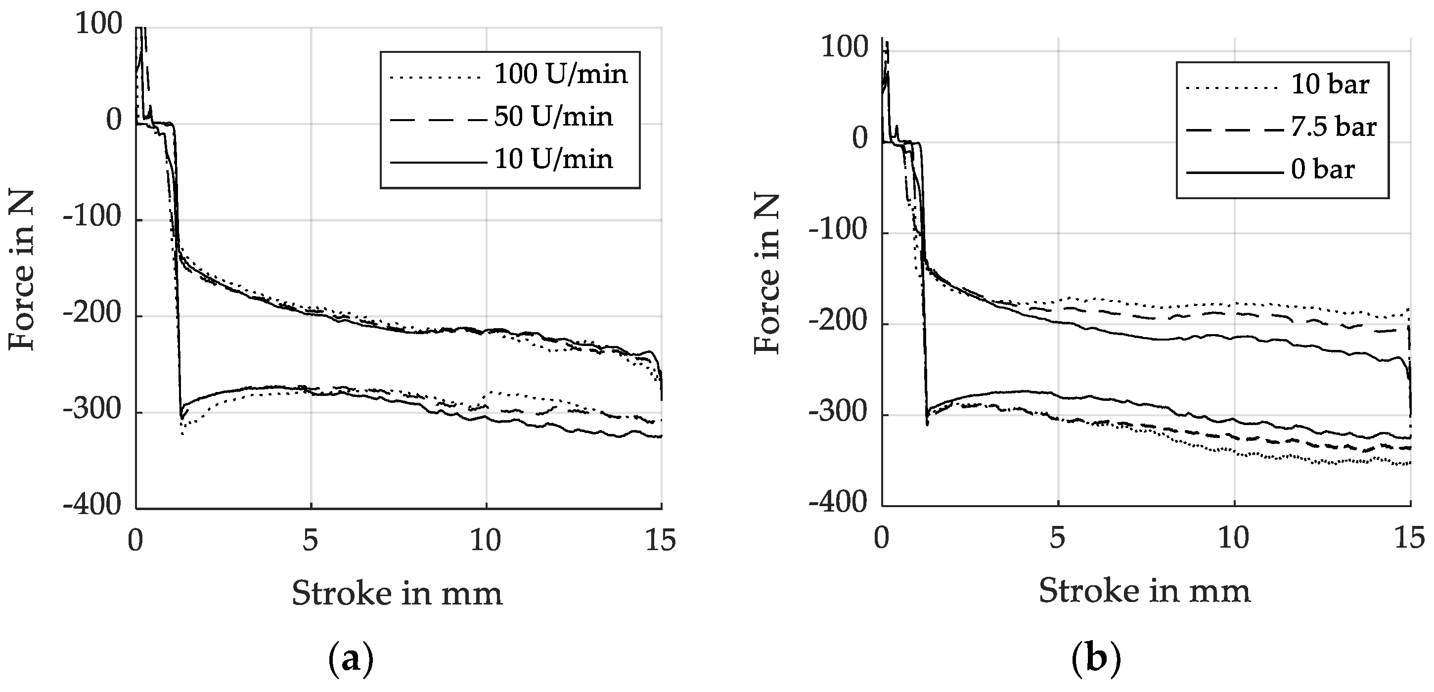
Short-circuiting both pilot chambers with each other has an additional effect. During the movement of the spool, one chamber is expanded, whereas the other is contracted. Therefore, fluid must be able to enter or exit the chambers. This action would require a compensation volume, but using the adapter plate, the displaced volume in one chamber is compensated in the other, thus maintaining a constant volume. No additional volume is necessary. Enabling the fluid to oscillate between the chambers, it needs to overcome the inherent resistance. Therefore, a small pressure difference between the two chambers arises. This needs to be considered in the design of the electromechanical actuator. To investigate this effect, the actuator was driven with different speeds, and the required force was measured. The results are shown in Figure 7a. The necessary force to move the spool at even tenfold the actuator speed does not increase significantly. It can, therefore, be concluded that this influence is extremely small considering the other factors.
Additional sealings on the caps are necessary to avoid external leakage, leading to further friction forces to be overcome by the actuator. These forces strongly depend on the pressure in the pilot chambers. Further measurements have been conducted to investigate this effect. The force requirements by different pressure levels in the pilot chamber is illustrated in Figure 7b.
As can be seen in the figure, this effect is not negligible. Even a chamber pressure of 10 bar leads to a significant increase of the required actuator force. Therefore, the pressure in the pilot chambers have to be reduced as much as possible. The pressure in the pilot chamber is adjusted to the pressure at the T port of the valve since there is a leakage flow over the spool. Therefore, the maximum pressure at the tank line of the valve must be considered during the design of outside attached actuators. In case of systems where the pressure at the valve T port can reach high values, an additional drain line in the adapter plate will ensure low pressure in the pilot chamber. The aforementioned design features are only valid for outside attached actuators, which are normally designed independently from the valve geometry. The additional sealing, and therefore the draining line, becomes redundant with the development of an actuation system, which can be pressurized. The adapter plate becomes unnecessary if a direct connection between both chambers is provided.

3.4. Innovative Electromechanical Valve Actuation System

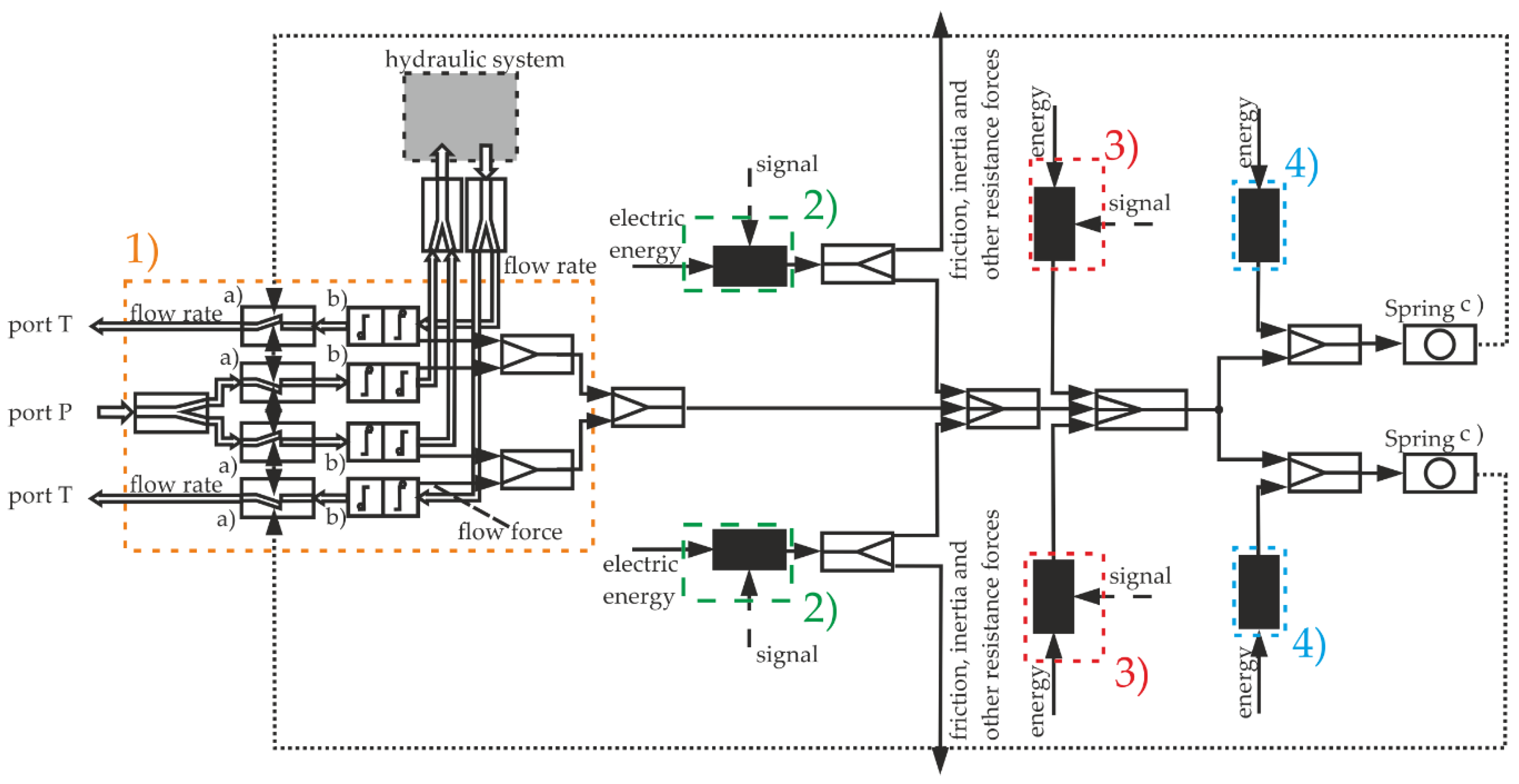
The previously presented actuator is one possible solution while focusing on the functional structure of an actuator. A holistic view of the functional structure of a “valve and its actuation system” leads to further innovative solutions. In the following, Figure 8, the functional structure of the “valve and its actuation system” was extended by two additional subsystems, 3) and 4).
Other than the additional subsystems, the functional structure is kept the same. Subsystem 1) represents the valve and subsystem 2) the main actuator. New valve actuation systems can be derived based on this functional structure because the requirements of the individual actuators change by combining various subsystems.
Solutions proposed by the subsystem 3) cover all actuation systems, which are extended by an additional actuator 3) to keep the spool in position when it has reached the desired stroke. Therefore, the main actuator (subsystem 2)) does not need to constantly apply the necessary force. The actuator only needs to surpass the opposing forces for a short time. After that, the spool is held in position by the actuator 3). It is conceivable for a design that the actuator 3) holds the spool in position by means of clamping forces. In this case, the actuator 3) only needs to realize relatively small strokes. Due the clamping movement can be realized orthogonal to the spool movement. One example where the clamping idea is realized is a piezoelectric inchworm motor
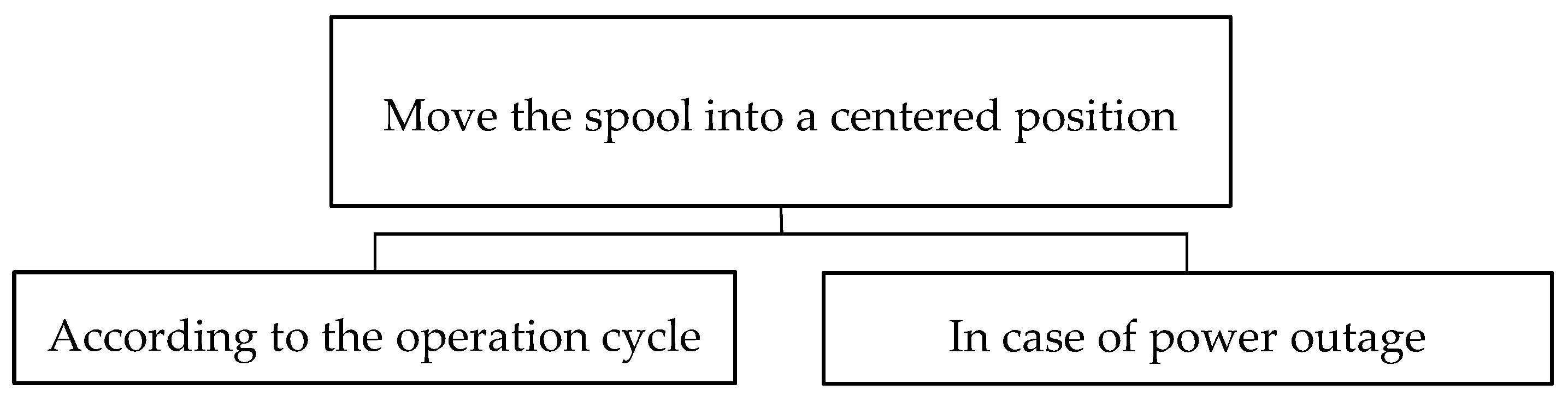
Solutions resulting of subsystem 4) seem more promising. The general function of the springs is to move the spool into a defined position. In the case of the here analyzed 4/3 directional control valve, it is the centered position. In the functional structure in Figure 8, the springs are displayed as accumulators c). A closer look to the general function of the springs shows that there are two relevant operations. On the one hand, the springs need to center the spool according to the operation cycle, while, one the other hand, they need to center the spool in case of failure, as in a power outage. Therefore, the general function can be divided into two different functions, according to Figure 9.
In common pilot operated valves, providing energy for the switching process and compressing the springs takes place simultaneously, while moving the spool into the end position a part of the actuator’s energy is used to compress the springs. This energy is stored in the springs and is required for the reset process. The time dependency can be solved by the separation and redistribution of the spring functions into further components. The first function can be covered by the main actuator using a proportional actuator, like the one present before. Therefore, the springs only must center the spool in case of power outage. Thus, the energy stored in the springs only comes to effect in case of an error. They remain compressed most of the time by the additional force of subsystem 4). The requirements for the applied force of the switching actuator decrease as the high spring forces can be temporarily removed during normal operation.
Two principal solutions turned out to be the most suitable. In one alternative, the springs are preloaded by the main actuator while being held compressed by magnets. Since magnets are optimal for applying high forces at zero gap, they comply perfectly the requirements for this function. During an initial start of the system, the main actuator moves the spool in each end position to compress the springs. This can be done with low velocity. Therefore, the necessary power is reduced. Reaching the end position, the magnets are activated and ensure the holding of the compressed springs. Subsequently, the spool can be moved by the main actuator without applied spring forces. In case of power failure, the magnets are deactivated, causing the springs to decompress and thus centering the spool. This concept is ideal for an actuator, based on a stepper motor, since it can provide large torque during a slow rotation speed. During further operation, the actuator does not need to work against the spring forces anymore. Therefore, the necessary power is reduced drastically.
In another alternative solution an extra chamber containing the spring is designed to preload these by application of hydraulic energy. Hydraulic fluid can be diverted from the main system during high pressure phases, since the time dependency is solved, thus avoiding an additional pilot circuit. Hydraulic pressure controlled by two valves regulate the energy stored in the springs. The first valve is placed to separate the spring chamber from the hydraulic main system, ensuring the preload to remain even in phases of low pressure. The second valve ensures the pressure relief of the spring chamber to the tank in case of a power outage. The missing hydraulic energy in the spring chamber releases the stored energy in the springs, forcing them to expand and thereby centering the spool. Since the springs are preloaded by another actuator during normal operation, the force requirement in the electromechanical actuation system is reduced.

4. Discussion

During the design process of innovative electromechanical valve actuation systems, the functional structure represents an important design method. Even if the investigation of the acting forces is indispensable, the functional structure enables a holistic view over the valve and its actuation system. This allows not only the design based on known forces but also taking into account all other components and other system-related aspects. Separation and redistribution of elementary functions of different components enable further optimization not restricted to the reduction of flow forces. This is an effective approach to reduce the requirements during the design process of valve actuation systems; see, for example, Reference [9,11]. The functional structure derived in this paper leads to a solution where the spring forces are compensated, thus reducing the requirements of the main actuator massively. This proposed solution can only be implemented in actuators which can switch the spool actively in the desired positions. The presented actuator also fulfills this requirement. Therefore, an expansion and further investigation should be carried out, since it is a concept with broader potential. Even if the functional structure may be extended further, the derived structure already contains some significant correlations, which can help during the development of further valve actuator systems.

5. Conclusions

In the presented paper, the design process of a new electromechanical valve actuator for large sized directional control valves was investigated. An innovative electromechanical valve actuation system was generated focusing on the derivation of the functional structure and identification of special design features. Measurements were carried out on a prototype and investigated to evaluate special design features which need to be considered during the design process. Effects in the pilot chamber must be considered for outside mounted electromechanical actuators. Since additional sealings are necessary, both pilot chambers are to be short-circuited and released against the tank to decrease the load on the actuator, due to the sealing friction forces. Since the pilot chambers are expanded and contracted during the movement, short-circuiting is necessary to keep the total volume constant. Therefore, no compensation volume is required.
The functional structure was extended aiming to point out further innovative solutions. These consider the whole system of the valve and its actuation system. Proposing a solution, where the designed electromechanical actuator is extended by magnets to keep the springs compressed, points out how useful the functional structure can be.

Acknowledgments

The IGF research project 20084N of the research association Forschungskuratorium Maschinenbau e. V.–FKM, Lyoner Straße 18, 60,528 Frankfurt am Main was supported from the budget of the Federal Ministry of Economic Affairs through the AiF within the scope of a program to support industrial community research and development (IGF) based on a decision of the German Bundestag.

Conflicts of Interest

The authors declare no conflict of interest.

References

  1. Bauer, G. Ölhydraulik: Grundlagen, Bauelemente, Anwendungen; Springer: Berlin/Heidelberg, Germany, 2009. [Google Scholar]
  2. Methodisches Entwickeln von Lösungsprinzipien. VDI 2222, 1997.
  3. Feldhusen, J.; Grote, K.-H. (Eds.) Pahl/Beitz Konstruktionslehre: Methoden und Anwendung Erfolgreicher Produktentwicklung, 8th ed.; Springer: Berlin/Heidelberg, Germany, 2013. [Google Scholar]
  4. Koller, R.; Kastrup, N. Prinziplösungen zur Konstruktion Technischer Produkte; Springer: Berlin/Heidelberg, Germany, 2013. [Google Scholar]
  5. Backé, W.; Hahmann, W. Grundlagen der Ölhydraulik: Umdr. zur Vorlesung; Institut für hydraulische und pneumatische Antriebe und Steuerungen der RWTH (IFAS): Aachen, Germany, 1972. [Google Scholar]
  6. Tatar, H. Störkräfte bei elektromagnetisch betätigte Wegeventilen. Ph.D. Thesis, Rheinisch-Westfälische Technische Hochschule Aachen, Aachen, Germany, 1974. [Google Scholar]
  7. Schrank, K.; Murrenhoff, H. Beschreibung der Strömungskraft in Längsschieberventilen mittel Impulserhaltung. O + P Fluidtechnik 2013, 4, 4–15. [Google Scholar]
  8. Backé, W.; Tatar, H. Untersuchung des Einflusses von Störkräften auf den Schaltvorgang bei Wegeventilen der Hydraulik; Westdt. Verl.: Opladen, Germany, 1975. [Google Scholar]
  9. Christoph Latour, Strömungskraft kompensation von hydraulischen Sitzventilen. Ph.D. Thesis, Rheinisch-Westfälische Technische Hochschule Aachen, Aachen, Germany, 1996.
  10. Janocha, H. Unkonventionelle Aktoren: Eine Einführung; Oldenbourg Wissenschaftsverlag GmbH: München, Germany, 2010. [Google Scholar]
  11. Schuster, G. CFD-Gestützte Maßnahmen zur Reduktion von Strömungskraft und Kavitation am Beispiel eines Hydraulischen Schaltventils; Shaker: Aachen, Germany, 2005. [Google Scholar]
Figure 1. Splitting of the general function.
Proceedings 64 00037 g001
Figure 2. Forces at the spool in accordance with Reference [6,7].
Proceedings 64 00037 g002
Figure 3. Functional structure of a valve and its actuation system.
Proceedings 64 00037 g003
Figure 4. Minimal functional structure of an actuation system according to Reference [10].
Proceedings 64 00037 g004
Figure 5. Designed electromechanical valve actuation system.
Proceedings 64 00037 g005
Figure 6. Special design features for an outside mounted electromechanical actuation system.
Proceedings 64 00037 g006
Figure 7. (a) Influence of actuator speed on applied forces. (b) Relation between pressure level and friction forces.
Proceedings 64 00037 g007
Figure 8. Extended functional structure of “valve and its actuation system”.
Proceedings 64 00037 g008
Figure 9. Divided general function of the springs.
Proceedings 64 00037 g009
Table 1. Symbols of elementary functions in accordance with Reference [4].
Proceedings 64 00037 i001separate/connect material flow Proceedings 64 00037 i002energy flow
Proceedings 64 00037 i003link/divide material flow Proceedings 64 00037 i004material flow
Proceedings 64 00037 i005reduce/increase energy of material flow Proceedings 64 00037 i006information flow
Proceedings 64 00037 i007link/divide energy flow Proceedings 64 00037 i008store energy
Proceedings 64 00037 i009separate/connect energy flow Proceedings 64 00037 i010subsystem
Proceedings 64 00037 i011convert energy flow Proceedings 64 00037 i012not further specified hydraulic system
Publisher’s Note: MDPI stays neutral with regard to jurisdictional claims in published maps and institutional affiliations.

