Proceeding Paper

Characteristics of Ammonia/Hydrogen Premixed Combustion in a Novel Linear Engine Generator †

1
Department of Mechanical Engineering, School of Engineering, University of Birmingham, Edgbaston, Birmingham B15 2TT, UK
2
School of Naval Architecture, Ocean & Civil Engineering, Shanghai Jiao Tong University, Shanghai 200240, China
*
Author to whom correspondence should be addressed.
Presented at the First World Energies Forum, 14 September–05 October 2020; Available online: https://wef.sciforum.net/.
Proceedings 2020, 58(1), 2; https://doi.org/10.3390/WEF-06925
Published: 12 September 2020
(This article belongs to the Proceedings of The First World Energies Forum—Current and Future Energy Issues)

Abstract

:
Abstract: In order to support the development of a novel linear engine generator (LEG), the characteristics of ammonia/hydrogen premixed combustion are studied by using a detailed chemical kinetics mechanism. The ammonia combustion mechanism is identified among several mechanisms and validated with published experimental data. A parametric analysis is carried out under LEG typical working conditions to study the effects of equivalence ratio (0.80–1.60), hydrogen blending ratio (0.0–0.6), initial temperature (300–700 K) and initial pressure (1–20 bar) on premixed laminar flame speed, ignition delay and key flame species concentrations. It is shown that an equivalence ratio of around 1.10–1.20 is beneficial to both ammonia flame stability and lower NOx emission. Ignition delay is reduced with the increase in hydrogen blending ratio, initial temperature and initial pressure. At a certain initial temperature and initial pressure, the effects of hydrogen blending ratio can be negligible for over 50 % hydrogen in the fuel. Under higher pressure (>10 bar), the initial pressure has a minor influence on the ignition delay reduction. It is also found that the high-pressure high-temperature environment contributes to reducing NO emission considerably in ammonia/hydrogen combustion, which implies the potential of a low NOx LEG fuelled by ammonia/hydrogen.

1. Introduction

In order to reduce C O 2 emission from the transportation industry, various alternative powertrain designs are proposed and developed in addition to the improvement of conventional powertrains such as the internal combustion engine. The concept of the linear engine generator (LEG) is one of the most promising approaches. In an LEG, a free piston linear engine converts chemical energy of fuel into mechanical energy, which will then be converted into electric power through an integrated linear alternator. Compared to conventional engines with a crankshaft system, free piston engines have a simpler and more compact structure, lower friction loss, more control freedom and wider fuel adaptability [1,2]. The integration between the linear engine and the alternator provides an attractive hybrid powertrain solution, which enables the engine to be operated under optimized working conditions and, therefore, achieve high system efficiency. The German Aerospace Centre (DLR) have been developing a free piston linear generator with either single or dual opposed piston configuration and a functioning demonstration model was put into operation in 2013 [3]. A prototype engine–linear alternator (FPLA) system was developed at Sandia National Laboratories [4]. High efficiency was obtained by utilizing homogeneous charge compression ignition (HCCI) combustion concept with high compression ratio ( ~ 30 : 1 ) and low equivalence ratio ( ~ 0.35 ). Toyota developed a prototype two-stroke engine linear generator (FPEG) and claimed that 42 % efficiency could be achieved [5,6]. Researchers from Newcastle University [7,8] raised the linear Joule engine generator (LJEG) concept, and a working prototype has been developed aiming for potential application in micro-scale combined heat and power (CHP) systems.
Zero-carbon-emission alternative fuel is another important approach to reducing C O 2 emission. In particular, extensive efforts have been devoted to the application of hydrogen and hydrogen carriers in the powertrain system. Ammonia is considered as a potential hydrogen carrier as well as a fuel without hydrogen extraction [9,10,11]. It is reported that ammonia utilization is vital for the future low-carbon energy system in Japan and the ammonia supply chain is under development and is scheduled to be completed by 2030 [11,12]. The attractiveness of ammonia mainly lies in the following aspects: ammonia has a high gravimetric and volumetric hydrogen density compared with various hydrogen carriers [13]; the industry of ammonia production, storage, transportation and utilization is well-established [9,11]; sustainable and renewable ammonia production technologies are available and under development and improvement [14].
The concept of ammonia-fuelled LEG is promising, as it combines the merits of LEG as an efficient powertrain and the merits of ammonia as a carbon-free hydrogen carrier. Inspired by this idea, an ammonia-fuelled LEG is under development by the authors’ team. Although reports on the application of ammonia in conventional spark-ignition or compression-ignition internal combustion engines [15,16] and gas turbines [17,18] are readily available, research on an ammonia-fuelled linear engine or LEG has not been reported to the knowledge of the authors.
Despite the merits of ammonia as a zero-carbon-emission alternative fuel, challenges should be overcome before practical application of ammonia in an LEG is realized. Firstly, ammonia has higher minimum ignition energy and slower burning velocity compared with conventional hydrocarbon fuel and hydrogen, which causes difficulty in ensuring reliable ignition and maintaining stable combustion within the combustor [19,20]. The addition of hydrocarbon or hydrogen [17,21] and increased oxygen content within the oxidizer [22] were reported as effective methods to improve combustion robustness. Another challenge is to effectively reduce N O x emission from ammonia combustion, as fuel-nitrogen plays a crucial role in N O x formation in addition to the thermal- N O mechanism [23], which is dominant for hydrocarbon fuel combustion. A deep understanding of the characteristics of ammonia/hydrogen combustion is of great importance for developing a robust and low- N O x emission combustion system of an ammonia-fuelled LEG.
The Gas Turbine Research Centre (GTRC) of Cardiff University carried out a premixed ( 50 : 50   v o l % ) ammonia/hydrogen burner experiment at the inlet temperature of 288   K and atmospheric pressure. It was found that the flame was stabilized in a relatively narrow range of equivalence ratio ( 0.43 0.52 ) in a swirl combustor due to the high diffusivity and reactivity of hydrogen, which may potentially lead to boundary layer flashback [21]. The burning velocity of premixed ammonia-hydrogen combustion was measured by Li et al. at normal temperature and pressure (NTP) and the emission characteristics were numerically analysed in relation to the hydrogen addition in the fuel of 40.0 % 66.7 % (mole fraction) and the equivalence ratio of 1.00 , 1.10 and 1.25 [24]. The results suggested that the stoichiometric conditions should be avoided since N O x emissions reached peak and unburnt hydrogen was also detected at the equivalence ratio of unity. Ichikawa et al. [25] performed the ammonia/hydrogen experiment up to 0.5   M P a for the first time at the 298   K initial temperature and stoichiometric condition and the effects of hydrogen addition ( 0.0 1.0 ) and initial pressure   ( 0.1 ,   0.3 ,   0.5   M P a ) on unstretched laminar burning velocity and burned Markstein length were also investigated with simulations using five different chemical kinetic mechanisms. Nozari et al. numerically explored the premixed laminar flame speed and species profiles of N H 3 / H 2 at a pressure level of 17   b a r and an initial temperature of 673   K under lean equivalence ratio ( 0.5 ) , which is suitable for a general gas turbine combustor [26]. The evidence suggested that fuel composition is a key factor of N O x reduction and the authors deduced that fuel rich conditions could reduce N O x emission considerably. Recently, a numerical study on 70 : 30   m o l %   N H 3 / H 2 fuelled swirler combustor using Reynolds-averaged Navier–Stokes (RANS) models was presented at the rich equivalence ratio ( 1.2 ) and medium swirl ( 0.8 ) [27]. The 3D emission profiles were obtained under high pressures and high inlet temperatures. As these works contribute a lot to the understanding of ammonia/hydrogen combustion, more detailed and extensive investigation under engine-operation conditions is still required to better support the combustion system of the target LEG prototype.
In this work, a modelling study is conducted to investigate ammonia/hydrogen premixed combustion characteristics under the target LEG’s potential operating conditions. An ammonia combustion mechanism is identified among representative mechanisms based on extensive validation against published experimental data. Then, a parametric analysis in terms of laminar flame speed, ignition delay and flame species concentration is performed to study the effects of equivalence ratio ( 0.8 1.6 ) , hydrogen blending ratio ( 0.0 0.6 ) , initial temperature ( 300 700   K ) and initial pressure ( 1 20   b a r ) . The findings from this study will support the development of the combustor for the target LEG prototype.

2. Methodology

A comprehensive review of ammonia combustion mechanism development is conducted, and three representative mechanisms are identified, which are validated against experimental data under various conditions, respectively. Then, the three identified mechanisms are compared against the same sets of literature experimental data, which cover flame speed, ignition delay and flame species concentration. The mechanism which shows best agreement with the test results is employed for the subsequent parametric study.

2.1. Ammonia Combustion Mechanism Review

Miller and Bowman [28] developed a detailed kinetic nitrogen reaction mechanism and explained N O x formation in ammonia oxidation. Based on Miller and Bowman’s work, Klippenstein et al. [29] studied the role of N N H on N O formation ( N N H + O ,   N N H + O 2 ,   N H 2 + O 2 ). To investigate ammonia combustion under high temperature ( 450 925   K ) and pressure ( 30 and 100 bar), an experiment of ammonia oxidation was carried out and a modified mechanism was proposed by Song et al. [30]. However, the concentrations of N O and N O 2 were not measured due to the limitations of the experimental equipment. Followed by Song’s mechanism, an updated kinetic reaction mechanism including N H 2 , H N O and N 2 H 2 relevant reactions was developed by Otomo et al. [31]. A detailed mechanism including 127 species and over 1200 reactions was proposed by Konnov [32,33]. This model can be used to investigate the oxidation process of the blends of ammonia with small hydrocarbons and hydrogen. Duynslaegher et al. [34,35] examined several mechanisms, including GRI [36], San Diego [37], Lindstedt [38], Bian [39] and Konnov [32,33], and found that Konnov’s mechanism has good agreement on main species except N 2 O and N H 2 under low pressure conditions. To improve the modelling accuracy, a revised mechanism was developed and further reduced by Duynslaegher et al. [34]. Recently, on the basis of Miller and Bowman’s mechanism, Mathieu and Petersen’s mechanism [40], Konnov’s mechanism and Bugler’s updated more accurate database of the thermochemical parameters [41], Nakamura et al. [42] proposed an ammonia oxidation mechanism, which showed good agreement with previous measured results. In the present work, Otomo’s mechanism [31], Duynslaegher’s mechanism [34] and Nakamura’s mechanism [42] are compared against the same sets of literature experimental data to provide the basis for subsequent parametric analysis.

2.2. Parametric Study Conditions

2.2.1. Premixed Laminar Flame Speed Modelling

Premixed laminar flame speed is one of the most important combustion parameters. It is widely used for combustion kinetic model validation and has a decisive influence on turbulent flame speed, which is a key parameter for practical combustion system development. As ammonia is reported to have a much lower flame speed compared with hydrocarbon fuel and hydrogen, it is important to promote ammonia oxidation based on the knowledge of the influence of various parameters on ammonia flame speed. Laminar flame speed calculation is conducted based on the 1D premixed freely propagating flame sub-model of ANSYS CHEMKIN PRO [43]. The influence of hydrogen blending ratio ( 0.0 0.6 ) , fuel-air equivalence ratio ( ϕ ) ( 0.8 1.6 ) , initial temperature ( 300 700   K ) and initial pressure ( 1 20   b a r ) on laminar flame speed is investigated. The hydrogen blending ratio, x % H 2 , which is defined as the mole fraction of hydrogen in the fuel mixture, is determined by:
x % H 2 = x ( H 2 ) x ( H 2 ) + x ( N H 3 ) ,  
where x ( H 2 ) and x ( N H 3 ) denote the mole fraction of hydrogen and ammonia, respectively.

2.2.2. Ignition Delay Time Modelling

Ignition delay, which is defined as the time for a mixture to reach autoignition, is another critical parameter for premixed combustion. It is important for both theoretical study and dealing with either normal or abnormal ignition behaviour within a practical combustion system. The ignition delay time modelling is carried out by using the 0D closed homogeneous reactor sub-model of ANSYS CHEMKIN PRO, where the ignition delay time can be determined as the time during which a certain species concentration reaches its maximum or the inflection point of temperature appears [43]. In the present study, the ignition delay time is defined as the time to reach the maximum concentration of O H .

2.2.3. Burner-Stabilized Flame Structure Modelling

Minimizing N O x emissions is a key target in the development of an ammonia-fuelled engine, where the fuel-bound N O x emission is expected to play an important role. In order to gain a deeper insight into N O x formation and the consumption mechanism of ammonia/hydrogen premixed combustion, the burner-stabilized flame structure is investigated by employing ANSYS CHEMKIN PRO software. The mole fraction profiles of fuels ( N H 3 and H 2 ), N O x ( N O ,     N 2 O and N O 2 ) and key radicals ( O H , H and O ) are derived and analysed with an initial temperature of 700   K and initial pressure of 20   b a r , which is typical for the target LEG working condition.

3. Mechanism Selection for Parametric Study

In order to determine the mechanism to be used for parametric study, a cross-comparison of the three mechanisms identified in the previous section is conducted against the same sets of test data, which cover flame speed, ignition delay and flame species concentration.
Kumar et al. [44] conducted an experimental study on ammonia/hydrogen blends premixed flame speed under standard temperature and pressure (STP), and the reported test data are used for comparison of the three mechanisms identified previously in terms of flame speed prediction. As shown in Figure 1, the modelling results based on Nakamura’s mechanism agree better with the measurement results than the other two, particularly when using ammonia addition by energy at 80 % .
The measured ignition delay time of N H 3 / O 2 / A r mixtures at 1.4 , 11 , 30   a t m are obtained from the shock-tube experiments reported by Mathieu [40], where the ignition delay time was defined as the time between the passage of the reflected shock wave and the intersection of the slope of hydroxyl radical ( O H * ) and the zero-concentration horizontal line. Figure 2 indicates that Nakamura’s mechanism shows the best agreement with the experimental results, while Otomo’s mechanism slightly overestimates the results, and apparent underestimation is found in the modelling results based on Duynslaegher’s reduced mechanism.
In Figure 3, the mole fraction profiles of the calculated flame species using three mechanisms are compared with the measured data of a low pressure ( 0.05   b a r )   N H 3 / H 2 / O 2 / A r premixed burner-stabilized flame ( 0.21 N H 3 / 0.13 H 2 / 0.21 O 2 / 0.45 A r ) reported by Duynslaegher [35]. The mole fraction profiles of N H 3 , H 2 and N 2 are satisfactorily predicted by all three mechanisms. Duynslaegher’s reduced mechanism can better capture the measure profiles of N O ,     N 2 O   and N H 2 , which are key species for N O x formation, although the peak mole fractions of N O and N 2 O are still underestimated.
Based on the comparison above, Nakamura’s and Otomo’s mechanisms have better agreement with the experimental data in the study of premixed N H 3 / H 2 laminar flame speed and ignition delay. Although Duynslaegher’s reduced mechanism can better predict flame species concentration, apparent deviations from the measured results are found in ignition delay. By comparing the computational results of N O concentration, the model with Nakamura’s mechanism predicts better than that of Otomo’s mechanism. Therefore, Nakamura’s detailed reaction kinetic mechanism is chosen to conduct a parametric analysis of premixed N H 3 / H 2 combustion characteristics under LEG operational conditions.

4. Results and Discussion

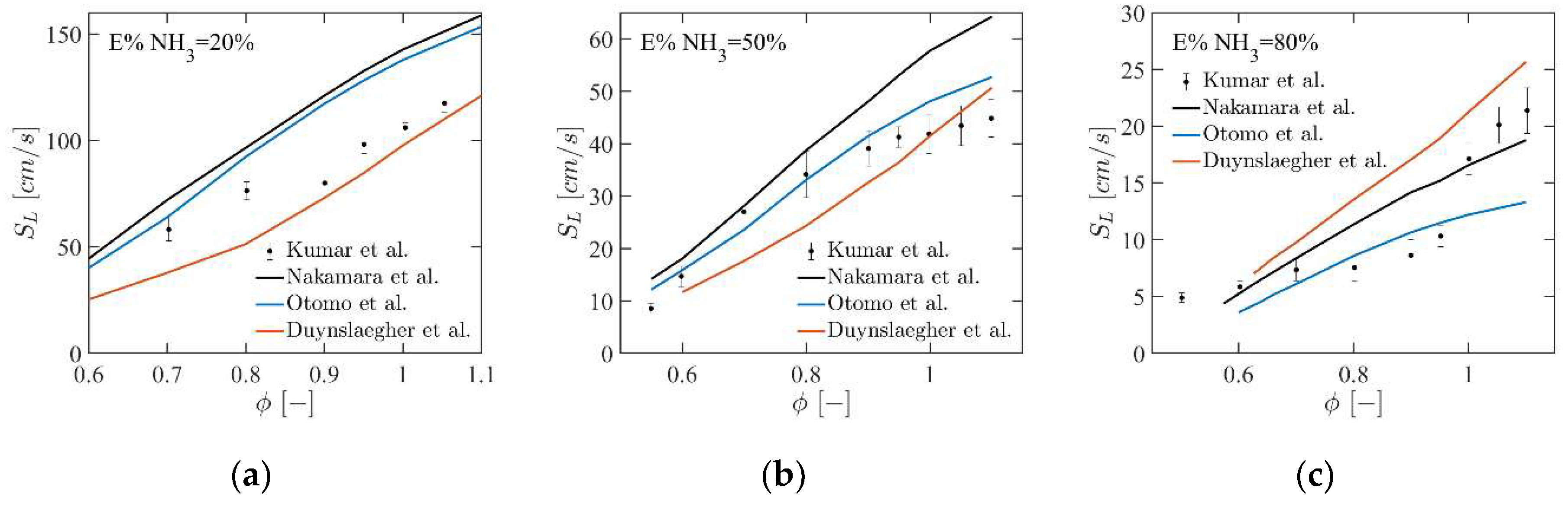
4.1. Premixed Laminar Flame Speed

Figure 4 illustrates the effects of hydrogen blending ratio and equivalence ratio on the premixed flame speed of N H 3 / H 2 blends. The flame speed increases significantly and non-linearly as more hydrogen is introduced in the blends. This behaviour can be attributed to the much higher reactivity and higher flame speed of hydrogen than ammonia. As ammonia is gradually replaced by hydrogen, the latter takes the dominant role in the oxidation reaction. However, the high hydrogen concentration in N H 3 / H 2 mixtures should be avoided, as high reactivity of hydrogen could result in boundary layer flashback [21]. Moreover, it can be observed that the flame speed increases steadily at fuel-lean conditions, reaches the peak when the equivalence ratio is around 1.1 1.2 , and then decreases at fuel-rich conditions. The premixed flame speed reaches approximately 34   c m / s when equivalence ratio and hydrogen blending ratio are 1.1 and 0.4 , respectively. Under the same conditions, the premixed flame speed of pure methane is ~ 37   c m / s [45] while the flame speed of pure hydrogen is over 200   c m / s [25]. This suggests that it is practical to apply a   N H 3 / H 2 blend with an equivalence ratio of 1.1 1.2 to realize stable combustion within the combustor.
Figure 5 demonstrates the effects of initial temperature and initial pressure on the premixed flame speed of the   N H 3 / A i r and N H 3 / H 2 / A i r   ( x % H 2 = 0.3 ) mixtures. As temperature has dominant effects on chemical reaction rate, flame speed increases rapidly with the increase in initial temperature, and the growth rate is steeper under a higher initial temperature. As the initial temperature rises from 300   K to 700   K , flame speed is increased by around 40   c m / s under atmospheric pressure. With the presence of 30 % hydrogen in fuel, the flame speed is increased by around 90   c m / s . On the contrary, flame speed is reduced as initial pressure goes up. At higher pressures, the thickness of the flame increases and the burning speed slows down. It is also notable in N H 3 / H 2 / A i r combustion that when the initial pressure increases from 1   to 5   b a r , the flame speed decreases by almost the same as the initial pressure increases from 5   to 20   b a r . This indicates that the flame speed is less sensitive to initial pressure under high pressure conditions, which is more typical under engine working conditions.
As reported, the reactions of N H 3 + H = N H 2 + H 2 , N H 3 + O H = N H 2 + H 2 O , N H 3 + O = N H 2 + O H dominate during the beginning of ammonia oxidation [44]. Mole fraction profiles of H , O , O H radicals in the flames with an equivalence ratio of 1.1 are presented in Figure 6. With the increase in hydrogen blending ratio, the concentrations of H , O , O H are all increased—in particular, the radical of H and O H . This means that the O H radical has a greater contribution to increasing the flame speed of the N H 3 / H 2 mixture. Similar behaviour is also found for fuel-lean and stoichiometric conditions [26,44].

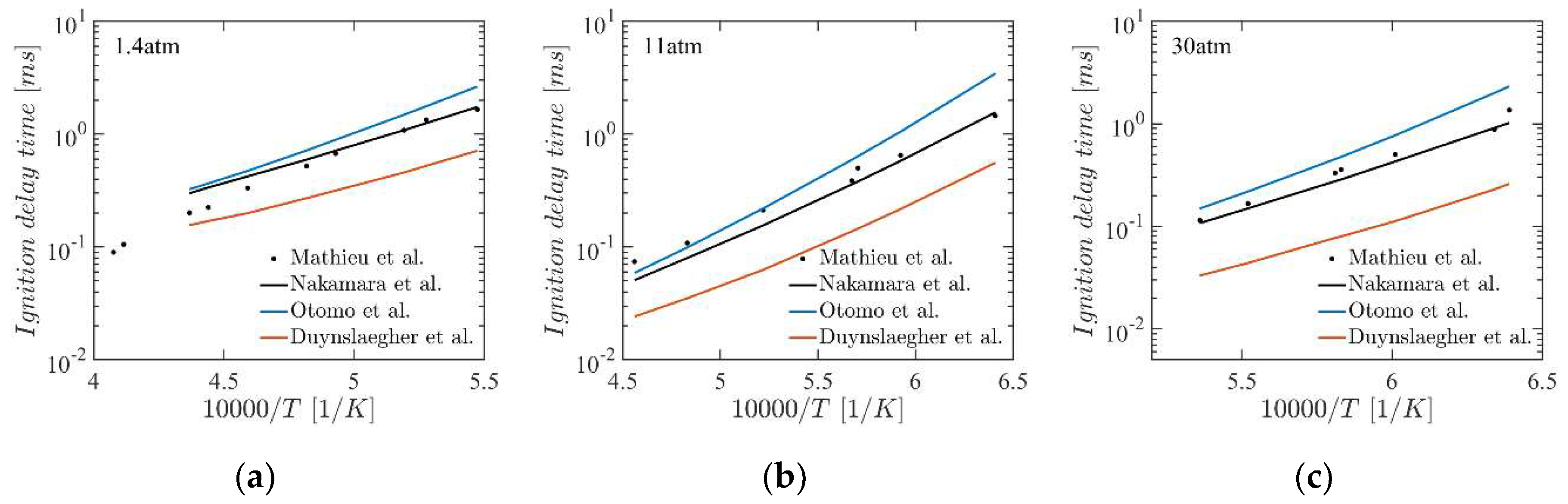
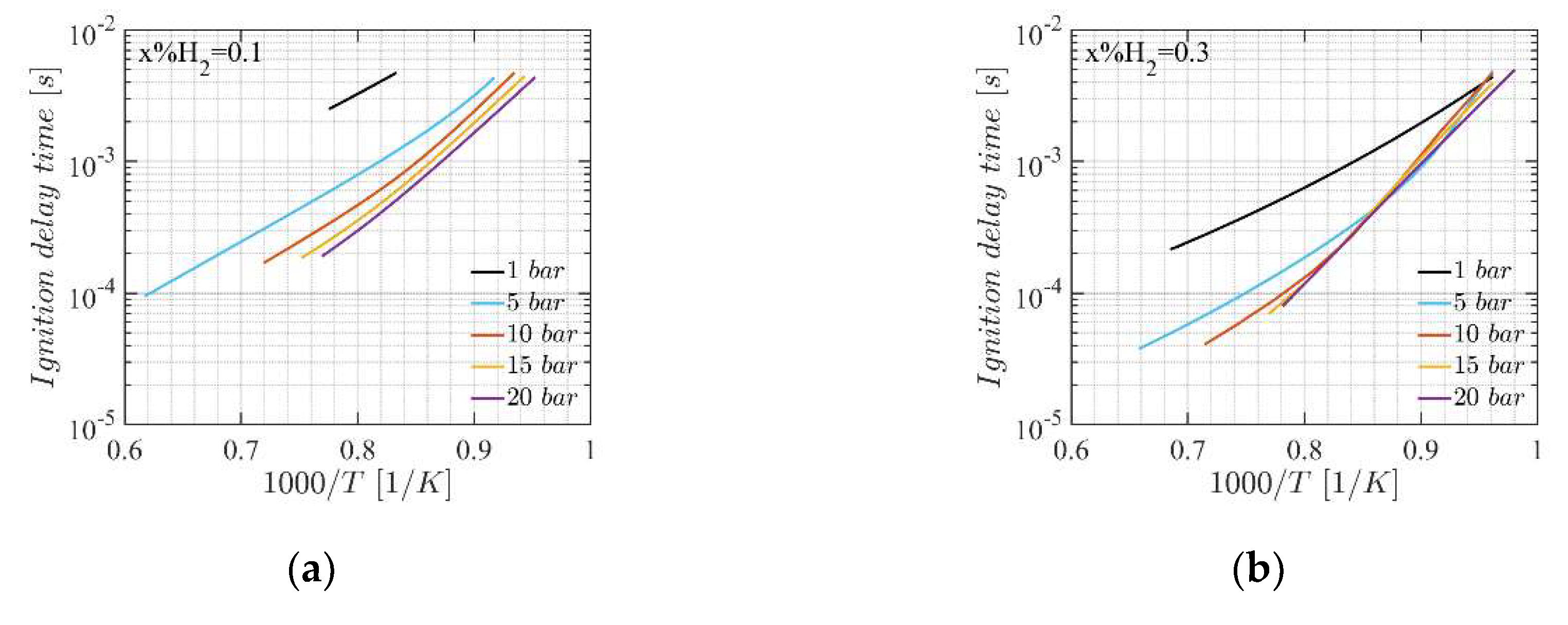
4.2. Ignition Delay Time

In Figure 7, the ignition delay time is plotted as a function of the hydrogen concentration in fuel mixtures with equivalence ratio at   0.5 , 1.0 , 1.7   and 2.0 . For a certain equivalence ratio, ignition delay time is shortened considerably with hydrogen addition. For instance, the ignition delay time drops from ~ 4 × 10 3 s to ~ 0.6 × 10 3 s as the hydrogen blending ratio reaches a value of 0.2 at stoichiometric conditions. However, there is a minor difference that can be negligible as the hydrogen blending ratio is over 0.5 . This indicates that by adding a higher reactive fuel component to ammonia, the ignition delay can be effectively shortened, which is beneficial to realize robust ignition. Similar behaviour was reported in N H 3 / C H 4 combustion [46]. Furthermore, it can be found that the influence of equivalence ratio on the ignition delay becomes weaker as more hydrogen is added to the fuel, which is also reported by Mathieu et al. [40], based on experiments of ammonia oxidation diluted by A r .
As shown in Figure 8, the influence of the initial temperature ( 1040 1620 K ) and initial pressure ( 1 20   b a r ) is discussed at the hydrogen blending ratio of 0.1 and 0.3 , respectively. The ignition delay is prolonged significantly with the decreasing initial temperature. It also can be seen that a higher initial pressure can also reduce the ignition delay time, but the reduction rate decreases with the increasing initial pressure. Take the hydrogen blending ratio of 0.3 , for instance: when the initial temperature is 1250   K   ( 1 / T = 0.8 ) , a factor ( τ 1 b a r / τ 5 b a r ) of ~ 3.13 is found between the ignition delay time under 1   and 5   b a r , while a smaller factor ( τ 5 b a r / τ 10 b a r ) of ~ 1.40 is found between 5   and 10   b a r . When the initial pressure is over 10   b a r , the ignition delay time is almost the same and the influence of initial pressure on ignition delay is negligible.

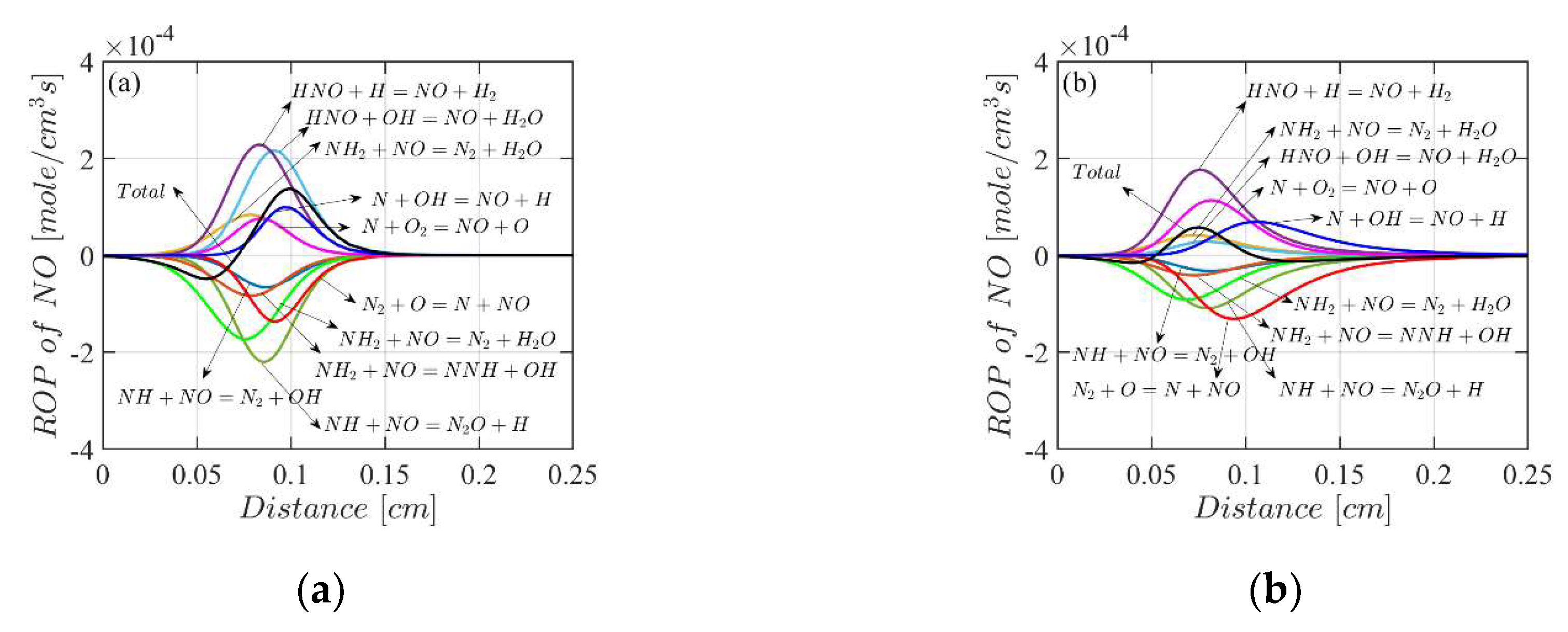
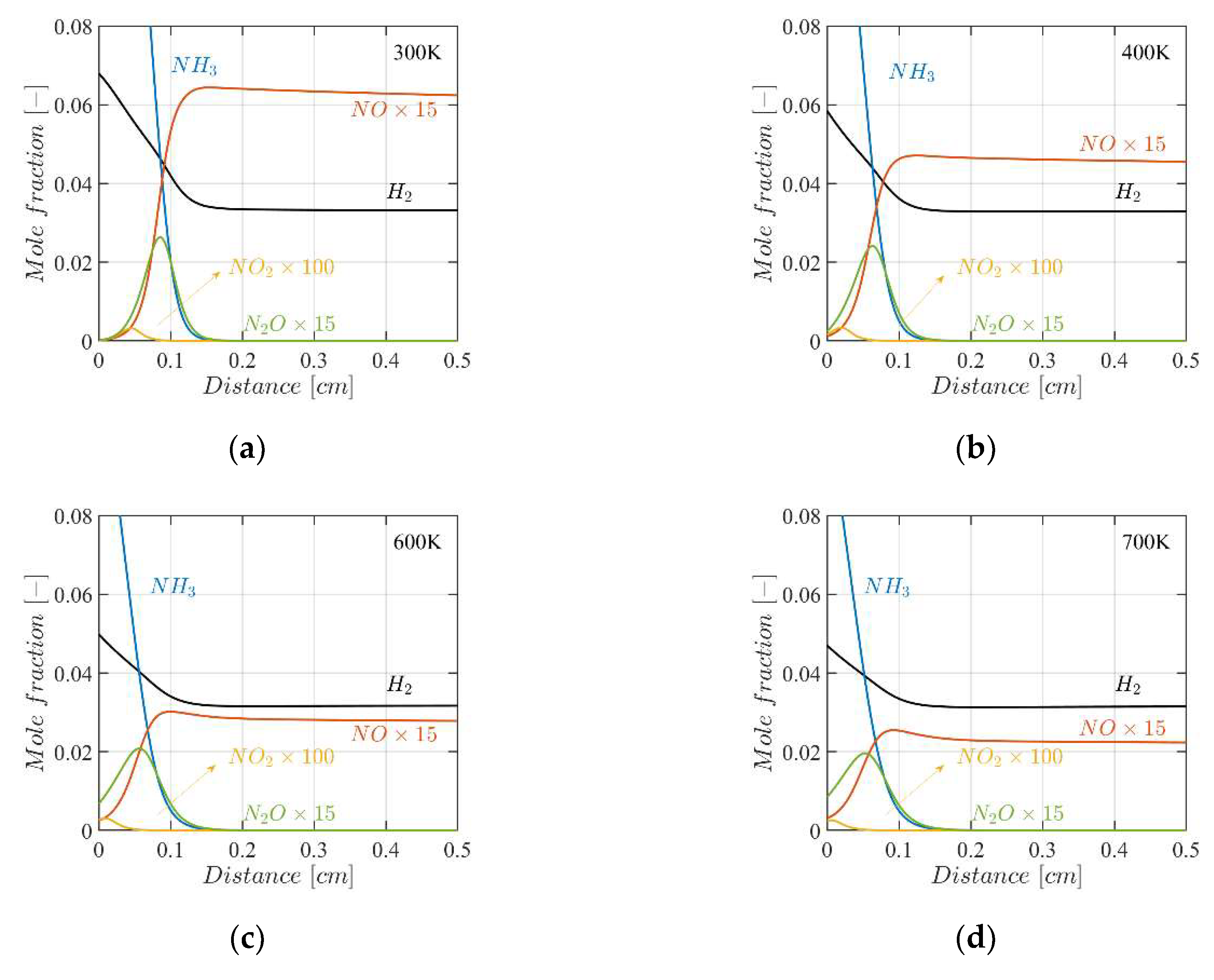
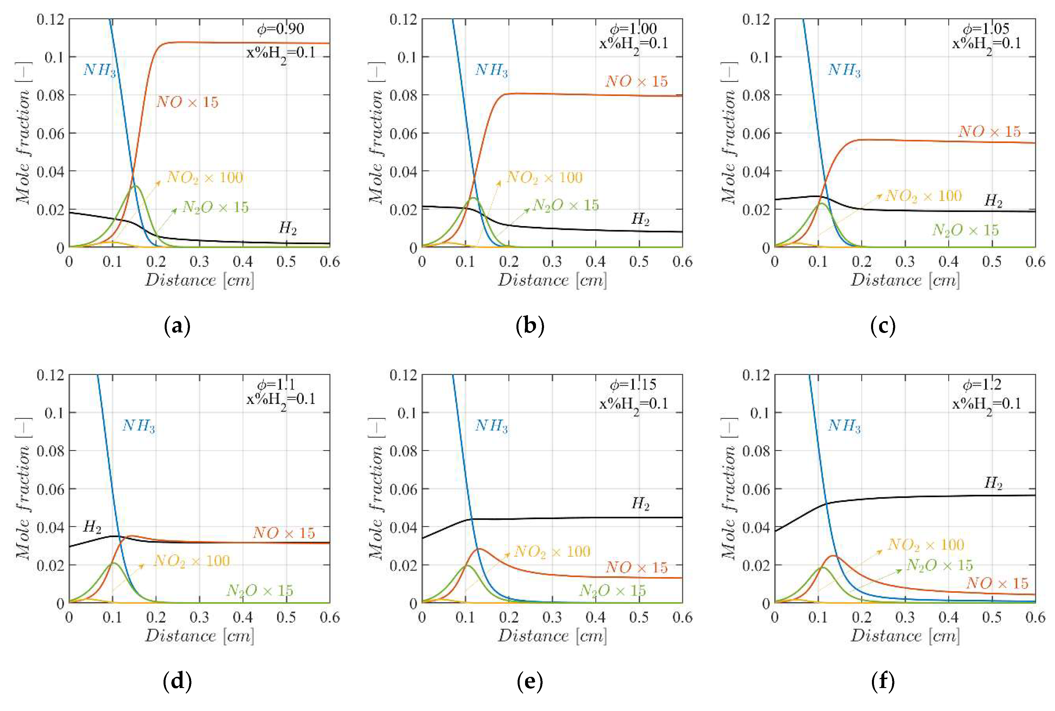
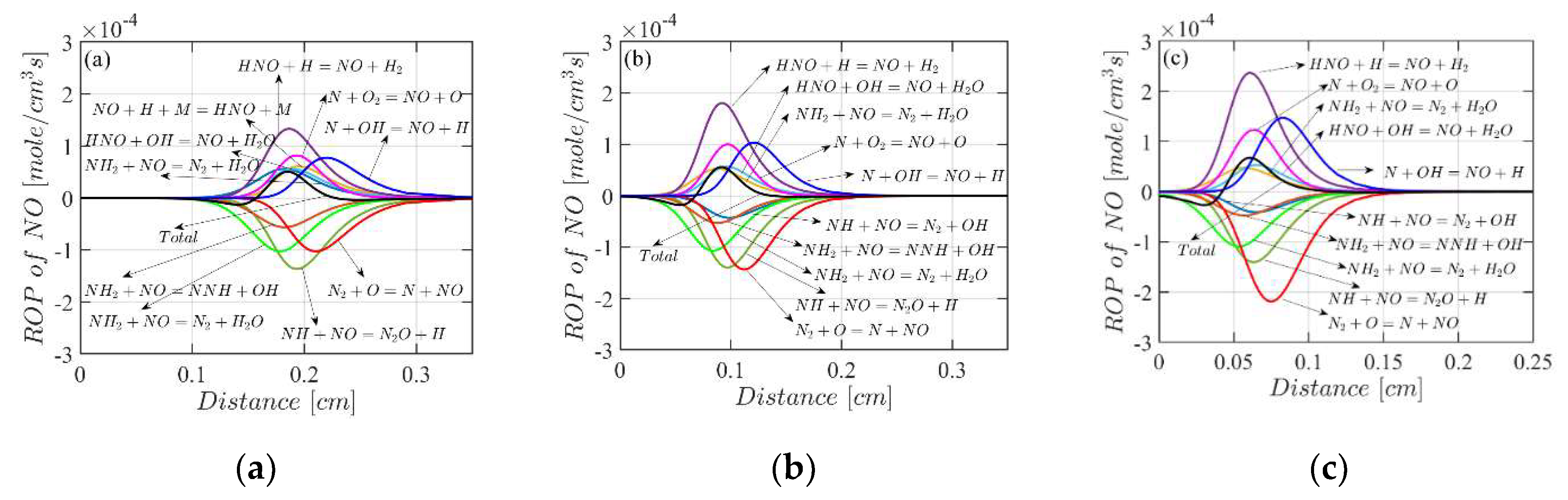
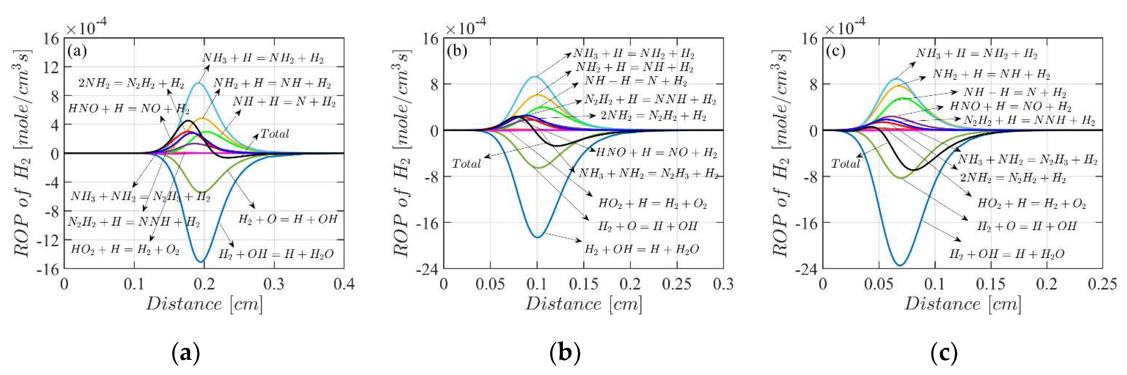
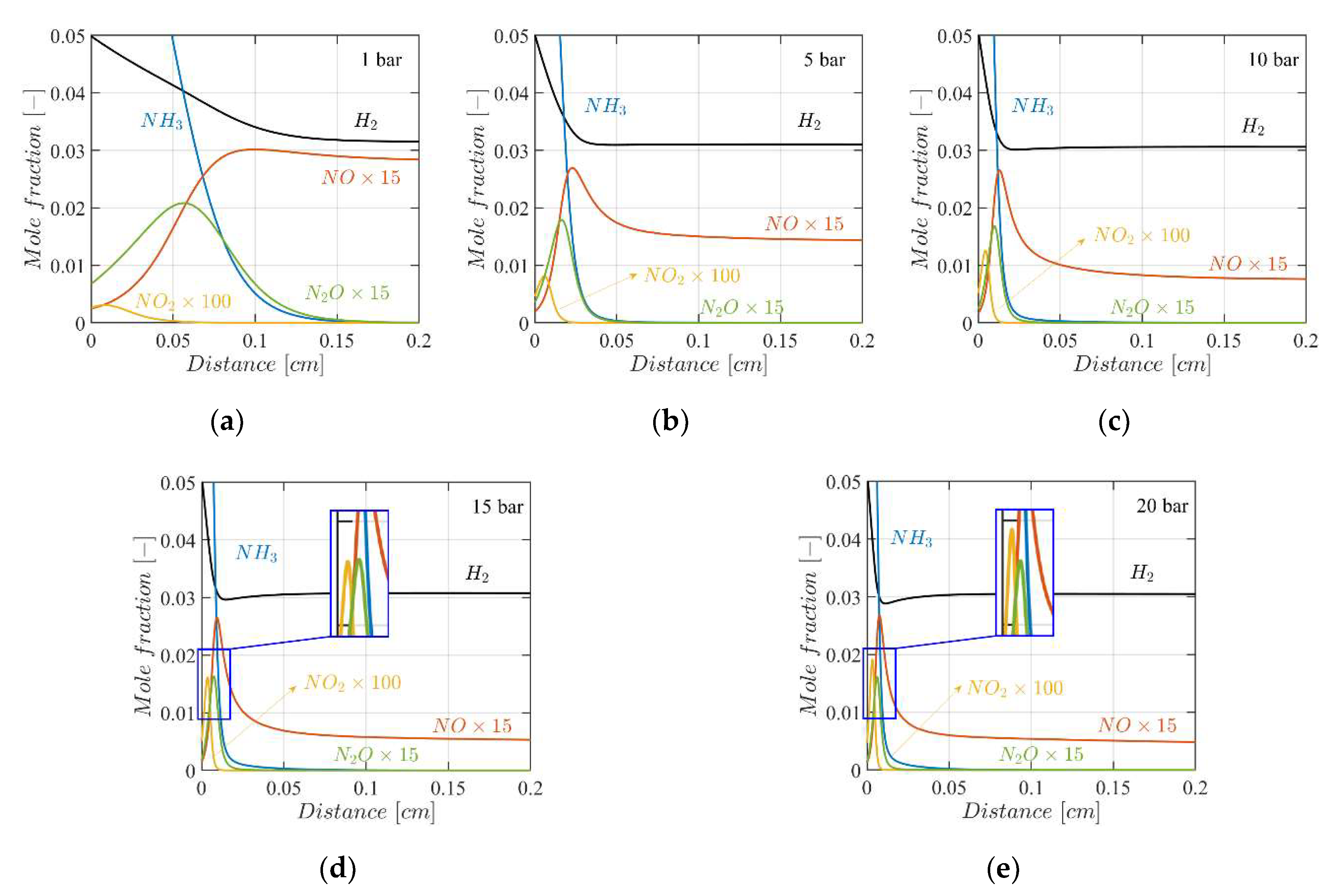
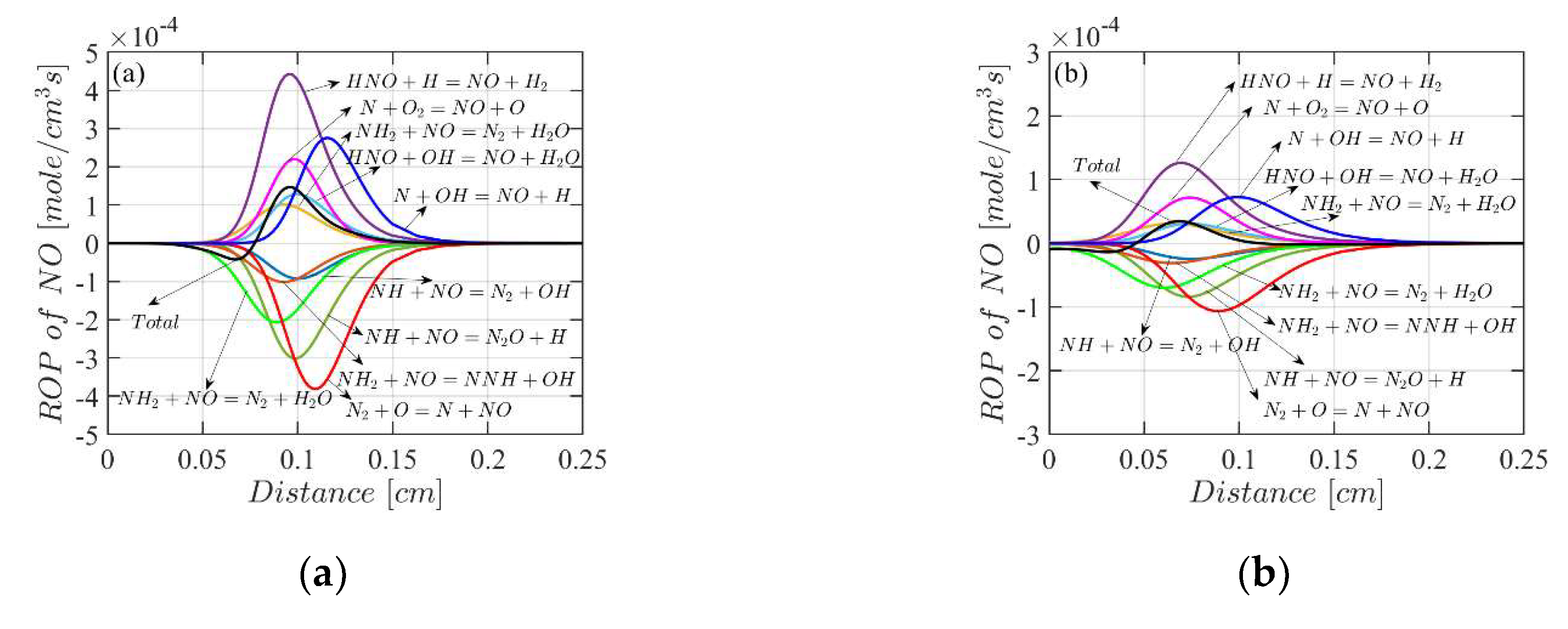
4.3. Mole Fractions of the Flame Species

As ammonia and hydrogen are zero-carbon fuels, carbon-related emissions will not be generated from ammonia/hydrogen blend combustion. However, N O x emissions become the most concerning issue as they can be produced not only through thermal N O x or Zel’dovich mechanism ( N 2 + O = N O + N , N + O 2 = N O + O , N + O H = N O + H ) , but also through fuel-bound N O x mechanism. Further insight into the N O x formation mechanism within ammonia/hydrogen combustion can be derived from premixed flame structure study based on detailed kinetic modelling, which will provide valuable information for the development of a low N O x combustion system.
In Figure 9 and Figure 10, the effects of equivalence ratio on flame species concentration are demonstrated with a hydrogen blending ratio of 0.1 and 0.3 , respectively. It can be found that N O is the dominant component of N O x emissions, while the concentrations of N O 2 and N 2 O are nearly zero in the post-flame zone. As the equivalence ratio increases, N O x emission is reduced apparently. This trend is even more explicit when the equivalence ratio is close to unity. For instance, with 10 % hydrogen in fuel, N O concentration decreases by a factor of 1.75 as ϕ increases from 1.05 to 1.10 . Additionally, it is observed that N O concentration increases rapidly before reaching a steady state under a certain equivalence ratio ( 1.10 for 10 % hydrogen in fuel and 1.15 for 30 % hydrogen in fuel), while it firstly peaks and then drops above the equivalence ratio. Besides this, the apparent increase in H 2 in the post-flame zone is noted as the flame becomes richer. Thus, an optimized equivalence ratio exists considering high N O x emissions in fuel-lean flame and high H 2 emission in fuel-rich flame.
To better understand the observed phenomena, rate of production (ROP) analysis is carried out for lean ( ϕ = 0.90 ) and rich ( ϕ = 1.20 ) flames with 30 % hydrogen in the fuel. As indicated in Figure 11, in the lean flame, N O is produced primarily through the reactions between H N O and H / O H radicals, and through the thermal- N O (Zel’dovich) mechanism reactions ( N + O 2 = N O + O and N + O H = N O + H ) to a lesser extent; the consumption of N O is mainly through N H i + N O reactions, and through the reverse reaction of the rate-limiting step of thermal- N O mechanism ( N 2 + O = N O + N ) to a lesser extent. In the rich flame, the contribution from H N O + O H to N O production reduces, while that from N + O 2 increases; the dominant role of the reverse thermal- N O mechanism ( N 2 + O = N O + N ) in N O reduction is noted and should be relevant to the drop in N O concentration in rich flames. As reported by Kobayashi [9], when the flame becomes richer, concentrations of O / H / O H radicals drop, which tends to inhibit N O formation from N H i oxidation via H N O . Meanwhile, the relative concentration of H in radical pool rises in rich flame, which promotes the reactions between N H i and H . As a result, abundant H 2 and N will be produced. The existence of more nitrogen atoms will promote the reactions of the aforementioned thermal- N O (Zel’dovich) mechanism, which aligns with the findings of ROP analysis.
Figure 12 shows the flame structure under various hydrogen blending ratios in fuel, with equivalence ratio, initial temperature and pressure kept constant. With more hydrogen addition, N O concentration in the post-flame zone only shows a marginal increase. Despite the higher initial H 2 concentration in the high-hydrogen-ratio flame, the steady state H 2 concentration almost remains unchanged. Although the total rate of N O production should share similar behaviour to N O mole fraction, the contribution from certain reactions changes with the H 2 blending ratio. As shown in Figure 13, both the thermal N O mechanism and fuel-bound N O mechanism are active for N O production and reduction. However, the contribution from the thermal N O mechanism ( N + O H for N O production and N + N O for N O reduction) increases as more H 2 is added into the fuel. The unchanged H 2   concentration in the post-flame zone can be attributed to the promoted H 2 consumption rate through the reaction between H 2 and O H radical when H 2 is added into the fuel, as indicated by Figure 14.
The effects of the initial temperature range of 300 700   K and the initial pressure range of 1 20   b a r on flame structure are demonstrated in Figure 15 and Figure 16, respectively. The hydrogen concentration in the fuel mixtures is set to 0.3 , and the equivalence ratio is set to 1.10 . The effect of the initial temperature is investigated at atmospheric pressure. Figure 15 indicates that N O concentration in the post-flame zone decreases from 9.6 × 10 8 to 4.61 × 10 8   as the initial temperature rises from 300 to 700   K , although the increase in initial temperature is usually expected to promote the thermal N O x formation. In a modelling study of a stoichiometric N H 3   ( 60 % ) /   C H 4   ( 40 % ) premixed flame by Xiao [46], N O x   emissions were found to rise with the increase in initial temperature. The unexpected reduction of N O under high initial temperature condition can be explained based on the ROP analysis shown in Figure 17. In a lower inlet temperature, fuel-bound N O is dominant in the production of nitric oxide, while thermal- N O contributes less; the reverse thermal- N O reaction is dominant in the consumption of nitric oxide, while the combination with N H i contributes less. The same behavior is also found in the case with a higher inlet temperature, but the rate of both production and consumption is decreased, which could be the reason for the reduction in N O emission.
The influence of initial pressure on N H 3 / H 2 flames is studied, with the equivalence ratio, initial temperature and hydrogen blending ratio kept at 1.10 , 600   K and 0.3 , respectively. As shown in Figure 16, N O is reduced significantly as pressure increases, which agrees with the phenomena reported by other works [9]. This trend can be attributed to the consumption of N H i species via the promoted radical combination reactions under high pressure conditions [9]. It suggests that low N O x emission is possible under high pressure conditions, which is practical for engine application. In addition, it is noticeable that the peak in N O 2 concentration in the reaction zone is increased at higher initial pressure.

5. Conclusions

To support the development of a novel linear engine generator (LEG), the characteristics of ammonia/hydrogen premixed combustion are studied by using a detailed chemical kinetics mechanism, which is selected among several mechanisms based on validation against the same sets of experimental data.
Extensive parametric analysis is carried out under LEG typical working conditions to study the effects of equivalence ratio ( 0.80 1.60 ) , hydrogen blending ratio ( 0.0 0.6 ) , initial temperature ( 300 700   K )   and initial pressure ( 1 20   b a r ) on premixed laminar flame speed, ignition delay and key flame species concentrations.
It is shown that an optimized equivalence ratio exists around 1.10 1.20   for N H 3 / H 2 premixed flames to realize stable and efficient combustion as well as low N O x emission. Ignition delay is reduced with the increase in hydrogen blending ratio, initial temperature and initial pressure. At a certain initial temperature and initial pressure, the effects of hydrogen blending ratio can be negligible for over 50 % hydrogen in the fuel. Under higher pressure ( > 10   b a r ), the initial pressure has a minor influence on the ignition delay reduction. It is also found that the high-pressure, high-temperature environment is favourable for low N O x emission from ammonia/hydrogen combustion, which implies the potential for a low N O x LEG fuelled by ammonia/hydrogen.

Funding

This research was funded by EPSRC, grant number EP/S00193X/1.

Acknowledgments

The authors appreciate the support from EPSRC (Engineering and Physical Sciences Research Council, United Kingdom) on the project, Powering Carbon-free Autonomous Shipping: Ammonia/Hydrogen dual-fuelled Linear Engine-Generator (EP/S00193X/1).

Conflicts of Interest

The authors declare no conflict of interest.

References

  1. Mikalsen, R.; Roskilly, A.P. A review of free-piston engine history and applications. Appl. Therm. Eng. 2007, 27, 2339–2352. [Google Scholar] [CrossRef]
  2. Hung, N.B.; Lim, O. A review of free-piston linear engines. Appl. Energy 2016, 178, 78–97. [Google Scholar] [CrossRef]
  3. Schneider, S.; Chiodi, M.; Friedrich, H.; Bargende, M. Development and Experimental Investigation of a Two-Stroke Opposed-Piston Free-Piston Engine. SAE Tech. Pap. 2016, 1, 16. [Google Scholar] [CrossRef]
  4. Johnson, T.A.; Leick, M.T.; Moses, R.W. Experimental Evaluation of a Prototype Free Piston Engine—Linear Alternator (FPLA) System. SAE Tech. Pap. 2016, 1, 12. [Google Scholar] [CrossRef]
  5. Kosaka, H.; Akita, T.; Moriya, K.; Goto, S.; Hotta, Y.; Umeno, T.; Nakakita, K. Development of Free Piston Engine Linear Generator System Part 1—Investigation of Fundamental Characteristics. SAE Tech. Pap. 2014, 1, 8. [Google Scholar] [CrossRef]
  6. Goto, S.; Moriya, K.; Kosaka, H.; Akita, T.; Hotta, Y.; Umeno, T.; Nakakita, K. Development of Free Piston Engine Linear Generator System Part 2—Investigation of Control System for Generator. SAE Tech. Pap. 2014, 1, 8. [Google Scholar] [CrossRef]
  7. Mikalsen, R.; Roskilly, A.P. The free-piston reciprocating Joule Cycle engine: A new approach to efficient domestic CHP generation. In Proceeding of ICAE2012 Conference; 2012; Applied Energy: Suzhou, China, 2012. [Google Scholar]
  8. Jia, B.; Wu, D.; Smallbone, A.; Ngwaka, U.C.; Roskilly, A.P. Dynamic and thermodynamic characteristics of a linear Joule engine generator with different operating conditions. Energy Convers. Manag. 2018, 173, 375–382. [Google Scholar] [CrossRef]
  9. Kobayashi, H.; Hayakawa, A.; Somarathne, K.D.K.A.; Okafor, E.C. Science and technology of ammonia combustion. Proc. Combust. Inst. 2019, 37, 109–133. [Google Scholar] [CrossRef]
  10. SIP energy carriers 2016. Available online: http://www.jst.go.jp/sip/pdf/SIP_energycarriers2016_en.pdf (accessed on 14 May 2020).
  11. Aziz, M.; Wijayanta, A.T.; Nandiyanto, A.B.D. Ammonia as Effective Hydrogen Storage: A Review on Production, Storage and Utilization. Energies 2020, 13, 3062. [Google Scholar] [CrossRef]
  12. Crolius, S.H. NH3 Energy Implementation Conference: A Brief Report. Available online: https://www.ammoniaenergy.org/articles/nh3-energy-implementation-conference-a-brief-report/ (accessed on 8 July 2020).
  13. Kojima, Y.; Miyaoka, H.; Ichikawa, T. Ammonia-Based Hydrogen Storage Materials. In Advanced Materials for Clean Energy; CRC Press: Boca Raton, FL, USA, 2015; pp. 497–526. [Google Scholar] [CrossRef]
  14. Sanchez Garcia, A.; Martín, M. Optimal renewable production of ammonia from water and air. J. Clean. Prod. 2018, 178, 325–342. [Google Scholar] [CrossRef]
  15. Frigo, S.; Gentili, R. Analysis of the behaviour of a 4-stroke Si engine fuelled with ammonia and hydrogen. Int. J. Hydrog. Energy 2013, 38, 1607–1615. [Google Scholar] [CrossRef]
  16. Ryu, K.; Zacharakis-Jutz, G.E.; Kong, S.-C. Performance characteristics of compression-ignition engine using high concentration of ammonia mixed with dimethyl ether. Appl. Energy 2014, 113, 488–499. [Google Scholar] [CrossRef]
  17. Kurata, O.; Iki, N.; Matsunuma, T.; Inoue, T.; Tsujimura, T.; Furutani, H.; Kobayashi, H.; Hayakawa, A. Performances and emission characteristics of NH3–air and NH3CH4–air combustion gas-turbine power generations. Proc. Combust. Inst. 2017, 36, 3351–3359. [Google Scholar] [CrossRef]
  18. Xiao, H.; Valera-Medina, A.; Bowen, P.J. Modeling Combustion of Ammonia/Hydrogen Fuel Blends under Gas Turbine Conditions. Energy Fuels 2017, 31, 8631–8642. [Google Scholar] [CrossRef]
  19. Hayakawa, A.; Arakawa, Y.; Mimoto, R.; Somarathne, K.D.K.A.; Kudo, T.; Kobayashi, H. Experimental investigation of stabilization and emission characteristics of ammonia/air premixed flames in a swirl combustor. Int. J. Hydrog. Energy 2017, 42, 14010–14018. [Google Scholar] [CrossRef]
  20. Okafor, E.C.; Naito, Y.; Colson, S.; Ichikawa, A.; Kudo, T.; Hayakawa, A.; Kobayashi, H. Measurement and modelling of the laminar burning velocity of methane-ammonia-air flames at high pressures using a reduced reaction mechanism. Combust. Flame 2019, 204, 162–175. [Google Scholar] [CrossRef]
  21. Valera-Medina, A.; Pugh, D.G.; Marsh, P.; Bulat, G.; Bowen, P. Preliminary study on lean premixed combustion of ammonia-hydrogen for swirling gas turbine combustors. Int. J. Hydrog. Energy 2017, 42, 24495–24503. [Google Scholar] [CrossRef]
  22. Hiroyuki, T.; Jun, H.; Shota, K.; Kimio, I.; Fumiteru, A. Characteristics of ammonia/N2/O2 laminar flame in oxygen-enriched air condition. Trans. JSME 2015, 81, 14–00423. [Google Scholar]
  23. Irvin, G.; Richard, A.Y.; Nick, G.G. Combustion, 5th ed.; Academic Press: Cambridge, MA, USA, 2014. [Google Scholar] [CrossRef]
  24. Li, J.; Huang, H.; Kobayashi, N.; He, Z.; Nagai, Y. Study on using hydrogen and ammonia as fuels: Combustion characteristics and NOx formation. Int. J. Energy Res. 2014, 38, 1214–1223. [Google Scholar] [CrossRef]
  25. Ichikawa, A.; Hayakawa, A.; Kitagawa, Y.; Kunkuma Amila Somarathne, K.D.; Kudo, T.; Kobayashi, H. Laminar burning velocity and Markstein length of ammonia/hydrogen/air premixed flames at elevated pressures. Int. J. Hydrog. Energy 2015, 40, 9570–9578. [Google Scholar] [CrossRef]
  26. Nozari, H.; Karabeyoğlu, A. Numerical study of combustion characteristics of ammonia as a renewable fuel and establishment of reduced reaction mechanisms. Fuel 2015, 159, 223–233. [Google Scholar] [CrossRef]
  27. Vigueras-Zuniga, M.-O.; Tejeda-del-Cueto, M.-E.; Vasquez-Santacruz, J.-A.; Herrera-May, A.-L.; Valera-Medina, A. Numerical Predictions of a Swirl Combustor Using Complex Chemistry Fueled with Ammonia/Hydrogen Blends. Energies 2020, 13, 288. [Google Scholar] [CrossRef]
  28. Miller, J.A.; Bowman, C.T. Mechanism and modeling of nitrogen chemistry in combustion. Prog. Energy Combust. Sci. 1989, 15, 287–338. [Google Scholar] [CrossRef]
  29. Klippenstein, S.J.; Harding, L.B.; Glarborg, P.; Miller, J.A. The role of NNH in NO formation and control. Combust. Flame 2011, 158, 774–789. [Google Scholar] [CrossRef]
  30. Song, Y.; Hashemi, H.; Christensen, J.M.; Zou, C.; Marshall, P.; Glarborg, P. Ammonia oxidation at high pressure and intermediate temperatures. Fuel 2016, 181, 358–365. [Google Scholar] [CrossRef]
  31. Otomo, J.; Koshi, M.; Mitsumori, T.; Iwasaki, H.; Yamada, K. Chemical kinetic modeling of ammonia oxidation with improved reaction mechanism for ammonia/air and ammonia/hydrogen/air combustion. Int. J. Hydrog. Energy 2018, 43, 3004–3014. [Google Scholar] [CrossRef]
  32. Konnov, A.A. Implementation of the NCN pathway of prompt-NO formation in the detailed reaction mechanism. Combust. Flame 2009, 156, 2093–2105. [Google Scholar] [CrossRef]
  33. Meyer, T.; Kumar, P.; Li, M.; Redfern, K.; Diaz, D. Ammonia Combustion with Near-zero Pollutant Emissions. In NH3 Congress: Iowa, USA; Iowa State University: Ames, IA, USA, 2011. [Google Scholar]
  34. Duynslaegher, C.; Contino, F.; Vandooren, J.; Jeanmart, H. Modeling of ammonia combustion at low pressure. Combust. Flame 2012, 159, 2799–2805. [Google Scholar] [CrossRef]
  35. Duynslaegher, C.; Jeanmart, H.; Vandooren, J. Flame structure studies of premixed ammonia/hydrogen/oxygen/argon flames: Experimental and numerical investigation. Proc. Combust. Inst. 2009, 32, 1277–1284. [Google Scholar] [CrossRef]
  36. Gregory, P.S.; David, M.G.; Michael, F.; Nigel, W.M.; Boris, E.; Mikhail, G.; Ronald, K.H.; Soonho, S.; William, C.G. GRI-Mech 3.0. Available online: http://www.me.berkeley.edu/gri_mech/ (accessed on 14 May 2020).
  37. Mechanical and Aerospace Engineering (Combustion Research), U.o.C.a.S.D. Chemical-Kinetic Mechanisms for Combustion Applications. Available online: http://combustion.ucsd.edu (accessed on 14 May 2020).
  38. Lindstedt, R.P.; Lockwood, F.C.; Selim, M.A. Detailed Kinetic Modelling of Chemistry and Temperature Effects on Ammonia Oxidation. Combust. Sci. Technol. 1994, 99, 253–276. [Google Scholar] [CrossRef]
  39. Jiang, B. Mécanisme de Formation et de Disparition des Oxydes D’azote dans les Flammes: Étude Expérimentale et Modélisation. Ph.D. Thesis, Université Catholique de Louvain, Ottignies-Louvain-la-Neuve, Belgium, 1990. [Google Scholar]
  40. Mathieu, O.; Petersen, E.L. Experimental and modeling study on the high-temperature oxidation of Ammonia and related NOx chemistry. Combust. Flame 2015, 162, 554–570. [Google Scholar] [CrossRef]
  41. Bugler, J.; Somers, K.P.; Simmie, J.M.; Güthe, F.; Curran, H.J. Modeling Nitrogen Species as Pollutants: Thermochemical Influences. J. Phys. Chem. A 2016, 120, 7192–7197. [Google Scholar] [CrossRef] [PubMed]
  42. Nakamura, H.; Hasegawa, S.; Tezuka, T. Kinetic modeling of ammonia/air weak flames in a micro flow reactor with a controlled temperature profile. Combust. Flame 2017, 185, 16–27. [Google Scholar] [CrossRef]
  43. ANSYS CHEMKIN PRO Version 17.0. Available online: http://www.ansys.com/products/fluids/ansys-chemkin-proANSYS (accessed on 10 March 2016).
  44. Kumar, P.; Meyer, T.R. Experimental and modeling study of chemical-kinetics mechanisms for H2–NH3–air mixtures in laminar premixed jet flames. Fuel 2013, 108, 166–176. [Google Scholar] [CrossRef]
  45. Okafor, E.C.; Naito, Y.; Colson, S.; Ichikawa, A.; Kudo, T.; Hayakawa, A.; Kobayashi, H. Experimental and numerical study of the laminar burning velocity of CH4–NH3–air premixed flames. Combust. Flame 2018, 187, 185–198. [Google Scholar] [CrossRef]
  46. Xiao, H.; Valera-Medina, A.; Bowen, P.J. Study on premixed combustion characteristics of co-firing ammonia/methane fuels. Energy 2017, 140, 125–135. [Google Scholar] [CrossRef]
Figure 1. Comparison between experimental and computational premixed N H 3 / H 2 laminar flame speed when E % N H 3   is (a) 20 % , (b) 50 % and (c) 80 % . Experimental results by Kumar et al. [44] plotted in conjunction with computational results using Nakamura’s mechanism [42], Otomo’s mechanism [31] and Duynslaegher’s reduced mechanism [34].
Proceedings 58 00002 g001
Figure 2. Comparison between experimental and computational ignition delay time for the case of 0.01143 N H 3 / 0.00857 O 2 / 0.98 A r ( ϕ = 1.0 ) at (a) 1.4   a t m , (b) 11   a t m and (c) 30   a t m . Experimental results by Mathieu et al. [40] plotted in conjunction with computational results using Nakamura’s mechanism, Otomo’s mechanism and Duynslaegher’s reduced mechanism.
Proceedings 58 00002 g002
Figure 3. Comparison between experimental and computational concentration profiles of (a) N O , N H 2 ,     N 2 O and (b) N H 3 ,   H 2 , N 2 for the case of 0.21 N H 3 / 0.13 H 2 / 0.21 O 2 / 0.45 A r at 0.05   b a r . Experimental results by Duynslaegher et al. [35] plotted in conjunction with computational results using Nakamura’s mechanism, Otomo’s mechanism and Duynslaegher’s reduced mechanism.
Proceedings 58 00002 g003
Figure 4. Flame speed as a function of equivalence ratio in various hydrogen fractions at initial temperature of 300   K and pressure of 1   b a r .
Proceedings 58 00002 g004
Figure 5. Premixed N H 3 / H 2 / A i r flame speed as a function of initial temperature under 1 , 5 , 10 , 15 , 20   b a r   (   ϕ = 1.10 ).
Proceedings 58 00002 g005
Figure 6. Radicals profiles of O ,     H ,     O H with hydrogen blending ratio at (a) 0.0 , (b) 0.2 , (c) 0.4 and (d) 0.6   ( ϕ = 1.10 ) .
Proceedings 58 00002 g006
Figure 7. Ignition delay time as a function of hydrogen blending ratio for various equivalence ratios at initial temperature of 1400   K and pressure of 1   b a r .
Proceedings 58 00002 g007
Figure 8. Ignition delay time as a function of 1000 / T under the initial pressure of 1 20   b a r at the hydrogen blending ratio of (a) 0.1 and (b) 0.3   ( ϕ = 1.10 ) .
Proceedings 58 00002 g008
Figure 9. Species profiles of N H 3 ,     H 2 , N O , N O 2 ,     N 2 O at (a) ϕ = 0.90 , (b) ϕ = 1.00 , (c) ϕ = 1.05 , (d) ϕ = 1.10 , (e) ϕ = 1.15 and (f) ϕ = 1.20 under initial temperature of 500   K and pressure of 1   b a r for hydrogen blending ratio of 0.1 .
Proceedings 58 00002 g009
Figure 10. Species profiles of N H 3 , H 2 , N O , N O 2 ,     N 2 O at (a) ϕ = 0.90 , (b) ϕ = 1.00 , (c) ϕ = 1.05 , (d) ϕ = 1.10 , (e) ϕ = 1.15 and (f) ϕ = 1.20 under initial temperature of 500   K and pressure of 1   b a r for hydrogen blending ratio of 0.3 .
Proceedings 58 00002 g010
Figure 11. Rate of production of N O at (a) ϕ = 0.90 and (b) = 1.20   ( x % H 2 = 0.3 ) .
Proceedings 58 00002 g011
Figure 12. Species profiles of N H 3 ,     H 2 , N O , N O 2 , N 2 O at the hydrogen blending ratio of (a) 0.0 , (b) 0.04 , (c) 0.1 , (d) 0.2 , (e) 0.5 and (f) 0.8 under initial temperature of 500   K and pressure of 1   b a r for equivalence ratio of 1.10 .
Proceedings 58 00002 g012
Figure 13. Rate of production of N O at (a) x % H 2 = 0.0 , (b) x % H 2 = 0.2 and (c) x % H 2 = 0.5 .
Proceedings 58 00002 g013
Figure 14. Rate of production of H 2 at (a) x % H 2 = 0.0 , (b) x % H 2 = 0.2 and (c) x % H 2 = 0.5 .
Proceedings 58 00002 g014
Figure 15. Species profiles of N H 3 ,     H 2 , N O , N O 2 ,     N 2 O under the initial temperature of (a) 300   K , (b) 400   K , (c) 600   K and (d) 700   K at atmospheric pressure ( ϕ = 1.10 ).
Proceedings 58 00002 g015
Figure 16. Species profiles of N H 3 ,     H 2 , N O , N O 2 , N 2 O under (a) 1   b a r , (b) 5   b a r , (c) 10   b a r , (d) 15   b a r and (e) 20   b a r at the initial temperature of 600   K ( ϕ = 1.10 ).
Proceedings 58 00002 g016
Figure 17. Rate of production of N O at the inlet temperature of (a) 300   K and (b) 700   K .
Proceedings 58 00002 g017
Publisher’s Note: MDPI stays neutral with regard to jurisdictional claims in published maps and institutional affiliations.

