Abstract
Standing wave interferometers (SWIs) show enormous potential for miniaturization because of their simple linear optical set-up, consisting only of a laser source, a measuring mirror and two standing wave sensors for obtaining quadrature signals. To reduce optical influences on the standing wave and avoid the need for an exact and long-term stable sensor-to-sensor distance, a single-sensor set-up was developed with a phase modulation by forced oscillation of the measuring mirror. When the correct modulation stroke is applied, the harmonics in the sensor signal can be used for obtaining quadrature signals for phase demodulation and direction discrimination.
1. Introduction
Laser interferometers for high-precision length measurements in industry and precision engineering have been beneficially used for decades. In contrast to the complex set-up and the need for elaborate adjustment of commercial Michelson-type interferometers, standing wave interferometers (SWIs) offer a simple linear structure with only a small amount of components [1,2]. In this paper, an approach is presented which requires only a transparent photo sensor, a single laser source and a simple ultrasonic transducer to build up a complete interferometer.
2. Detection of an Optical Standing Wave
When an optical wave is reflected at a mirror, the incident and reflected beam interfere, forming a standing wave. It can be shown that the intensity is coupled to the mirror surface so that moving the mirror along the optical axis will also shift the periodic profile. The standing wave can be detected by a thin transparent photo sensor [3], which is inserted in the optical path and has a photo active area of 1 mm × 1 mm, which matches approx. the diameter of the laser beam. The overall size of the die is 5 mm × 7 mm; for proper handling, it is bonded on a printed circuit board (see Figure 1).
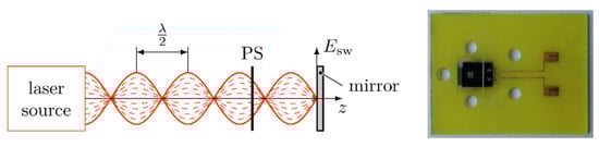
Figure 1.
(Left) electrical field intensity of a standing wave and detection by a transparent photo sensor (PS, right). at the mirror surface at all times. Dashed lines indicate the time dependency of .
When there is a relative movement between the sensor and the mirror, the minima and maxima of will shift through PS. From the optical signal, it is possible to determine the moving distance by counting the minima and maxima, assuming is known.
3. Quadrature Signal Generation
The approach in this project uses a phase-modulated sensor signal to obtain the quadrature signals for direction discrimination. When the position of the measuring mirror is modulated with a frequency , harmonics occur in the sensor signal, alternatingly sin- and cos-associated to the carrier signal. Figure 2 shows a part of the resulting spectrum. To obtain quadrature signals from the modulated sensor signal , it is necessary to extract at least two spectral components: one sin- and one cos-component. In our project, this is achieved by using a lock-in-technique. As both quadrature signals are located in the base band after mixing and filtering, it is possible to use the standard arctan-demodulation procedure afterwards for determination of the sensor signal phase.
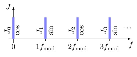
Figure 2.
Resulting spectrum of the sensor signal with a modulated measuring mirror and a modulation frequency .
4. Experimental Set-Up and Results
The experimental set-up is as simple as shown in Figure 3. The whole interferometer consists of a fibre-coupled He-Ne laser, a modulated measuring mirror and the transparent standing wave. sensor.
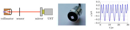
Figure 3.
Experimental set-up for the phase-modulated standing wave interferometer (left). The measuring mirror is modulated by an ultrasonic transducer (UST, middle), applying the correct stroke to obtain quadrature signals. Moving either the sensor or the mirror along the optical axis will result in an alternating sensor signal , suitable for length measurements (right).
The UST was mounted on an additional piezo actuator (cascaded driving system), where the voltage applied was increased and decreased stepwise. This results in a staggered motion of the mirror, superimposed by the forced oscillation. Measurements of large moving distances with high velocities could be shown with the standing wave sensor mounted on a motorised linear axis with a positioning range of 100 mm. The generation of the modulation signal for the UST as well as the signal processing of the modulated sensor signal was performed by an FPGA-based test and measuring board.
Author Contributions
Conceptualization: E.M., I.W.R.; methodology: I.O., J.-P.Z.; investigation: J.-P.Z., I.O.; writing—original draft preparation: I.O.; writing—review and editing: E.M., I.W.R.; supervision: E.M., I.W.R. All authors have read and agreed to the published version of the manuscript.
Funding
The project was funded by the German Federal Ministry of Education and Research under contract 03V0235.
Conflicts of Interest
The authors declare no conflict of interest.
References
- Büchner, H. Stehende-Wellen-Interferometer zur Messung von Optischen Gangunterschieden. Deutsches Patent DE 3300369 C2, 19 June 1987. [Google Scholar]
- Ortlepp, I.; Büchner, H.-J.; Ivanov, T.; Hofer, M.; Zöllner, J.P.; Rangelow, I.; Manske, E. Miniatur-Stehende-Welle-Interferometer auf Basis schneller, transparenter Photodioden 18. GMA/ITG-Fachtag. Sens. Messsyst. 2016, 49, 418–424. [Google Scholar]
- Ortlepp, I.; Büchner, H.-J.; Ivanov, T.; Hofer, M.; Zöllner, J.P.; Rangelow, I.; Manske, E. Ultrathin transparent photodetector for use in Standing-Wave Interferometer. In Proceedings of the XXI IMEKO World Congress “Measurement in Research and Industry”, Prague, Czech Republic, 30 August–4 September 2015; pp. 1519–1524. [Google Scholar]
Publisher’s Note: MDPI stays neutral with regard to jurisdictional claims in published maps and institutional affiliations. |
© 2020 by the authors. Licensee MDPI, Basel, Switzerland. This article is an open access article distributed under the terms and conditions of the Creative Commons Attribution (CC BY) license (https://creativecommons.org/licenses/by/4.0/).