Abstract
We present results for a specific filter design for silicon waveguides, which features a transmission wavelength and bandwidth well suited for carbon dioxide sensing. Simulations were performed using Comsol Multiphysics and the design was optimized for a central wavelength of 4.26 µm. Furthermore, we included real-world effects like the discrete resolution of the design grid as well as process-specific fabrication tolerances. The devised structures were based on a photonic waveguide concept, which was developed recently for evanescent-field-based sensing applications. Slab waveguides with gratings on top as well as strip waveguides with sidewall gratings were considered. The concept and design are discussed in detail in order to highlight the underlying ideas.
1. Introduction
Very recently, we proposed a novel concept for a mid-infrared bandpass filter based on a single linearly chirped Bragg grating [1]. By its design, the filter structure features a large rejection bandwidth and can be used to create narrowband emitters in the mid-infrared region. Here, we present results for a specific filter design for silicon waveguides, which features a transmission wavelength and bandwidth well suited for carbon dioxide sensing.
Simulations were performed using Comsol Multiphysics® and the design was optimized for a central wavelength of 4.26 µm. Furthermore, we included real-world effects like the discrete resolution of the design grid as well as process specific fabrication tolerances. The devised structures were based on a photonic waveguide concept, which was developed recently for evanescent-field-based sensing applications [2]. In short, a thick SiO2 cladding layer and an intermediate thin Si3N4 layer with a thickness of 140 nm are deposited on a Si substrate. The waveguide itself consists of poly-silicon and it is deposited on top of the Si3N4 layer with a height of 660 nm. Specifically, slab waveguides with gratings on top (with a modulation depth of 100 nm) were investigated.
The concept and design are discussed in detail in the following.
2. Materials and Methods
The basic structure of the filter concept is a grating with a linearly varying grating period, as sketched in Figure 1. Different fabrication variants are possible in order to realize actual devices featuring such a periodically varying structure. In our simulations, we always considered a slab waveguide with periodical variations in structure height.
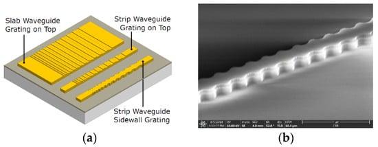
Figure 1.
(a) Schematic representation of chirped gratings on slab and strip waveguides [1]. (b) SEM image of a fabricated strip waveguide with sidewall grating.
In such a grating, we observe different processes depending on the ratio of grating period and wavelength. First, of course, a Bragg grating leads to a reflection in a rather narrow spectral band at a specific design wavelength. At the same time, wavelengths, which are significantly smaller than the design wavelength, are diffracted out by the grating structure (this effect is used, for example, in grating coupler structures). In order to widen the reflection regime, i.e., to broaden the stop band, a chirped grating can be used, where the grating period is varied continuously over the length of the grating. This can be viewed as a sequence of Bragg gratings in series, with a systematic continuous tuning of the design wavelength. If properly designed, such a grating creates a narrow transmission band in between the diffraction and the Bragg reflection regime of the grating at the spectral position of the designed transmission wavelength. The maximum wavelength, which can be covered by Bragg reflection is limited due to the fact that, if the grating pitch is further increased, the diffraction regime is also extended to longer wavelengths. Eventually, this would lead to the diffraction of the desired transmission wavelength. Therefore, we propose a design that utilizes a chirped grating and, at higher wavelengths, material absorption. Material absorption is used to suppress wavelengths in the sub-wavelength regime, which can be achieved by choosing materials with suitable optical properties. This allows one to create a narrow transmission band with a spectrally broad reflection band by tuning the waveguide dimensions and by choosing materials with optical parameters that meet the needs of the design. In total, the filter combines three physical effects: diffraction, Bragg reflection and absorption.
2.1. Theory
Diffraction occurs if the following relation between an incoming and outgoing wavevector holds:
Here, and are the propagation constants of the modes for the incoming and the scattered wave, respectively, is the pitch of the grating and is the diffraction order.
For this study, we assume a single mode propagating towards the grating region with
, , and are the effective mode index, the vacuum wavelength and the wavevector in vacuum, respectively.
For the case of a single fundamental quasi-TE mode in the waveguide, as assumed throughout this work, different situations can be distinguished, depending on the wavelength:
(i) Bragg reflection is the case where the incoming mode is directly reflected by the grating. This corresponds to and we obtain the following condition:
From this, we can deduce the condition for the resonance wavelength at a given grating period or similarly the condition for the grating period, corresponding to a given design wavelength .
(ii) More generally, we can expect reflection into waveguide modes for the conditionswhich leads to the condition . Since the lowest order mode has the highest effective index of refraction, we can expect that scattering towards backpropagating higher order modes happens at a smaller ratio of (c.f. Figure 2a). Thus, for a given grating period, it will happen at smaller wavelengths, as already outlined above.

Figure 2.
(a) Schematic representation of the different processes occurring for different wavelength to grating-period ratios. (b) Schematic representation of a diffraction grating on top of a waveguide, to illustrate the geometry considered in the mathematical description [1].
(iii) The second regime is diffraction out of the waveguide into the radiative modes. These modes form a continuum. The resonance condition is best described in terms of the scattering angles . (See Figure 2b; note that .) The grating equation can be formulated as follows:
Thus, the angle at which a given wavelength is diffracted out of the waveguide is given by the relation: . Scattering perpendicularly away from the waveguide corresponds to and happens for the condition that . The whole regime of scattering occurs for to .
Generally, for a given grating period, diffraction happens at shorter wavelengths than Bragg reflection. Additionally, between the diffraction regime and the reflection, there is a specific gap, where light is transmitted through the waveguide without perturbation.
When focusing on the lowest order of diffraction (m = 1), this gap extends from to . We see that, already, a simple Bragg grating does not only provide a sharp reflection band, but it also introduces blocking due to scattering at lower wavelengths and, in between, features a band with high transmission with a bandwidth of
2.2. Design and Modelling
Our model is based on recent investigations towards an integrated evanescent field non-dispersive infrared (NDIR) sensor platform. The waveguide is formed by a 660-nm poly-Si layer, which is placed on a thin Si3N4 substrate, which also acts as an absorbing layer. Below, we have a thick SiO2 layer, on a Si substrate, which prevents the leaking of the mode to the substrate. On the waveguide, a grating is formed with a depth of 100 nm and a pitch, which is typically linearly increasing.
The simulations were done using COMSOL Multiphysics 5.4. A detailed description of the model can be found in [1].
For the modeling, we considered the SiO2 layer below the waveguide to be infinitely extended. On both sides of the grating, the unperturbed waveguide was elongated. In these sections, numerical ports and an evaluation boundary were placed. Furthermore, the simulation domain (total thickness 5 μm) was terminated on all sides by perfectly matched layers and scattering boundary conditions in order to absorb radiation that reaches the domain boundary and to avoid interference with spurious reflections. On the left side, two numerical interior ports were used, one to excite and detect the fundamental quasi-TE mode and the other one to account for reflections of the first higher order quasi-TE mode. On the right-hand side, both numerical interior ports were used to analyze the transmitted radiation of the two lowest order quasi-TE modes. These interior ports do not absorb radiation and do not affect the wave pattern passing by. In order to determine the total reflection and transmission, the normal power flow through the evaluation boundary on both sides of the grating is evaluated.
The chirped grating geometry was created using a Java code in the COMSOL application builder. The center pitch was 753 nm (calculated using Equation (3)), with the mean effective mode index for elevations and wells. The grating pitch was increased up to a maximum pitch of 1011 nm. On both ends of the filter, the waveguide was extended by 8 μm beyond the grating region, including the port, evaluation boundary and a 1-μm PML section. Three configurations for the grating pitch repetitions (N = 1, 4, 8) were investigated, leading to grating lengths of 106.8 nm, 427.2 nm, and 854.4 µm, respectively.
Within this study, literature values were used for the materials (Air [3], Si [0], Si3N4 [5], SiO2 [5]), which can be easily accessed and are already implemented in COMSOL.
3. Results and Discussion
For a better understanding, we start the discussion with a simple grating featuring a constant pitch. Figure 3 shows simulation results on a grating with 480 lines and a pitch of 771 nm. The pitch was chosen with a passband of 4.26 µm in mind, meaning that the reflection is designed to occur slightly detuned on the long wavelength side. Figure 3a displays the reflectivity of the grating, i.e., the relative intensity of the mode reflected back by the grating within the waveguide. In fact, there are two bands. The Bragg reflection, reflecting the TE0 mode back, has a maximum at 4.35 µm. The second peak at about 3.5 µm corresponds to back scattering into the TE1 mode. This can also be discerned in Figure 4, where the electric field distribution at the grating is displayed. At 4.35 µm and at 3.5 µm, the whole incoming mode is reflected at the beginning of the grating and there is no significant energy left behind the grating. Additionally, while, at 4.35 µm, we see the symmetric TE0 mode, at 3.5 µm, there is a clear anti-symmetric shape reflecting the symmetry of the backreflected TE1 mode, which transports nearly all the energy in this case.
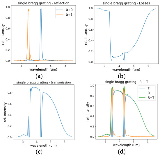
Figure 3.
Simulation results for a Bragg grating with 480 lines and a pitch of Λ = 0.771 µm. (a) reflection, (b) losses, (c) transmission, and (d) reflection and transmission and their sum.

Figure 4.
Plots of the electric field at the Bragg grating for selected wavelengths. Grating parameters were identical to those of Figure 3. Plotted is the amplitude of the electric field at the beginning (plots on the left-hand side) and at the end of the grating (plots on the right-hand side) for initial excitation with a TE0 mode from the left. The wavelengths are (a) 2.5 µm, (b) 3.5 µm, (c) 4.0 µm, (d) 4.35 µm, and (e) 6.0 µm.
If we look at the total losses from the waveguide (Figure 3b), meaning the energy that is lost from the waveguide, we see a strong contribution on the short wavelength side up to about 3.4 µm. This corresponds to the scattering regime, where the energy is scattered out. In the following regime (above 3.4 µm), the energy is kept within the waveguide (reflected or transmitted) but with increasing damping due to absorption. The absorption is mainly caused by the Si3N4-layer with also some contributions from the SiO2. Both materials feature some absorption in the mid-wave infrared regime, which becomes significant for longer wavelengths (see Figure 5b). Figure 3c shows the transmission through the waveguide, where the losses from the waveguide as well as the blocking due to reflection show up. Finally, Figure 3d shows reflection and transmission on the same graph.

Figure 5.
(a) Real part and (b) imaginary part of the effective refractive indices of the three lowest order modes, which are the two lowest-order TE modes as well as the fundamental quasi-TM mode.
Figure 5 shows the effective refractive indices of the first three waveguide modes. These are the two lowest-order quasi-TE-modes as well as the fundamental quasi-TM mode. The latter was not considered at all in the simulations, since, if the initial state is the fundamental TE mode, mixing to TM modes does not play a significant role. Figure 5a shows the real part neff and Figure 5b the imaginary part k of the mode indices. The imaginary part is responsible for damping and we deduce that, for longer wavelengths, damping within the waveguide provides significant blocking, which is important for the functionality of the broad band filter.
The transmission curve of a single Bragg grating (Figure 3c) already defines a filter curve, albeit not an adequate one, with regard to the goal of developing a narrow band transmission filter. However, one can imagine combining a series of such gratings, all with different grating constants, in order to “tailor” the final transmission curve to the design goals. The idea behind the chirped grating approach is to use the combined effect of blocking by diffraction and by reflection from a grating that features a continuously varying grating constant. This is presented in considerable detail in Figure 6, where results for Bragg grating with increasing numbers of subunits with different grating periods Λ are displayed.
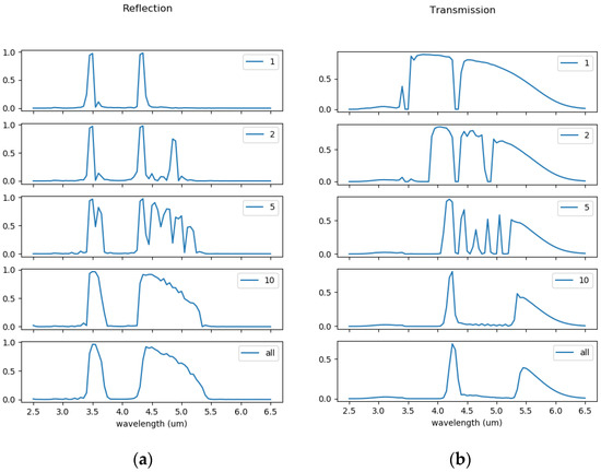
Figure 6.
(a) Reflection and (b) transmission of Bragg grating with increasing number of subunits with different grating periods, . In each case, the overall grating had 480 lines. From top to bottom, the number of distinct grating periods is . (see text for details)
In each case, the overall grating has 480 lines. The upper-most row corresponds to a single Bragg grating with a period of 771 nm. Below, the results are displayed for a grating with 240 lines with a grating period of 771 nm directly followed by 240 lines with a grating period of 891 nm. The bottom line then corresponds to a grating with 480 lines, where the period is continuously varied from 771 to 1.011 µm.
As more and more different grating periods are included in the grating, we see how the Bragg-reflection bands add together. At the same time, we see a broadening of the bands, since each contributing “sub-grating” effectively has a smaller number of lines. Already with a combination of 10 periods, a continuous rejection band is obtained, with a relatively narrow transmission band at the target wavelength of 4.26 µm, together with some long-wavelength contribution. The changes in the transmission spectrum between the “discrete” 10-subunits grating to the continuously varying chirped grating are only minor. Note that the blocking for wavelengths above 4.26 µm directly reflects the combination of the (Bragg-)reflection bands, while in the short wavelength region it is mainly determined by the scattering processes, which dissipate the energy away from the waveguide. The reflection band at around 3.5 µm, which corresponds to scattering from the TE0 to the TE1 mode, lies in the same spectral region, but cannot, for itself, explain the transmission spectrum obtained.
We expect a difference for chirped gratings with the rising or falling chirp of the grating period. This is compared in Figure 7. In particular, the reflection to the higher order mode at short wavelengths only can occur if it happens at the beginning of the grating, because, otherwise, the short wavelengths are already scattered out of the waveguide before reflection can take place. Furthermore, the intrinsic damping, which happens at longer wavelengths, is more pronounced if reflection happens at a later stage in the grating. Thus, for a grating with linearly decreasing pitch, reflection contributions are increased for longer wavelengths. The direction of the grating, however, does not play any significant role for the final transmission achieved, because, for the final transmission spectrum, it does not matter if the energy is blocked by reflection or absorption or is scattered out of the waveguide.
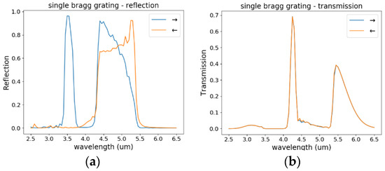
Figure 7.
Comparison of the calculated (a) reflection and (b) transmission through a chirped grating when excited from the low grating-pitch side or from the high-grating pitch side. Note significant differences in the spectrum of the reflected energy, while the transmission remains nearly identical.
Real fabrication processes lead to the significant rounding of the corners (an example for a strip waveguide with side-wall grating is shown in Figure 1b.) To simulate the effect from smoothing, we applied a radius of 50 nm to the sharp edges of the grating (see insets of Figure 8). Simulations were performed with a higher spectral resolution (wavelength steps of 5 nm) in order to more clearly distinguish the effects. The results are shown in Figure 8. Generally, the contrast that can be achieved decreases significantly, even for this minor modification. The blocking contrast does not reach 100% anymore. Otherwise, the transmission curves stay very similar. This indicates that the concept of a transmission filter based on a single chirped grating provides a robust design scheme.
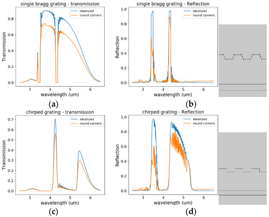
Figure 8.
Comparison of a grating with idealized sharp edges to the case of round corners, with a radius of 50 nm applied. (a) Reflection and (b) transmission through a single Bragg grating. (c) Reflection and (d) transmission through a chirped grating with 480 lines.
4. Conclusions
In this study, we proposed and investigated, in much detail, the concept of a linearly chirped Bragg grating for use as a bandpass filter in the mid-infrared range. To demonstrate the approach, we specifically targeted a bandpass at a wavelength of 4.26 μm, which is of high relevance for CO2 gas sensing. Supported by simulations of simple model structures, we discussed the underlying concept and then validated the concept with realistic simulations, based on a waveguide design, which is currently used for the development of CMOS-compatible evanescent field gas sensors. In principle, the presented filter can be adapted to various applications by engineering the interaction of the design and the used materials.
Funding
This work was performed within the PICASSO-project funded by the BMK in the framework of the program “Produktion der Zukunft” (Prj. Nr. 871417). Part of it was performed within the framework of COMET —Competence Centres for Excellent Technologies, funded by BMK, BMDW, and the Austrian provinces of Carinthia and Styria.
Conflicts of Interest
The authors declare no conflict of interest. The funders had no role in the design of the study; in the collection, analyses, or interpretation of data; in the writing of the manuscript, or in the decision to publish the results.
References
- Ranacher, C.; Jakoby, B.; Consani, C.; Tortschanoff, A. design of a mid-infrared bandpass filter with large rejection bandwidth of silicon photonics. J. Lightwave Technol. 2019, 37, 3770–3776. [Google Scholar] [CrossRef]
- Ranacher, C.; Consani, C.; Vollert, N.; Tortschanoff, A.; Bergmeister, M.; Grille, T.; Jakoby, B. Characterization of evanescent field gas sensor structures based on silicon photonics. IEEE Photonics J. 2018, 10, 1–14. [Google Scholar] [CrossRef]
- Ciddor, P.E. Refractive index of air: New equations for the visible and near infrared. Appl. Opt. 1996, 35, 1566–1573. [Google Scholar] [CrossRef] [PubMed]
- Edwards, D.F.; Ochoa, E. Infrared refractive index of silicon. Appl. Opt. 1980, 19, 4130–4131. [Google Scholar] [CrossRef] [PubMed]
- Kischkat, J.; Peters, S.; Gruska, B.; Semtsiv, M.; Chashnikova, M.; Klinkmüller, M.; Fedosenko, O.; Machulik, S.; Aleksandrova, A.; Monastyrskyi, G.; et al. Midinfrared optical properties of thin films of aluminum oxide, titanium dioxide, silicon dioxide, aluminum nitride, and silicon nitride. Appl. Opt. 2012, 51, 6789–6798. [Google Scholar] [CrossRef] [PubMed]
Publisher’s Note: MDPI stays neutral with regard to jurisdictional claims in published maps and institutional affiliations. |
© 2019 by the authors. Licensee MDPI, Basel, Switzerland. This article is an open access article distributed under the terms and conditions of the Creative Commons Attribution (CC BY) license (https://creativecommons.org/licenses/by/4.0/).