1. Introduction
The autonomous mobile platforms will be more and more common for interoperation logistics [
1,
2]. The key feature on how to reach a high duty cycle of the battery powered platform is the use of the high power charging (HPC) system [
3] or battery swapping station [
4]. Most of the platforms use proprietary solution for charging [
5], mostly because a standardized automatic connection device underbody (ACDU) interface [
6] is still not available. However, thanks to the HPC systems, now widely expanding in public charging infrastructure for on-road vehicles, the use of standardized solution makes sense. The disadvantage of this standardized solution is that the used combined charging system (CCS) type 2 [
7] is not designed for autonomous robotic handling but rather for human service.
2. Quick Overview of Possible Solution
We concerned ourselves only with the robotic plug-in charging system, because battery swap needs an additional infrastructure and floor space.
The localization of the mobile platform can be handled by sensor fusion of several different sensor principles [
8,
9]. Typically, odometry, nine DOF sensor, combines accelerometers, gyroscopes and magnetometers, GPS or ultra-wideband (UWB) absolute localization [
10], and even advanced visual systems. This attitude is not discussed in the paper. The typical outputs of this localization system are not precise enough to reach a charging connector without additional localization system or mechanical guidance.
3. Materials and Methods
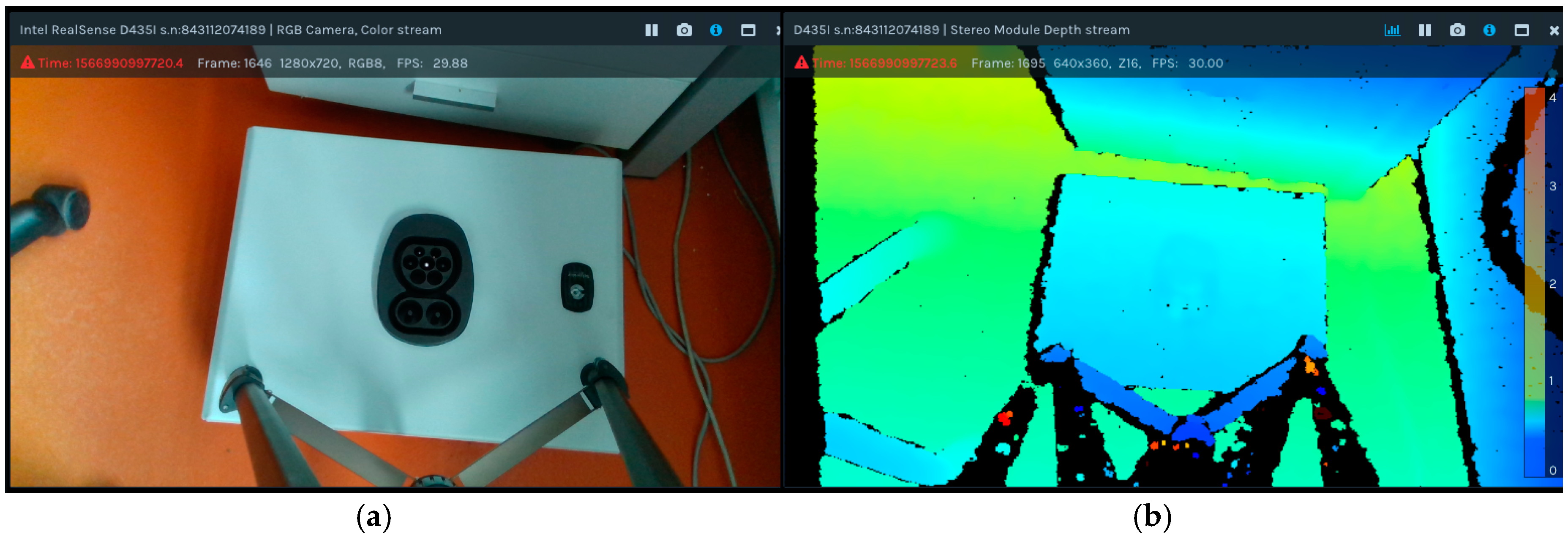
For our experiment, we use a dummy model of the CCS type 2 plug and the vehicle inlet. The UR3 robot is suitable as a low power variant and an Intel Realsense D435i camera was used. MATLAB was selected as the development environment. The camera was steady, not on a robotic arm, but in the future it can be changed. The basic camera image is in
Figure 1.
4. Results
The problem can be separated into two sections, the results of image processing, which provide the position and orientation for the second part, which is the robotic control.
4.1. Image Processing
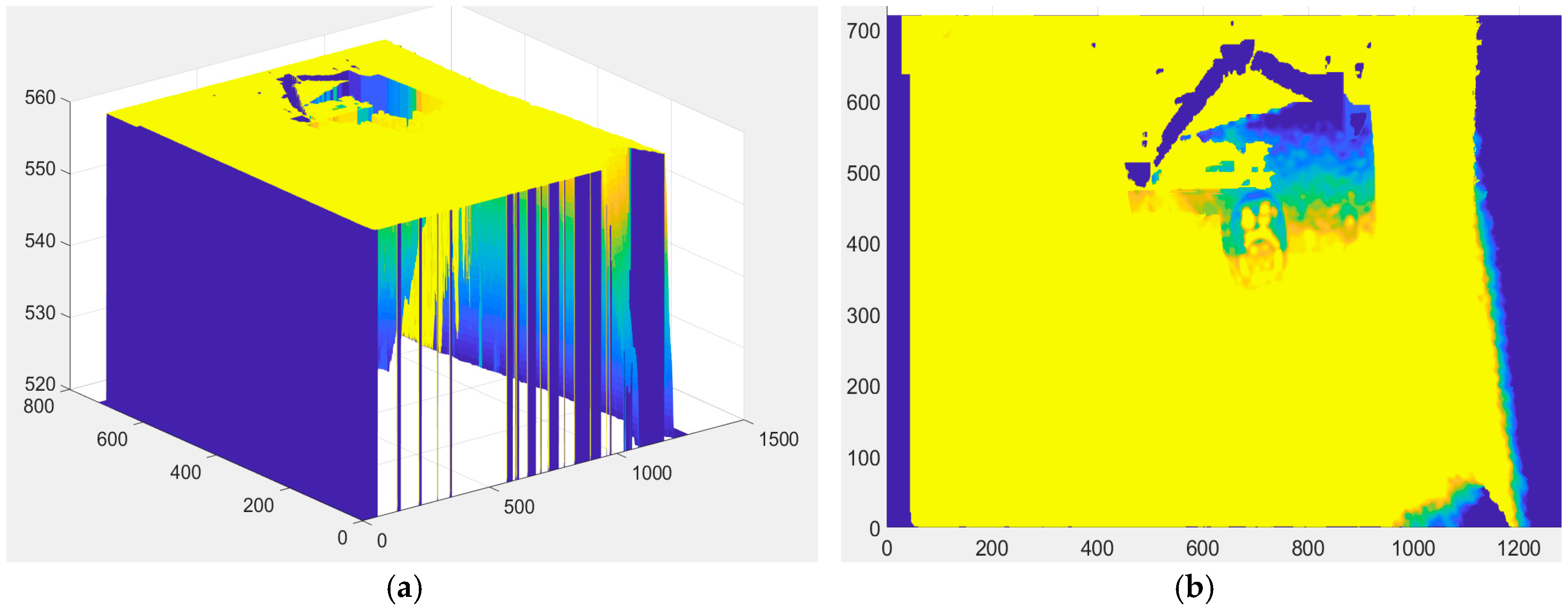
The data is provided through SDK by a single array, so it must be restructuralized to (m-n- …) in MATLAB to display the image. Thanks to a known camera distance from inlet
Figure 2a, we can filter depth data to get the X-Y plane of the cabinet,
Figure 2b.
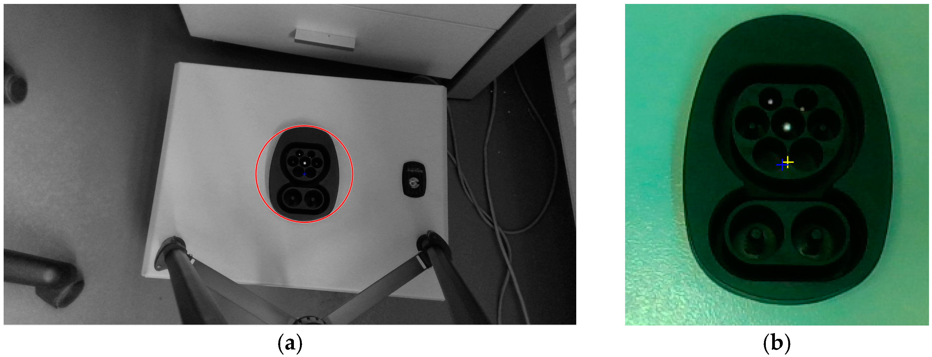
The inlet recognition is based on a visible image pattern matching, depth camera information verification that improves the robustness of the solution. The main point is in the visible image processing, where thanks to the elliptical shape of the CCS inlet we find the area with proper contour and size, results are displayed in
Figure 3.
The center point is reliably detected; the blue one was based on a different algorithm, where the shadow slightly influences the position. From the optical image, we therefore get the center point and orientation of the object.
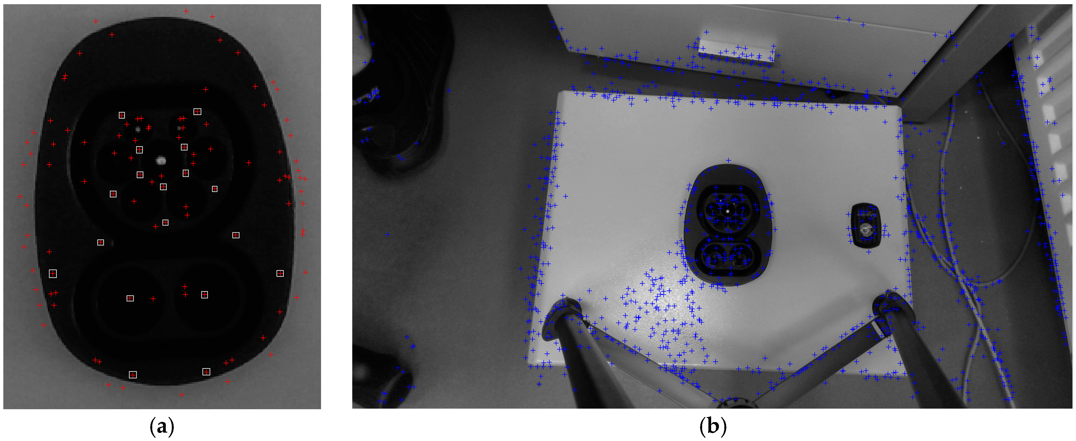
The next level of image processing is pattern matching, where preimage is labeled and then found in the picture,
Figure 4. We have to say, that this algorithm really depends on sensitivity setting for labeling. This algorithm is iterative, when the center point is detected out of the depth region, the results are wrong and the sensitivity is adjusted and algorithm is started again, five times maximum.
4.2. Robotic Control
The robotic control is based on TCP/IP communication, where the tool of CCS type 2 plug is set up on the robot. Input data are the center point and Z-tool rotation orientation, the output data are six DOF force and torques measured by the robot. Before first use, a simple camera calibration must be done, where the pairs of camera point and robotic coordinates are matched together by affine transformation. The plugging process is separated into several steps.
“Reaching the first contact” (orientation of tool Z-tool axis rotation is not compensated). The position setpoint is above the plane and the robot moves to Z-tool axis force threshold.
“Force controlled motion” (adjustment of position X-Y plane to minimize tangential forces).
“Partial plug-in” (Z-tool rotation from positive torque threshold to negative torque threshold and setting the orientation to half between those limits.)
“Finalization of plug-in” to reach the proper depth from initial contact to ensure the full plug-in. This operation must be made within force torque limits, to ensure proper orientation in X, Y axis.
Those steps are nowadays realized in MATLAB, thanks to faster software development, but for the final stage they will be implemented into the robotic controller for simplification of control process.
5. Discussion
The image processing uses several approaches on how to detect the CCS type 2 vehicle inlet. The depth information is used as “candidate valley” for verification. For final realization, it seems the “eye on hand” arrangement is better. The mandatory enhancement must be made for lighting, since daylight and fluorescent ambient lighting (for worst case study of the algorithm) were used for our experiment. The improvement in lighting helps to feature extraction on the inlet and can significantly improve the pattern matching.
The last problem is in force torque control during plug-in operation, where the end effector force torques are reconstructed from joints values, independent force torque sensor could help, and such solution will be used in further research. The iterative attitude via several tool axis is time consuming, in the future we would like to develop an algorithm to measure the forces and torques and calculate the compensative motion in one-step for all axis.
The important fact is that the recognition algorithm is reliable, there are almost no positive false, the inlet is recognized, but not present. The negative false are typical in case, when part of the inlet is out of range or during bad lighting conditions. This must be improved during the next phase of research by better lighting and camera on robotic hand arrangement. However, the MATLAB with image processing and robotic toolboxes is a good environment for development.
Author Contributions
Conceptualization, J.C. and P.J.; methodology, J.C. and P.J.; software, J.C.; investigation, J.C.; resources, P.J.; writing—original draft preparation, J.C.; writing—review and editing, P.J.; supervision, P.J.
Funding
The result was obtained through the financial support of the European Union in the frames of the project “Modular platform for autonomous chassis of specialized electric vehicles for freight and equipment transportation”, Regulation number CZ.02.1.01/0.0/0.0/16_025/0007293.
Conflicts of Interest
The authors declare no conflict of interest. The funders had no role in the design of the study; in the collection, analyses, or interpretation of data; in the writing of the manuscript, or in the decision to publish the results.
References
- Bacik, J.; Durovsky, F.; Biros, M.; Kyslan, K.; Perdukova, D.; Padmanaban, S. Pathfinder–Development of Automated Guided Vehicle for Hospital Logistics. IEEE Access 2017, 5, 26892–26900. [Google Scholar] [CrossRef]
- Hossain, S.; Ali, M.; Jamil, H.; Haq, M. Automated Guided Vehicles for Industrial Logistics—Development of Intelligent Prototypes Using Appropriate Technology. In Proceedings of the 2nd International Conference on Computer and Automation Engineering (ICCAE), Singapore, 26–28 February 2010. [Google Scholar] [CrossRef]
- Phoenix Contact: High Power Charging—CCS-Based Fast Charging with up to 500 A, 2019. Available online: https://www.phoenixcontact.com/assets/downloads_ed/global/web_dwl_promotion/52007586_EN_HQ_E-Mobility_LoRes.pdf (accessed on 21 October 2019).
- Mak, H.; Rong, Y.; Shen, Z. Infrastructure Planning for Electric Vehicles with Battery Swapping. Manag. Sci. 2013, 59, 1557–1575. [Google Scholar] [CrossRef]
- Staubli: Automatic Rapid Charging Solution QCC for AGV, 2019. Available online: http://ec.staubli.com/AcroFiles/Catalogues/SZ_APP-RapidCharge-AGV-11014168_(en)_hi.pdf (accessed on 21 October 2019).
- Charinev.Org. 2019. Available online: https://www.charinev.org/acd/?no_cache=1 (accessed on 21 October 2019).
- CharIN: Combined Charging System Specification, 2019. Available online: https://www.charinev.org/ccs-at-a-glance/ccs-specification/ (accessed on 21 October 2019).
- Fauser, T.; Bruder, S.; El-Osery, A. A Comparison of Inertial-Based Navigation Algorithms for a Low-Cost Indoor Mobile Robot. In Proceedings of the 12th International Conference on Computer Science and Education (ICCSE), Houston, TX, USA, 22–25 August 2017; pp. 101–106. [Google Scholar] [CrossRef]
- Cernohorsky, J.; Jandura, P.; Mach, O. Mobile Robot Localization and Object Description. In Proceedings of the 18th International Carpathian Control Conference (ICCC), Sinaia, Romania, 28–31 May 2017; pp. 503–506. [Google Scholar] [CrossRef]
- Wang, J.; Gao, Y.; Li, Z.; Meng, X.; Hancock, C.M. A Tightly-Coupled GPS/INS/UWB Cooperative Positioning Sensors System Supported by V2I Communication. Sensors 2016, 16, 944. [Google Scholar] [CrossRef] [PubMed]
| Publisher’s Note: MDPI stays neutral with regard to jurisdictional claims in published maps and institutional affiliations. |
© 2019 by the authors. Licensee MDPI, Basel, Switzerland. This article is an open access article distributed under the terms and conditions of the Creative Commons Attribution (CC BY) license (https://creativecommons.org/licenses/by/4.0/).
