Abstract
Air-to-air energy recovery ventilators (ERVs) are able to reduce the required energy to condition ventilation air in buildings. Among different types of ERVs, fixed-bed regenerators (FBRs) have a higher ratio of heat transfer area to volume. However, there is limited research on FBRs for HVAC applications. This paper presents preliminary experimental and numerical research of FBRs at the University of Saskatchewan. The numerical and experimental results for effectiveness of FBR agree within experimental uncertainty bounds and the results agree with available empirical correlations in the literature.
1. Introduction
Building energy consumption accounts for around one-third of Canada’s energy consumption [1] and about 55% of the total energy consumed in buildings goes to heating, ventilation and air conditioning (HVAC) systems [2]. HVAC systems are responsible for providing appropriate indoor air temperature, humidity and air quality, which impact the health, comfort and productivity of occupants [3]. Air-to-air energy recovery ventilators (ERVs) recover energy from the exhaust air stream (discharged from buildings) and transfer this energy to the supply air stream for ventilation. One specific type of air-to-air ERV, which has high ratio of heat transfer area to volume, is a fixed-bed regenerator (FBR).
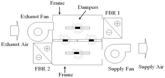
Figure 1 shows a schematic of an HVAC unit for energy recovery. This unit consists of two FBRs, two fans, and dampers. The position of the dampers determines the path for the exhaust and supply airflows. To transfer energy between exhaust and supply air streams, the FBRs in Figure 1 undergo two phases of energy exchange. In the first phase, the dampers are positioned as shown in Figure 1 and the exhaust air stream flows through FBR1 and the supply air stream flows through FBR 2. The exhaust air heats FBR 1, while FBR 2 heats the supply air. In the second phase, all the dampers turn 90 degrees so that the flow through the FBRs reversed. The exhaust air flows through FBR 2 and the supply air flows through FBR 1. Thus the exhaust air heats FBR 2, while the supply air is heated by FBR 1. A complete cycle of operation of an FBR includes ‘hot flow period’ and ‘cold flow period’. Therefore in an FBR, the energy from the hot air stream (the exhaust air) is intermittently stored in the FBR before it is transferred to cold air stream (the supply air). Furthermore, the position of dampers enables the unit to operate in the different modes of standby, free cooling and optional recirculating of exhaust air [4]. At quasi-steady state condition the outlet temperature of an FBR varies with time but repeats a cyclic change.

Figure 1.
A schematic of an HVAC unit for energy recovery with two FBR cores.
Despite various applications of FBRs in furnaces and heat recovery systems in industries such as aluminum, cement and glass making, the available literature on the applications of FBRs for HVAC systems is limited [5]. Nizovtsev et al. [6] performed an experimental study on a FBR for single room ventilation. They also presented a simple one-dimensional, physical-mathematical model. They showed that the effectiveness of exchanger decreases linearly as the airflow rate increases. The influence of condensation and vaporization on the effectiveness of the FBR was studied by Nizovtsev et al. [7]. Chang et al. [8] presented experimental and theoretical research of FBR for air conditioning applications. The effect of the cycle time on the effectiveness of the FBR was examined and results showed that an optimal effectiveness was achieved with a cycle time of 3 minutes. Figure 1: A schematic of an HVAC unit for energy recovery with two FBR cores.
Due to the limited research on FBRs in HVAC applications, an experimental facility, and a numerical model are presented in this paper. A small-scale test method, which is convenient and less expensive compared to full-scale test method [9,10], is adopted in this research.2.
2. Experimental and Theoretical Methods
The performance of a heat exchanger is quantified using sensible effectiveness, which is defined as the ratio of the actual heat transfer rate to the maximum possible heat transfer rate. Sensible effectiveness of regenerative exchangers is a function of the overall number of transfer units (NTU) and matrix heat capacity ratio on the supply or exhaust side (𝐶𝑟∗) [11]. Therefore, effectiveness is defined as:
where Te,i, Ts,i are the inlet temperature of the exhaust and supply airflows, respectively. ṁsupply and ṁexhaut are the mass flow rate of supply and exhaust air, respectively. The temperature of the air leaving the FBR varies with time and , and , are the time-averaged supply and exhaust outlet air temperatures, which are defined as follows:
where 𝜏c and 𝜏h are the ‘cold period’ and ‘hot period’, respectively.
The challenges associated with full-scale testing of regenerators are reported in several literatures [9,12]. Major problems include the requirement of a large volume flow rate, expensive instrumentation and the time associated with conducting experiments. Fathieh et al. [9] suggested a transient test method to evaluate the performance of rotary regenerators by performing tests on small-scale parallel-plate heat exchangers.
2.1. Experimental Facility
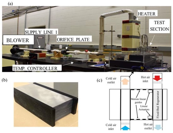
To determine the effectiveness of FBRs a small-scale test facility is developed at the University of Saskatchewan as shown in Figure 2a. The experimental facility consists of an air supply section and a test section (see Figure 2c). The air supply is provided by two blowers that continuously supply air to the test section. The test section consists of a parallel plate heat exchanger (made of thin sheets of Aluminum 3003) as shown in Figure 2b that is moved between the two air streams using pneumatic controlled linear actuator. The heat exchanger geometrical and thermo-physical properties are presented in Table 1.

Figure 2.
(a) Small scale test facility for the performance evaluation of FBRs (b) a schematic of test section and (c) a picture of parallel-plate heat exchanger for the test section.

Table 1.
Exchanger (channel and sheets) geometrical and thermo-physical properties.
The flow rate to the test section is controlled by adjusting the voltage supplied to the blowers and the air flow rate is measured by the orifice plates on each supply line. One of the air streams is heated to 40 °C (hot stream temperature) using a PID controlled duct heater (Omega AHF- 06120, 600 W) while the other stream is kept at room temperature of 22 °C (cold stream temperature). The temperature of the hot and cold air streams at the inlet and outlet of the exchanger are measured using calibrated T-type thermocouples with an uncertainty of ±0.2 °C. During a test, the heat exchanger is moved periodically between the hot and cold air streams representing a FBR.
2.2. Numerical Model
A one-dimensional numerical model is used to analyze the FBR in this study. Flow inside the exchanger is assumed to be laminar and incompressible and the bulk mean temperature inside the channel is used to model the heat transfer process. The following governing equations for both the airflow and matrix are solved numerically [13]:
where t, x, 𝜌, 𝐶p, 𝑘, U, h, L and T are time, axial coordinate, density, specific heat, thermal conductivity, mean airflow velocity, convective heat transfer coefficient, length of channel and temperature, respectively. Subscripts ‘g’ and ‘m’ are used to represent the gas and matrix variables, respectively. Ag, 𝐴s and 𝐴m represent the cross sectional area of the channel, heat transfer surface area and crosssectional area of the exchanger sheet. Appropriate boundary conditions are also implemented to solve the problem [13].
3. Results and Discussions
The results will be presented for two different air velocities approaching the exchanger and inlet air temperatures of 41 °C and 21 °C (Table 2).

Table 2.
Operating conditions of two tests for this study with dimensionless groups of NTUo and Cr*.
Figure 3 shows the experimental and numerical quasisteady-state outlet air temperatures of the FBR at an air face velocity of 0.7(m/s). The outlet temperature increases during the hot period and decreases during the cold period as expected. Figure 3 shows a good agreement between the experimental and numerical results.

Figure 3.
Quasi-steady-state outlet air temperature profile of FBR at the face velocity of 0.7 m/s (a) and at the face velocity of 1.6 m/s (b).
Figure 4 presents numerical and experimental results of the outlet temperature of the FBR for face velocity of 1.6 (m/s). Compared to the lower face velocity (Figure 3), as the face velocity increases the outlet air temperature profile of FBR shifts up during the hot period and shifts down during the cold period. Therefore, the airflow is less cooled during the hot period and less heated during the cold period; this means that the effectiveness is decreased.

Figure 4.
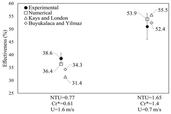
Measured sensible effectiveness and comparison with the numerical and empirical correlations of Kays and London [14] and Buyukalaca and Yilmaz [15] for two operating conditions. The error bars represent the experimental uncertainty bounds at the 95% confident interval.
The sensible effectiveness of the FBR can be calculated from the periodic temperature profiles in Figure 3. From Figure 3a, the sensible effectiveness can be obtained as the ratio of the actual heat transfer rate (the double shaded (red and blue) area in Figure 3a) to the maximum possible heat transfer rate (shaded (red) area in Figure 3a). Comparing these areas for the two operating conditions, it can be concluded that the sensible effectiveness at the higher face velocity (lower NTUo and Cr*) is lower than the sensible effectiveness at the lower face velocity.
The results for effectiveness of FBR are also compared against the available empirical correlations of Kays and London [14] and Buyukalaca and Yilmaz [15]. Where according to Kays and London [14], this correlation is accurate for balanced flow rate in the following ranges: 2 < NTUo < 14 for Cr* < 1.5, NTUo < 20 for Cr* = 2, and entire range of of NTUo for Cr* > 5. The Buyukalaca and Yilmaz [15] correlation claims to be accurate in all values of NTUo and Cr*. The comparison of numerical and experimental effectiveness along with the values from the empirical correlations are presented in Figure 4. The numerical and experimental results agree within the experimental uncertainty bounds. Good agreement are also observed between the results and the prediction of the Kays and London [14] and Buyukalaca and Yilmaz [15] correlations. The Kays and London correlation predict a lower value at face velocity of 0.7 m/s (NTUo = 0.77) mainly because the values of NTUo and Cr* are outside the range of applicability of the Kays and London [14] correlation.
4. Conclusions
This paper uses a small-scale experimental facility and a numerical model to determine the sensible effectiveness of fixed-bed regenerators (FBRs) for HVAC applications. The numerical and experimental results for effectiveness agree with the available empirical correlations. It was also observed that increasing the NTUo and Cr* will increase the effectiveness.
Future works will use the model and experimental facility to optimize FBRs for simultaneous heat and moisture transfer.
Author Contributions
Hadi Ramin prepared numerical model and wrote the paper except for the experimental section. This section is written by Eswaran N. Krishnan; he also conducted the experiments. Carey J. Simonson supervised the research and review the paper.
Acknowledgments
Financial support from the College of Engineering and Postdoctoral Studies of the University of Saskatchewan, National Science and Engineering Research Council (NSERC) and Tempeff North America Inc., Winnipeg are appreciated.
Conflicts of Interest
The authors declare no conflict of interest.
References
- Natural Resources Canada, Energy Use Data Handbook 1990–2015. Available online: http://oee.nrcan.gc.ca (accessed on 25 July 2018).
- Al-Abidi, A.A.; Bin Mat, S.; Sopian, K.; Sulaiman, M.Y.; Lim, C.H.; Abdulrahman, T. Review of thermal energy storage for air conditioning systems. Renew. Sustain. Energy Rev. 2012, 16, 58025819. [Google Scholar] [CrossRef]
- Singh, J. Impact of indoor air pollution on health, comfort and productivity of the occupants. Int. J. Aerobiol. 1996, 34, 121–127. [Google Scholar] [CrossRef]
- Tempeff Ventilation Technologies. How energy recovery ventilation works. Available online: https://www.tempeffnorthamerica.com/ (accessed on 25 July 2018).
- Sadrameli, S.M. Mathematical models for the simulation of thermal regenerators: A state-of-the-art review. Renew. Sustain. Energy Rev. 2016, 58, 462–476. [Google Scholar] [CrossRef]
- Nizovtsev, M.I.; Borodulin, V.Y.; Letushko, V.N.; Zakharov, A.A. Analysis of the efficiency of air-to-air heat exchanger with a periodic change in the flow direction. Appl. Thermal Eng. 2016, 93, 113–121. [Google Scholar] [CrossRef]
- Nizovtsev, M.I.; Borodulin, V.Y.; Letushko, V.N. Influence of condensation on the efficiency of regenerative heat exchanger for ventilation. Appl. Therm. Eng. 2017, 111, 997–1007. [Google Scholar] [CrossRef]
- Chang, C.C.; Chen, S.L.; Lin, T.Y.; Chiang, Y.C. Experimental and theoretical investigation of regenerative total heat exchanger with periodic flow for air-conditioning systems. Int. J. Refrig. 2017, 81, 123–133. [Google Scholar] [CrossRef]
- Fathieh, F.; Besant, R.W.; Evitts, R.W.; Simonson, C.J. Determination of air-to-air heat wheel sensible effectiveness using temperature step change data. Int. J. Heat Mass Transf. 2015, 87, 312–326. [Google Scholar] [CrossRef]
- Fathieh, F. A Novel Transient Testing Method for Heat/Energy Wheel Components. Ph.D. Thesis, University of Saskatchewan, Saskatoon, SK, Canada, July 2016. [Google Scholar]
- Shah, R.K.; Sekulic, D.P. Fundamentals of heat exchange design; John Wiley & Sons, Inc.: Hoboken, NJ, USA, 2003. [Google Scholar]
- Abe, O.O.; Simonson, C.J.; Besant, R.W. Effectiveness of energy wheels from transient measurements. Part 1: Prediction of effectiveness and uncertainty. Int. J. Heat Mass Transfer 2006, 49, 52–62. [Google Scholar] [CrossRef]
- Simonson, C.J.; Besant, R.W. Heat and Moisture Transfer in Desiccant Coated Rotary Energy Exchangers: Part I. Numerical Model. HVAC&R Res. 1997, 3, 325–350. [Google Scholar]
- Kays, A.L.; London, W.M. Compact Heat Exchangers; McGraw-Hill Inc: New York, USA, 1984. [Google Scholar]
- Buyukalaca, O.; Yilmaz, T. Influence of rotational speed on effectiveness of rotary-type heat exchanger. Heat Mass Transfer 2002, 38, 441–447. [Google Scholar] [CrossRef]
Disclaimer/Publisher’s Note: The statements, opinions and data contained in all publications are solely those of the individual author(s) and contributor(s) and not of MDPI and/or the editor(s). MDPI and/or the editor(s) disclaim responsibility for any injury to people or property resulting from any ideas, methods, instructions or products referred to in the content. |
© 2019 by the authors. Licensee MDPI, Basel, Switzerland. This article is an open access article distributed under the terms and conditions of the Creative Commons Attribution (CC BY) license (https://creativecommons.org/licenses/by/4.0/).