1. Introduction
To analyze and design RC structures to resist blast loads, the Single-Degree-of-Freedom (SDOF) generally represents a simplified and cost-effective method capable of deliver good predictions on the structural behavior of the component and it has been broadly used by many authors.
Yet, limited research is available when it refers to the use of SDOF methods for FRP strengthened RC structures. Blast performance of FRP retrofitted unreinforced masonry walls was studied by Myers et al. [
1] using an energetic resolution of the Single-Degree-of-Freedom method, assuming full bond between FRP and the concrete substrate. Their results presented a good prediction of the failure mode when compared to experimental results. Pezzola et al. [
2] studied the blast performance of CFRP retrofitted RC walls, where the composite material was included in the analysis assuming it behaves like tensile reinforcement. The solution was controlled by a strain limit representation of the FRP debonding.
Although these studies have included the FRP contribution into the analysis, they did not include the full characterization of debonding into the SDOF modelling.
The post-FRP failure force-deformation characteristics of retrofitted RC flexural members are of extreme importance, especially when the structure is subjected to unexpected or accidental loads, such as blast loading, where the structure can still offer some resistance after the premature debonding appears. Since the accuracy of the SDOF method significantly depends on the accuracy of the adopted resistance function, it is important to correctly model it, where debonding predictions must be included in order to better estimate the maximum displacement and overall blast performance of the structural member. This paper combines the experimental and numerical testing of one-way slabs retrofitted with FRP under quasi-static loading with the analytical resolution of a SDOF system to analyze the influence of the FRP-to-concrete failure on the blast resistance of a RC structure.
2. Experimental Testing
2.1. Test Specimens and Material Characterization
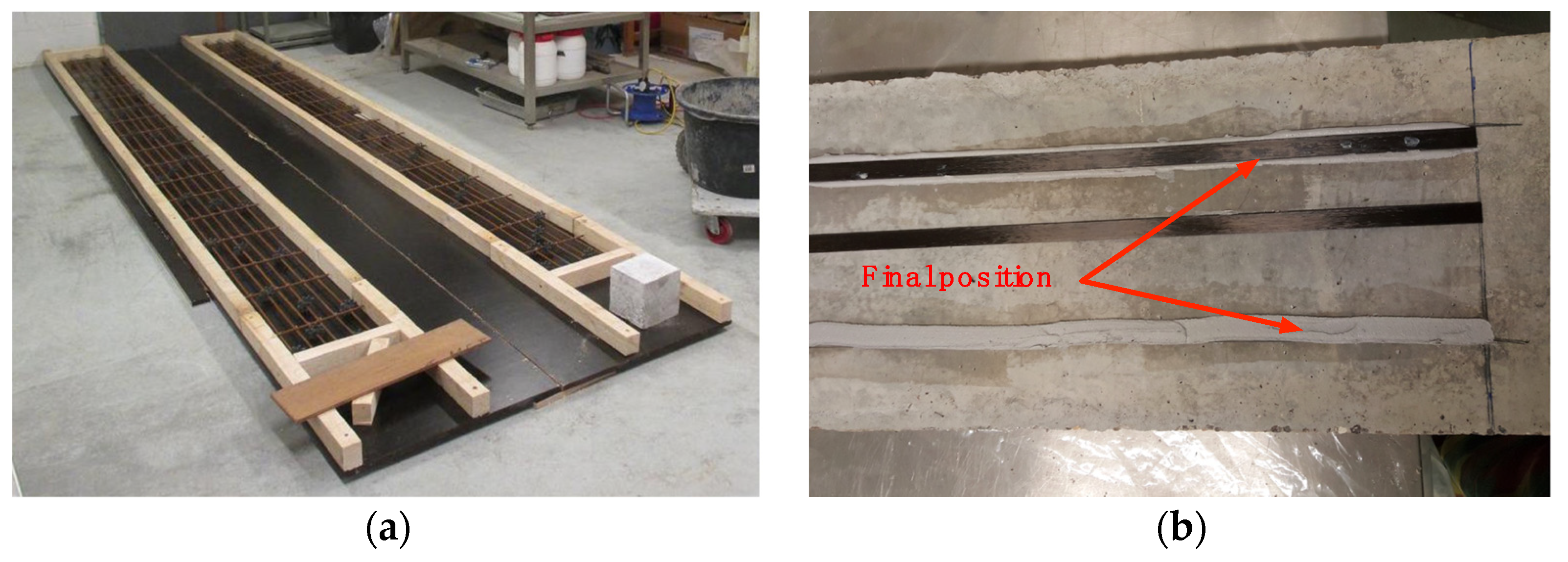
Two 2.2 × 0.3 × 0.06 m one-way slabs are manufactured with C25/30 concrete and S500 structural steel. Six 6 mm rebars are used in the longitudinal direction, where 17 rods equally spaced are used in the transversal direction to keep a uniform 4 cm spacing between the longitudinal reinforcement. One of the slabs is externally reinforced by two CFRP strips applied on the concrete surface with the epoxy resin.
Figure 1 shows the manufacturing of the slabs and FRP application.
The average 28-day compressive strength of the concrete was found to be 32.88 MPa and it was determined using 3 identical standard cubes. Mix proportions of concrete is summarized in
Table 1. Deformed steel rods of grade 500 with a diameter of 6 m are used as reinforcing steel. The FRP-strengthening of the concrete members is done using uniaxial Sika CarboDur S1.525 strips with 15 mm width and 2.5 mm thickness. The strips have a Young modulus of 165 GPa and a tensile strength of 3.1 GPa. The epoxy system SikaDur-30 is characterized by a Young Modulus of 9.6 GPa and a tensile and shear strength of 24 and 14 MPa, respectively.
2.2. Testing Method
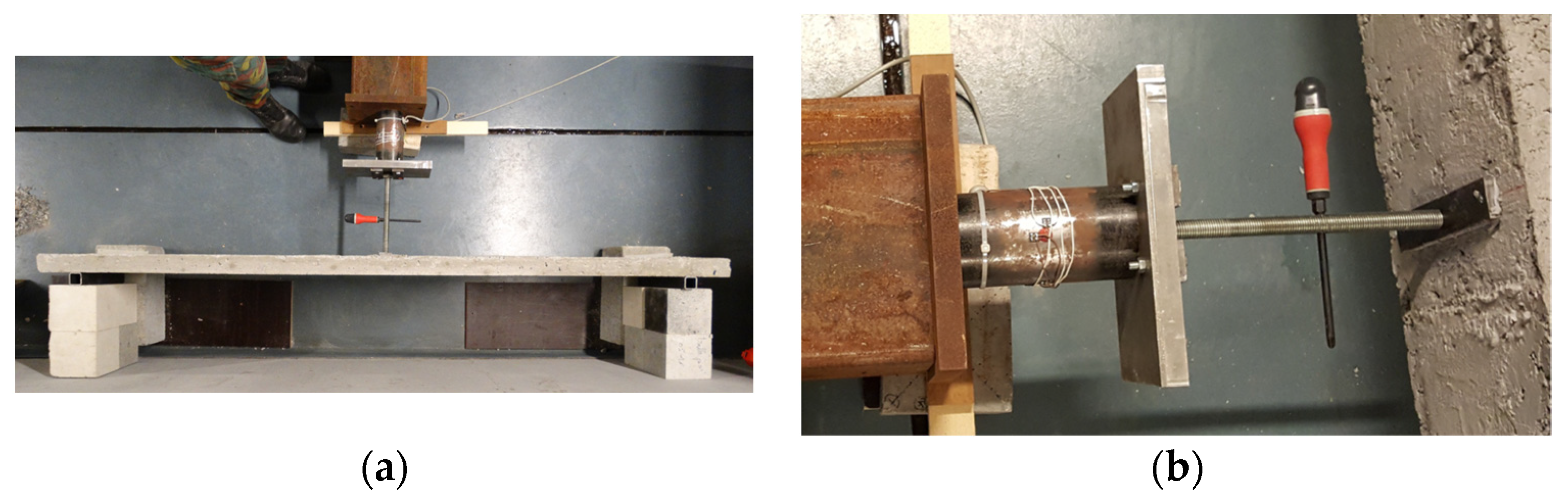
To evaluate the bending performance of the specimens, experiments are carried out in a 3-point bending setup with displacement control, as shown in
Figure 2a. The slab is in direct contact with two steel bars to ensure a minimum contact area. These bars are then in contact with concrete cubes acting as supports. The distance between supports is 2 m and they are positioned against a wall. The single-point load is applied on the concrete surface where a 10 mm thickness metal plate is used as an interface between the slab and the loading device.
Figure 2b shows the loading apparatus.
2.3. Experimental Results
The performance and effectiveness of EBR technique in the enhancement of the flexural capacity of small one-way slabs is presented here. Test results are expressed in terms of their first crack load-carrying capacity, yield load-carrying capacity and ultimate load-carrying capacity, provided in
Table 2.
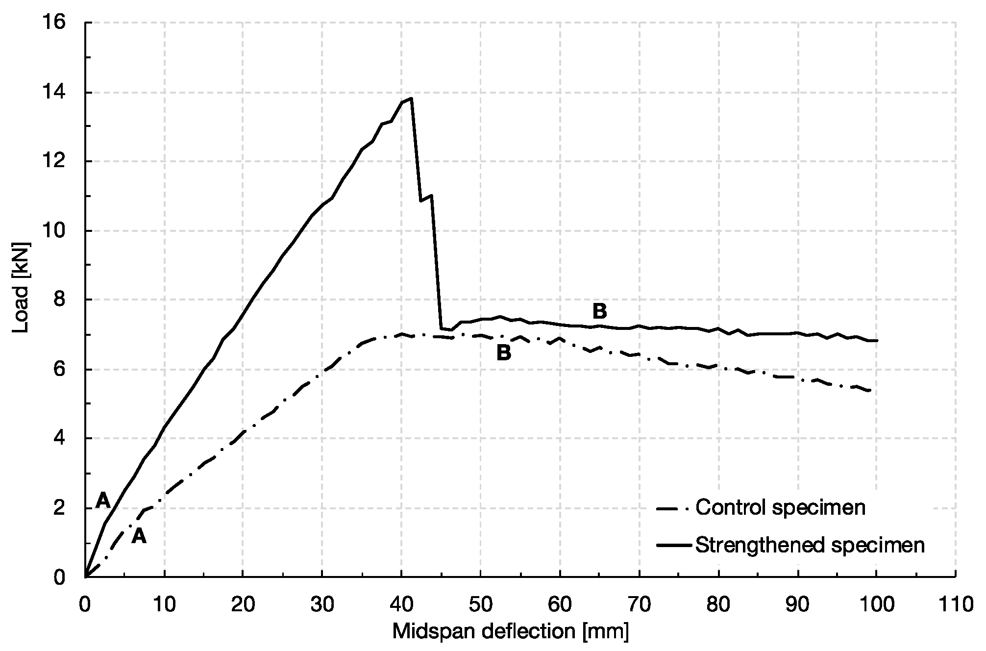
Figure 3 shows the relationship between the load applied and the mid-span deflection for the tested specimens.
Both the control specimen and the slab externally strengthened with FRP exhibited linear behaviour prior to cracking, followed by the development of cracks and large deflection. Prior to the cracking point, two major cracks started to develop in the mid-span. At 6.9 kN, the control slab starts to yield, where the load is kept somewhat constant while the deflection increases. The slab failed at a load of 6.3 kN by concrete crushing (point B).
The strengthened slab remained in the elastic-plastic domain up to a maximum load of 13.9 kN, where a sudden ripping-off of the two strips was observed. As the debonding happened in a very fast way, it was not possible to find out where it initiated. It was characterized by the detachment of a thin layer of concrete at the bottom of the slab, which is one of the main failure mechanisms of the FRP due to the high strength characteristics of the adhesive used and is in accordance with the observations of Khalifa [
3] and Zheng et al. [
4].
The debonding of the FRP was followed by an immediate formation of a plastic hinge. The applied load kept rather constant until the failure of the slab, by concrete crushing. In general, although the slab externally strengthened with two strips of CFRP did not have a considerable enhancement in the ultimate load in comparison with that of the un-strengthened slab, the maximum displacement before failure had an increase of 18%. The maximum load carrying capacity had an enhancement of 115%.
3. Numerical Modelling
3.1. Geometrical Modelling and Loading Conditions
The finite-element (FE) code LS-DYNA is used to simulate the flexural response of the one-way slabs presented in the experimental program described above.
Full bond between the rebars and the surrounding concrete is assumed. To ensure a correct representation of the experimental setup, a controlled displacement is applied to the slab.
Given the reduced thickness of the bond layer between the CFRP strips and the concrete volume, the epoxy adhesive is not explicitly modelled. Instead, the contact ∗AUTOMATIC_SURFACE_TO SURFACE_TIEBREAK is used, which keeps a full connection between the elements until a failure criterion based on the normal and shear stresses is reached. Failure of concrete-to-FRP interface is calibrated based on the experimental results.
To reduce the computation time and to allow for a more refined mesh, a half-symmetry model with appropriate boundary conditions is used.
3.2. Material Models
The material model *MAT_CSCM_CONCRETE model is employed to describe the concrete behavior, where the steel response is represented by the model *MAT_PIECEWISE_LINEAR_PLASTICITY, which allows the use of an arbitrary stress-strain curve. In order to describe the mechanical performance of the externally bonded strips, material model *MAT_ENHANCED_COMPOSITE_DEMAGE is used. It can define the orthotropic properties of the material with multiple failure criteria and it is based on the Chang-Chang criterion [
5]. Material properties used in the FE analysis are in accordance with the experimental program.
3.3. Numerical Results
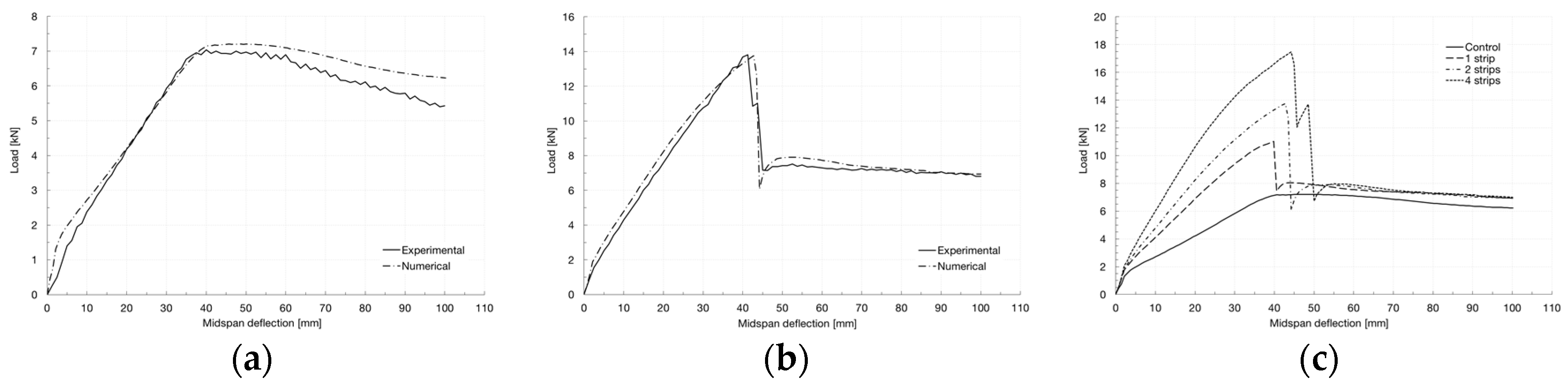
Comparisons between load-deflection plots from the experiments and FEA are shown in
Figure 4a,b. In general, the numerical results show an overall good agreement with the experimental data for both the control specimen and the FRP-strengthened one. The formation of a plastic hinge and the post-peak softening phase visible on the control specimen,
Figure 4a, are well captured by the numerical model. The same can be observed in the case of the strengthened slab,
Figure 4b, where the numerical model presents a similar cracking phase stiffness and a good prediction of the damage phase, after the formation of a plastic hinge. The numerical model presents a good prediction of the FRP debonding as well. These observations indicate that in general, the proposed model is able to match reasonably well with the recorded data. That said, two other different strengthening schemes were numerically tested: slab with one centered strip and slab with four centered strips with 4.8 cm spacing.
Figure 4c presents a comparison overview of the four numerical studies performed. It is clear an increase of the stiffness and flexural capacity of the slabs with the increase in the number of CFRP strips. As a result, the composite action tends to be kept until a higher load level, with a maximum variation of 58.6% for the case of a slab retrofitted with four strips of CFRP when compared to a slab with one strip.
4. Blast Analysis
4.1. Single-Degree-of-Freedom
The dynamic study of the one-way slabs experimentally tested is here performed by idealizing the structure as a Single-Degree-of-Freedom oscillator. Its response is described by the differential equation of motion
where
and
are the acceleration and displacement associated with the degree of freedom; K
LM is a load-mass transformation factor dependent on loading and boundary conditions,
is the equivalent mass of the system,
is the resistance of the member and
is the equivalent applied pressure multiplied by the area of application. The equivalent mass of the system is equal to the total mass of the experimentally tested slab, 90 kg.
The analytical load-displacement prediction methodology used here is based on a cross-section member analysis. As typically done, strain compatibility and equilibrium of forces is considered for the calculation of the moment-curvature behavior, while the deflection is predicted through its integration over the span of the slab. The structure is assumed to fail after concrete crushing. Along with this, the behavior of the structure is also analyzed using the numerically predicted load-displacement curve.
Two free-air blast loading scenarios are evaluated: the detonation of (a) 2 kg of TNT at 3 m and (b) 5 kg of TNT at 3 m.
The acting force on the equivalent SDOF system is idealized as a triangular pressure-time history with maximum pressure
and specific impulse
. Pressure and impulse are determined using CONWEP [
6]. It should be noted that the pressure is multiplied by the surface area of the slab.
4.2. SDOF Results and Discussion
The behaviour of the slab when subjected to blast loading was assessed using both the analytically and numerically predicted resistance curve.
Table 3 presents the results of the SDOF modelling. According to
Figure 4c, which indicates the correct resistance of the strengthened slabs, the detonation of 2 kg of TNT induces a deformation of the slab in the elastic region, where debonding is not of concern. In this case, there is a good agreement in the deflection predicted by means of the analytical and numerical characterization of strucutre’s resistance. Here, a maximum difference of 3.4% in the deflection is registered between the two methods. However, when the weight of the charge is big enough to induce the structure to behave beyond the debonding limit, the deflection predictions tend to be completely different, due to the inability of the analytical method to predict the debonding and, hence, consider the structure to be failed after the concrete crushing. Here, a maximum difference of 44.5% is registered in the results when 4 strips of CFRP are used to strengthen the strucutre.
5. Conclusions
In this paper, a 3-point bending finite element model of a RC slab strengthened with FRP is validated against experimental measurements. A good match was found between the numerical and experimental data. The model is used to predict the load-displacement behavior of the structure when different strengthening schemes are employed to further analyze the structure under the action of two blast threats. The resistance of the structure was also predicted using the cross-section member analysis approach. The results of the SDOF analysis show that the analytical structure’s resistance prediction is acceptable for blast analysis when the structure behaves in the elastic domain, where the maximum difference in the structure’s deflection between the two methods was found to be 3.4%. However, when the threat is big enough to push the structure into the plastic domain (with debonding of the EBR), the analytical approach to characterize the structure’s resistance leads to an underestimation of the deflection. This is mainly due to the inability of this method to predict debonding and consider the structure to be failed after the concrete crushing. These results reveal the critical need to correctly characterize the resistance of the structure when the SDOF modelling is to be used in blast analysis, especially when concrete-to-FRP interface failure appears.


