Characterization Procedure for Bond, Anchorage and Strain-Hardening Behavior of Textile-Reinforced Cementitious Composites †


Abstract
:1. Introduction
2. Materials and Methods
2.1. Cementitious Matrix
2.2. Reinforcement
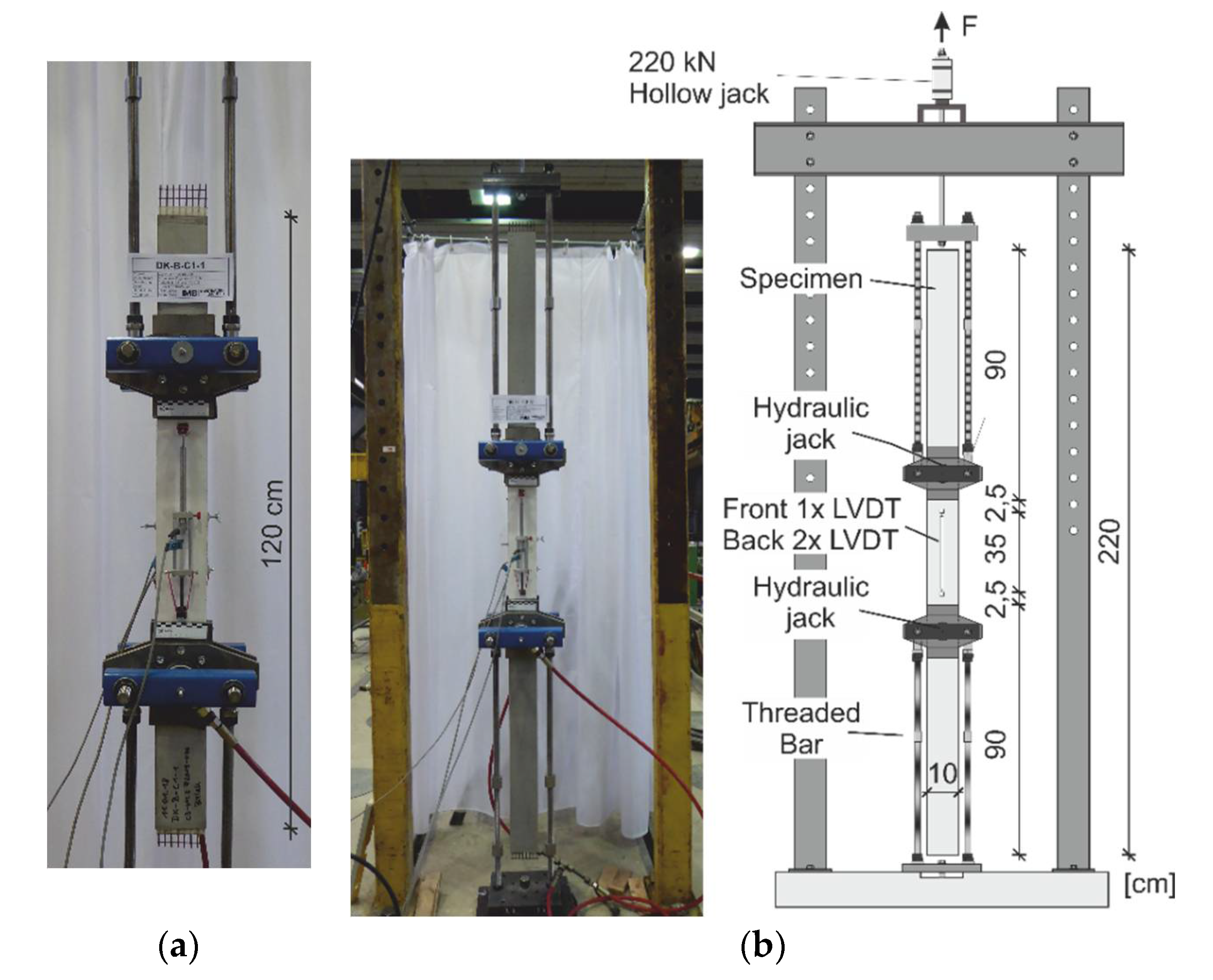
2.3. Tensile Tests
2.4. Double-Sided-Pullout Tests
2.5. Incremental Inverse Analysis Procedure
2.6. Simulation of Stress-Strain Behavior of Cracked Composite Specimen
3. Results
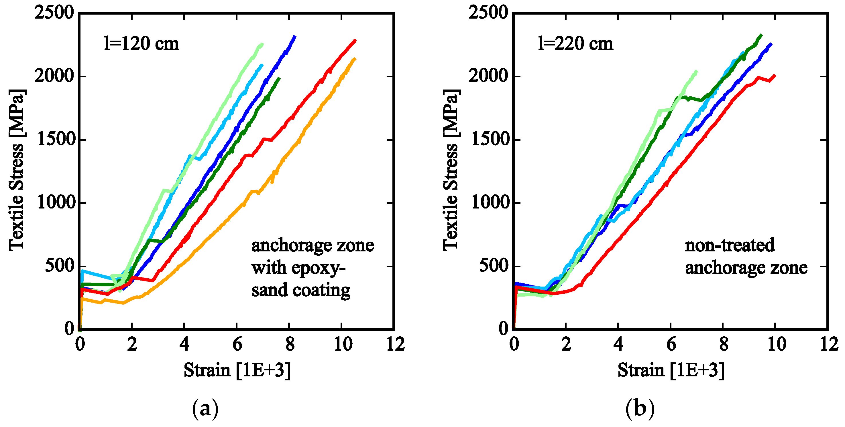
3.1. Uniaxial Tensile Tests
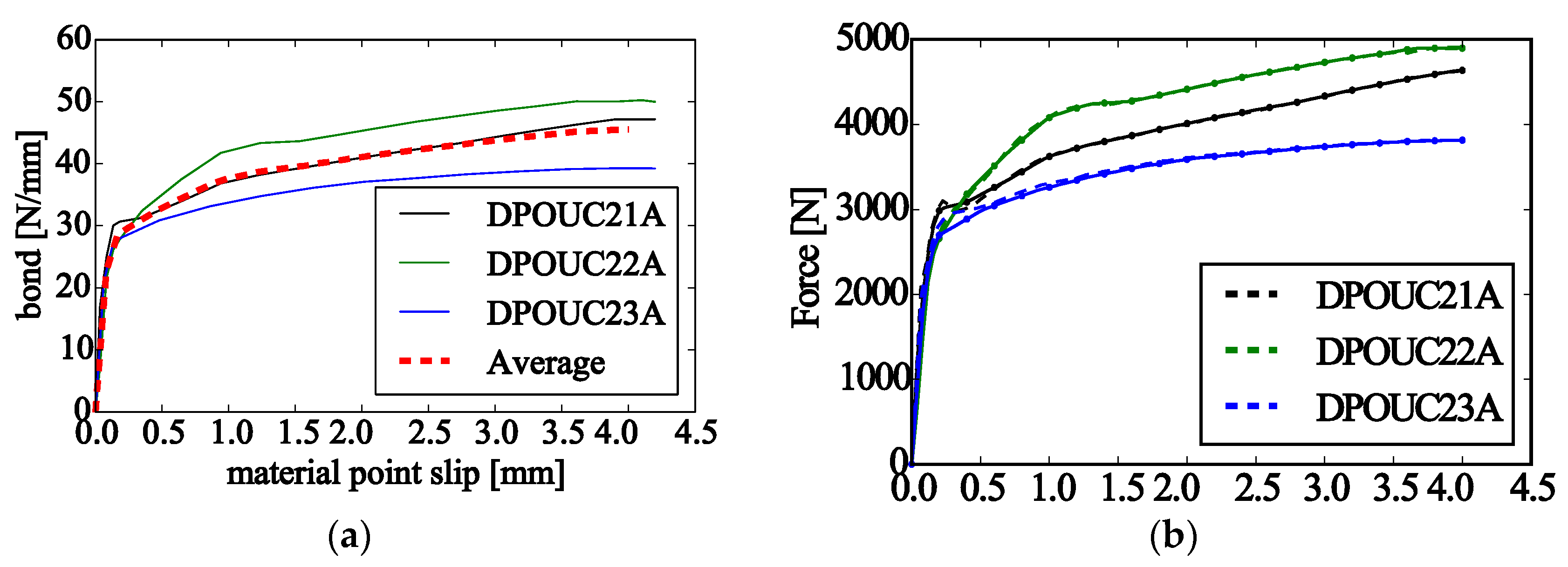
3.2. Double-Sided Pullout and Calibration of Bond-Slip Law
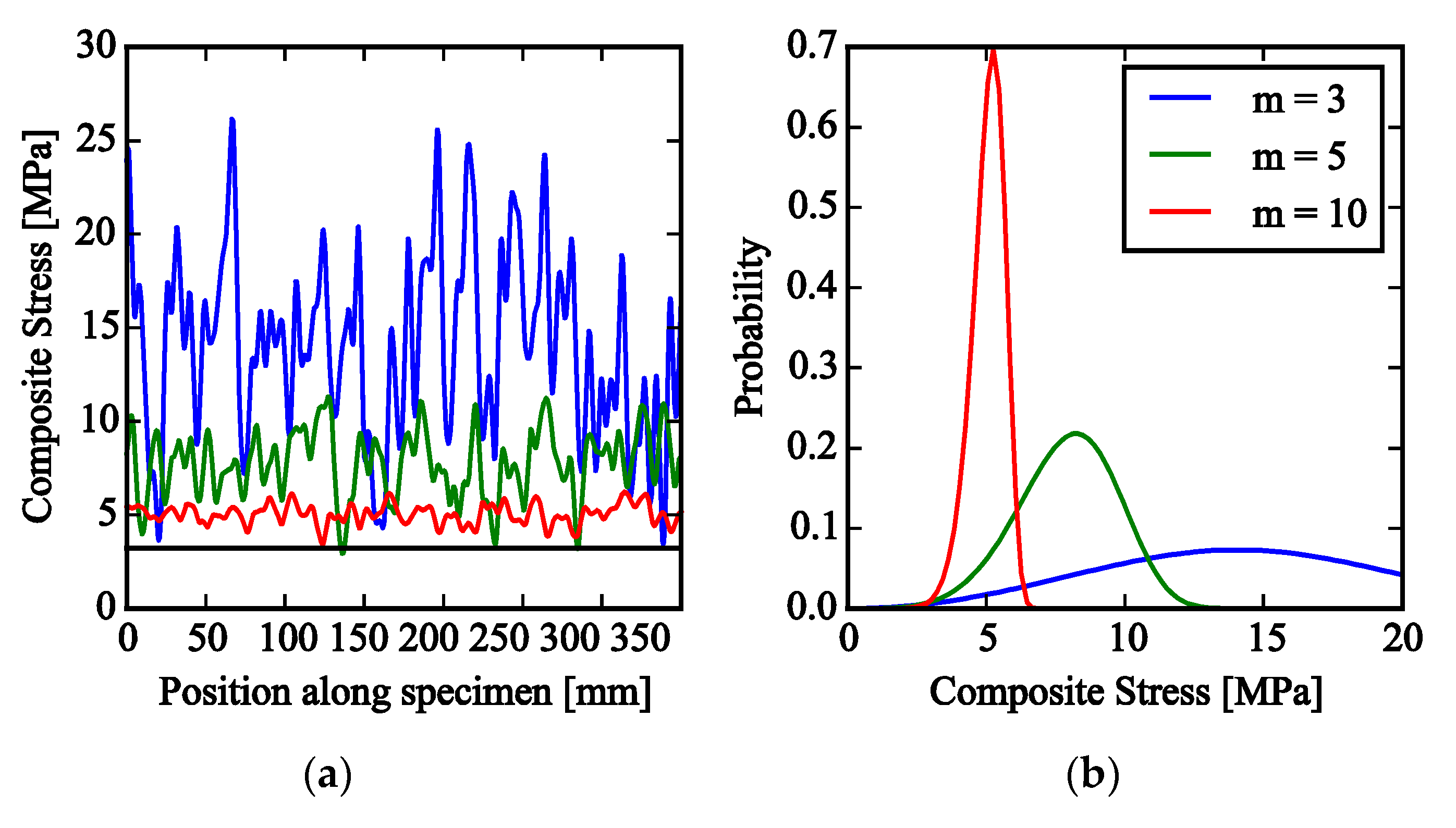
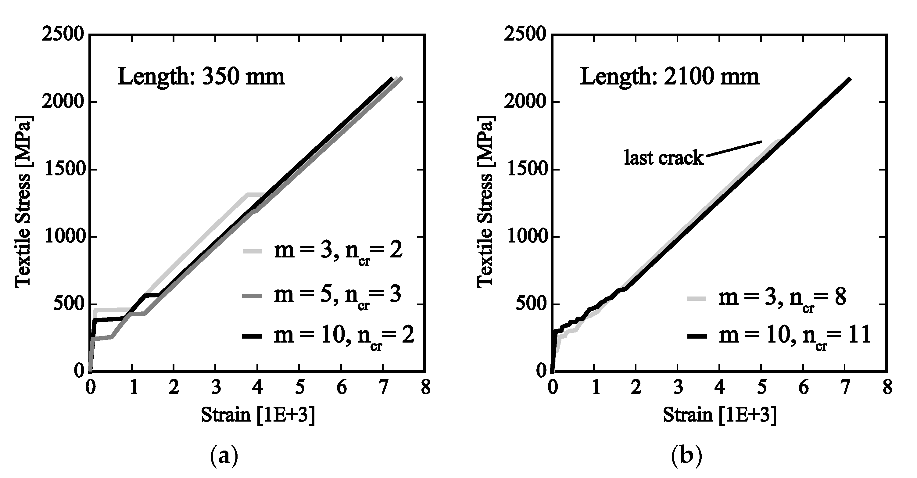
3.3. Simulation of Tensile Test with Random Matrix Strenght
4. Discussion and Conclusions
Author Contributions
Acknowledgments
Conflicts of Interest
References
- Bielak, J.; Hegger, J.; Chudoba, R. Towards Standardization: Testing and Design of Carbon Concrete Composites. In High Tech Concrete: Where Technology and Engineering Meet; Hordijk, D.A., Luković, M., Eds.; Springer International Publishing: Cham, Switzerland, 2017; pp. 313–320. [Google Scholar]
- TUDAG. Verfahren zur Verstärkung von Stahlbeton mit TUDALIT (Textilbewehrter Beton), 43-1.31.10-25/16; DIBT—Deutsches Institut für Bautechnik: Berlin, Germany, 2016. [Google Scholar]
- Schütze, E.; Bielak, J.; Scheerer, S.; Hegger, J.; Curbach, M. Uniaxial tensile test for carbon reinforced concrete with textile reinforcement. Beton Stahlbetonbau 2018, 113, 33–47. [Google Scholar] [CrossRef]
- Brameshuber, W.; Hinzen, M.; Dubey, A.; Peled, A.; Mobasher, B.; Bentur, A.; Aldea, C.; Silva, F.; Hegger, J.; Gries, T.; et al. Recommendation of RILEM TC 232-TDT: Test methods and design of textile reinforced concrete—Uniaxial tensile test: Test method to determine the load bearing behavior of tensile specimens made of textile reinforced concrete. Mater. Struct. 2016, 49, 4923–4927. [Google Scholar] [CrossRef]
- Bielak, J.; Li, Y.; Hegger, J.; Chudoba, R. Numercial and Experimental Characterization of Anchorage Length for Textile Reinforced Concrete. In Strain-Hardening Cement-Based Composites; Mechtcherine, V., Slowik, V., Kabele, P., Eds.; Springer: Dordrecht, The Netherlands, 2017; pp. 409–417. [Google Scholar]
- Li, Y.; Bielak, J.; Hegger, J.; Chudoba, R. An incremental inverse analysis procedure for identification of bond-slip laws in composites applied to textile reinforced concrete. Compos. Part B Eng. 2018, 137, 111–122. [Google Scholar] [CrossRef]
- Li, Y.; Chudoba, R.; Bielak, J.; Hegger, J. A modelling Framework for the Tensile Behavior of Multiple Cracking Composite. In Strain-Hardening Cement-Based Composites; Mechtcherine, V., Slowik, V., Kabele, P., Eds.; Springer: Dordrecht, The Netherlands, 2017; pp. 418–426. [Google Scholar]

| Batch No. (Age) | Bending Tensile Strength [MPa] | CoV [%] | Compressive Strength [MPa] | CoV [%] |
|---|---|---|---|---|
| 1 (27 d) | 4.66 | 3.9 | 88.55 | 3.3 |
| 2 (27 d) | 5.03 | 6.9 | 93.80 | 4.0 |
| 3 (28 d) | 4.63 | 2.6 | 96.80 | 5.2 |
| Anchorage w. Additional Coating (120 cm) | Non-Treated Anchorage (220 cm) | ||||||
|---|---|---|---|---|---|---|---|
| σt,u | E (IIb) | No. Cracks 1 | σt,u | E (IIb) | No. Cracks 1 | ||
| No. | [MPa] | [MPa] | [-] | No. | [MPa] | [MPa] | [-] |
| 1 | 2325 | 328,800 | 2 | 1 | 2264 | 235,500 | 3 |
| 2 | 2100 | 315,300 | 2 | 2 | 2198 | 271,200 | 2 |
| 3 | 1991 | 303,100 | 2 | 3 | 2335 | 224,800 | 3 |
| 4 | 2265 | 336,500 | 2 | 4 | 2050 | 291,400 | 2 |
| 5 | 2296 | 248,000 | 4 | 5 | 2013 | 287,500 | 3 |
| 6 | 2147 | 295,800 | 3 | 6 | 2179 | - | 4 |
| Mean | 2160 | 304,600 | - | Mean | 2173 | 262,100 | - |
| COV | 5.8% | 10.4% | COV | 5.7% | 11.6% | ||
Publisher’s Note: MDPI stays neutral with regard to jurisdictional claims in published maps and institutional affiliations. |
© 2018 by the authors. Licensee MDPI, Basel, Switzerland. This article is an open access article distributed under the terms and conditions of the Creative Commons Attribution (CC BY) license (https://creativecommons.org/licenses/by/4.0/).
Share and Cite
Bielak, J.; Li, Y.; Hegger, J.; Chudoba, R. Characterization Procedure for Bond, Anchorage and Strain-Hardening Behavior of Textile-Reinforced Cementitious Composites. Proceedings 2018, 2, 395. https://doi.org/10.3390/ICEM18-05224
Bielak J, Li Y, Hegger J, Chudoba R. Characterization Procedure for Bond, Anchorage and Strain-Hardening Behavior of Textile-Reinforced Cementitious Composites. Proceedings. 2018; 2(8):395. https://doi.org/10.3390/ICEM18-05224
Chicago/Turabian StyleBielak, Jan, Yingxiong Li, Josef Hegger, and Rostislav Chudoba. 2018. "Characterization Procedure for Bond, Anchorage and Strain-Hardening Behavior of Textile-Reinforced Cementitious Composites" Proceedings 2, no. 8: 395. https://doi.org/10.3390/ICEM18-05224
APA StyleBielak, J., Li, Y., Hegger, J., & Chudoba, R. (2018). Characterization Procedure for Bond, Anchorage and Strain-Hardening Behavior of Textile-Reinforced Cementitious Composites. Proceedings, 2(8), 395. https://doi.org/10.3390/ICEM18-05224