Abstract
Prefabricated and non-load bearing sandwich façade elements were developed using Textile Reinforced Reactive Powder Concrete (TRRPC) along with low density Foamed Concrete (FC) and Glass Fiber Reinforced Polymer (GFRP) continuous connecting devices. Four-point bending tests were performed on large-scale TRRPC sandwich element beams to characterize the structural performance, which included the flexural capacity, level of composite action, resulting deformation, crack propagation and failure mechanisms. Optical measurements based on Digital Image Correlation (DIC) were taken simultaneously to enable a detailed analysis of the underlying composite action. The structural behavior of the developed elements was found to be highly dependent on the stiffness and strength of the connectors to ensure composite action between the two TRRPC panels.
1. Introduction
New materials have recently emerged on the market enabling the thickness and weight reduction of precast concrete façade elements. Examples of such innovative materials include alternative reinforcements to conventional steel rebar, e.g., textile reinforcement, and high-performance concretes, e.g., ultra-high-performance concrete (UHPC) or reactive powder concrete (RPC). UHPC/RPC has successfully been used in façades as this type of high performance concrete demonstrates extraordinary high strength and durability [1,2,3]. In the EC funded project SESBE (Smart Elements for Sustainable Building Envelopes), textile reinforcement was added to RPC, namely Textile Reinforced Reactive Powder Concrete (TRRPC), to additionally improve the post-cracking behavior of the cementitious matrix. This high-performance composite material was incorporated in prefabricated and non-load bearing sandwich façade elements along with low density Foamed Concrete (FC) and Glass Fiber Reinforced Polymer (GFRP) continuous connecting devices.
This paper presents the experimental characterization of the flexural behavior of the developed TRRPC sandwich elements. Four-point bending tests were conducted on large-scale TRRPC elements according to a quasi-static loading scheme to gain an understanding of the associated flexural capacity, level of composite action, deformations, crack propagation and failure mechanisms. Optical deformation measurements using Digital Image Correlation (DIC) were taken to obtain a more detailed analysis of the flexural behavior in relation to the deflection shape and relative displacement between the TRRPC panels, so-to-say the composite action. DIC is an accurate non-contact measurement technique which has been proven to be an applicable method for measuring e.g., crack opening, fracture behavior and interfacial debonding properties of concrete [4,5]. Results from the tests and analysis, including using DIC, are presented and discussed primarily for two beam specimens with either single or double connector configurations.
2. Materials and Methods
2.1. Element Design
The façade elements developed in this project are prefabricated concrete sandwich elements, which are intended to be attached to the main load-bearing structure by means of an anchorage system. Such elements are often categorized as architectural concrete cladding and have aesthetic, structural and isolating functions [6]. The developed elements, further described in [7,8], were designed to span vertically between two floor storeys and as such have a significant surface area (7–10 × 2.7–3.0 m) and weight (2–5 ton). The façade elements are essentially a combination of two TRRPC panels, whereby the outer and inner panels have a thickness of 25 mm. The TRRPC panels are separated by a 150 mm thick FC insulating core material and attached with GFRP connecting devices.
2.2. Applied Materials
TRRPC applied in this project consisted of a RPC reinforced by two layers of an epoxy coated carbon textile grid (Solidian GRID Q85/85-CCE-21). An RPC formulation with higher amounts of supplementary cementitious materials (SCMs) was developed for use in prefabricated concrete façades. RPC is a variant of ultra-high-performance concrete (UHPC) which has a maximum aggregate size of 2 mm or smaller. It is characterized as having a compressive strength above 120 MPa and a very low percentage of capillary pores. Further information pertaining to the concrete mix development can be found in [9].
The core of the sandwich element was made of FC, which is a lightweight cementitious material applied as a thermally insulating material. It principally consists of a combination of cement, sand, water, foam, Quartzene® and short polypropylene fibers. A detailed description of this material can be found in [10].
Truss-like connectors made of GFRP, produced by Mostostal Warszawa S.A., were incorporated in the sandwich element to enable sufficient composite action between the outer and inner TRRPC panels. The base material of the connectors consists of a pultruded bar of E-glass fibers impregnated with an epoxy resin and wound with helical ribs on the surface. The bars were formed into a zig-zag shape in a half-cured state and then cured into the final state in a subsequent step. Two connector configurations were investigated in this study, namely single (S) and double (D). The double connector consists of two single connectors which are mirrored with respect to the longitudinal direction and connected by plastic tie straps at intersecting points. A detailed account of the structural performance of these connectors can be found in [7].
2.3. Four-Point Bending Tests
Four-point bending tests were conducted on full-length beams of TRRPC-FC sandwich elements, as shown in Figure 1. The results generated by these tests are also useful in determining the bending stiffness, cracking moment and bending moment resistance of the developed elements. Test specimens consisted of two TRRPC panels with a nominal thickness of 25 mm and a FC insulation of 150 mm. The length and width of the specimen was set to 2.5 m and 0.6 m. Both TRRPC panels were reinforced by two carbon textile grid layers connected to each other by distance spacers. The distance between the layers was 10 mm and the cover thickness of the outer layer was 5 mm. Two rows of connectors were placed longitudinally in each specimen at an edge distance of 100 mm, center-to-center spacing of 400 mm, and embedment depth of 10 mm. In this project, three specimens of both single and double configurations were tested, denoted as S-X (S-1 to S-3) and D-X (D-1 to D-3), respectively.

Figure 1.
Schematic of four-point bending test set-up and specimen geometry.
The specimens were placed on two end supports, with a center distance, L, of 2.4 m. The specimens were loaded by two upper line loads each applying a load of P/2, which were 0.8 m apart. The tests were performed in a servo hydraulic testing machine and the load was applied quasi-statically in displacement control with a rate of 5 mm/min. The mid-span deflection of the element was measured using a linear variable displacement transducer (LVDT) with a measuring range of 100 mm and a relative error less than 1.5%. The rated capacity of the load cell was 100 kN with a relative error within 1%, while the displacement and the load were recorded at a rate of 20 Hz.
2.4. Digital Image Correlation (DIC)
Optical deformation measurements were performed along one side of the element to capture the displacements of both TRRPC panels. The image acquisition was performed using the optical system ARAMIS 12M and the evaluation was executed in GOM Correlate Professional V8 [11]. The system uses a measurement technique based on Digital Image Correlation (DIC). The system was set up as two individual 2D measurements (measuring area 1.4 × 1.0 m2), each camera covering half the beam, with a small overlap at the center. The coordinate measurement accuracy was approximately 3 μm and the image capture frequency was 1 Hz.
Measuring points were defined on the upper and lower TRRPC panels every 200 mm to capture the localized displacement at each of these points during testing as indicated in Figure 2. The relative displacement between the panels was represented as the shear angle between the panels as measured in the optical system. A shear angle was calculated at 13 locations along the beam, which corresponds to the change in angle defined by three reference points, namely UN, LN and LN + 1, where the index N refers to the reference point number.

Figure 2.
Image from the optical system of the left side of the beam (S-1).
3. Results
3.1. Four-Point Bending Results
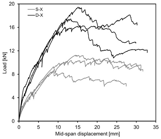
The bending behavior of the two specimen configurations is shown in Figure 3 in terms of load versus mid-span displacement from LVDT measurements. It can be observed that the initial stiffness of the composite element is less for the single connector configuration compared to the double connector configuration. First cracking also occurs at a slightly lower load level for the S-X specimens, which is followed by a loss of stiffness. Upon reaching the maximum load, the S-X specimens undergo a significant loss of stiffness depicted by a nearly horizontal plateau which is believed to signify connector pull-out. In relation to the specimens with double connectors, D-X, the specimens with single connectors are shown to exhibit approximately 40% of the experimental bending stiffness in the uncracked stage and 57% of the load resistance. An interesting observation to note is that all samples displayed a relatively ductile failure even though both RPC and GFRP are brittle materials.

Figure 3.
Load versus mid-span displacement for single and double connector configurations.
3.2. Optical Measurements
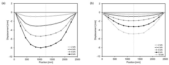
From the optical measurements, a more detailed analysis of the flexural behavior in relation to the deflection shape and relative displacement between the panels was enabled. The deflection shape of the lower panel was evaluated at different load levels for both connector configurations, as exemplified for S-1 and D-1 in Figure 4. It can be observed that specimen D-1 exhibits smaller deformations and a more symmetric deflection shape compared to S-1. For instance, at a load level of 4 kN, which refers to the first cracking load for S-1, the maximum displacement noted for S-1 is 3.1 mm which is more than three times that observed for D-1 (0.9 mm). When approaching the maximum load for S-1 (8 kN), the maximum displacement for S-1 (8.0 mm) is slightly more than double that yielded for D-1 (3.2 mm).

Figure 4.
Deflection shape of the lower panel at different load levels for specimens (a) S-1 and (b) D-1.
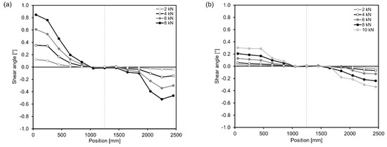
The shear angle distribution analyzed from the optical measurements is depicted in Figure 5 for S-1 and D-1. It can be noted that the shear angle is approximately zero at the middle of the specimen and increases in absolute values towards the ends. D-1 provides more composite action, as the shear angle is smaller, compared to S-1 at the same load level.

Figure 5.
Shear angle between the lower and upper panels along specimens (a) S-1 and (b) D-1.
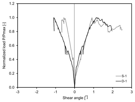
The development of the shear angles at the ends of the beams, i.e., 50 mm and 2400 mm, are plotted against the normalized load, being the ratio between the load and the maximum load (P/Pmax) for S-1 and D-1 in Figure 6. Generally, the shear angle gradually increased at the beam ends due to increased loading. As well, the shear angle developed in a more symmetrical manner for D-1. The shear angle increased between 30% and 40% of the maximum load, which is thought to correspond to first cracking. After this point, the load continued to increase until reaching the maximum load marked by a ratio of 1.0. Subsequently, the load either remained relatively constant or decreased followed by further development of the shear angle at one end of the beam. This observed behavior is thought to be a consequence of a connector failure occurring around the maximum load, thus leading to lower longitudinal shear stiffness and increased relative displacements between the panels.

Figure 6.
Development of the shear angle at two beam ends for specimens S-1 and D-1.
4. Conclusions
Four-point bending testing was conducted on large-scale TRRPC-FC elements according to a quasi-static loading scheme to gain an understanding of the associated flexural capacity, level of composite action, deformations, crack propagation and failure mechanisms. The structural behavior of the developed TRRPC-FC sandwich elements was found to be highly dependent on the stiffness and strength of the GFRP connectors to ensure composite action between the two TRRPC panels. The failure of the sandwich elements was mainly attributed to the connector capacity, which was also greatly influenced by the initiation and progression of connector pull-out from the panels. The difference can mainly be associated to the stiffness, such that the specimens with double connectors exhibit smaller deflections due to more composite action.
The optical measurements based on DIC proved to be advantageous to measure displacements along the length of the TRRPC panels during testing, which were subsequently applied to quantify the relative longitudinal displacement between the panels. A deeper insight on the composite action of the developed sandwich elements could be gained through this method.
Author Contributions
F.M., M.U. and W.P.N. designed and produced the sandwich elements; F.M. designed and performed the four-point bending tests; W.P.N. and F.M. analyzed the experimental results; W.P.N. and F.M. wrote the paper.
Acknowledgments
The presented research was made possible with the support of the European Community’s Seventh Framework Programme under Grant Agreement no. 608950 (SESBE). Further SESBE research project information can be found here: www.sesbe.eu.
Conflicts of Interest
The authors declare no conflict of interest.
References
- Miccoli, L.; Fontana, P.; Silva, N.; Klinge, A.; Cederqvist, C.; Kreft, O.; Qvaeschning, D.; Sjöström, C. Composite UHPC-AAC/CLC facade elements with modified interior plaster for new buildings and refurbishment. Materials and production technology. J. Facade Des. Eng. 2015. 3, 91–102. [CrossRef]
- Ghoneim, G.; El-Hacha, R.; Carson, G.; Zakariasen, D. Precast Ultra High Perfromance Fibre Reinforced Concrete Replaces Stone And Granite On Building Façade. In Proceedings of the Third International Fib Congress Incorporating the PCI Annual Convention and Bridge Conference 2010, Washington, DC, USA, 29 May–2 June 2010; Precast Prestressed Concrete Institute (PCI): Chicago, IL, USA, 2010. [Google Scholar]
- Rebentrost, M.; Wight, G.; Fehling, E. Experience and applications of ultra-high performance concrete in Asia. In Proceedings of the 2nd International Symposium on Ultra High Performance Concrete, Kassel, Germany, 5–7 March 2008. [Google Scholar]
- Corr, D.; Accardi, M.; Graham-Brady, L.; Shah, S. Digital image correlation analysis of interfacial debonding properties and fracture behavior in concrete. Eng. Fract. Mech. 2007, 74, 109–121. [Google Scholar] [CrossRef]
- Skarzynski, L.; Kozicki, J.; Tejchman, J. Application of DIC technique to concrete—Study on objectivity of measured surface displacements. Exp. Mech. 2013. 53, 1545–1559.
- fib. fib Bulletin No. 74—Planning and Design Handbook on Precast Building Structures; fib: Lausanne, Switzerland, 1998. [Google Scholar]
- Flansbjer, M.; Honfi, D.; Vennetti, D.; Mueller, U.; Williams Portal, N.; Wlasak, L. Structural performance of GFRP connectors in composite sandwich façade elements. J. Facade Des. Eng. 2016, 4, 35–52. [Google Scholar] [CrossRef]
- Flansbjer, M.; Honfi, D.; Vennetti, D.; Portal, N.W.; Mueller, U.; Własak, L. Structural Concept of Novel RPC Sandwich Façade Elements with GFRP Connectors. In Proceedings of the 19th IABSE Congress, Stockholm, Sweden, 21–23 September 2016. [Google Scholar]
- Mueller, U.; Williams Portal, N.; Chozas, V.; Flansbjer, M.; Larazza, I.; da Silva, N.; Malaga, K. Reactive powder concrete for facade elements—A sustainable approach. J. Facade Des. Eng. 2016, 4, 53–66. [Google Scholar] [CrossRef]
- Silva, N.; Mueller, U.; Malaga, K.; Hallingberg, P.; Cederqvist, C. Foam concrete-aerogel composite for thermal insulation in lightweight sandwich facade elements. In Proceedings of the 27th Biennial National Conference of the Concrete Institute of Australia in Conjunction with the 69th RILEM Week, Melbourne, Australia, 30 August–2 September 2015; Concrete Institute of Australia: Sydney, Australia, 2015. [Google Scholar]
- GOM. GOM Correlate Manual Basic, GOM Optical Measuring Techniques; GOM mbH: Braunschweig, Germany, 2015. [Google Scholar]
Publisher’s Note: MDPI stays neutral with regard to jurisdictional claims in published maps and institutional affiliations. |
© 2018 by the authors. Licensee MDPI, Basel, Switzerland. This article is an open access article distributed under the terms and conditions of the Creative Commons Attribution (CC BY) license (https://creativecommons.org/licenses/by/4.0/).