Proceeding Paper

The Vibe of Skating; Design and Testing of a Vibro-Tactile Feedback System †

by
Arjen J. Jansen
*,
Marijke Dekker
and
Diederik van der Steen
Faculty of Industrial Design Engineering, Delft University of Technology, Landbergstraat 15, 2828 CE Delft, The Netherlands
*
Author to whom correspondence should be addressed.
Presented at the 12th Conference of the International Sports Engineering Association, Brisbane, Queensland, Australia, 26–29 March 2018.
Proceedings 2018, 2(6), 296; https://doi.org/10.3390/proceedings2060296
Published: 8 March 2018

Abstract

:
Providing athletes with real-time feedback on their performance is becoming common in many sports, also in speed skating. This research-by-design project aims at finding a tool that allows the speed skater to get real-time feedback on his performance. Speed skaters often mention a so-called “good feeling” when skating behind a better skater. It is the feeling nearly every speed skater is after when skating alone; skate with less power while maintaining the same speed and feeling of ease. A longer push-off phase at a constant cadence has proven to contribute to this ideal situation but is hard for the coach alone to influence this. Therefore, a system was designed that measures the skating cadence and challenges the skater to change his skating stroke by means of vibro-tactile feedback. Four subjects have tested the feedback system. From this test, we concluded that the system provides meaningful feedback towards changing the skating cycle.

1. Introduction

Speed skating has a long history in the Netherlands, partly explaining the research interest in this field. The speed of the skater is determined by both physics, physiology and psychology and can be increased by optimizing parameters in three domains; (1) muscular power generation; (2) efficiency of the power conversion system (energy transfer/transmission) and (3) reduction of resistance and friction. In the last domain, research efforts have led to drag reduction (aerodynamics of the suit, speed-strips) allowing the skater to go faster with the same power. From a bio-mechanics view point, speed skating itself consists of a rather complex and mutual dependent series of movements. This series of movements, executed in the right posture (i.e., knee angle) and combined with muscular power, determines the amount of muscular work for the final propulsion of the speed skater. Speed skaters say “they have found their stride” when they feel they have reached a state in which they can maintain a constant rhythm and are ‘in flow’.

2. Phases in the Skating Stroke

In general, three phases can be identified in a skating stroke: the gliding phase, the push-off phase and the repositioning phase [1] (see Figure 1). The starting point for the design phase in this project was determined by the assumptions that (1) the relation between the length of the push-off phase and the double support phase and (2) a constant rhythm are essential in the efficiency of skating. This can be explained by acknowledging the following aspects of the skating cycle [2,3]:
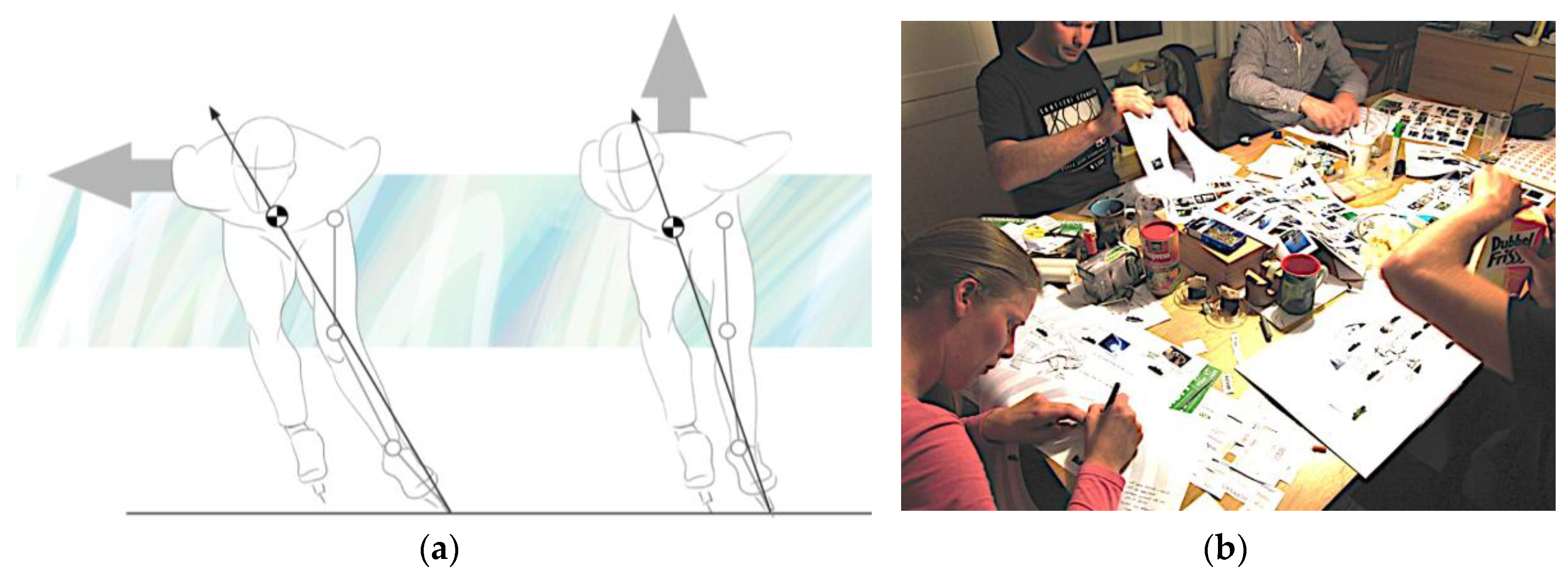
  • A longer push-off at one skate elicits a longer fall. A longer fall decreases the angle between the skate and the ice and therefore enables the skater to push-off more sideways instead of pushing up; i.e., the vertical component of the muscular force becomes smaller at increased angles (see Figure 2). The vertical force component creates a vertical displacement of the centre of mass (COM), therefore using the muscular work less efficient.
  • Shortening the double support phase makes the skating motion more efficient; the skaters mass is longer supported by one single skate, allowing him to push of harder. Shortening this phase can be achieved by positioning the skate later onto the ice, resulting in a longer fall.
  • A longer fall also results in a smaller knee angle of the new gliding skate. Reducing the knee angle helps the skater to reduce aerodynamic drag (reduction of frontal area), lower the COM and increase the work per stroke.
This assumption has further been examined in a ‘research-by-design project’ aiming at answering the following research questions: what type of feedback will support motor learning skills in skating? (Q1) How and when should this feedback be provided? (Q2) How can we effectively and efficiently measure the start and end-point of the different phases in skating? (Q3) How should the user interface be in order to be acceptable for a larger target group?

3. The Target Group

This project aimed at supporting amateur skaters who do not have access to a professional/personal coaching staff. In order to get direct input from the target group, a participatory design approach was followed [4] in a focus group setting. The focus group consisted of four amateur skaters from the target group (3 male/1 female, average age 35 years, twice weekly skate training, 20 years skating experience on average). From the focus group session, we learned that skaters would like to have feedback on: the waiting time to place their skate onto the ice (waiting longer allows you to make longer strokes), to what level their speed is constant, their posture (sit low), the sway (lateral movement during skating) and pressure distribution along the length of the skate. Furthermore, they want to have control over their own development in order to improve their skating technique. The sessions with the focus group also revealed the fact that they perceive skate training as a social event in which peer-feedback and peer-support is highly appreciated.

4. Providing Feedback to the User

For this project, we initially looked at three possible ‘channels’ over which we are able to provide the user with feedback; visually, auditory and tactile. Providing humans with feedback in a visual way is an accepted and widely used option; feedback can be offered in the focal vision or in the peripheral vision of the user. A disadvantage of this method is the effect of the higher cognitive load, resulting in increased response times [5,6,7]. The second most used channel for providing information to the use is the auditory channel. It can be used in case the visual channel is occupied or the use of the visual channel is excluded due to other reasons. Reaction times to auditory signals are low. Applications can be seen in rowing and karate and baseball [8,9,10]. Auditory feedback was also used in skating; Godbout [11] tested a phase-matching system that used sensor data from model skaters. Major drawback of this system is the lack of freedom for the skater to explore and discover his personal preferences in technique.
Tactile feedback is often referred to as one of the “neglected possibilities of communication” [12]. The most common way of tactile communication in sports is with use of vibro-tactile displays transferring vibrations to the wearers skin [13,14]. For intuitive stimuli, tactile communication has a relative low added cognitive load. This was also the reason to use tactile feedback in a gait rehabilitation device [15]. The skin is very good in the distinction of temporal variables at levels close to that of the auditory system i.e., by pulsing one vibro-tactile actuator (tactor) at a fixed location [16,17]. Tactile stimuli are even better at coding spatial information (direction); a stimulus at one side of the body is directly linked to a specific direction [18]. Combining spatial and temporal variables into spatio-temporal variables allows to create a tactile stimulus on the wearers skin emulating an apparent movement [19].

5. The Design Process: From Design Goal to User Test

The design process started with the following design goal; ‘Help skaters of a medium to advanced level improve their technique by challenging them to increase the length of the push-off via use of vibro-tactile stimuli.’ The design method taught at the Faculty of Industrial Design Engineering at Delft University now prescribes a process in which successive diverging and converging design steps, the so-called ‘creative diamonds’, lead to a number of concept designs [20]. These concepts are assessed and ranked based on a predefined set of design criteria. The most valuable concept is then selected to be embodied into a prototype for user testing. We used a design method called ‘Protosketching’ [21] to explore and test the various elements of the tactile feedback system and designed and built a prototype to be tested by users.

5.1. Prototype and User Test

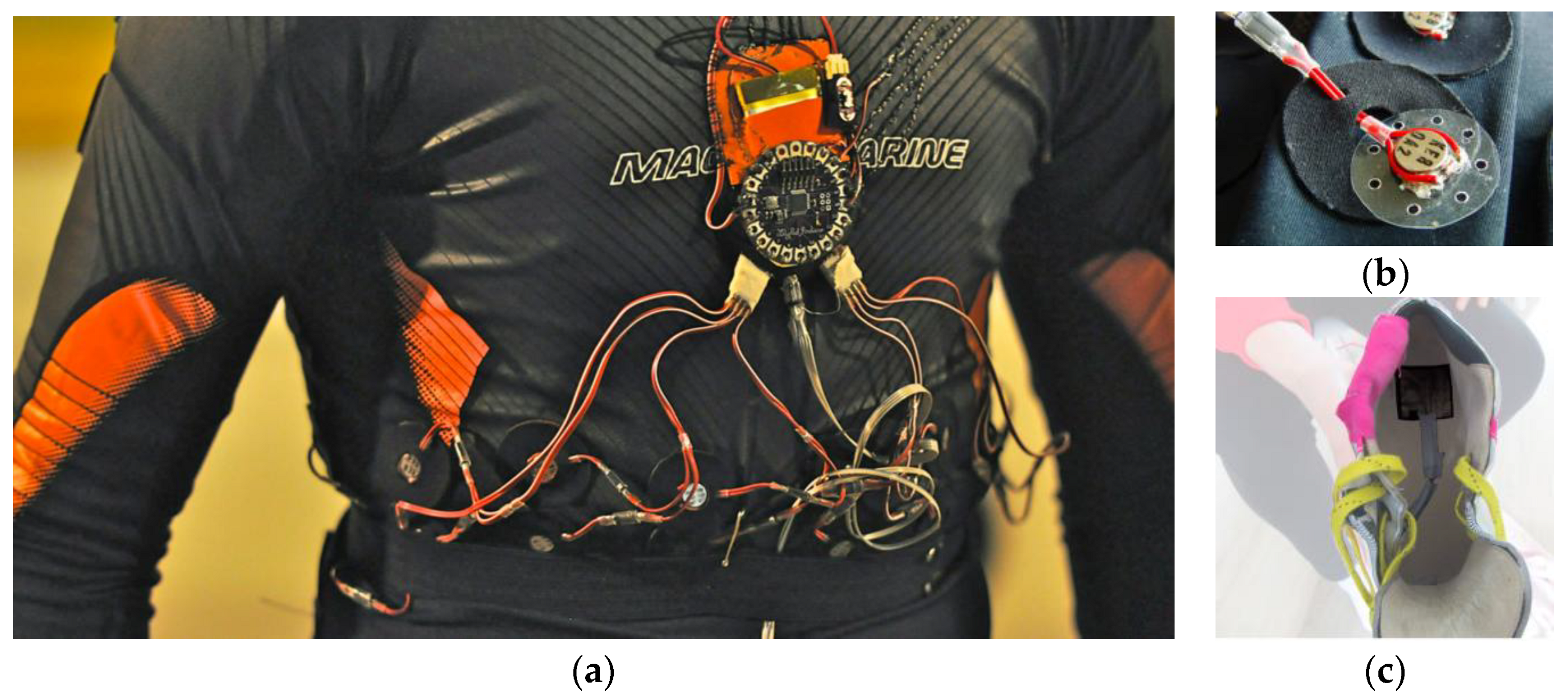
The prototype used a battery powered LilyPad Arduino board and eight tactors (vibro-tactile elements, see Figure 3b) mounted to a sports top made of stretching material (see Figure 3a). Two pressure sensors (see Figure 3c) in each skate are wirelessly connected to the LilyPad board. The controls for the system are placed near the wrist. In addition to the tactors, a series of LED’s was mounted at the belt, facing backwards and flashing in sync with the tactors. The LED’s allowed the researcher (when skating behind the subject) to see the vibro-tactile pattern and assess the experiment.
Testing of this prototype was performed with four users. The goal of the user test was to get qualitative feedback on the prototype. The subjects were invited individually to a skating venue (400 m ring). After connecting and testing the prototype, the system was briefly explained and what sensations to expect from it. At the ice, first the timing values of the system had to be set. Next, the skater was asked to skate at a moderate speed while attempting to follow the predefined rhythm of the vibro-tactile pattern. Initial timings of the stroke then were changed according the comments of the skater until the timing matched the current length of his/her pattern. After that, the duration of the pattern was increased in order to challenge the skater to elongate the push-off phase while maintaining the same speed.

5.2. Results

The user test provided valuable insights into the interactions with the system. The participants expressed to be able to feel the rhythm of the vibro-tactile pattern but initially found it hard to ‘pick it up’. By observing the LED on the back of the skaters and their skating pattern, it was found that the skaters are able to skate in the rhythm of the provided pattern; the skater pushed off at the moment the LED turned on and positioned the gliding skate at the moment it turned off. All four subjects were able to adjust their skating pace (increase the length of the push-off phase) by using this system.
Some statements from the participants: “I am getting more sensitive for the vibrations by the way.” and “At the start of the session I was continuously waiting for it to come but after a while you know where to expect it coming and feel it much faster”.

6. Final Design Proposal

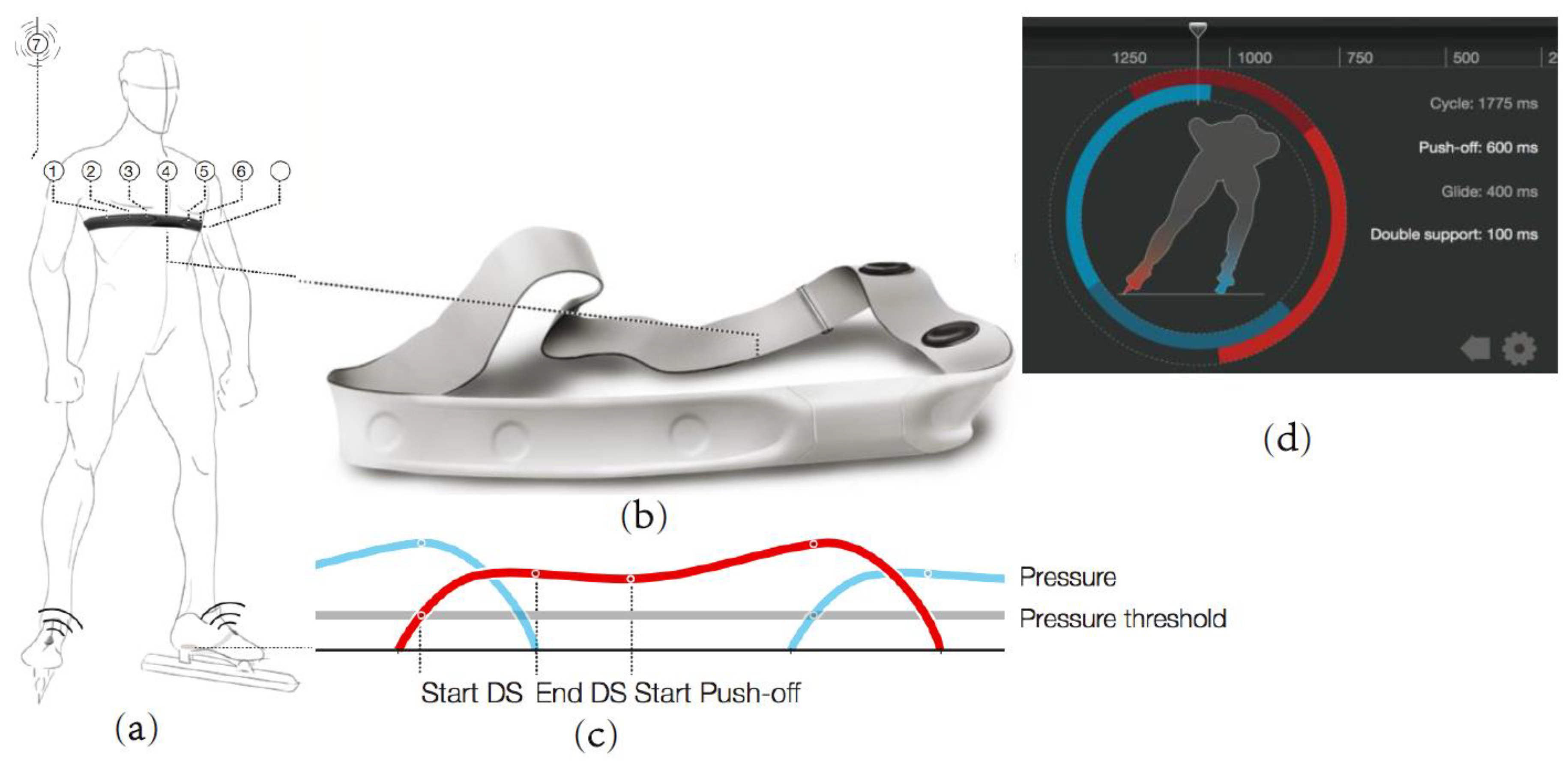
The final design proposal provides feedforward of the skating cycle rhythm and feedback on the double support phase. The tactile feedback system is integrated in a band around the skater’s chest (see Figure 4a,b), which connects to a set of wireless sensors. The start of the double support phase is defined by detecting a pressure increase at the heel of one skate while the other skate is still in the push-off phase (see Figure 4c). The rhythm is coded by a vibro-tactile pattern which starts when the push-off is set to start and stops when the double support phase begins. A push-off with the right skate starts at tactor nr. 1 and ends at tactor nr. 7 (and vice versa for the other skate). This pattern provides the feedforward with the time to start and end, but also with the speed of the pattern helping skaters to anticipate on how fast to push-off. When the skate is placed too early relative to the set pattern, the last (one or two) tactors will not vibrate, but the rhythm does not change. It is not only feedback, but also a little challenge to get the pattern to reach the end. Tests showed this to work well, but when the skater needs to swerve in front of another skater, it was impossible to get back to the rhythm. In this case (early placement of > 300 ms), the pattern will go to the glide phase immediately. During the glide phase, the middle tactor will pulse once to let the skater know the pattern is still there and the push-off will start soon.

7. Conclusion and Discussion

This paper has presented a research-by-design approach towards a user friendly vibro-tactile feedback system for skaters. The results of the user test allowed for general, qualitative insights in the use of the system. As an answer to the first research question, we concluded the system provides meaningful feedback when changing the skating cycle. Measuring the start- and end-point (answer to Q2) is successfully achieved by using pressure sensors mounted in the shoe of the skate. The solution for the user interface (Q3) is presented (see Figure 4d) but not tested. Further software development should lead to an improved user experience; the system should be able to detect when the skater is taking a curve or resting and act accordingly.

Acknowledgments

We kindly thank O’sports, Otto den Braver for his guidance and support during the project.

Conflicts of Interest

The authors declare no conflict of interest. The funding sponsors had no role in the design of the study; in the collection, analyses, or interpretation of data; in the writing of the manuscript, and in the decision to publish the results. The subjects in this research have given true voluntary informed consent.

References

  1. Boer, R.W. de; Ettema, G.J.C.; van Gorkum, H.; de Groot, G.; van Ingen Schenau, G.J. A geometrical model of speed skating the curves. J. Biomech. 1988, 21, 445–450. [Google Scholar] [CrossRef]
  2. Bilodeau, E.A.; Bilodeau, I.M. Motor-skills learning. Ann. Rev. Psychol. 1961, 12, 243–280. [Google Scholar] [CrossRef]
  3. Fintelman, D.M.; den Braver, O.; Schwab, A.L. A simple 2-dimensional model of speed skating which mimics observed forces and motions. In Proceedings of the Multibody Dynamics 2011, ECCOMAS Thematic Conference, Brussels, Belgium, 4–7 July 2011. [Google Scholar]
  4. Stappers, P.J.; Sleeswijk Visser, F. Bringing participatory design techniques to industrial design engineers. In Proceedings of the Engineering and Product Design Education Conference, NewCastle, UK, 13–17 September 2007; pp. 117–122. [Google Scholar]
  5. Mistry, P.; Maes, P. SixthSense: A wearable gestural interface. In Proceedings of the SIGGRAPH ASIA ’09 ACM SIGGRAPH ASIA 2009 Sketches, Yokohama, Japan, 16–19 December 2009. [Google Scholar]
  6. Money, K. Theory Underlying the Peripheral Vision Horizon Device; DTIC: Fort Belvoir, VA, USA, 1982. [Google Scholar]
  7. Leibowitz, H.; Dichgans, J. The Ambient Visual System and Spatial Orientation. Spatial Disorientation in Flight: Current Problems; AGARD CP-287; Perdriel, G., Benson, A.J., Eds.; Technical Editing and Reproduction Ltd.: London, UK, 1980. [Google Scholar]
  8. Schaffert, N.; Mattes, K.; Effenberg, A. A sound design for acoustic feedback in elite sports. In Auditory Display; Springer: Berlin/Heidelberg, Germany, 2010; pp. 143–165. [Google Scholar]
  9. Takahata, M.; Shiraki, K.; Sakane, Y.; Takebayashi, Y. Sound feedback for powerful karate training. In Proceedings of the 2004 Conference on New Interfaces for Musical Expression, Shizuoka, Japan, 3–5 June 2004. [Google Scholar]
  10. Pijnappel, S. 2012. Available online: http://sebastiaanpijnappel.com/wearable-coach/ (accessed on 11 October 2017).
  11. Godbout, A.; Boyd, J.E. Corrective sonic feedback for speed skating: A case study. In Proceedings of the International Conference on Auditory Display, Washington, DC, USA, 9–15 June 2010. [Google Scholar]
  12. Geldard, F.A. Some neglected possibilities of communication. Science 1960, 131, 1583–1588. [Google Scholar] [CrossRef] [PubMed]
  13. Van Erp, J.B.F.; Saturday, I.; Jansen, C. Application of tactile displays in sports: Where to, how and when to move. In Proceedings of the Conference on EuroHaptics, Paris, France, 3–6 July 2006. [Google Scholar]
  14. Spelmezan, D.; Jacobs, M.; Hilgers, A.; Borchers, J. Tactile motion instructions for physical activities. In Proceedings of the SIGCHI Conference on Human Factors in Computing Systems, Boston, MA, USA, 4–9 April 2009. [Google Scholar]
  15. Watanabe, J.; Ando, H. Pace-sync shoes: Intuitive walking-pace guidance based on cyclic vibro-tactile stimulation for the foot. Virtual Real. 2010, 14, 213–219. [Google Scholar] [CrossRef]
  16. Erp, V.; Jan, B. Tactile Torso Display as Countermeasure to Reduce Night Vision Goggles Induced Drift; DTIC: Fort Belvoir, VA, USA, 2003. [Google Scholar]
  17. Hale, K.S.; Stanney, K.M. Deriving haptic design guidelines from human physiological, psychophysical, and neurological foundations. IEEE Comput. Graph. Appl. 2004, 24, 33–39. [Google Scholar] [CrossRef] [PubMed]
  18. Van Veen, H.; van Erp, J. Tactile information presentation in the cockpit. In Haptic Human-Computer Interaction; Springer: Berlin, Germany, 2001; pp. 174–181. [Google Scholar]
  19. Geldard, F.A.; Sherrick, C.E. The Cutaneous “Rabbit”: A Perceptual Illusion. Science 1972, 178, 178–179. [Google Scholar] [CrossRef] [PubMed]
  20. Buijs, J.A. The Delft Innovation Method; Den Haag, Eleven International Publishing: Portland, OR, USA, 2012. [Google Scholar]
  21. Koskinen, I.; Mikkonen, J.; Eckoldt, K.; Hänninen, R.; Jiang, J.; Schultz, B.; Battarbee, K.; Suri, J.F. Protosketching: Sketching in Experience Prototyping. 2009. Available online: http://www2.uiah.fi/~ikoskine/recentpapers/submissions08/protosketching-submission-not-anon.pdf (accessed on 11 October 2017).
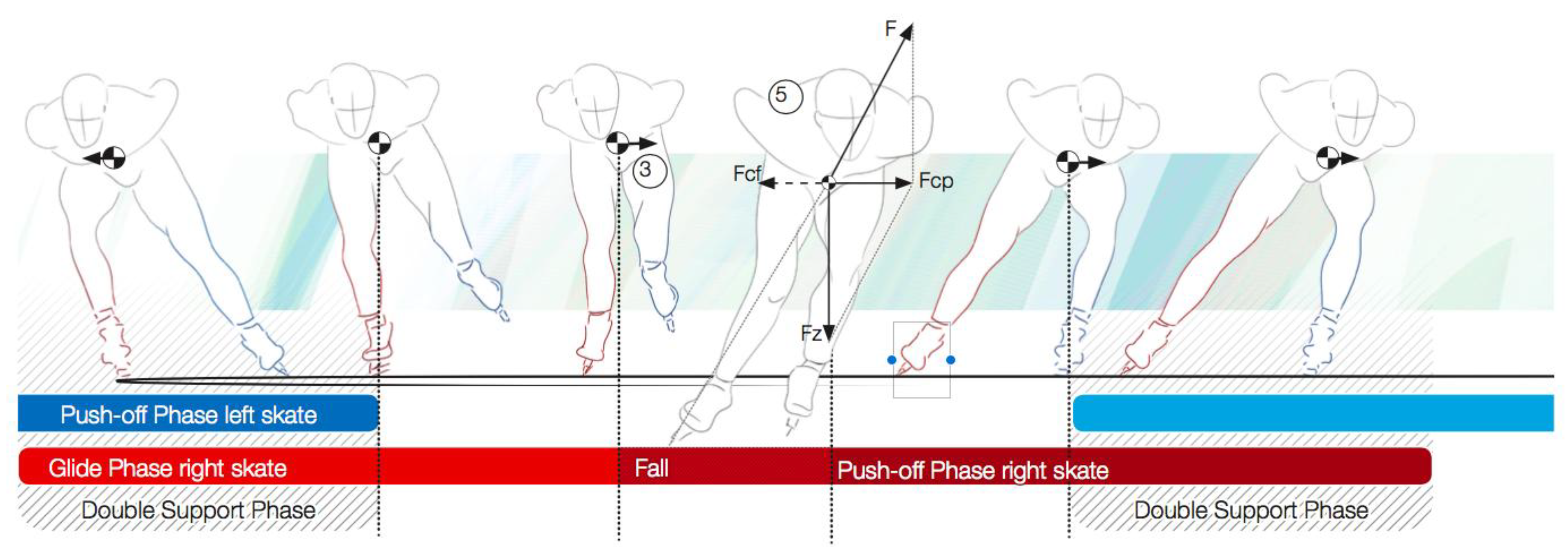
Figure 1. COM trajectory; 5 = the forces during the push-off phase; Fcf is the apparent sideward force.
Proceedings 02 00296 g001
Figure 2. (a) Fall in the push-off phase; the skater needs to fall sideways in order to push off (and not up); (b) Picture of the participants in the focus group session.
Proceedings 02 00296 g002
Figure 3. (a) The final prototype mounted on stretching apparel (b) mounting the vibro-tactile element (tactor) and (c) pressure sensor mounted inside the shoe of a skate.
Proceedings 02 00296 g003
Figure 4. (a) Skater wearing the chest band with tactors and microprocessor. (b) rendering of the final design proposal (c) signal from the pressure sensor in the skates (d) user-interface design for smart phone application.
Proceedings 02 00296 g004
Publisher’s Note: MDPI stays neutral with regard to jurisdictional claims in published maps and institutional affiliations.