Proceeding Paper

The Influence of the Grip Acceleration on Club Head Rotation during a Golf Swing †

1
Department of Mechanical Engineering, Graduate School of Science and Engineering, Doshisha University, 1-3, Tataramiyakodani, Kyotanabe-city Kyoto 610-0321, Japan
2
Faculty of Science and Engineering, Doshisha University, 1-3, Tataramiyakodani, Kyotanabe-city Kyoto 610-0321, Japan
3
Research Dept. II, Research & Development HQ, Sumitomo Rubber Industries Ltd., 1-1,2-Chome, Tsutsui-cho, Chuo-ku, Kobe 651-0071, Japan
*
Authors to whom correspondence should be addressed.
Presented at the 12th Conference of the International Sports Engineering Association, Brisbane, Queensland, Australia, 26–29 March 2018.
Proceedings 2018, 2(6), 241; https://doi.org/10.3390/proceedings2060241
Published: 11 February 2018

Abstract

:
Golfers aim to hit the golf ball correctly and maximize its displacement. It is necessary to predict shaft movement during a golf swing via simulation in order to determine the appropriate shaft for each individual golfer’s swing. Our previous study simulating golf club movement during the golf swing demonstrated 3D club movement via a finite element method simulation model with shaft flexibility. In this study, we added torque, taking into account the combination of grip acceleration and club head centroid, to the simulation model. In order to determine the influence of the torque, we then compared the measured and simulated results of shaft deflection and club head kinematics [HS (club head speed), Path (path angle), AA (attack angle), and FA (face angle)]. There was no significant torque influence for HS, AA, or shaft deflection. However, the Path and FA simulations were close to the measured values.

1. Introduction

The characteristics of drivers are especially important to golfers in order to correctly hit the golf ball and maximize its displacement. Several studies have reported the influence of golf shaft stiffness on club head kinematics experimentally [1,2]. Moreover, most studies on the prediction of golf club movement during the swing have used either multibody dynamics [3,4] or a finite element method (FEM) golf club model [5]. Our previous study simulating golf club movement during the golf swing demonstrated 3D club movement via a FEM simulation model with shaft flexibility [6,7]. However, the influence of grip acceleration on the club head during the golf swing was not investigated with this simulation model. Therefore, in this study, we added torque, taking into account the combination of grip acceleration and club head centroid, to the simulation model and investigated its influence.

2. Method

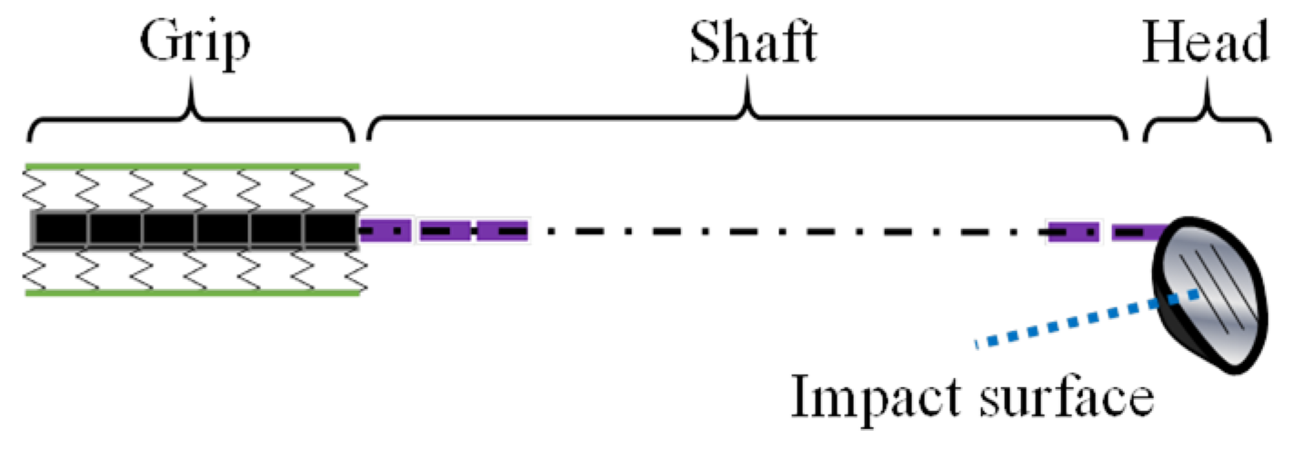
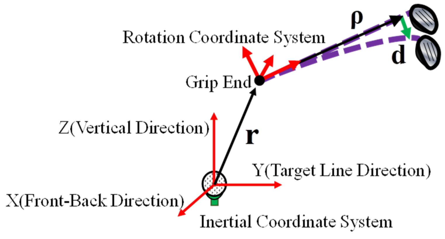
2.1. Model of Golf Club

In our previous study [6], we modelled a golf club using FEM with a Euler-Bernoulli beam-type element [8,9,10]. This model is divided into three parts: the grip, consisting of six elements, the shaft, consisting of 16 elements, and the club head (Figure 1). The grip elements are considered as a spring model.

2.2. Motion Equation

The motion equation for a golf club is determined by FEM with a Euler-Bernoulli beam-type element [5,8,9,10]. Then, for each element, the mass and stiffness matrices are calculated by energy law. For the club head, the inertia is determined by the club head’s mass and moment of inertia. The total mass matrix [M] and total stiffness matrix [K] are computed by combining the matrices of each element. The damping matrix [C] is computed using a modal damping matrix theory on the shaft elements. Finally, taking into account the potential energy of the golfer’s grip, our complete motion equation is obtained by:
[ M ] d ¨ + [ C ] d ˙ + [ K ] d = F
F indicates a generalized force and d indicates the displacement of the node and the angle of displacement. The generalized force for each node of the club elements is determined by a pendulum model (Figure 2). On this pendulum model, the origin point of the inertial coordinate system is put on a golf ball placed on a tee. We then define the rotation coordinate system on the grip end of the golf club. Angle velocity vector ω   and angular acceleration vector ω   ˙ are computed on this rotation coordinate system. Acceleration vector   r   ^ ¨   is computed on the inertial coordinate system. Using these data, the generalized force is obtained by:
F = [ N ] T ( [ ω ˜ ] [ ω ˜ ] ρ + [ ω ˜ ˙ ] ρ + [ S ] T ( r ^ ¨ g ^ ) ) + [ 0 132 × 1 m h e a d ( [ S ] T ( r ^ ¨ g ^ ) + [ ω ˜ ] [ ω ˜ ] ρ e n d + [ ω ˜ ˙ ] ρ e n d ) ( [ ω ˜ ] [ J ] ω + [ J ] ω ˙ ) ]
[N] indicates shape function and   g ^ is the gravity component on the inertial coordinate system.   ρ is the vector for the direction from the grip end to an arbitrary point on the club element and ρ e n d   is the vector for the direction from the grip end to the final node of the golf club. [S] is the coordinate transform matrix that converts the inertial coordinate system to the rotation coordinate system.   ω ˜ indicates the antisymmetric tensor of the angle velocity vector and the angle bracket is the mass integral. [ J ] is the moment of inertia tensor around the club head’s centroid. mhead is the club head’s mass [6].

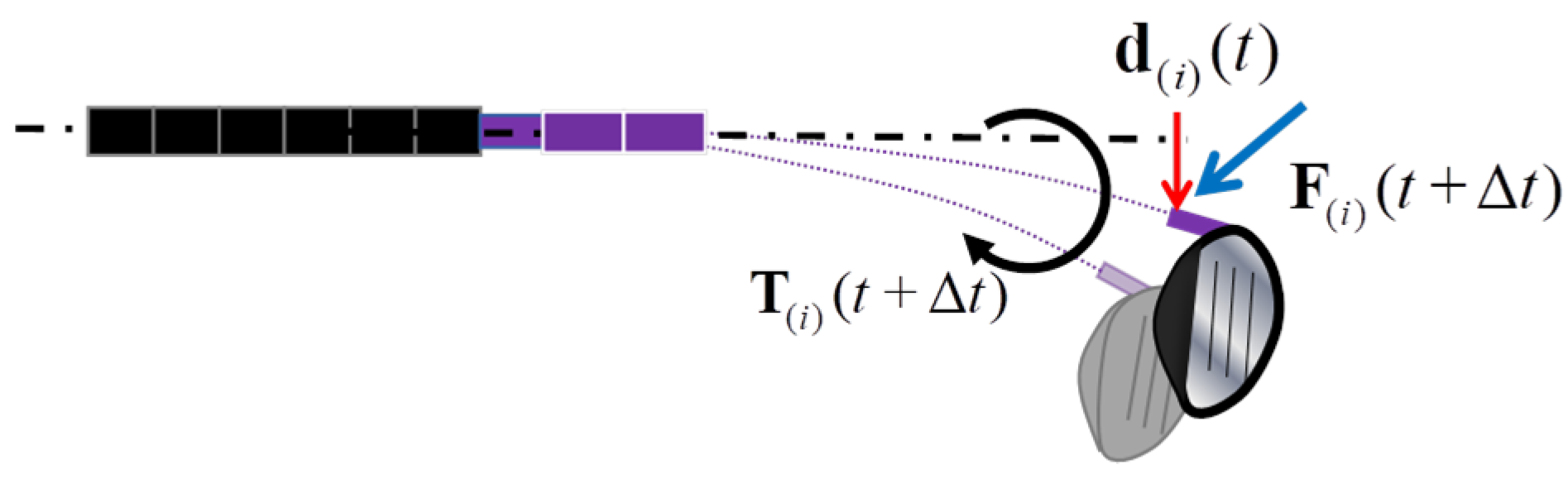
2.3. Deflection Torque for Each Club Node

In our previous study [7], we investigated the influence of the torque generated by shaft deflection (hereafter: def-torque). t indicates the arbitrary time and Δt is the sampling period. First, we define the displacement of the i-th node at t as d(i) (t). We then define the generalized force acting on the i-th node at t + Δt as F(i) (t + Δt) . The def-torque T(i) (t + Δt) at t + Δt is generated by vector cross product d(i) (t) and F(i) (t + Δt) as below:
T ( i ) ( t + Δ t ) = d ( i ) ( t ) × F ( i ) ( t + Δ t )
This torque is considered to act to the i-th node (Figure 3). Finally, calculating Equation (3) in all nodes, def-torque was added to Equation (2).

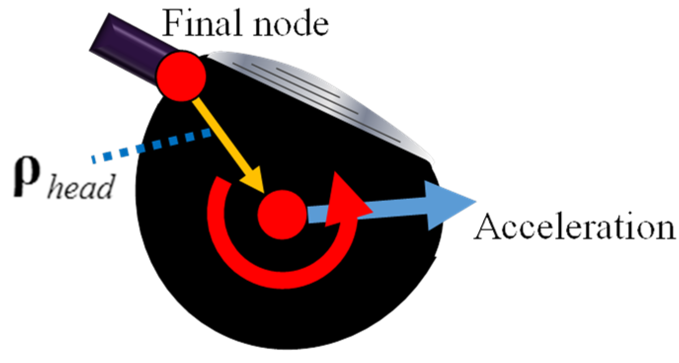
2.4. Head-Torque Caused by Grip Acceleration

In this study, we considered the influence of grip acceleration on the club head. The torque, taking account of the combination of the grip acceleration and the position of the club head centroid, was added to Equation (2). This torque (hereafter: Head-torque) is obtained by:
T h e a d = m h e a d ρ h e a d × ( [ S ] T ( r ^ ¨ g ^ ) )
ρ h e a d   is the vector for the direction from the final node of the shaft to the club head centroid (Figure 4). mhead is the club head’s mass, and [ S ] T ( r ^ ¨ g ^ ) is the acceleration vector of the grip end on the rotation coordinate system.

3. Analysis Method

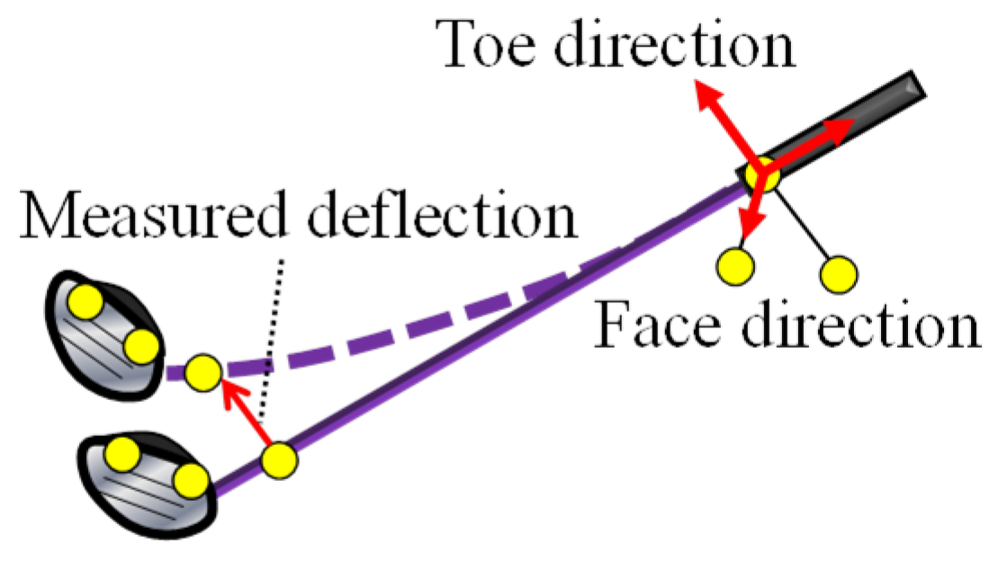
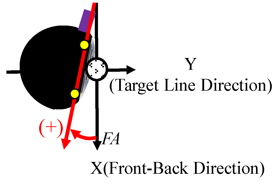
3.1. Experimental Measurements

Shaft movement during the swing was measured with a motion capture system (Vicon Blade). The sampling frequency was 500 [Hz] and markers were attached to the grip, tip of the shaft, and head (Figure 5). The examinee was an average golfer, and measurements were taken 10 times. Measured data of all markers were filtered using a 20 Hz low-pass filter. The rotation coordinate system on the grip was composed of three directions (the toe direction, face direction, and shaft axis direction) generated by using the markers attached to the grip (Figure 5). Using this coordinate system and the position of the marker attached to the tip of shaft, we computed the measured deflection of the shaft’s tip in the toe and face directions.
In this study, club head kinematics at ball impact were computed in order to investigate the influence of the Head-torque. Club head speed, path angle, attack angle, and face angle were computed by using the position of the markers attached to the club head [11]. The club head speed (hereafter: HS) was defined as the average velocity of the markers ranging from just before ball impact to ball impact. The club head orientation angles were computed relative to the inertial coordinate system. First, the trajectory of the middle point of the markers was projected on a plane composed of the X (front-back direction) and Y (target line direction) axes in the inertial coordinate system. The path angle (hereafter: Path) was defined as the angle between this trajectory and the Y axis in the inertial coordinate system (Figure 6). Moreover, the trajectory of the middle point of the markers was projected on a plane composed of the Y and Z (vertical direction) axes in the inertial coordinate system. The attack angle (hereafter: AA) was defined as the angle between this trajectory and the Y axis in the inertial coordinate system (Figure 7). Furthermore, the vector linking the markers was projected on a plane composed of the X and Y axes in the inertial coordinate system at ball impact. The face angle (hereafter: FA) was defined as the angle between this vector and the X axis in the inertial coordinate system (Figure 8). Ball impact was defined as the previous moment when either marker attached to the club head pass through the origin point of the inertial coordinate system.

3.2. Simulation

Using the measured data and Equations (2)–(4), we computed each generalized force. By inputting each generalized force into Equation (1), we computed the deflection of the shaft during the swing from address to ball impact, and club head kinematics at ball impact with the Newmark β method (β = 1/4). The simulation model was programed by MATLAB.

4. Results and Discussions

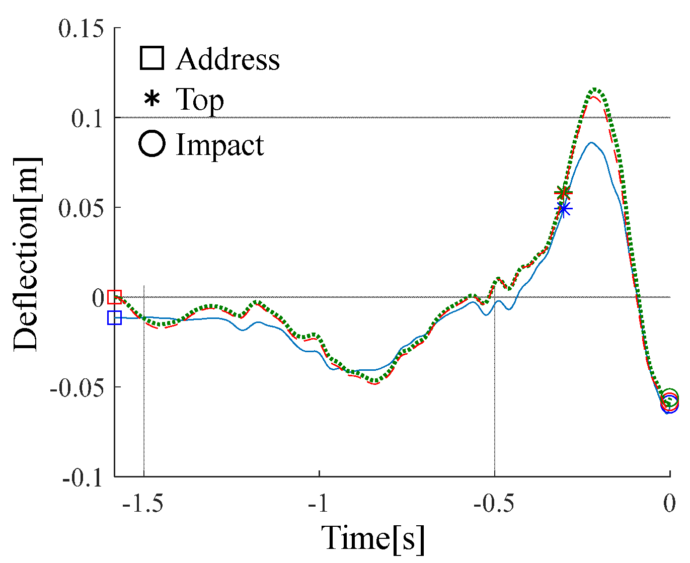
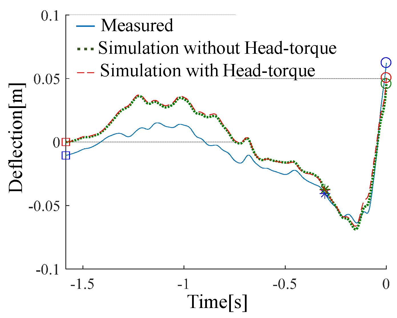
4.1. Comparison of Measured and Simulated Results of Club Shaft Deflection

We established the measured and simulated results of deflection in the toe and face directions in an arbitrary trial (Figure 9 and Figure 10). In these figures, the blue line is the measured result, the red line is the simulated result with Head-torque, the green line is the simulated result without Head-torque, the square (□) is the address timing (−1.584 [s]), the asterisk (*) is the top timing (−0.304 [s]), and the circle (○) is the impact timing defined as 0 [s]. In order to investigate the influence of the Head-torque, we compared these simulated results with the measured results. First, we computed the difference every 10 trials between the measured and simulated deflection values at the top and at ball impact. Moreover, the mean value of all differences were computed using the results with Head-torque and results without Head-torque, respectively (Table 1). As shown in Table 1, there was no significant difference between the simulated values with Head-torque and values without Head-torque. Therefore, club shaft deflection was not influenced by the Head-torque generated by grip acceleration.

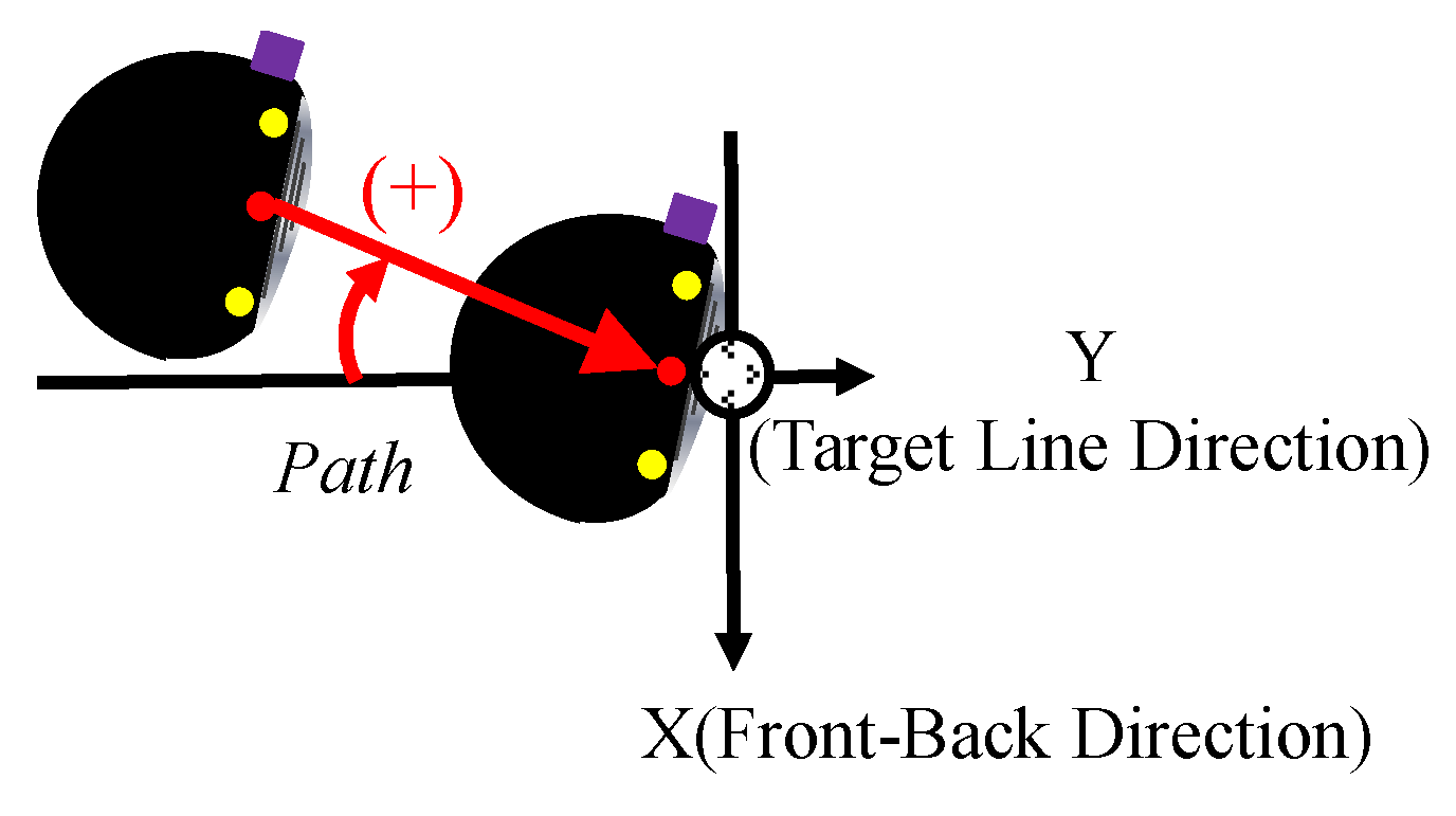
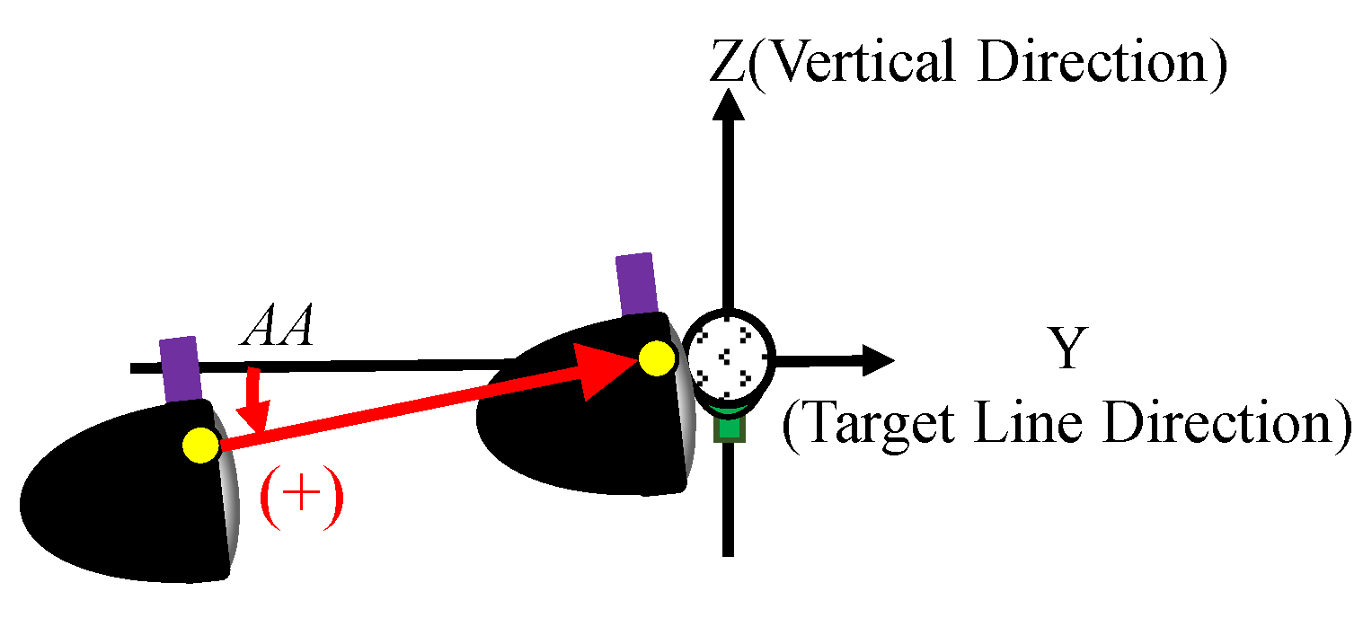
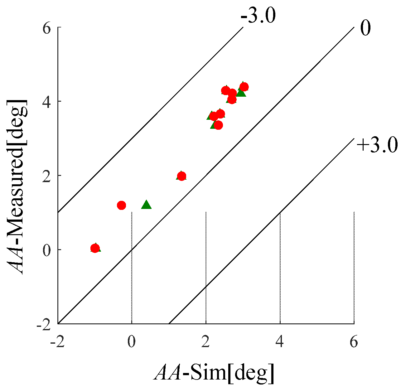
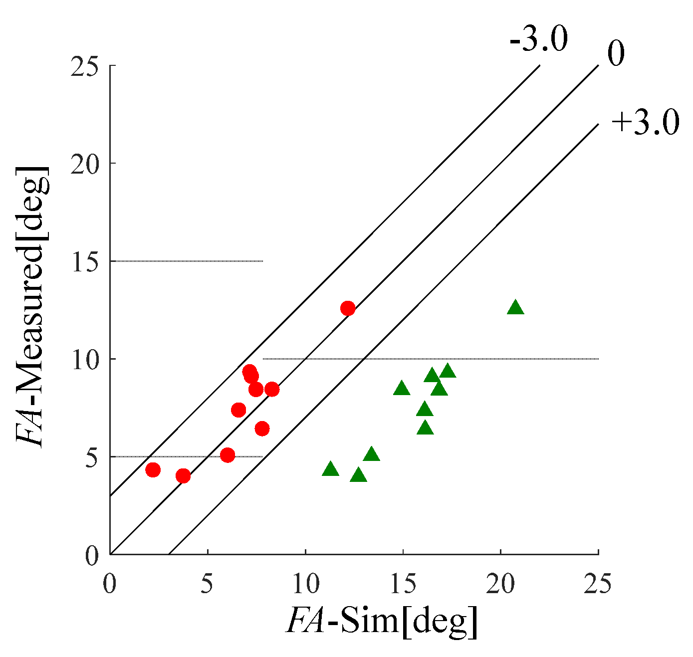
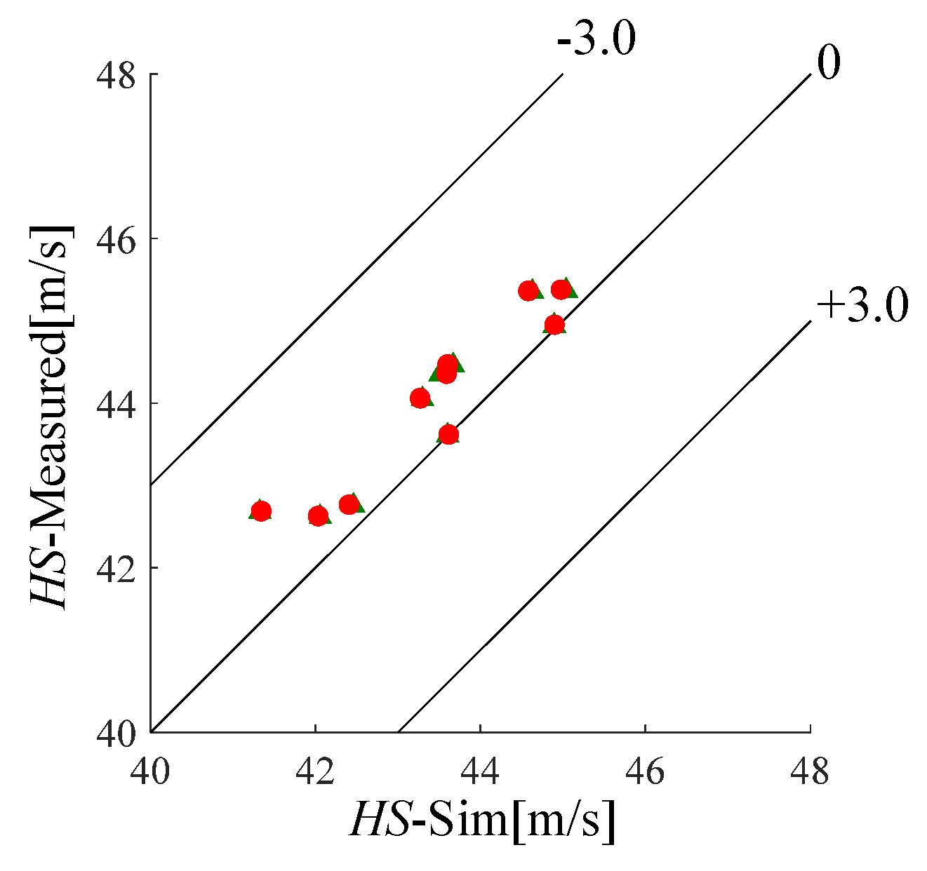
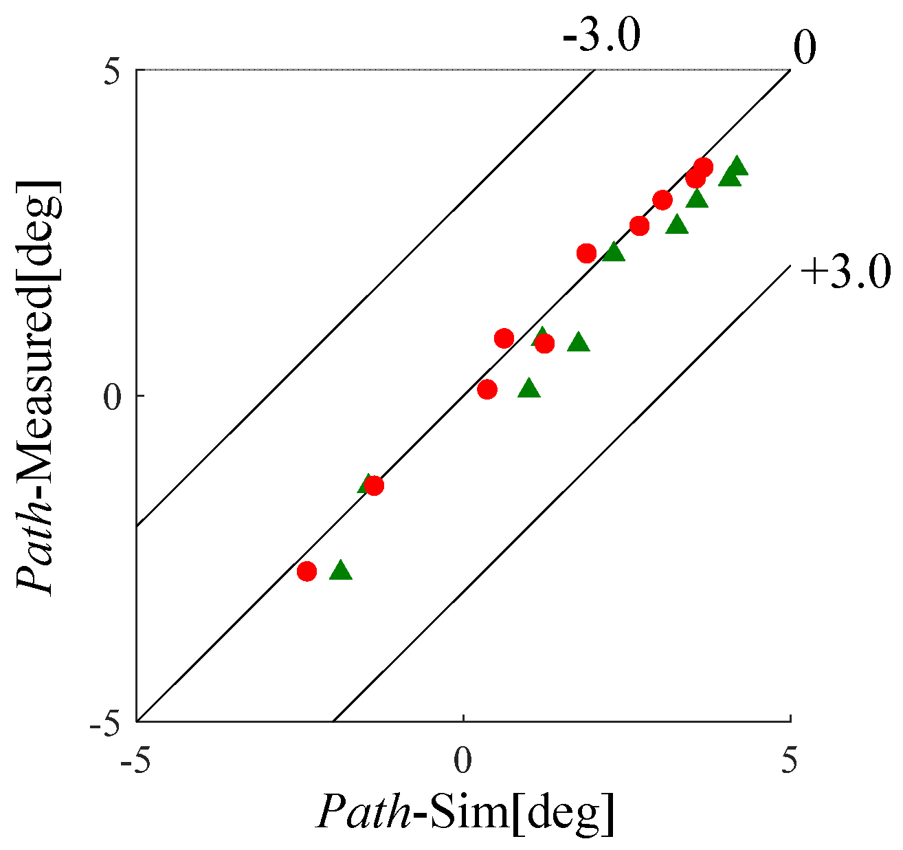
4.2. Comparison of Measured and Simulated Results of Club Head Kinematics

The club head kinematics at ball impact every 10 trials are shown in Figure 11, Figure 12, Figure 13 and Figure 14. In these figures, the horizontal axis is the simulated value, the vertical axis is the measured value, the circle marks (●) are the results with Head-torque, and the triangle marks (▲) is the results without Head-torque. Moreover, the mean value and standard deviation of the difference between the measured and simulated values were computed in order to analyse the influence of the Head-torque (Table 2). In comparing the values in Table 2, it was found that Path, and FA in this study, particularly, were close to the measured values, but HS and AA were not. In more detail, for Head-torque, the mean value of FA was lower than that of our previous study. As a result, it was concluded that the Head-torque generated by grip acceleration seems to allow the club head to rotate a bit more at ball impact.

5. Conclusions

In this paper, in order to investigate the influence of grip acceleration on the club head during a golf swing, Head-torque was added to our simulation model, and we computed the shaft deflection during the swing and the club head kinematics at ball impact. We reached the following conclusions:
(1)
The deflection of the tip of the shaft was not influenced by the Head-torque generated by grip acceleration.
(2)
The HS and AA simulations was not influenced by the Head-torque generated by grip acceleration.
(3)
Considering the influence of the Head-torque generated by grip acceleration, the Path and FA simulations was close to the measured values.

References

  1. MacKenzie, S.J.; Boucher, D.E. The influence of golf shaft stiffness on grip and clubhead kinematics. J. Sports Sci. 2017, 35, 105–111. [Google Scholar] [CrossRef] [PubMed]
  2. Worobets, J.; Stefanyshyn, D. The influence of golf club shaft stiffness on clubhead kinematics at ball impact. Sports Biomech. 2012, 11, 239–248. [Google Scholar] [CrossRef] [PubMed]
  3. Tsujiuchi, N.; Koizumi, T.; Tomii, Y. Analysis of the influence of golf club design on the golf swing. Eng. Sport 2002, 4, 537–544. [Google Scholar]
  4. MacKenzie, S.J.; Sprigings, E.J. Understanding the mechanisms of shaft deflection in the golf swing. Sports Eng. 2010, 12, 69–75. [Google Scholar] [CrossRef]
  5. Sandhu, S.; Millard, M.; McPhee, J.; Brekke, D. 3D dynamic modelling and simulation of a golf drive. Procedia Eng. 2010, 2, 3243–3248. [Google Scholar] [CrossRef]
  6. Matsumoto, K.; Tsujiuchi, N.; Koizumi, T.; Ito, A.; Ueda, M.; Okazaki, K. The Influence of a Golf Club’s Inertia on Shaft Movement during the Golfer’s Swing. In Proceedings of the 11th conference of the International Sports Engineering Association, Procedia Engineering, Delft, The Netherland, 11–14 July 2016; Volume 147, pp. 360–365. [Google Scholar]
  7. Matsumoto, K.; Tsujiuchi, N.; Ito, A.; Ueda, M.; Okazaki, K.; Taiki, S. Effect of Inertia for Shaft Movement generated by a Golf Swing. In Proceedings of the 8th Asian Conference on Multibody Dynamics, Kanazawa, Japan, 7–10 August 2016. [Google Scholar]
  8. Iwatsubo, T.; Matsuhisa, H.; Inoue, Y.; Utsuno, H.; Kawamura, S.; Kanki, H.; Koizumi, T.; Shiohata, K.; Tsujiuchi, N.; Nakagawa, N. Basics of Vibration Engineering; Morikita Publishing Co., Ltd.: Tokyo, Japan, 2014; pp. 130–134. [Google Scholar]
  9. Komatsu, K. Machine Architecture Vibration Science FEM and Analysis of Response by MATLAB; Morikita Publishing Co., Ltd.: Tokyo, Japan, 2009; pp. 38–39. [Google Scholar]
  10. Nagamatsu, A. Modal Analysis; Baifukan CO., Ltd.: Tokyo, Japan, 1985; pp. 176–216. [Google Scholar]
  11. Matsumoto, K.; Tsujiuchi, N.; Ito, A.; Taiki, S.; Ueda, M.; Okazaki, K. Estimation of Club Head Posture during Golf Swing using three-dimensional FEM model. In Proceedings of the Symposium on Sports and Human Dynamics 2016, Yamagata, Japan, 9–11 December 2016. (In Japanese). [Google Scholar]
Figure 1. Physical model with multistage beam. The model is divided into three parts: the golfer’s grip part considered as a spring model, shaft, and head.
Proceedings 02 00241 g001
Figure 2. Vectors demonstrating each position on the golf club model. r is the vector for the direction from the ball position to the grip end and ρ is the vector for the direction from the grip end to the origin of an arbitrary node on the shaft coordinate. d is the displacement of the node.
Proceedings 02 00241 g002
Figure 3. Deflection torque at the i-th element. We define the displacement of the i-th node at t as d(i) (t). We then define the generalized force acting on the i-th node at t + Δt as F(i) (t + Δt). The deflection torque T(i) (t + Δt) at t + Δt is generated by vector cross product d(i) (t) and F(i) (t + Δt).
Proceedings 02 00241 g003
Figure 4. Head-torque is the combination of the grip acceleration and the position of the club head centroid. ρ h e a d     is the vector for the direction from the final node of the shaft to the club head centroid.
Proceedings 02 00241 g004
Figure 5. Markers were attached to the grip, tip of the shaft, and head. The rotation coordinate system on the grip was composed of three directions (the toe direction, face direction, and shaft axis direction). Using this coordinate system and the position of the marker attached to the tip of the shaft, we computed the measured deflection of the tip of the shaft in the toe and face direction.
Proceedings 02 00241 g005
Figure 6. Definition of Path.
Proceedings 02 00241 g006
Figure 7. Definition of AA.
Proceedings 02 00241 g007
Figure 8. Definition of FA.
Proceedings 02 00241 g008
Figure 9. Comparison of measured and simulated results of deflection in the toe direction.
Proceedings 02 00241 g009
Figure 10. Comparison of measured and simulated results of deflection in the face direction.
Proceedings 02 00241 g010
Figure 11. Comparison of measured and simulated results of HS. The triangle marks (▲) show the result without Head-torque, and the circle marks (●) show Head-torque.
Proceedings 02 00241 g011
Figure 12. Comparison of measured and simulated results of Path. The triangle marks (▲) show the result without Head-torque, and the circle marks (●) show Head-torque.
Proceedings 02 00241 g012
Figure 13. Comparison of measured and simulated results of AA. The triangle marks (▲) show the result without Head-torque, and the circle marks (●) show Head-torque.
Proceedings 02 00241 g013
Figure 14. Comparison of measured and simulated results of FA. The triangle marks (▲) show the result without Head-torque, and the circle marks (●) show Head-torque.
Proceedings 02 00241 g014
Table 1. Difference between measured and simulated results of club shaft deflection.
Toe-Top (mm)Face-Top (mm)Toe-Impact (mm)Face-Impact (mm)
Sim(no-Head-torque)11.3 ± 2.79.9 ± 6.04.0 ± 2.312.9 ± 6.5
Sim(Head-torque)10.0 ± 2.79.8 ± 6.03.5 ± 2.89.0 ± 6.1
Table 2. Difference between measured and simulated results of club head kinematics.
HS (m/s)Path (deg)AA (deg)FA (deg)
Sim(no-Head-torque)0.5 ± 0.40.6 ± 0.31.2 ± 0.38.1 ± 1.0
Sim(Head-torque)0.5 ± 0.40.1 ± 0.21.2 ± 0.30.6 ± 1.1
Publisher’s Note: MDPI stays neutral with regard to jurisdictional claims in published maps and institutional affiliations.

