Proceeding Paper

Interpolating Binary and Multivalued Logical Quantum Gates †

1
Telecom Department, CentraleSupélec, Lab. des Signaux et Systèmes-L2S (UMR8506)-CNRS, 91190 Gif-sur-Yvette, France
2
LMSSC, CNAM, Paris, Department of Mathematics, University Paris-Sud, 91400 Orsay, France
*
Author to whom correspondence should be addressed.
Presented at the 4th International Electronic Conference on Entropy and Its Applications, 21 November–1 December 2017; Available online: http://sciforum.net/conference/ecea-4.
Proceedings 2018, 2(4), 152; https://doi.org/10.3390/ecea-4-05006
Published: 20 November 2017

Abstract

:
A method for synthesizing quantum gates is presented based on interpolation methods applied to operators in Hilbert space. Starting from the diagonal forms of specific generating seed operators with non-degenerate eigenvalue spectrum one obtains for arity-one a complete family of logical operators corresponding to all the one-argument logical connectives. Scaling-up to n-arity gates is obtained by using the Kronecker product and unitary transformations. The quantum version of the Fourier transform of Boolean functions is presented and a Reed-Muller decomposition for quantum logical gates is derived. The common control gates can be easily obtained by considering the logical correspondence between the control logic operator and the binary logic operator. A new polynomial and exponential formulation of the Toffoli gate is presented. The method has parallels to quantum gate-T optimization methods using powers of multilinear operator polynomials. The method is then applied naturally to alphabets greater than two for multi-valued logical gates used for quantum Fourier transform, min-max decision circuits and multivalued adders.

Published: 20 November 2017

1. Introduction

Quantum calculation methods are becoming a strategic issue for emerging technologies such as quantum computing and quantum simulation. Because of the limited (at this date) quantum computational resources available it is very important to reduce the resources required to implement a given quantum circuit. The problem of optimal quantum circuit synthesis is an important topic much of the effort focuses on decomposition methods of logical gates. Quantum reversible gates have been extensively studied using principally Boolean functions implemented on Clifford, controlled-not and Toffoli gates and also non-Clifford such as the T gate. The advantages and drawbacks for privileging certain families of gates has been thoroughly investigated. Basically all methods rely on the control-logic paradigm as was first proposed by David Deutsch in [1]. The 2-qubit controlled-not gate being its simplest element resulting in the operation | x , y | x , x y where the exclusive disjunction ( X O R , ) acts as logical negation on qubit y when the control qubit x is at one and leaves it unchanged otherwise. The universality of this logic is assured by the double-controlled-not or Toffoli gate with the operation on three qubits | x , y , z | x , y , x y z . This gate operates on the third qubit z , when the conjunction is met on the control bits x and y (both must be 1) being thus equivalent to a negated binary conjunction N A N D gate, which is known to be universal. These logical controlled-gates transform the qubits as reversible permutation operators i.e., they are not diagonal in the computational basis.
In recent years many synthesizing methods for quantum circuits actually use operators that are diagonal in the computational basis because of the simpler resulting mathematical operations. The controlled- Z and the double-controlled- Z gates are used to build controlled-not C and Toffoli gates T O . Solutions using diagonal T and S gates, as will be shown hereafter, are also popular, also the stabilizer formalism and surface codes use families of Clifford diagonal gates. So in some way the “back to diagonal” trend seems to present benefits, this is also justified when one considers questions in quantum physics where much effort is employed to define Hamiltonians and the corresponding energy spectrum (eigenvalues) and stationary states (eigenstates), which can then be implemented in quantum simulation models.
A question arises: can logical calculations be formalized someway directly in the qubit eigenspace? The answer seems to be affirmative and in a rather simple way too. A proposal has been given by making parallels between propositional logic and operator linear algebra in the framework of “Eigenlogic” [2,3], the idea is that Boolean algebra operations can be represented by operators in Hilbert space, using projection operators as developed in [2] and extended to angular momentum operators as shown in [3] and generalized in this paper.
A theoretical justification could be inspired by Pierre Cartier in [4], relating the link between the algebra of logical propositions and the set of all valuations on it, he writes: “...in the theory of models in logic a model of a set of propositions has the effect of validating certain propositions. With each logical proposition one can associate by duality the set of all its true valuations represented by the number 1 . This correspondence makes it possible to interpret the algebra of propositions as a class of subsets, conjunction and disjunction becoming respectively the intersection and union of sets. This corresponds to the Stone duality proved by the Stone representation theorem and is one of the spectacular successes of twentieth century mathematics.... The development of quantum theory led to the concept of a quantum state, which can be understood as a new embodiment of the concept of a valuation”. The idea is not new, and stems from John Von Neumann’s proposal of “projections as propositions” in [5] which was subsequently formalized in quantum logic with Garret Birkhoff in [6]. These topics have been thoroughly discussed in [2].
But because nowadays quantum logic is mostly interested in aspects concerning operations going beyond and also in contrast with the principles of classical logic it is still not considered as an operational tool for quantum computing even though many bridges have been made [7,8]. The aim of Eigenlogic is on the other side to fully exploit the logical structure offered by the operational system in the eigenspace with of course the possibility to look outside at other basis representations this leads for example to fuzzy logic applications [3] as will be explicated hereafter.
While most of the research is currently devoted to quantum circuit and algorithm developments based on the use of quantum operators working in binary (Boolean) systems through the manipulation of qubits, there are many possibilities for the exploitation of observables with more than two non-degenerate eigenvalues and the theory of multi-valued-logic is very naturally applicable to the design and analysis of these systems for further details on references.

2. Eigenlogic Interpretation

2.1. Historical Background

George Boole gave a mathematical symbolism through the two numbers {0,1} representing resp. the “false” or “true” character of a proposition [9] (see [2] for an historical discussion). An idempotent symbol x verifies the equation: x 2 = x which admits only two possible solutions: 0 and 1, this equation was considered by Boole the “fundamental law of thought”. As will be emphasized here the algebra of idempotent symbols can also be interpreted as a set of commuting projection operators in linear algebra.
John von Neumann in [5] was the first to associate projection operators with logical propositions, which subsequently was formalized in an independent discipline: quantum logic [6]. He also introduced the formalism of the density matrix in quantum mechanics where a pure quantum state | ψ can also be represented by a projection operator: ρ = | ψ ψ | , which is a ray (a rank-1 idempotent projection operator spanning a one-dimensional subspace). All these concepts lay at the foundations of quantum theory.

2.2. Binary Eigenlogic

A linear algebraic method is presented here, for binary, multi-valued and fuzzy logic using observables in Hilbert space. All logical connectives have their corresponding observable where the truth values correspond to eigenvalues. In this way propositional logic can be formalized by using tensor combinations of elementary quantum observables. The outcome of a “measurement” of a logical observable will give the truth value of the associated logical proposition, and becomes thus interpretable when applied to vectors of its eigenspace, leading to an original insight into the quantum measurement postulate.
A projection operator in Hilbert space is associated to a logical proposition, the operator being Hermitian it has the properties of a quantum observable and is considered here a logical observable. This view is named Eigenlogic [2,3] and can be summarized as follows:
  • eigenvectors in Hilbert space ⟺ interpretations (atomic propositional cases)
  • logical observables ⟺ logical connectives
  • eigenvalues ⟺ truth values
The general form of a logical observable can be expressed as a development:
F = f ( 0 ) Π 0 + f ( 1 ) Π 1 = d i a g [ f ( 0 ) , f ( 1 ) ]
the terms in the development are the 2-dimensional rank-1 projectors Π 0 and Π 1 , the cofactors f ( 0 ) and f ( 1 ) are the eigenvalues corresponding to the truth values taking the values { 0 , 1 } . This allows to generate the 4 one-argument logical observables:
F A = 0 Π 0 + 1 Π 1 = Π , F A ¯ = 1 Π 0 + 0 Π 1
F = 0 Π 0 + 0 Π 1 = O 2 , F T = 1 Π 0 + 1 Π 1 = I d
these are represented by the logical projector A , its negation A ¯ , contradiction and tautology T . Negation corresponds to complementation obtained by subtracting from the identity operator I d :
F ¯ = I d F
For the one-argument case, n = 1 , the eigenvectors | 0 and | 1 correspond to the 2-dimensional orthonormal vectors:
| 0 = ( 1 0 ) , | 1 = ( 0 1 )
Vectors | 0 and | 1 , form the canonical basis, and correspond in quantum mechanics to qubits corresponding respectively to the north and south polar points on the Bloch sphere (see Figure 1).
The two-argument logical observables can be developed in a similar way:
F 2 = d i a g [ f ( 0 , 0 ) , f ( 0 , 1 ) , f ( 1 , 0 ) , f ( 1 , 1 ) ]
There are 2 2 n logical connectives for a n -argument (arity) system. For n = 1 this gives the four connectives described above. For n = 2 one has 16 binary logical connectives: conjunction ( ,   A N D ) ; disjunction ( ,   O R ) ; exclusive disjunction ( , X O R ) ; logical projectors (A, B); material implication ; Sheffer stroke ( ,   N A N D ) ; tautology (T). The remaining ones can be derived by the classical theorems of logic. All logical connectives are uniquely characterized by their truth table i.e., by their logical semantics. The complete family of the 16 two-argument connectives are shown on Table 1.
For two arguments eigenvectors are named | a   b where the arguments a and b take the values { 0 , 1 } and represent one of the four possible cases (logical interpretations) for the input of the logical connective, they are calculated using the Kronecker product of the qubit state vectors | 0 and | 1 , explicitly:
| 00 = | 0 | 0 = ( 1 , 0 , 0 , 0 ) t , | 01 = | 0 | 1 = ( 0 , 1 , 0 , 0 ) t
| 10 = | 1 | 0 = ( 0 , 0 , 1 , 0 ) t , | 11 = | 0 | 0 = ( 0 , 0 , 0 , 1 ) t
Using the following linear bijection between the projection observable F and a reversible observable G :
G = I d 2 F
one obtains a logical binary system using now the numbers { + 1 , 1 } . Observables F and G commute, so they have the same system of eigenvectors. The eigenvalues that correspond to the truth values, respectively “false” and “true”, are respectively + 1 and 1 .
In this case the generating observable, the seed operator, is the Pauli matrix σ z also named the Z gate:
σ z = Z = I d 2 Π 1 = ( + 1 0 0 1 )
For two arguments, in the system { + 1 , 1 } , the logical dictators U and V (the equivalent of the logical projectors A and B for the system { 0 , 1 } ) are function of Z by:
U = Z I d = d i a g ( + 1 , + 1 , 1 , 1 ) , V = I d Z = d i a g ( + 1 , 1 , + 1 , 1 )
Negation in the system { + 1 , 1 } is obtained by multiplying by 1 :
G ¯ = G
This formulation leads to the same results as for the Fourier transform model of Boolean functions developed in [10] and extended to the quantum case in [11].

2.3. Fuzzy Eigenlogic

What happens when the quantum state is not one of the eigenvectors of the logical system? In quantum mechanics one can always express a quantum state-vector | ψ as a combination on a complete orthonormal basis, in particular on the canonical eigenbasis of the logical observable family, this gives:
| ψ = c 00 | 00 + c 01 | 01 + c 10 | 10 + c 11 | 11
When only one of the coefficients is not zero, then one obtains a fixed interpretation for the proposition corresponding to one of the eigenstates and goes back to the preceding discussion.
Fuzzy logic deals with truth values that can take values between 0 and 1 , so the truth of a proposition can lie between “completely true” and “completely false”. When more than one coefficient in the development of | ψ is non-zero one can consider a fuzzy interpretation.
For a projective observable F measured in the context of the quantum state | ψ the mean value (Born rule) gives directly a probability measure by:
p | ψ = ψ | F | ψ = T r ( ρ · F )   with   ρ = | ψ ψ |   the   density matrix
The obtained mean value of the logical observable F is thus a fuzzy measure of the truth of a logical proposition in the form of a fuzzy membership function μ .
For one-argument an arbitrary 2-dimensional quantum state can be written as:
| ϕ = sin α | 0 + e i β cos α   | 1
where the angles α and β are real numbers.
The membership function is the quantum mean value of the logical projector observable A = Π , given by:
μ ( a ) = ϕ | Π | ϕ = cos 2 α
Using the angular transformation α = θ / 2 and β = φ / 2 one can represent the angles θ and φ on the Bloch sphere (see Figure 1).
A quantum compound state can be built by taking the tensor product of two elementary states: | ψ   |   φ p >   |   φ q , where |   φ p   c o s   θ p 2   | 0 + e i ϕ p   s i n   θ p 2   | 1 (for |   φ q we have a similar expression). Now putting s i n   θ p 2 = p and s i n   θ q 2 = q represent the probabilities of being in the “True” state | 1 for spins 1 / 2 oriented along two different axes θ p and θ q .
One can calculate the fuzzy membership function of the corresponding “logical projector” for the two-argument case:
μ ( a ) = ψ | Π     I | ψ = p ( 1 q ) + p q = p   ,   μ ( b ) =   ψ | I   Π | ψ = q
this shows that the mean values correspond to the respective probabilities. Now let’s “measure” for example the conjunction and the disjunction, using the observables in Table 1, this gives:
μ ( a b ) = ψ   | Π Π | ψ = p q = μ ( a ) μ   ( b )
μ ( a b ) = p + q p q = μ ( a ) + μ ( b ) μ ( a ) μ ( b )
So in this approach fuzzy logic arises naturally when considering vectors outside the eigensystem. The fuzzy membership function is obtained by the quantum mean value (Born rule) of the logical projection observable and turns out to be a probability measure. Fuzziness arises because of the quantum superposition of interpretations, the truth of a proposition being in this case a probabilistic value ranging from completely false to completely true.

2.4. Multivalued Eigenlogic

The recently observed revival of interest in applying multi-valued logic (MVL) to the description of quantum phenomena is closely related to fuzzy logic. MVL is of interest to engineers involved in various aspects of information technology and has a long history, for example it is at the basis of the programming language HDL (Hardware Description Language).
In MVL the total number of logical connectives for a system of m values and n arguments is the combinatorial number m m n , giving for example for a 3-valued 2-argument system 3 3 2 = 19 , 683 different logical connectives. This shows that using the totality of the different logical connectives in a single mathematical framework becomes intractable, but some special connectives play an important role.
MVL is naturally associated to the physical quantity: quantum angular momentum. The obseravble of the z component of the angular momentum observable for = 1 is:
L z =   d i a g ( + 1 , 0 , 1 )
one can associate the eigenvalues to the logical truth values:
false   F + 1 , neutral   N 0 , true   T 1
In this case, as will be shown using the method presented hereafter, the logical observables can be expressed as a unique development by spectral decompositions over rank-1 projection operators:

3. The Interpolation Method for Quantum Operators

3.1. Lagrange and Cayley-Hamilton Interpolation

The method presented here is inspired from classical Lagrange interpolation where the “variable” is represented by a seed operator acting in Hilbert space, possessing m distinct eigenvalues, i.e., it is non-degenerate. The values are not fixed meaning that one can work with different alphabets, in the binary case one uses classically the Booleans { 0 , 1 } , but also { + 1 , 1 } can be considered. What this method will show is that for whatever finite system of values, unique logical operators can be defined. In the multivalued case, popular choices are, for example { 0 , 1 , 2 , , m 1 } formalized in Post logic [12] and rational fractional values in the unit interval [ 0 , 1 ] giving the system { 0 , 1 m , 2 m , , m 1 m , 1 } of m + 1 values as used in Łukasiewicz logic. Other convenient numerical choices are i.e. the balanced ternary values { + 1 , 0 , 1 } for qutrits.
When the eigenvalues are real the corresponding logical operators are observables, e.g., Hermitian operators. Many logical gates are of this type, the most popular ones are the one-qubit Pauli- Z , Pauli- X , Hadamard H , phase S and T gates, the two-qubit controlled-not, controlled- Z gate and the swap gate and the universal three-qubit Toffoli gate T O .
The possibility of using complex values can also be considered and this has applications for specific problems such as in T -gate synthesis and quantum Fourier transform in this last case one considers the roots of unity giving the m -eigenvalue spectrum: { e i 2 π 0 , e i 2 π 1 m ,   e i 2 π 2 m , , e i 2 π m 1 m } .
In each situation one starts by defining the seed operator Λ with m non-degenerate eigenvalues λi. The density matrix of an eigenstate | λ i is Π λ i = | λ i   >   <   λ i | , and corresponds to a rank- 1 projection operator, a ray, for this state. It is obtained by the following expression:
Π λ i ( Λ ) = j = 1 , j i m Λ λ j I m λ i λ j
The development is unique according to the Cayley-Hamilton theorem, this expression can be put in polynomial form consisting in a linear combination of powers up to m 1 of the seed operator Λ , it is a rank- 1 projection operator over the m dimensional Hilbert space and can be expressed as a m   ×   m square matrix. All the rank- 1 projection operators obtained in the eigensystem commute and span the entire space by the closure relation:
i = 1 m Π λ i = i = 1 m | λ i >   < λ i | = I m
as outlined in [2,3] in Eigenlogic eigenvalues correspond to logical truth values (values { 0 , 1 } for a Boolean system) and one can make the correspondence between propositional logical connectives and operators in Hilbert space. The truth table of a logical connective corresponds to different semantic interpretations, each interpretation is a fixed attribution of truth values to the elementary propositions (the “inputs”) composing the connective. In Eigenlogic each interpretation corresponds to one of the eigenvectors and the associated eigenvalue to the corresponding truth-value for the considered logical connective.
It is well known that logical connectives can be expressed through arithmetic expressions, these are closely related to polynomial expressions over rings, but with expressions using ordinary arithmetic addition and subtraction instead of their modular counterpart as used in Boolean algebra. These topics were thoroughly discussed in [2] for the Boolean values { 0 , 1 } . Arithmetic developments of logical connectives are often used, for example, in the description of switching functions for decision logic design. A good review is given in [13].
In logic, functions and arguments take the same values. For Boolean functions the possible values are the two numbers 0 and 1 corresponding respectively to the false and true character of a logical proposition. So considering an arithmetic expression for an arity-one logical connective ( a ) and choosing the m distinct logical values a i , the value taken by the logical function at one of these points a p , is ( a p )     { a 1 ,   a 2 ,   ,   a m } , also one of these values. The corresponding unique logical operator is given by the interpolation development:
F = i = 1 m ( a i )   Π a i
this operator decomposition is proved by Sylvester’s theorem and represents the spectral decomposition of the operator. The projection operators are obtained by the interpolation formula with λ i   =   a i .
One must then consider the operators corresponding to the elementary propositions of the logical connectives. This is a straightforward procedure in Eigenlogic. For arity-one logical connectives, these are function of one single elementary proposition which corresponds, in the method proposed here, to the seed operator Λ . These concepts will become clearer with some examples.

3.2. Scaling to higher arity for more logical arguments

The scaling is obtained by following the same procedure as for classical interpolation methods for multivariate systems using tensor products (see e.g., [14]). Here the chosen convention for the indexes is the one given by David Mermin in [15] where index 0 indicates the lowest digit, index 1 the next and so on... For arity- 2 one considers two operators P 1 and Q 0 corresponding to two elementary propositional variables. One can write by the means of the Kronecker product :
P 1 = Λ I   ,   Q 0 = I Λ
for arity- 3 using three operators one has:
P 2 = Λ I I   ,   Q 1 = I Λ I   ,   R 0 = I I Λ
for higher arity- n the procedure can be automatically iterated.
The logical operators can then be calculated, these are multi-linear combinations of the elementary operators P i , Q j . For example the simplest operators are products. Due to logical completeness (demonstrated by Emil Post in [12]) there will be for an m -valued n -arity system exactly m m n logical operators forming a complete family of commuting logical operators. Logical completeness has also another important consequence: there are always universal connectives from which all the others can be derived, it has been shown, also in [12], that for an m-valued arity-2 system one needs at least two universal connectives, in the case of Post logic these turn out to be the general negation (cyclic permutation of all values a i     a i + 1 ) and the M a x connective (takes the highest of the two input values) these reduce to Boolean connectives for binary values where the M a x connective becomes the disjunction ( O R , ). The logical operators obtained here for an m -valued n -arity system are represented by m n × m n square matrices.

4. Building the Controlled-Not and Toffoli Binary Gates

4.1. One Qubit Gates

In the computational basis the Z and X and Hadamard H gate’s matrix forms are:
Z = ( + 1 0 0 1 ) , X = ( 0 1 1 0 ) , H = 1 2 ( + 1 1 1 1 )
One has to consider the useful opeerator transformation X   =   H Z H and also Z   = H X H (because H 2 =   I ):
The seed operator for the system { + 1 , 1 } in the computational basis is:
Λ {   +   1 ,     1 }   =   Z   =   d i a g z (   +   1 ,   1 )
The one-qubit state vectors and projection operators are:
| 0   = ( 1 0 ) , | 1   =   ( 1 0 )
Π + 1 ( Z )   = 1 2   ( I   +   Z )   =   | 0   0 | , Π 1 ( Z )   = 1 2   ( I Z )   = | 1   1 |   =   Π
The same method can also be used when operators are not diagonal in the computational basis, for example one could have chosen the X gate as the seed operator by changing Z into X .
The seed operator and the two projection operators permit to write the four arity-one logical operators: Z (Dictator),     Z (Negation),   +   I (Contradiction) and     I (Tautology) (see [2,3] for a detailed discussion), the eigenvalues { + 1 , 1 } correspond respectively to False and True.
Before continuing for higher arity it is interesting to analyze the logical operator system corresponding to the Boolean values { 0 , 1 } , it is straightforward to see that in this case the seed operator, Λ { 0 ,   1 } , is the projection operator Π 1 =   Π given above, the other projection operator Π0 being the complement:
Λ { 0 ,   1 }   =   d i a g z ( 0 ,   1 ) =   Π 1 =   Π   = | 1   1 | , Π 0   =   I     Π   =   | 0       0 |
There are interesting tranformations for the operators when going from the system { + 1 , 1 } to the system { 0 , 1 } . Due to the properties of the operator Π (idempotent projection operator Π 2   =   Π ) and Z (self-inverse operator Z 2   =   I ) one can use the Householder transform:
Z   =   I     2   Π   =   (     1 ) Π   = e i π Π   = e i π 2   e i π 2   Z   ,   Z   | x     =   (     1 ) x | x    
This transform applies also for composite expressions and permits to transform operators with eigenvalues { 0 , 1 } into operators with eigenvalues { + 1 , 1 } and will be used hereafter to build the controlled-not C and Toffoli gates T O .
For arity-2, one considers the two elementary operators acting on qubit- 0 and qubit- 1 :
Z 0   =   I Z   ,   Z 1   =   Z I

4.2. Building Cz and CNOT gates

The controlled-z gate, named here C Z , is diagonal in the computational basis. The interpolation method described above and used in [3] gives directly the known [15] polynomial expression:
C Z =   d i a g z (   +   1 ,   +   1 ,   +   1 ,     1 )   =   1 2 (   I   +   Z 1   +   Z 0     Z 1   Z 0 )
One can consider some interesting interpretations using Eigenlogic [3]: the truth table is given by the structure of the eigenvalues of the C Z operator and corresponds to the logical connective conjunction (AND, ∧), where the values for {False, True} correspond here to the alphabet { +   1 ,   1 } . Also the logical operator for conjunction F A N D in the Boolean alphabet, { x ,   y }     { 0 ,   1 } , as demonstrated in [2], has a very simple form:
F A N D   =   Π Π   =   d i a g z ( 0 ,   0 ,   0 ,   1 ) , F A N D | x y =   x y   | x y  
applying this operator to the state | x y   one obtains the eigenvalue x y   =   1 , True, only for the state | 11   . One can transform this operator using the Householder transform in:
G A N D = I     2 F A N D = (     1 ) Π Π =   d i a g z ( 1 ,   1 ,   1 ,     1 )   = C Z
G A N D | x y =   C Z   | x y =   (     1 ) x y   | x y
justifying the interpretation of the C Z gate as a conjunction in Eigenlogic for the alphabet { +   1 ,   1 } .
The controlled-not operator, named here C , can be expressed straightforwardly, see e.g., [15], in its polynomial form on Z 1 and X 0 :
C   =   1 2 ( I   +   Z 1   +   X 0     Z 1   X 0 )
this expression can be derived from C Z using the transformation X 0 = H 0 Z 0 H 0 , b where the operator H 0 =   I H with H is the Hadamard gate defined above.
In the preceding section it has been emphasized that one can consider different basis to define the system and the respective seed operator.
Some important properties about projection operators (not necessarily commuting) have to outlined:
(i)
The Kronecker product of two projection operators is also a projection operator.
(ii)
If projection operators are rank-1 (a single eigenvalue is 1 all the others are 0) then their Kronecker product is also a rank-1 projection operator.
So for example one can use the computational basis ( Z eigenbasis) for one qubit and the X eigenbasis for the other qubit. This is used for expressing the operator form of the controlled-not C gate as function of the projection operators. Taking the analogy with the C Z gate one can define the projection operator associated to the C gate as:
Π C   =   Π Π X = ( 0 0 0 1 ) 1 2 ( 1 1 1 1 ) = 1 2 ( 0 0 0 0 0 0 0 0 0 0 1 1 0 0 1 1 )
where the projection operator on the X eigenbasis is easily derived using Π X   =   H Π H . Then one obtains straightforwardly the well-known matrix:
C   =   I     2 Π C   =   ( 1 ) Π Π X = ( 1 0 0 0 0 1 0 0 0 0 0 1 0 0 1 0 )

4.3. Building the TOFFOLI Gate

The same method can be applied to build the doubly-controlled not-gate (the Toffoli gate T O ). One starts again with the analogy with conjunction and notices that the gate uses 3 qubits in a 8 -dimensional space, the compound state in the computational basis is |xyz >. In the same way as before one can define here a doubly-controlled- Z gate C C Z :
( 35 )   C C Z   = I     2 ( Π Π Π ) = (     1 ) Π Π Π   =   d i a g z ( 1 ,   1 ,   1 ,   1 ,   1 ,   1 ,   1 ,     1 )  
C C Z | x y z =   (     1 ) x y z | x y z
Then the T O gate can be found by the same method as for the C gate. The polynomial expression is easily calculated giving:
T O = H 0 C C Z H 0 =   I     2 ( Π Π Π X ) =   1 2 ( I + Z 2 + C Z 2 C )
The C gate can be expanded giving the alternative expression as function of single qubit gates:
T O   =   1 4 ( 3   I + Z 2 +   Z 1 +   X 0   Z 2   Z 1     Z 2 X 0     Z 1 X 0   +   Z 2 Z 1 X 0 )
In quantum circuits it is practically difficult to realize the sum of operators and one prefers, if it is possible, to use a product form representing the same operator. Using the self-inverse symmetry of the above operators it is a standard procedure to make this transformation [15] using the Householder transform. The C Z gate polynomial expression can be transformed in the following way:
C Z   =   (     1 ) Π C Z = e i   π Π C Z =   e i π 2   e i π 4 (   I   +   Z 1   +   Z 0     Z 1   Z 0 )   =   e i π 4   e i π 4   Z 1     e i π 4   Z 0   e + i π 4   Z 1   Z 0
The factorization of the exponential operators is allowed because all the argument operators in the exponential commute, the order of the multiplication can thus be interchanged.
The same method can be used to obtain an expression for the controlled-not C gate, one just replaces Z 0 by X 0 .
In the same way this leads to a new factorized expression of the Toffoli gate T O :
T O   = e i π 8   e i π 8   Z 2     e i π 8   Z 1     e i π 8   X 0     e + i π 8   Z 2   X 0   e + i π 8   Z 2   Z 1   e + i π 8   Z 1 X 0   e i π 8   Z 2 Z 1 X 0  
this formulation shows also that it is easy to scale up the gates for example with a Toffoli-4 gate using three control bits on a 4 qubit state | x y z w .

4.4. Correspondence with Recent T-Gate Based Methods

There has been much interest recently for developing general methods for synthesizing quantum gates based on polynomial methods [16,17,18]. The decomposition of arbitrary gates into Clifford and T -set gates is an important problem. It is often desirable to find decompositions that are optimal with respect to a given cost function. The exact cost function used is application dependent; some possibilities are: the total number of gates; the total number of T gates; the circuit depth and/or the number of ancillas used.
The single-qubit non-Clifford gate T and Clifford gate S are derived from the Z -gate and are expressed in the computational basis in their matrix form:
T   =   Z 1 4 =   ( 1 0 0 e i π 4 ) , S   = Z 1 2 =   ( 1 0 0 e i π 4 ) = ( 1 0 0 i )
as stated above these operators are diagonal in the computational basis.
Considering the preceding discussion the seed operator Λ for a T -set is the T -gate itself with eigenvalues { + 1 ,   ω } , naming ω   = e i π 4 . The action of the T -gate on a quibit in the computational basis is: T   | x     ω x   | x   .
One can also define the conjugate transpose gate T | x > =   ( ω ) x | x > =   e i π 4 x | x =   ω x   | x    .
Given the two following arithmetic expressions of exclusive disjunction, ( X O R , ⊕), for 2 and 3 Boolean arguments [2]:
x y z   =   x   +   y   +   z     2 x y     2 x z     2 y z   +   4 x y z   ,   x y   =   x   +   y     2 x y
where the second member is an inclusion-exclusion-like form and combining the expressions gives:
4 x y z   =   x   +   y   +   z     x y     x z     y z   +   x y z
this last expression gives a method for building more complex gates using only T and T gates as shown by Peter Selinger in [18]. Starting again with the double controlled-Z gate C C Z one uses T   =   Z 1 4 = e i π 8   e i π 8   Z .
Defining the 3-qubit operators:
T 0 =   I I T , T 1 =   I T I , T 2 =   T I I
Using Reed-Muller decompositions [13,16,17] one can express the C C Z operator using the action on the 3-qubit state | x y z and the eigenvalue relation ( 1 ) x = ω 4 x , leading to [18]:
C C Z   =   T 0 T 1 T 2 ( T x y [ 3 ] ) ( T x z [ 3 ] ) ( T y z [ 3 ] ) ( T x y z [ 3 ] )
the operators corresponding to exclusive disjunction can be easily obtained using the Eigenlogic interpretation: they are diagonal operators where the diagonal elements are the truth values of the corresponding logical connective using the T operator alphabet { + 1 ,   ω } . For example explicitly:
T x y [ 3 ]   =   T x y [ 2 ]   I   =   d i a g z ( 1 ,   ω ,   ω ,   1 )   I   =   d i a g z ( 1 ,   1 ,   ω ,   ω ,   ω ,   ω ,   1 ,   1 )
It can be shown, again because T   =   e i π 8   e i π 8   Z , that the Toffoli gate T O = H 0 C C Z H 0 is equivalent to the expression function of Z and X given above.
An alternative polynomial expression can be found directly by the interpolation method. The idea is that because T and Z commute and are not degenerate they have the same eigenvectors and thus one can use the same projection operators Π and its complement I Π . The expression of the double controlled-   Z gate C C Z as a function of Π has been calculated above, now one just has to express the projection operator Π as function of the operator T by the interpolation equation:
Π ω ( T )   =   Π   =   ( ω 1 ) 1   (   T I )   ,   Π + 1 ( T )   =   I Π   =     ( ω 1 ) 1 (   T     ω I )
so directly:
C C Z = I     2 ( Π Π Π ) = I   2 ( ω 1 ) 3 [ ( T   I ) ( T   I ) ( T   I ) ]
which can also be expressed as a function of T 0 , T 1 and T 2 :
C C Z = I +   2 ( ω 1 ) 3 ( I T 2 T 1 T 0 + T 2 T 1 + T 2 T 0 + T 1 T 0 T 2 T 1 T 0 )
again using the transformation method it is easy to show that this expression is equivalent to the preceding ones. The Toffoli gate T O is then straightforwardly derived by replacing T 0 by ( H 0 T 0 H 0 ) in the expression of C C Z .
The same method could be employed using S gates, for example simply by replacing the T operators by the respective S ones and ω   =   e i π 4   by   ω S =   e i π 2 = i . Also replacing ω by   1 and T by Z leads to an Eigenlogic operator for the three-input conjunction: C C Z = G x y z .

5. Interpolation Synthesis of Multivalued Quantum Gates

Multi-valued logic requires a different algebraic structure than ordinary binary-valued one. Many properties of binary logic do not support set of values that do not have cardinality 2n. Multi-valued logic is often used for the development of logical systems that are more expressive than Boolean systems for reasoning [19]. Particularly three and four valued systems, have been of interest with applications in digital circuits and computer science.

5.1. OAM-1 System, for Ternary Min and Max Logical Gates

The balanced logical system { + 1.0 , 1 } has several benefits because it approaches the two logical systems most commonly used in binary logic { + 1 ,   1 } and { 0 ,   1 } , which are special cases of this ternary logic. Moreover, its values are centered in zero, thus assuring a simplification of the results and interesting properties of symmetry.
Orbital angular momentum (OAM) is characterized by two quantum numbers: the orbital number and m the magnetic number. The rules are:     0 is an integer and         m l     . The matrix form of the z-component orbital angular momentum observable for   =   1 is:
L z = Λ   =   ( + 1 0 0 0 0 0 0 0 1 )
the three eigenvalues { +   1 ,   0 ,     1 } are here considered the logical truth values.
One can now express the ternary logical observables as developments over the rank-1 projection operators spanning the vector space:   Π + 1 , Π 0 and Π 1 . These operators are explicitly calculated by the interpolation formula and correspond to the density matrices of the three eigenstates | + 1 , | 0 and | 1 of L z , defining a qutrit. The projection operators are function of the seed operator Λ and are given by:
Π + 1 =   1 2 Λ ( Λ   +   I ) , Π 0 =   I     Λ 2 , Π 1 = 1 2   Λ ( Λ     I )
All arity-one logical operators F ( Λ ) can then be derived using the development over the projection operators.
When considering an arity- 2   3 -valued system, the operators are represented by 9   ×   9 matrices. The dictators, U and V , are then:
U   =   Λ I , V   =   I Λ , U V   =   Λ Λ
In ternary logic, popular connectives are M i n and M a x . Using the above found projection operators and logical reduction rules (due to the completeness of the projection operators) one obtains the following logical observables:
Min ( U ,   V ) = 1 2   ( U + V + U 2 + V 2 U V   U 2 V 2 )   =   d i a g ( + 1 , + 1 , +   1 , + 1 , 0 , 0 ,   + 1 , 0 , 1 )
Max ( U ,   V ) =   1 2 (   U + V U 2 V 2 + U V +   U 2 V 2 )   =   d i a g ( + 1 , 0 , 1 , 0 , 0 , 1 , 1 , 1 , 1 )
The truth tables of the respective logical connective appear in the ordered eigenvalue system of the respective logical operator.

5.2. Quantum Gates for a Qutrit Balanced Calculator for Addition, Multiplication and Division

The adder is one of the fundamental components in digital electronics. One can, by the means of multivalued logic, improve the performances of this circuit by removing the delays caused by the propagation of the carry bit. Considering a balanced half-adder, the structure is simplified because the ternary logic values match the notation for balanced ternary digits.
The logic is here on the values { 1 ,   0 ,   1 } (reversed from the preceding case) which have a natural correspondence to the numerical system. The seed operator is:
Λ c = ( 1 0 0 0 0 0 0 0 1 ) = d i a g (     1 ,   0 ,   + 1 )
The projection operators are obtained by the same method as for the OAM case, giving here:
Π 1 = 1 2 Λ c ( Λ c I 3 )   ,   Π 0 = 1 2 ( I 3 Λ c 2 )   ,   Π 1 = 1 2 Λ c ( Λ c + I 3 )
For an half-adder the inputs are represented by the addend operator A   =   Λ c I and the carry-in operator C i   =   I Λ c .
The output operators are given by the sum S i   and the carry-out C i + 1   . The corresponding logical observables are derived directly using the truth tables, where the truth values correspond to the diagonal elements of the corresponding logical observable, this gives the logical observables:
S i   ( A , C i   )   =   A   +   C i       3 2   A 2   C i       3 2   A C i 2   =   d i a g ( + 1 , 1 , 0 , 1 , 0 , + 1 , 0 , + 1 , 1 )
C i + 1   ( A , C i   )   =   1 2   ( A C i 2   +   A 2   C i )   =   d i a g ( 1 , 0 , 0 , 0 , 0 , 0 , 0 , 0 , + 1 )
The comparison of the truth tables in ternary logic [20] with the ones used in binary systems shows that the sum function corresponds here to the modulo-3 sum function, and the carry function is the consensus function. Therefore, the implementation of a balanced ternary half-adder is natural. The half-adder will either increment or decrement, depending on whether C 0 is   + 1 or   1 , while the binary equivalent can only increment.
Then one can naturally build the full-adder consisting of two addend inputs A and B and the carry-in C , The diagram is summarized on Figure 2.
In a more general way one can also derive, using the same method, the operators for multiplication and division. Every function F of the operators A , B and C can be put in the developed form:
F ( A , B , C ) = i , j , k = 1 1 f i j k ( a , b , c )   Π i Π j Π k
For example considering the truth table for the carry-out for multiplication: C m u l t , one obtains directly the corresponding operator (which is a dimension 3 × 3 × 3 = 27 matrix):
C m u l t = d i a g ( 0 , 0 , + 1 , 0 , 0 , 0 , 1 , 0 , 0 , 0 , 0 , 0 , 0 , 0 , 0 , 0 , 0 , 0 , 1 , 0 , 0 , 0 , 0 , 0 , 0 , 0 , + 1 )
giving:
C m u l t = ( 1 ) ( Π 1 Π 1 Π 1 + Π 1 Π 1 Π 1 ) + ( 1 ) ( Π 1 Π 1 Π 1 + Π 1 Π 1 Π 1 )
The « input » logical operators are defined in the usual way in Eigenlogic as:
A = Λ c I I = d i a g ( 1 , 1 , 1 , 1 , 1 , 1 , 1 , 1 , 1 , 0 , 0 , 0 , 0 , 0 , 0 , 0 , 0 , 0 , + 1 , + 1 , + 1 , + 1 , + 1 , + 1 , + 1 , + 1 , + 1 )
  B = I Λ c I = d i a g ( 1 , 1 , 1 , 0 , 0 , 0 , + 1 , + 1 , + 1 , 1 , 1 , 1 , 0 , 0 , 0 , + 1 , + 1 , + 1 , 1 , 1 , 1 , 0 , 0 , 0 , + 1 , + 1 , + 1 )
C = I I Λ c = d i a g ( 1 , 0 , + 1 , 1 , 0 , + 1 , 1 , 0 , + 1 , 1 , 0 , + 1 , 1 , 0 , + 1 , 1 , 0 , + 1 , 1 , 0 , + 1 , 1 , 0 , + 1 , 1 , 0 , + 1 )
The operators A , B and C (named logical projectors or dictators for the three qutrit system) commute and correspond to the usual ordering (from left to right) in the truth tables. This leads to the following expression for the carry output for multiplication:
C m u l t = 1 8 A ( A + I ) B ( B I ) C ( C + I ) + 1 8 A ( A + I ) B ( B + I ) C ( C + I ) 1 8 A ( A + I ) B ( B I ) C ( C I ) 1 8 A ( A I ) B ( B + I ) C ( C I ) = 1 2 ( A B C 2 + A 2 B 2 C ) = d i a g ( 0 , 0 , + 1 , 0 , 0 , 0 , 1 , 0 , 0 , 0 , 0 , 0 , 0 , 0 , 0 , 0 , 0 , 0 , 1 , 0 , 0 , 0 , 0 , 0 , 0 , 0 , + 1 )
which is relatively simple expression.
One can apply the same method (based on the respective truth table) in order to obtain the logical operators for S and C for the other arithmetical operations. This gives for the qutrit full-adder gate:
S a d d = A + B + C 3 4 A B C + 3 2 ( A 2 C + A C 2 + A B 2 + A 2 B + B 2 C + B C 2 ) + 9 4 ( A 2 B C 2 + A B 2 C 2 + A 2 B 2 C ) =
= d i a g ( 0 , + 1 , 1 , + 1 , 1 , 0 , 1 , 0 , + 1 , + 1 , 1 , 0 , 1 , 0 , + 1 , 0 , + 1 , 1 , 1 , 0 , + 1 , 0 , + 1 , 1 , + 1 , 1 , 0 )
C a d d = 1 4 A B C + 1 2 ( A 2 C + A C 2 + A B 2 + A 2 B + B 2 C + B C 2 ) 3 4 ( A 2 B 2 C + A B 2 C 2 + A 2 B C 2 ) =
= d i a g ( 1 , 1 , 0 , 1 , 0 , 0 , 0 , 0 , 0 , 1 , 0 , 0 , 0 , 0 , 0 , 0 , 0 , + 1 , 0 , 0 , 0 , 0 , 0 , + 1 , 0 , + 1 , + 1 )
For the qutrit multiplier gate one obtains:
S m u l t = A B + C 3 2 ( A 2 B 2 C + A B C 2 ) =
= d i a g ( 0 , + 1 , 1 , 1 , 0 , + 1 , + 1 , 1 , 0 , 1 , 0 , + 1 , 1 , 0 , + 1 , 1 , 0 , + 1 , + 1 , 1 , 0 , 1 , 0 , + 1 , 0 , + 1 , 1 )
C m u l t = 1 2 ( A B C 2 + A 2 B 2 C ) =
= d i a g ( 0 , 0 , + 1 , 0 , 0 , 0 , 1 , 0 , 0 , 0 , 0 , 0 , 0 , 0 , 0 , 0 , 0 , 0 , 1 , 0 , 0 , 0 , 0 , 0 , 0 , 0 , + 1 )
For the qutrit divider gate one obtains:
S d i v = A B + B 2 C 3 2 ( A 2 B 2 C + A B C 2 ) =
= d i a g ( 0 , + 1 , 1 , 1 , 0 ¯ , 0 ¯ , 0 ¯ , + 1 , 1 , 0 , 1 , 0 , + 1 , 0 ¯ , 0 ¯ , 0 ¯ , 1 , 0 , + 1 , + 1 , 1 , 0 , 0 ¯ , 0 ¯ , 0 ¯ , 0 , + 1 , 1 )
C d i v = C m u l t = d i a g ( 0 , 0 , + 1 , 0 ¯ , 0 ¯ , 0 ¯ , 1 , 0 , 0 , 0 , 0 , 0 , 0 ¯ , 0 ¯ , 0 ¯ , 0 , 0 , 0 , 1 , 0 , 0 , 0 ¯ , 0 ¯ , 0 ¯ , 0 , 0 , + 1 )
The symbol 0 ¯ in the eigenvalue system signifies that for this value (which is here 0 ) the division A / B is not defined, this corresponds to the input B = 0 .
The expressions obtained here above show the symmetry between multiplication and division.

6. Discussion

A general method has been presented for the design of logical quantum gates. It uses matrix interpolation inspired from classical multivariate methods. The interesting property is that a unique seed operator generates the entire logical family of operators for a given m -valued n -arity system. When considering the binary alphabet { + 1 , 1 } the gates are the quantum equivalent of the Fourier transform of Boolean functions. The method proposes a new expression of the Toffoli gate which can be understood as a 3 -argument conjunction in the Eigenlogic interpretation. For multivalued logic quantum gates can be derived for different alphabets. The correspondence with quantum angular momentum leads to physical realizable gates. Applications have been presented for, Min-Max and qutrit arithmetic logical gates.
This opens a new perspective for quantum computation because several of the Eigenlogic operators turn out to be well-known quantum gates. This shows an operational correspondence between quantum control logic (Deutsch’s paradigm [1]) and ordinary propositional logic. In Eigenlogic measurements on logical operators give the truth values of the corresponding logical connective.
In propositional logic the arguments of a compound logical proposition are considered the atomic propositions, in Eigenlogic, these are what we have named the logical projector operators. Examples are the one-argument logical projector A and the two two-argument logical projectors P 1 and Q 0 and the three argument logical projectors as defined in Section 3.2. This is a fundamental difference with what is usually considered in quantum logic where atomic propositions are associated with rays i.e., quantum pure state density matrices. In Eigenlogic the logical connective conjunction ( A N D ,   ), which is non-atomic, is the connective represented by a ray (rank- 1 projection operator), the other rays are simply obtained by complementing selectively the arguments of the conjunction. From the point of view of logic atomic propositions must be independent propositions and this can only be achieved with the formulation given here using the Kronecker product as was done for P 1 and Q 0 and not by mutually exclusive projection operators, such as the rank 1 projection operators which do not correspond to independent propositions. Thus for Eigenlogic, atomic propositions are not rays (or pure quantum state density matrices) when considering connectives with more than one argument ( n     2 ).
At first sight the methods discussed here could be viewed as “classical” because of the identification of Eigenlogic with propositional logic. But because this approach uses quantum observables it can also be considered as being part of the global “quantum machinery”. Most problems in traditional quantum physics deal with finding eigenfunctions and eigenvalues of some physical observable, the most investigated being the Hamiltonian observables whose eigenvalues represent the energies of a physical system and whose eigenstates are the stationary states representing the stable equilibrium solutions, in the form of wavefunctions, of the Schrödinger equation. The non-traditional aspects of quantum mechanics, principally superposition, entanglement and non-commutativity, are largely employed in the field of quantum information and are considered as a resource for quantum computing. Considering quantum states, that are not eigenvectors, these could be entangled states, the measurement outcomes are governed by the probabilistic quantum Born rule, and interpretable results are then the mean values, this leads to a fuzzy logic.

Acknowledgments

We would like to thank Benoît Valiron from CentraleSupélec and LRI (Laboratoire de Recherche en Informatique), Gif-sur-Yvette (FR) for fruitful discussions during an ongoing academic project on quantum programming and for having pointed out the work using T gates. We are also very grateful to Francesco Galofaro, from Politecnico Milano (IT) and Free University of Bolzano (IT) for his pertinent advices on semantics and logic. We would like to thank the students of CentraleSupelec who worked on the multivalued quantum gates: Noémie Perrot, Mathieu Ha-Sum, Alexandre Criseo and Jorge Fernandez-Mayoralas.

References

  1. Deutsch, D. Quantum theory, the Church-Turing principle and the universal quantum computer. Proc. R. Soc. A 1985, 400, 97–117. [Google Scholar]
  2. Toffano, Z. Eigenlogic in the spirit of George Boole. arXiv 2015, arXiv:1512.06632. [Google Scholar] [CrossRef]
  3. Dubois, F.; Toffano, Z. Eigenlogic: A Quantum View for Multiple-Valued and Fuzzy Systems. Quantum Interaction. QI 2016. In Lecture Notes in Computer Science; Springer: Berlin, Germany, 2017; Volume 10106, pp. 239–251. [Google Scholar]
  4. Cartier, P. A mad day’s work: From Grothendieck to Connes and Kontsevich The evolution of concepts of space and symmetry. Bull. Am. Math. Soc. 2001, 38, 389–408. [Google Scholar] [CrossRef]
  5. Neumann, J.V. Mathematische Grundlagen der Quantenmechanik. In Grundlehren der Mathematischen Wissenschaften; Springer: Berlin, Germany, 1932. [Google Scholar]
  6. Birkhoff, G.; Neumann, J.V. The Logic of Quantum Mechanics. Ann. Math. 1936, 37, 823–843. [Google Scholar] [CrossRef]
  7. Bub, J. Quantum computation from a quantum logical perspective. Quantum Inf. Comput. 2007, 7, 281–296. [Google Scholar]
  8. Ying, M. A theory of computation based on quantum logic (I). Theor. Comput. Sci. 2005, 344, 134–207. [Google Scholar] [CrossRef]
  9. Boole, G. The Mathematical Analysis of Logic: Being an Essay to a Calculus of Deductive Reasoning, Reissued ed.; Forgotten Books: London, UK, 1847; ISBN 978-1444006642-9. [Google Scholar]
  10. O’Donnell, R. Analysis of Boolean Functions; Cambridge University Press: Cambridge, UK, 2014. [Google Scholar]
  11. Montanaro, A.; Osborne, T.J. Quantum Boolean Functions. Chic. J. Theor. Comput. Sci. 2010, 2010, 41. [Google Scholar]
  12. Post, E. Introduction to a General theory of Elementary Propositions. Am. J. Math. 1921, 43, 163–185. [Google Scholar] [CrossRef]
  13. Yanushkevich, S.N.; Shmerko, V.P. Introduction to Logic Design; CRC Press: Boca Raton, FL, USA, 2008. [Google Scholar]
  14. Kikuchi, N. Finite Element Methods in Mechanics; Cambridge University Press: Cambridge, UK, 1986. [Google Scholar]
  15. Mermin, D. Quantum Computer Science: An Introduction; Cambridge University Press: Cambridge, UK, 2007. [Google Scholar]
  16. Muller, D.E. Application of Boolean algebra to switching circuit design and to error detection. IRE Trans. Electron. Comput. 1954, 3, 6–12. [Google Scholar] [CrossRef]
  17. Amy, M.; Mosca, M. T-count optimization and Reed-Muller codes. arXiv 2016, arXiv:1601.07363. [Google Scholar] [CrossRef]
  18. Selinger, P. Quantum circuits of T-depth one. Phys. Rev. A 2013, 87, 252–259. [Google Scholar] [CrossRef]
  19. Miller, D.M.; Thornton, M.A. Multiple Valued Logic: Concepts and Representations; Morgan & Claypool Publishers: San Rafael, CA, USA, 2008. [Google Scholar]
  20. Jones, D.W. Fast Ternary Addition. Department of Computer Science, University of Iowa, 2013. Available online: http://www.cs.uiowa.edu/~jones/ternary/ (accessed on 16 November 2017).
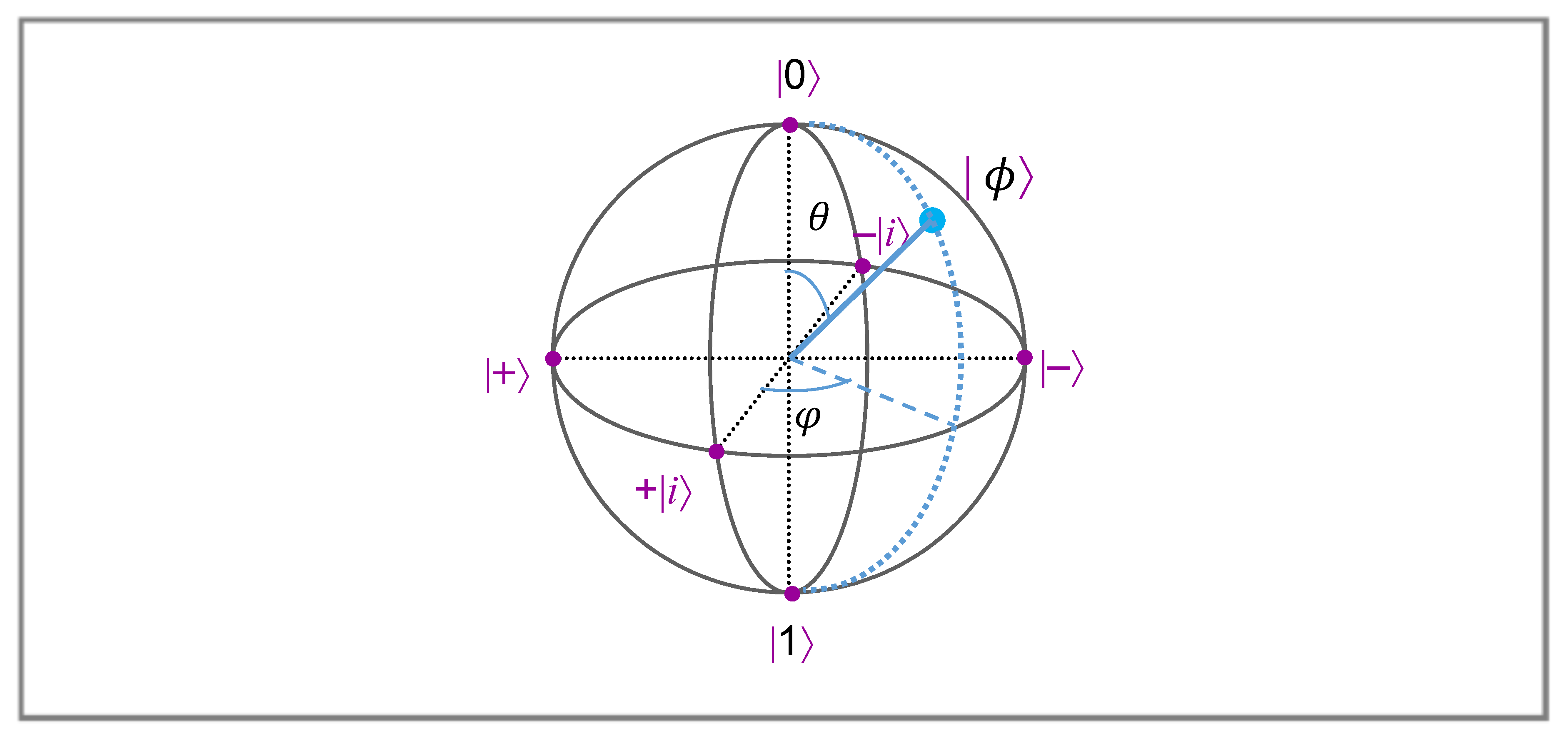
Figure 1. Bloch sphere with the qubit state | ϕ characterized by the angles θ and φ .
Proceedings 02 00152 g001
Figure 2. General arithmetic operation diagram in a qu-trit system.
Proceedings 02 00152 g002
Table 1. The sixteen two-argument logical observables and their truth-tables.
Connective   A ,   B Truth Table {F,T} { 0 ,   1 } Projective {   +   1 ,     1 } Isometric
F a l s e   ;   F   ;   F   F   F   F 0   +   I
N O R F   F   F   T I     A     B   +   A B ( 1 / 2 )   ( + I   U   V U V )
A     B F   F   T   F B     A B ( 1 / 2 )   ( + I U   + V + U V )
¬ A F   F   T   T I     A U
A     B F   T   F   F A     A B ( 1 / 2 )   (   +   I + U V + U V )
¬ B F   T   F   T I     B     V
X O R   ;   A B F   T   T   F A   +   B     2   A B U V   =   Z Z
N A N D   ;   A B F   T   T   T I     A B ( 1 / 2 )   (   I U V + U V )
A N D   ;   A B T   F   F   F A B   =   Π Π ( 1 / 2 )   (   +   I + U + V U V )
A     B T   F   F   T I     A     B   +   2   A B   U V
B T   F   T   F B   =   I Π V   = I Z
A     B T   F   T   T I     A   +   A B ( 1 / 2 )   (     I U   + V U V )
A T   T   F   F A   =   Π I U = ZI
A     B T   T   F   T I     B   +   A B ( 1 / 2 )   ( I +   U V U V )
O R   ;   A B T   T   T   F A   +   B     A B ( 1 / 2 )   (   I + U + V + U V )
T r u e   ;   T T   T   T   T I     I
Publisher’s Note: MDPI stays neutral with regard to jurisdictional claims in published maps and institutional affiliations.