1. Introduction
Cancer is one of the most common and deadly malignant tumors in the world, with hepatocellular carcinoma (HCC) accounting for 80%. Most HCC patients are already in the middle to late stages of diagnosis and miss the optimal treatment time. However, existing diagnostic methods for this disease cannot reveal its dynamic mechanism, and there are also drawbacks such as incurable disease, poor efficacy, significant side effects, and high cost. Thanks to microfluidic technology, this article describes the design and manufacture of a biomimetic capillary network to reproduce the in vitro capillary microenvironment. Finally, the mechanism of cancer cell metastasis through this biomimetic microcapillary network was observed and analyzed.
After cancer cells adhere to the walls of capillaries, they invade into the liver parenchyma tissue, producing liver cancer. This is the process of cancer cell metastasis. Cancer cells must overcome the shear force of blood to adhere to the wall of the capillaries, so the areas with lower shear force are where cancer cells are more likely to adhere. This article investigates the flow velocity and shear force of blood in blood vessels.
Luuk et al. used a microfluidic system to model T cell trafficking, arrest, extravasation and migration to study immunological processes. Tian et al. used 3D printing technology to print microdevices for on-chip toxicity assessment. Maji et al. used a single-step bioprinting technique to simultaneously print a chip platform and developed a perfusable vascularized liver sinusoid in vitro model. Quintard et al. developed a microfluidic platform that enhances organoid growth, function and maturation, by establishing functional perfusable vascular networks. We have noticed that many biomimetic chips currently use printing technology to produce structures. We want to study a more convenient method for manufacturing biomimetic microfluidic chips, so we used a backside lithography combined with laser direct writing method to manufacture semi-circular pipes and verified the feasibility of this method [
1,
2,
3,
4].
2. Flow Velocity of Solution in Channel
For incompressible fluids, the volumetric flow rate
Q in a series of microfluidic channels is constant at any cross-section. The flow velocity ν is defined by cross-sectional area A and volumetric flow rate
Q [
5].
For parallel channels, the pressure drop Δ
P is the same. The volumetric flow rate is defined by the pressure drop and hydraulic impedance
Rh.
The hydraulic impedance is related to viscosity
μ, pipe length
L, and pipe radius
r.
In simulated vascular networks, the cross-sectional area of the direct channels is smaller than the sum of the cross-sectional areas of the thinner parallel channels which is same as in reality where the total cross-sectional area of capillaries is greater than that of the aorta. After analysis, the flow velocity of the solution in the direct channels is greater than that in the parallel channel, and the smaller the cross-sectional area of the parallel channel, the lower the flow velocity of the solution [
6].
For laminar flow in a semi-circular channel, the shear force
τω on the channel wall is related to the liquid flow velocity
ν and pipe radius
r.
So we can conclude that the expression below is correct.
3. Simulation
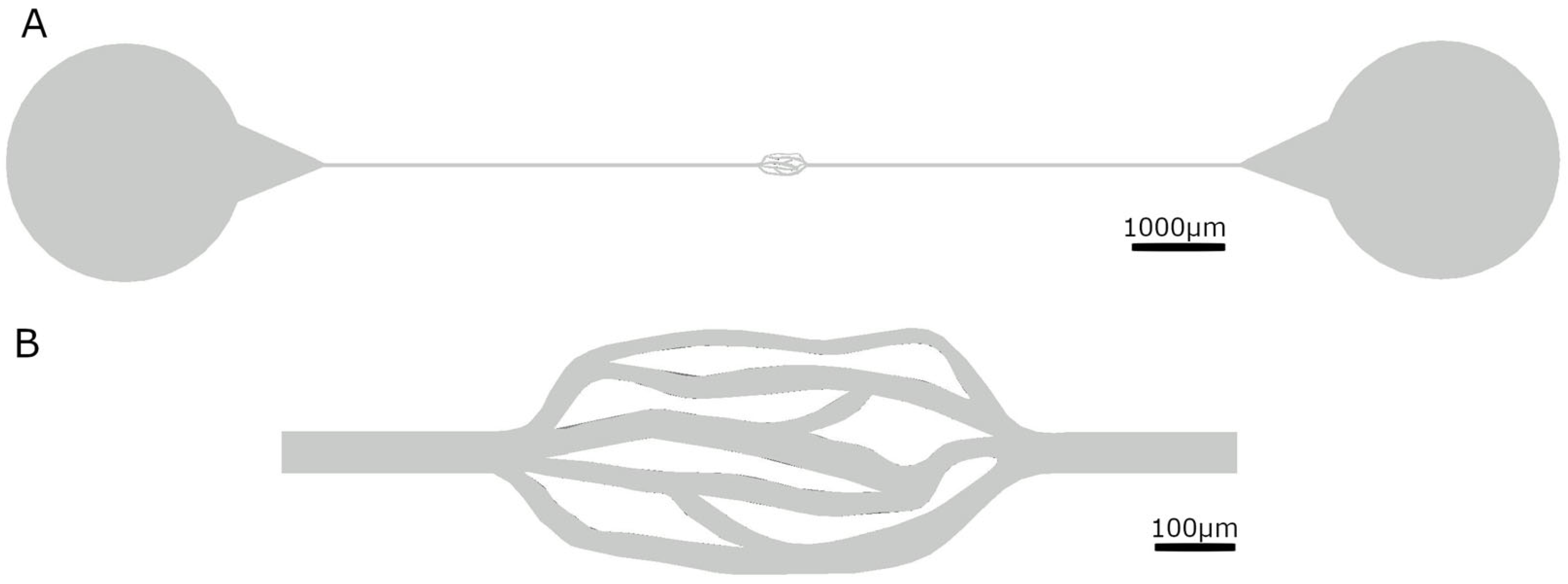
Following our research, we found that the vascular radius of liver capillaries ranges from 2 to 15 μm, whereas the diameter of liver cancer cells is 20 μm. Therefore, the channel height we designed by AutoCAD 2021 is 20 μm, ensuring that cancer cells can pass through, but only through one layer, making them easy to observe. The cross-sectional area of the network channel varies from 240 μm
2 to 480 μm
2, enabling observation of the movement of cancer cells in channels with different cross-sectional areas (see
Table 1 and
Figure 1).
We used COMSOL Multiphysics 5.6 software to simulate the designed microfluidic channels. We set the flow rate at the entrance to 0.0005 m/s. The liquid in the channel is set as blood, and the channel material is PDMS.
Figure 2 shows the simulation of the trajectory of cell movement, flow rate and pressure difference after cells are introduced into the channel. As expected, the liquid flow velocity in the two straight channels is greater than that in the middle network section by a factor of 3 to 10, while the middle complex network section has a roughly classified slower flow velocity in the narrow channel. However, the pressure difference obtained from the simulation differs significantly from that in the physiological situation. This may be due to the use of a two-dimensional model to simplify the simulation, while the real situation is three-dimensional, or it may be due to vascular elasticity, etc. Further research will be conducted in the future.
4. Microfluidic Chip Fabrication
Backside lithography can produce channels with a semi-circular cross-section and a gradual height gradient, making them more biomimetic.
Figure 3 illustrates the difference between backside lithography and UV lithography, where the core of backside lithography is the light diffuser [
7,
8].
Backside lithography can produce channels with a semi-circular cross-section. Using laser direct writing can eliminate the need for a mask template, meaning that modifying the shape does not require the mask template to be remade. We combined the advantages of both techniques to fabricate this microfluidic chip using a combination of laser direct writing and backside lithography.
Similar to the steps in traditional lithography, this method requires only a thin layer of adhesive to be evenly applied to the glass substrate and exposed in addition to ensure that the thick adhesive used to produce the channel does not peel off. We use SU-8 2005 for the thin adhesive and SU-8 3025 for the thick adhesive.
Table 2 below shows some parameters in the manufacturing process.
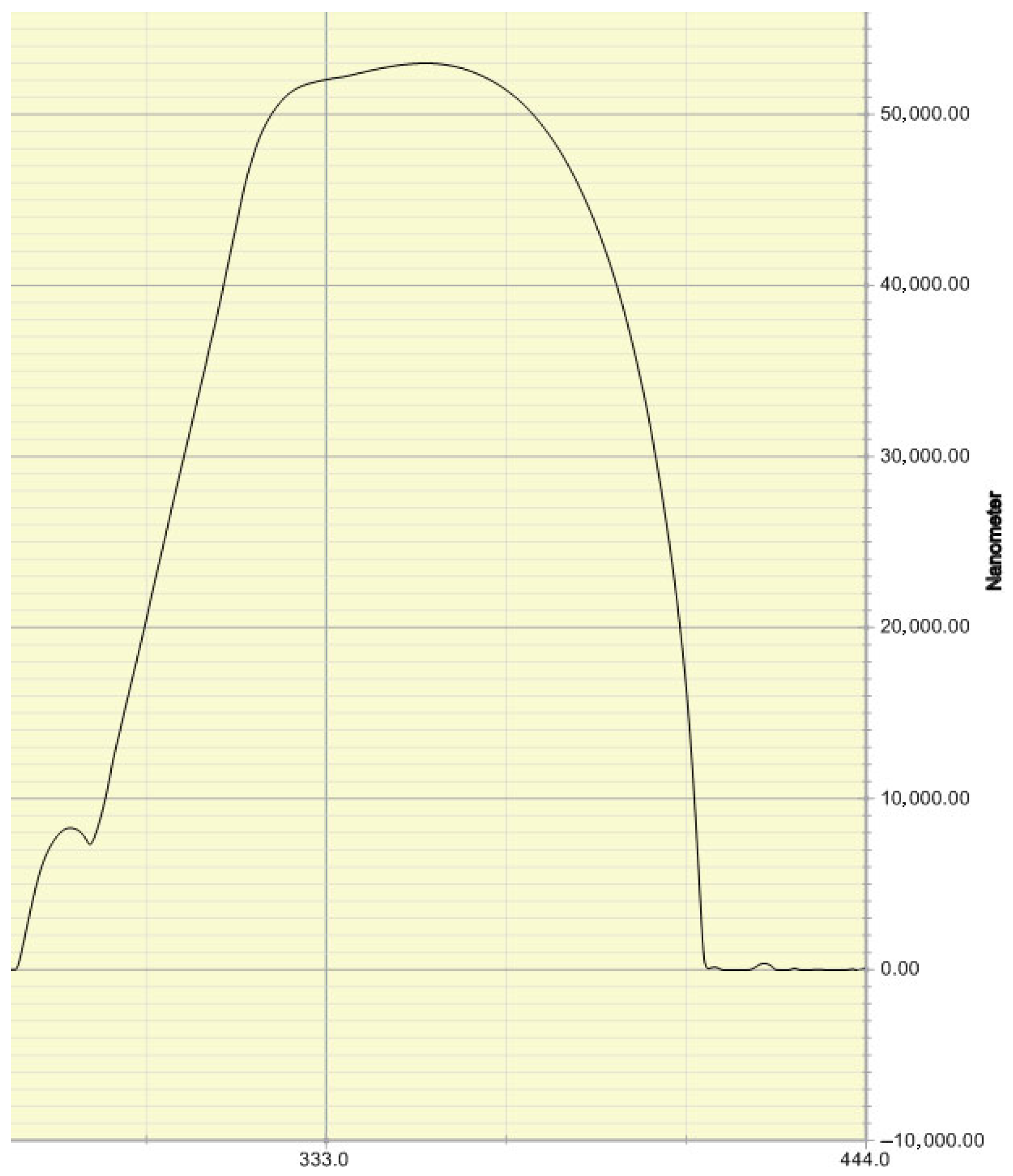
We used a step profiler to verify that the cross-section of the microfluidic channel produced by this method is semi-circular. The measurement results of the step profiler are shown in
Figure 4.
5. Experimental Analysis
The cells we used are A549 lung cancer cells, and the culture medium formula is Ham’s F-12K + 10% fetal bovine serum (FBS) + 1% penicillin streptomycin (P/S). The culture conditions are 95% air and 5% CO2, and the temperature is 37 °C. We take out 0.5 mL of cell solution and pour in 2 mL of phosphate-buffer saline (PBS) before the experiment. The cell concentration is approximately 20,000 cells/mL.
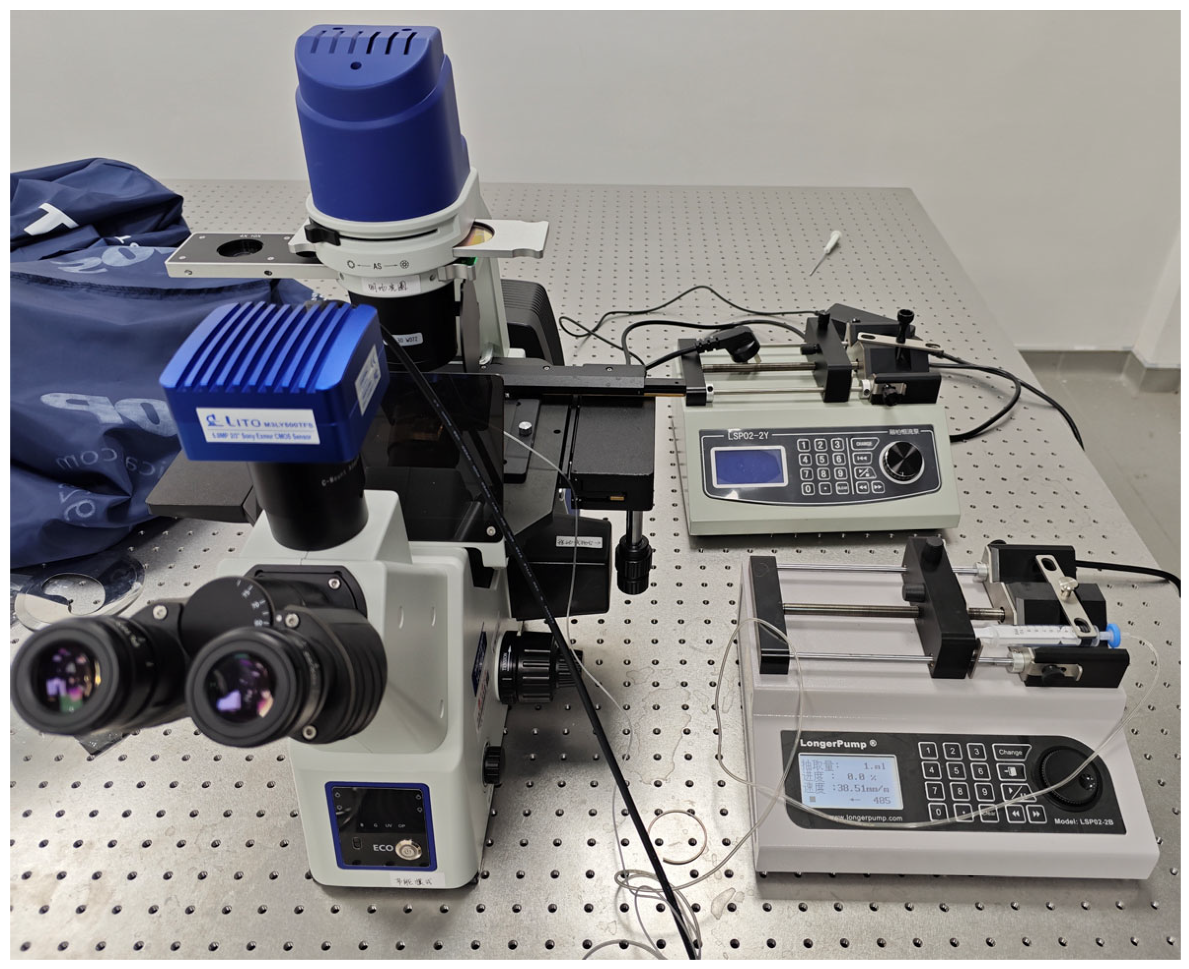
We connected the experimental instruments as shown in
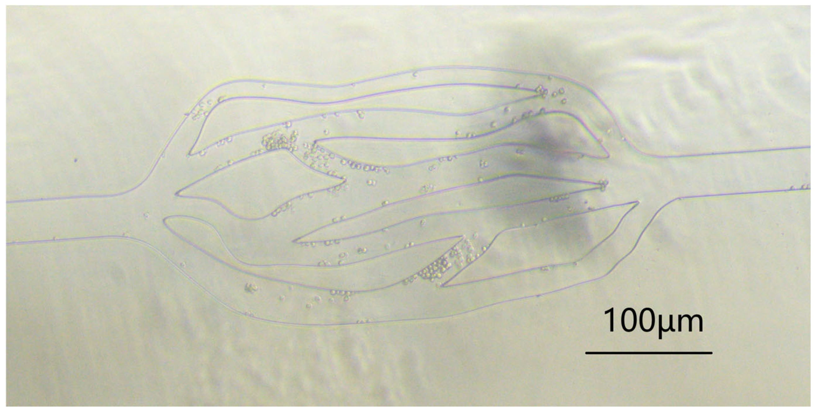
Figure 5. We then dropped a few drops of the above concentration of cell solution at the inlet of the microfluidic channel, and connected a tube at the outlet to extract the liquid using a LongerPump. We observed them through a microscope (see
Figure 6). The experimental results show that the flow velocity of cells in the middle network is much slower than that in the straight channels at both ends.
After repeating the experiments three times with the same parameters as the simulation, we selected several channels with different cross-sectional areas to calculate their average flow velocity. The average flow velocity in a straight channel with a radius of 35 µm was calculated to be 0.00063 m/s, 0.00011 m/s in a 12 µm channel, and 0.00027 m/s in a 28 µm channel. The conclusion is roughly consistent with the simulation results, and the slower the flow velocity in channels with smaller radii, combined with Formula (5), it can be concluded that the shear force in channels with smaller radii is also smaller.
6. Conclusions
Microfluidic technology provides a feasible solution for the in vitro observation and analysis of cell movement and metastasis in blood vessels. This study analyzed simulation and experimental results and concluded that the microfluidic chip can reproduce the in vitro capillary microenvironment, but there are differences in pressure gradient compared to actual human capillaries. We estimate that it is due to the difference between the elasticity of microfluidic channel materials and the elasticity of blood vessels. In the future, we will use different materials to make microfluidic chips to achieve more realistic effects. This work provides practical guidance and experimental environment for future research on the metastasis mechanism of liver cancer cells, and has broad application prospects in the advancement of research and treatment of liver cancer.
Author Contributions
Conceptualization, T.Z., M.Z. and T.X.; software, T.Z.; investigation, T.Z.; writing—original draft preparation, T.Z.; writing—review and editing, T.X.; supervision, T.X. All authors have read and agreed to the published version of the manuscript.
Funding
This research received no external funding.
Institutional Review Board Statement
Not applicable.
Informed Consent Statement
Not applicable.
Data Availability Statement
No new data were created or analyzed in this study. Data sharing is not applicable to this article.
Acknowledgments
This project is supported by National Center for Translational Medicine (Shanghai) Shanghai University Branch under the general program (Ref. SUITM-202414).
Conflicts of Interest
The authors declare no conflict of interest.
References
- de Haan, L.; Suijker, J.; van Roey, R.; Berges, N.; Petrova, E.; Queiroz, K.; Strijker, W.; Olivier, T.; Poeschke, O.; Garg, S.; et al. A Microfluidic 3D Endothelium-on-a-Chip Model to Study Transendothelial Migration of T Cells in Health and Disease. Int. J. Mol. Sci. 2021, 22, 8234. [Google Scholar] [CrossRef] [PubMed]
- Tian, T.; Ho, Y.; Chen, C.; Sun, H.; Hui, J.; Yang, P.; Ge, Y.; Liu, T.; Yang, J.; Mao, H. A 3D bio-printed spheroids based perfusion in vitro liver on chip for drug toxicity assays. Chin. Chem. Lett. 2022, 33, 3167–3171. [Google Scholar] [CrossRef]
- Maji, S.; Lee, M.; Lee, J.; Lee, J.; Lee, H. Development of lumen-based perfusable 3D liver in vitro model using single-step bioprinting with composite bioinks. Mater. Today Bio 2023, 21, 100723. [Google Scholar] [CrossRef] [PubMed]
- Quintard, C.; Tubbs, E.; Jonsson, G.; Jiao, J.; Wang, J.; Werschler, N.; Laporte, C.; Pitaval, A.; Bah, T.-S. A microfluidic platform integrating functional vascularized organoids-on-chip. Nat. Commun. 2024, 15, 1452. [Google Scholar] [CrossRef] [PubMed]
- White, F.M.; Klein, S.A. Fluid Mechanics; McGraw Hill: Columbus, OH, USA, 2011. [Google Scholar]
- Français, O.; Madec, M.; Dumas, N.; Funfschilling, D.; Uhring, W. Basics of Micro/Nano Fluidics and Biology. In Engineering of Micro/Nano Biosystems; Barbillon, G., Bosseboeuf, A., Chun, K., Ferrigno, R., Français, O., Eds.; Springer: Singapore, 2020; pp. 7–87. [Google Scholar] [CrossRef]
- Fenech, M.; Girod, V.; Claveria, V.; Meance, S.; Abkarian, M.; Charlot, B. Microfluidic blood vasculature replicas using backside lithography. Lab Chip 2019, 19, 2096–2106. [Google Scholar] [CrossRef] [PubMed]
- Lee, J.-H.; Choi, W.-S.; Lee, K.-H.; Yoon, J.-B. A simple and effective fabrication method for various 3D microstructures: Backside 3D diffuser lithography. J. Micromech. Microeng. 2008, 18, 125015. [Google Scholar] [CrossRef]
| Disclaimer/Publisher’s Note: The statements, opinions and data contained in all publications are solely those of the individual author(s) and contributor(s) and not of MDPI and/or the editor(s). MDPI and/or the editor(s) disclaim responsibility for any injury to people or property resulting from any ideas, methods, instructions or products referred to in the content. |
© 2025 by the authors. Licensee MDPI, Basel, Switzerland. This article is an open access article distributed under the terms and conditions of the Creative Commons Attribution (CC BY) license (https://creativecommons.org/licenses/by/4.0/).


