Abstract

First Laboratory Measurements of a Super-Resolved Compressive Instrument in the Medium Infrared †

1
IFAC-CNR, Sesto Fiorentino, 50019 Firenze, Italy
2
Dipartimento di Elettronica e Telecomunicazioni (DET), Politecnico di Torino, 10129 Torino, Italy
3
Saitec s.r.l., 50063 Firenze, Italy
4
Fraunhofer IPMS, 01109 Dresden, Germany
5
Centre Suisse d’Electronique et Microtechnique (CSEM), 2002 Neuchâtel, Switzerland
*
Author to whom correspondence should be addressed.
Presented at the 18th International Workshop on Advanced Infrared Technology and Applications (AITA 2025), Kobe, Japan, 15–19 September 2025.
Proceedings 2025, 129(1), 24; https://doi.org/10.3390/proceedings2025129024
Published: 12 September 2025

Abstract

In the framework of the SURPRISE EU project, the Compressive Sensing paradigm was applied for the development of a laboratory demonstrator with improved spatial sampling operating from visible up to Medium InfraRed (MIR). The demonstrator, which utilizes a commercial Digital Micromirror Device modified by replacing its front window with one transparent up to MIR, has 10 bands in the VIS-NIR range and 2 bands in the MIR range, showing a super resolution factor up to 32. Measurements performed in the MIR spectral range using hot sources as targets show that CS is effective in reconstructing super-resolved hot targets.

1. Introduction

Compressive Sensing (CS) paradigm [1,2] allows for the reconstruction of an image using fewer samples than in a classical approach, allowing for the acquisition of a compressed image in a single step. Basically, a CS instrument is composed by a light modulation element (Spatial Light Modulator—SLM) and a single-pixel detector on which the light is concentrated through a lens [3]. Each acquisition (measurement) is given by the product—element by element—between each element of the encoding binary pattern applied to the modulator, the corresponding element of the image focused on it, and the subsequent integration carried out by the condenser on the single-pixel detector. Based on its sparseness, the initial image can be reconstructed by making a number of measurements equal to or less than half of the pixels of the image to be reconstructed [4]. In the framework of the EU project “Super-resolved compressive instrument in the visible and medium infrared for earth observation applications”, we have explored the application of the Compressive Sensing (CS) paradigm for the development of a CS-based instrument operating across the visible (VIS), Near InfraRed (NIR), and Medium InfraRed (MIR) spectral ranges with a focus on improving spatial sampling performance. During the project, we designed and constructed a laboratory demonstrator utilizing a commercial Digital Micromirror Device (DMD) as a central element for implementing a CS architecture. The DMD was modified by replacing its standard front window with one transparent across the entire spectral range from visible to medium infrared. The laboratory demonstrator operates with 10 spectral bands in the VIS-NIR range and 2 spectral bands in the MIR range, enabling CS-based super-resolved acquisitions with resolution enhancement factors of up to 32. Initially, we will present the results from measurements performed in the MIR spectral range using, as targets, small hot sources with an emissivity of 0.75 and maximum temperature of 843 °C. The experimental results demonstrate that CS is effective in reconstructing super-resolved hot targets.

2. Materials and Methods

The SURPRISE demonstrator was conceived as a whiskbroom spectral imager with 2 channels in MWIR (3–5 micron) and 10 channels in VIS-NIR (400–900 nm) spectral ranges (see Figure 1). The scene is scanned along two axes by means of a scanning system. The fore-optics provides the image of the observed portion (target) of the scene on the image plane field stop at which a SLM (a reworked DMD DLP7000 by Texas Instrument, Dallas, Texas, USA) is placed. The image captured in the instrument’s Instantaneous Field Of View (IFOV) corresponds to a “macropixel” on the SLM. Spectral splitting is applied after the SLM-based coding stage by means of dichroic mirrors and is followed by the spatial integration stage implemented by the condensers. The signal is further spectrally filtered (or dispersed by the spectrometer for the VIS-NIR channels) and finally acquired in spectral bands of interest by suitable detectors. The demonstrator is completed with an additional block constituted by a high-resolution camera, which will be used for alignment and validation purposes. The main characteristics selected of the demonstrator are listed in the following table.
It is worth noting that none of the DMD models from Texas Instruments (Texas Instrument, Dallas, TX, USA) is compatible with the required large spectral range for the demonstrator’s operation. Thus, DMD DLP7000 (Texas Instrument, Dallas, TX, USA) was reworked by replacing the original borosilicate window with an uncoated window presenting high transmittance over the VIS-NIR and MIR spectra [5]. Moreover, the DMD is tilted 45° around the z-axis (named z-axis due to the direction of incidence of the rays on the DMD). Such a configuration allows for the optical elements to be disposed on the same horizontal plane. The need for mounting the DMD rotated is due to the fact that the DMD micromirrors of DLP®7000 (Texas Instrument, Dallas, TX, USA) have a diagonal tilt axis. As a consequence, a generic multi-target scene has to be scanned along a couple of orthonormal axes lying parallel to the diamond sides, i.e., tilted 45° with respect to the plane on which the demonstrator lies. The following figure shows the demonstrator scheme, the target bench with a target use for acquisition in the VIS-NIR spectral range, and the target used for measurements in the MIR spectral range. In Table 1 parameters for the laboratory setup of the SURPRISE demonstrator are reported.
Figure 2 shows the infrared image of the MIR target acquired by using a thermal camera. The yellow-marked area corresponds to a macro-pixel acquired by the demonstrator. The macro-pixel contains six MIR sources.
The MIR sources are IR lamps with emissivity equal to 0.75 and a maximum temperature—measured with a thermocamera—of 843 °C. Two different levels of SNR were implemented on the MIR channels: Channel#1 at 3.3. μm featured a higher noise level (electronics parameters were not optimized), whereas Channel#2 @4.0 μm featured very good SNR. The SNR was evaluated on the super-resolved macro-pixel image reconstructed (without CS) by applying a sequence of subsequent, single-pixel ON masking for the two MWIR channels, with SR ranging from 4 × 4 to 32 × 32. The results are reported in Table 2.
Concerning CS acquisition, two methods were used for reconstructing the images, the classical TV method and the ISTA-Net method, which is based on machine learning paradigm [6].

3. Results

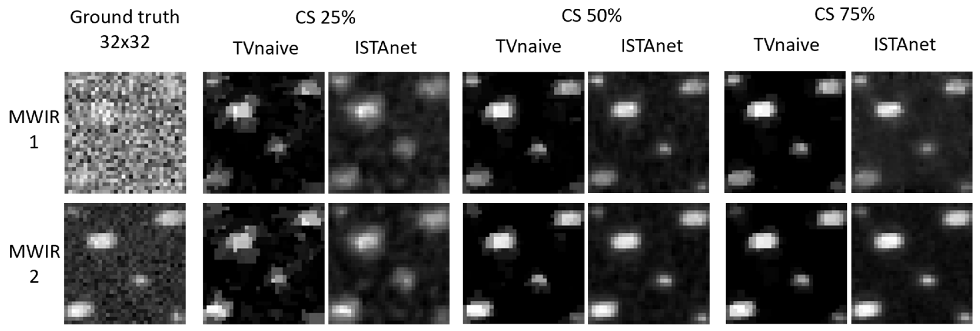
Figure 3 shows that CS reconstruction works well at reconstructing the targets. It can be clearly seen that there is a denoising effect achieved by the ISTA-Net and TV methods.
The reconstruction quality is generally good for the TV method while for the ISTA-Net method, the performance is worse. In particular, the ISTA-net method passes all tests at CR of 50% and 75% for all SR factors, and it passes the test at CR of 25% for the 16 × 16 and 32 × 32 SR factors. Performed measurements show a denoising effect which tends to provide reconstructions that are “cleaner” than the ground truth images at CR equal to 50% and higher. Denoising effect was observed in the case of low-SNR MIR channel by applying the ISTA-Net and TV methods.

4. Conclusions

The SURPRISE demonstrator was successfully tested in all spectral channels from VIS-NIR to MIR. Concerning the MIR target, the reconstruction quality is generally good for the TV method while for the ISTA-Net method, the performance is generally worse. In general, MIR measurements show a denoising effect, which tends to reduce the graininess of the reconstructed image.

Author Contributions

Conceptualization, V.R., E.M., D.G. and V.N.; methodology, S.F.G., C.P. and C.L.; software, L.P., D.V. and T.B.; validation, D.G., L.P., M.C. and C.P.; formal analysis, S.F.G., T.B., C.L. and L.P.; resources, M.C., S.F.G. and C.P.; data curation, C.L.; writing—original draft preparation, D.G., V.R., V.N., S.F.G., E.M., C.P. and M.C.; writing—review and editing, D.G.; supervision, V.R.; project administration, V.R.; funding acquisition, V.R. All authors have read and agreed to the published version of the manuscript.

Funding

This research was funded by the European Union’s Horizon 2020 research and innovation program under Grant Agreement No 870390.

Institutional Review Board Statement

Not applicable.

Informed Consent Statement

Not applicable.

Data Availability Statement

The raw data supporting the conclusions of this article will be made available by the authors on request.

Conflicts of Interest

Author Marco Corti was employed by the company Saitec s.r.l. The remaining authors declare that the research was conducted in the absence of any commercial or financial relationships that could be construed as a potential conflict of interest.

References

  1. Candes, E.J.; Wakin, M. An introduction to compressive sampling. IEEE Signal Process. Mag. 2008, 25, 21–30. [Google Scholar] [CrossRef]
  2. Donoho, D.L. Compressed sensing. IEEE Trans. Inf. Theory 2006, 52, 1289–1306. [Google Scholar] [CrossRef]
  3. Duarte, M.F.; Davenport, M.A.; Takhar, D.; Laska, J.N.; Sun, T.; Kelly, K.F.; Baraniuk, R.G. Single-Pixel Imaging via Compressive Sampling. IEEE Signal Process. Mag. 2008, 25, 83–91. [Google Scholar] [CrossRef]
  4. Candes, E.; Romberg, J. Sparsity and incoherence in compressive sampling. Inverse Probl. 2007, 23, 969. [Google Scholar] [CrossRef]
  5. Borque Gallego, G.; Giriens, L.; Ummel, A.; Roulet, J.C.; Guzzi, D.; Raimondi, V.; Pache, C. Front-window replacement and performance characterization of a commercial digital micro-mirror device for use in the infrared spectrum. In Proceedings of the International Conference on Space Optics—ICSO 2022, Dubrovnik, Croatia, 3–7 October 2022. [Google Scholar] [CrossRef]
  6. Magli, E.; Bianchi, T.; Guzzi, D.; Lastri, C.; Nardino, V.; Palombi, L.; Raimondi, V.; Taricco, D.; Valsesia, D. Compressive imaging and deep learning based image reconstruction methods in the “SURPRISE” EU project. In Proceedings of the European Workshop on On-Board Data Processing (OBDP2021), Online Event, 14–17 June 2021. [Google Scholar]
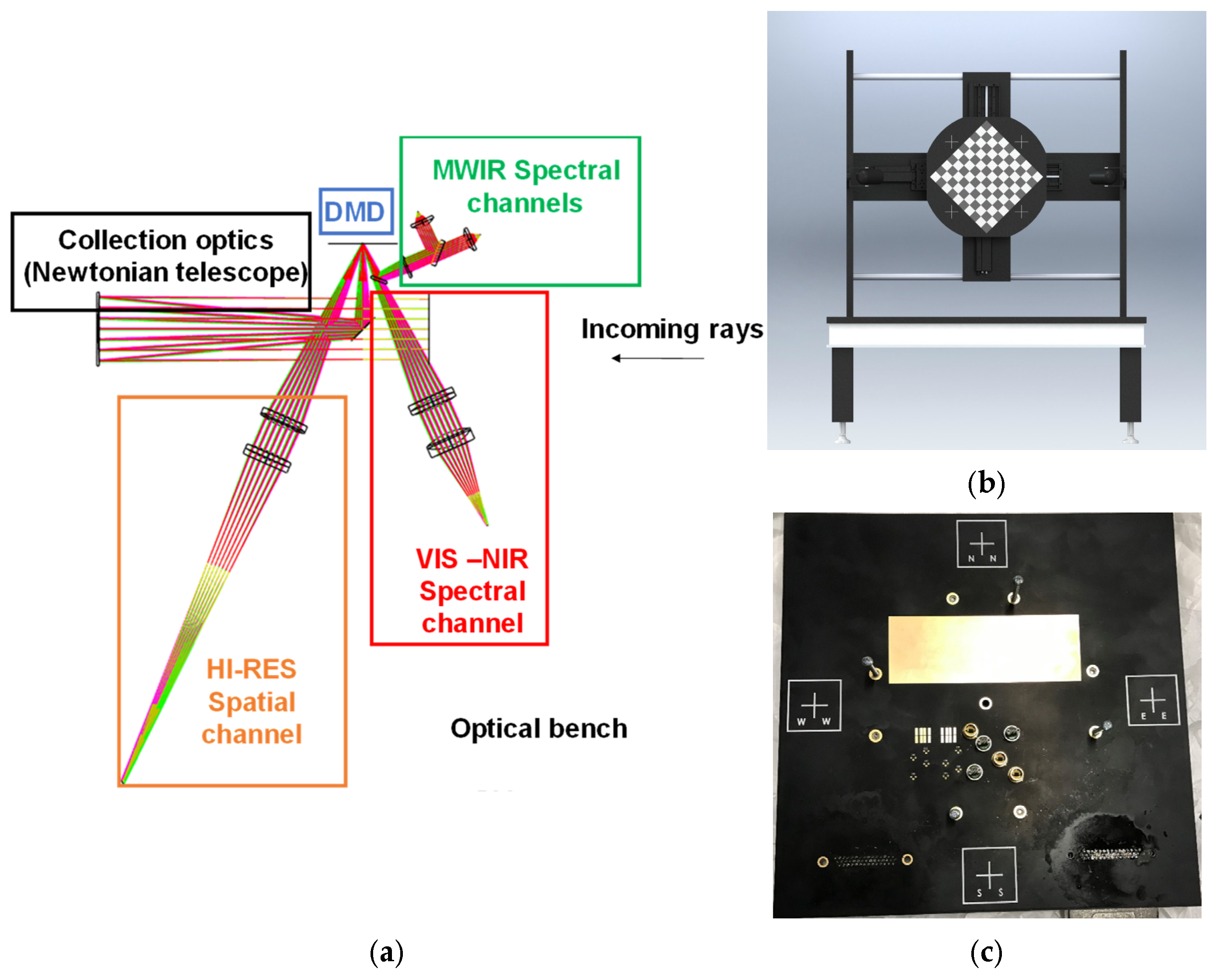
Figure 1. (a) Scheme of labortaory demostrator, (b) target scanning system, and (c) target used for mesuements in MIR spectral range.
Proceedings 129 00024 g001
Figure 2. An infrared image of the target that shows the number of IR sources on the target.
Proceedings 129 00024 g002
Figure 3. An infrared image of the target that shows the number of IR sources on the target and CS reconstruction of the spatially super-resolved image of a macro-pixel for the two MIR channels with SR equal to 32 × 32.
Proceedings 129 00024 g003
Table 1. Selected parameters for the laboratory setup of the SURPRISE demonstrator.
Optical Parameters for the Laboratory Setup of SURPRISE Demonstrator
ParameterValue
Target dimensions (mm)30 × 30
Target to lens distance (mm)6346
Collection optics focal length (mm)350.0
Collection optics focal ratio (F/#)4.605
FOV (degrees)0.2708 × 0.2708
SLM typeDMD DLP®7000
Micromirrors pitch (μm)13.68 × 13.68
DMD area of interest (macro-pixel)128 × 128 micromirrors (binned 4 × 4)
Maximum nominal super-resolution32 × 32
Image (macro-pixel) side on DMD (mm)1.751 (13.68 μm × 128 pixels)
Lens to image distance (mm)370.4
Image dimensions (side) on DMD (mm)1.751 × 1.751
Image diameter on MWIR detectors (mm)<1.0
Image dimensions (side) on VIS-NIR channel fiber entrance plane (mm)<1 (ensquared energy > 95%)
Table 2. SNR evaluated for different SR values ranging from 4 × 4 to 32 × 32.
SNRSR 4 × 4SR 8 × 8ST 16 × 16SR 32 × 32
Channel #1851.4<1
Channel #27030142.5
Disclaimer/Publisher’s Note: The statements, opinions and data contained in all publications are solely those of the individual author(s) and contributor(s) and not of MDPI and/or the editor(s). MDPI and/or the editor(s) disclaim responsibility for any injury to people or property resulting from any ideas, methods, instructions or products referred to in the content.