Abstract
Radial turbines’ preliminary designs are usually carried out through some dimensionless approaches, such as the loading-to-flow-diagram and/or the blade speed ratio. In case of variable nozzle radial turbines, multi-points specifications must be considered, related to the improvement of the operating range. As preliminary design correlations and standards usually taken into consideration arise from studies dedicated to fixed geometry radial turbines, they need to be updated with regard to nozzle off-design opening configurations. This paper provides some theoretical basics in order to help designers considering variable geometry problems. Some complementary elements about the dimensionless methods are given by taking into account the nozzle opening effect. Then, useful considerations are brought regarding the preliminary design of variable geometry radial turbines with multi-points specifications.
1. Introduction
Radial inflow turbines are currently employed in many industrial applications, such as automotive turbochargers, cryogenics or air-conditioning systems. In addition to their relatively low-cost manufacturing and compactness, they provide a specific mass flow and a rotational speed for a given pressure expansion. Reaching high pressure-ratios for acceptable efficiencies is also possible. Both the flow pattern and the behaviour of such centripetal turbines are described especially by Moustapha et al. [1] and Baines [2]. As a broadening of the operating range sometimes becomes necessary for specific applications, variable nozzle geometry can be implemented. The case of automotive turbochargers with variable geometry is then largely discussed in the literature. Regarding the aeronautic field, the improvement of the operating range provided by this technology forecasts the development of a new architecture of Environmental Control Systems (electrical system). However, it makes the design more challenging because the variable geometry turbine stage efficiency must be acceptable for a wide operating range. To do so, the turbine stage should be designed directly from a multi-points specification, for which the first order information is sometimes difficult to extract.
To cope with such a challenge and keep track of physical considerations in the process, several preliminary design steps and classical processes must be adapted. Indeed, even if the results from these first design steps are not absolutely accurate in all respects, they provide useful trends, key turbine dimensions and a first idea of the performance. As noticed by Chen and Baines [3], the more the design can be optimized in the early stages, the less time will be wasted in later investigations. Preliminary design recommendations and processes for radial turbines are brought especially by Whitfield and Baines [4]. Then, useful suggestions with regard to the whole stage design allow for ensuring the good performance of the stage. To go further, an integrated design approach is proposed by Baines [5]. This preliminary design procedure details the several steps that have to be led during the design of a radial turbine stage, including recommendations about deviation, blockage and stage losses.
A useful starting point of the design process entails specifying dimensionless coefficients representative of the stage behaviour such as the classical specific diameter to specific speed map (-). Correlations (Balje, [6]) enable sizing the rotor directly from operating conditions (see Figure 1).
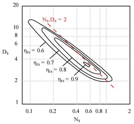
Figure 1.
- map correlations. These data are extracted from Balje [6] and redrawn by the authors.
Another classical approach deals with the choice of a blade speed ratio in order to match the rotational speed of the machine to the value of the pressure ratio. For radial turbines, an optimum value is obtained for a ratio close to 0.7 (Baines and Chen, [7]). More generally, the optimum blade speed ratio corresponding to the peak efficiency point is approximately related to the rotor inlet absolute and relative flow angles. This characteristic is exploited for mixed flow turbines especially by Rajoo and Martinez-Botas [8,9] and also for radial turbines through the implementation of back or forward swept rotor blading to improve off-design performance. The latter is discussed for instance by Barr et al. [10,11] and Huang et al. [12]. The third classical dimensionless approach is the loading-to-flow-diagram (-). Again, it provides from operating conditions a first rotor geometry with good efficiency expectations. Moustapha et al. [1] state that these three mentioned approaches are equivalents. Therefore, designers remain free to choose the best approach with respect to their various constraints and data.
Regarding the - formalism, fundamental contributions are provided by Chen and Baines [3,13]. The first paper proposes an analytical optimization design, in order to obtain the best possible efficiency by reducing the losses of the stage. It actually involves reduction of the ratio between the relative velocity and the blade speed at the rotor inlet (). The second paper brings correlations found empirically between the blade loading coefficient, the flow coefficient and the expected total-to-static isentropic efficiency. The data from some 40 turbines tests taken from a variety of sources, plotted in this way, are sufficiently well correlated to allow contours of efficiency to be drawn on the map (see Figure 2). These indicate clearly that the region of peak efficiency exists at flow coefficients in the range [0.2; 0.3] and loading coefficients in the range [0.9; 1.0]. This fundamental map is still currently widely used during the preliminary design of a radial turbine.
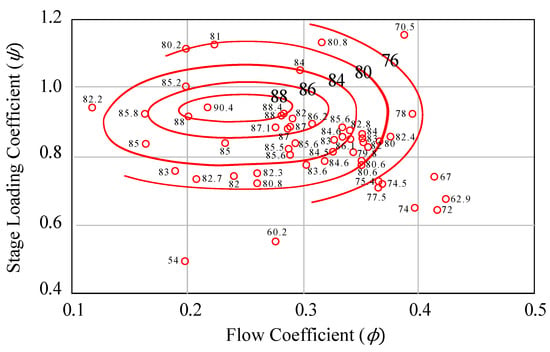
Figure 2.
Loading-to-flow (-) diagram correlations. These data are extracted from Chen and Baines [13] and redrawn by the authors.
What emerges from these two studies is that the optimum range of loading coefficients is directly linked to the value of the relative angle at the rotor inlet. A consensus of [−40°; −20°] for is commonly admitted in the literature to be an optimal range. It is largely confirmed especially by Woolley and Hatton [14] and Spence and Artt [15]. In addition, optimum flow coefficients are restricted to a short range of values. It is mainly due to the fact that the rotor exit velocity losses increase for higher values of , while smaller flow coefficients may increase the turning flow and then the internal losses.
Both the loading-to-flow-diagram and the blade speed ratio approaches are well established in cases of fixed geometry radial turbines for efficient preliminary designs. However, the best performance is reached for the specification, to the detriment of off-design operating points. In case of variable nozzle radial turbines, multi-points specifications are generally considered. The classical preliminary design process needs to be adapted, since preliminary design correlations and standards usually taken into consideration arise from studies dedicated to fixed geometry radial turbines. This adaptation is required not only for defining the most interesting specification for the rotor (which is a fixed geometry device), but also to optimise the performance of the stage to its final system requirements. A careful definition of the multi-points specification must be conducted and a hierarchy in the operating regions decided.
To date, from the best knowledge of the authors, such considerations are not available. Hence, the aim of this paper is to provide some theoretical basics in order to help designers considering variable geometry problems. The overall approach is in the continuity of the work presented by Chen and Baines [3,13], together with the observations presented in Binder et al. [16] and Carbonneau and Binder [17] concerning the signature of geometry variation in the characteristic line of the stage plotted in a - map. Those theoretical basics are presented in the following part of the paper and some elements of validation are then proposed.
2. Adaptation of the Blade Speed Ratio Method: Simplified Approach
2.1. Theoretical Issues
The following theoretical development refers to turbine wheel velocity triangles defined in Figure 3:
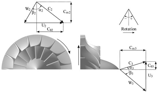
Figure 3.
Velocity triangles at both turbine wheel inlet and outlet.
From any nozzle geometry, one can estimate the stator outlet absolute flow angle by the use of the sine rule from Moustapha et al. [1]. The latter is based on Figure 4 and Equation (1):
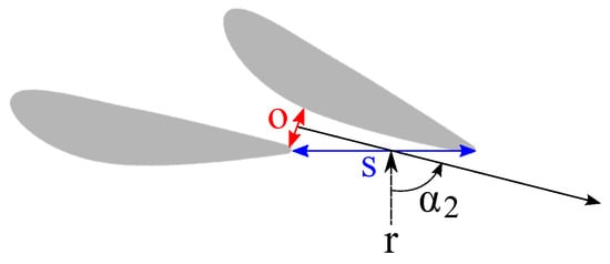
Figure 4.
Estimation of by the sine rule.
Moreover, a simple relation between the loading coefficient and the flow angles is found from Figure 3, if the outlet swirl is neglected:
Furthermore, then:
Thus:
By definition of the isentropic velocity :
To go further, one can assume that an optimum of total-to-static stage efficiency is reached for a given relative angle at the wheel inlet , which depends on the rotor design (in the present paper, the value of −30° is selected for generic illustration, since it is at the center of the expected optimal range). This leads to the next relation:
For each stator outlet flow angle, one can find an optimal value of the blade speed ratio which allows for reaching the maximal stage efficiency. In addition, from any value, it is possible to deduce the corresponding stator opening angle value thanks to the sine rule applied on the variable nozzle geometry. Thus, this very simplified approach gives trends of the evolution of , which provides the best reachable stage efficiency as the stator opening position is modified.
2.2. Sensitivity Study
The illustration of Equation (7) is proposed in Figure 5 for different values of inside the usual optimal range:
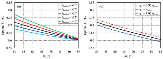
Figure 5.
(a) Sensitivities to the optimal relative angle (plotted for = 0.7); (b) Sensitivities to the maximal efficiency (plotted for = −30° and = 0.7).
For a given value of , with respect to the reference case ( = −30°), the largest discrepancy in terms of optimal is obtained for the lowest stator outlet flow angle. It reaches a relative error of 6.9% if = −40°. In addition, for a fixed optimal relative angle, an error of 5% on the maximal stage efficiency would imply a relative error of 2.6% on the optimal value. In addition, both of these sensitivities with regard to the reference case are probably additive. According to these discrepancies, one can emphasize that the value has a weak impact on the optimal blade speed ratio for closed nozzle configurations (typically high values of ). This means that the optimal range is narrow for these configurations: a low flexibility is available in terms of adaptation between the rotational speed, the stage pressure-ratio and the inlet total temperature. These configurations are then very sensitive to off-design operation, while a larger flexibility seems available for open configurations (typically low values of ). Furthermore, these curves show a general trend with respect to the stator outlet flow angle. Indeed, for open stator configurations, the optimal blade speed ratio tends to reach higher values than 0.7, while an opposite behaviour is observed for closed stator configurations. As the blade speed ratio approach is equivalent to the loading-to-flow diagram method, variations for the optimal blade speed ratio due to the variable nozzle vane angle should be expressed in a - map by the displacement of the optimal target region.
3. Adaptation of the Loading-to-Flow Diagram Method: Simplified Approach
According to Chen and Baines [3], the internal losses in the rotor passage are some function of the mean velocity of the fluid relative to the passage (due to entropy creation through friction at the wall; see Denton [18]), and can be thus minimized by reducing the inlet relative velocity to a limiting value. This consists in reducing the ratio , expressed by the authors as follows:
Moreover, according to Chen and Baines [13], the meridional component of velocity through a turbine rotor is usually nearly constant:
In addition, by definition of the flow coefficient :
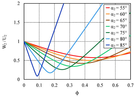
Figure 6.
Evolution of as a function of and (adapted from Chen and Baines [13]).
The graph illustrates the strong influence of the stator outlet flow angle over the decrease of the internal rotor losses. It modifies both the level of and the optimal flow coefficient range. For closed stators (high values), the internal rotor losses are minimal for low values of flow coefficient; the optimal range is narrow. For open configurations (low values), the rotor internal minimization of is less sensitive to the flow coefficient. Optimal target zones are significantly larger for these openings but are accompanied by higher values of . This explains in particular why typical values of fixed geometry stator exit flow angles are in the range [65°; 75°] (according to Chen and Baines [13]), and why it is generally harder to reach a high total-to-total stage efficiency with a full open nozzle configuration. In other words, open configurations tend to be less efficient but more tolerant to off-design operation than the closed ones.
Regarding the efficiency issue, the total-to-static definition is often the primary consideration for radial turbines. If such is the case, the dynamic pressure loss at the exit of the stage needs to be brought in the discussion. High flow-coefficient configurations (in conjunction with low loading) will suffer this additional penalty. However, this should not alter the general conclusions drawn from the diagram analysis.
According to these previous considerations, in addition to the strong link between the loading coefficient and (highlighted by Equation (7)), one can define an optimal - region with respect to the stator outlet flow angle. To do so, an optimal region is built such as the loading coefficients corresponding to values included inside the optimal range [−40°; −20°]. In addition, for a given stator outlet flow angle, one can determine an optimal flow coefficient range such as the ratio would be lower or equal to 0.6. This value of 0.6 is selected for the clarity of the figures, so that the most opened configurations can be represented. However, this choice induces some large optimal flow coefficient ranges especially for relatively open cases, but it presents interesting trends. The procedure is applied for different absolute flow angles and results are shown in Figure 7:
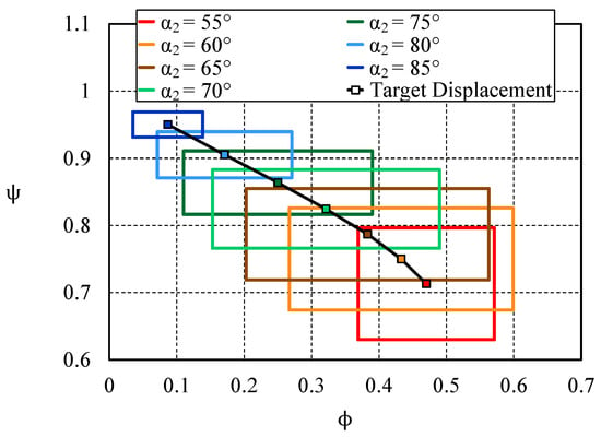
Figure 7.
Target zones of preliminary design in a - map, with reference to the stator outlet flow angle .
The size of these target zones clearly varies when is modified. This is a consequence of the procedure previously described, based on both Equations (7) and (11). When the nozzle opening increases (i.e., decreases), the trajectory of these optimum regions tends to higher values of ([0.45; 0.5]) and to lower values of , and vice-versa. In addition, for a nozzle outlet flow angle of 75°, a relatively good agreement is found with respect to Chen and Baines [3,13] correlations.
4. Test Cases
These simplified theoretical approaches directly bring trends which could be used during the first steps of a radial turbine design. Global performances data, both numerical and experimental, would allow to confirm these trends. Therefore, two turbines are considered:
- A baseline radial turbine geometry from Liebherr-Aerospace (LTS) called MST. The rotor inlet diameter is around 150 mm. Then numerical means and computational fluid dynamics (CFD) results are provided. The CFD model is restricted to one passage stator-rotor per row. The 3D Reynolds-Averaged Navier–Stokes (RANS) mixing-plane computations are performed with FINETM/Turbo developed by NUMECA (V10.2, Brussels, Belgium). The chosen turbulence model is the one Equation Spalart–Allmaras model. The mesh size is around eleven million points and ensures that values are strictly lower than five. For more details about the turbine geometry and the whole numerical set up considered, see Roumeas and Cros [19].
- A radial turbine from automotive application called PTM. The rotor inlet diameter is around 50 mm. Experimental results are provided by ISAE-SUPAERO through a test rig dedicated to turbocharger application. Global performances are then characterized thanks to steady measurements applied at both the inlet and the outlet of the turbine stage. For more details about the turbine geometry and the whole experimental test rig, see Binder et al. [20].
In order to isolate the stator opening effects with regard to the preliminary design methods presented above, there is no nozzle endwall clearance considered here. In addition, three opening configurations are investigated for both turbines. Their corresponding nozzle vane outlet angle and estimated stator outlet flow angle values are detailed in Table 1.

Table 1.
Opening configurations for both turbines.
Then, dimensionless total-to-static efficiency evolutions are plotted in Figure 8 with reference to the blade speed ratio:
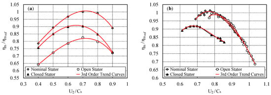
Figure 8.
Evolution of the dimensionless total-to-static efficiency with regard to the blade speed ratio. (a) computational fluid dynamics (CFD) results for the MST turbine; (b) experimental results for the PTM turbine.
Concerning the MST CFD results, the best efficiency is obtained for a blade speed ratio value close to 0.7 whatever the opening configuration considered. These curves are not enough discretized with respect to to catch any displacement of the optimum ratio to higher values for the full open case, or to smaller values for the closed case. However, associated third order trend curves suggest such a variation. With reference to the PTM experimental results, the amount of available data is sufficient to confirm these trends. Indeed, when the nozzle vane outlet angle moves from 67.1° to 75.4°, and finally to 79.4°; the optimum blade speed ratio values are, respectively, about 0.8, 0.77, and 0.68.
5. Results and Comparisons with Both Theoretical Approaches
Experimental data from the PTM turbine can be exploited for comparisons with both theoretical and - map approaches. The experimental evolution of the optimum blade speed ratio with respect to the stator outlet flow angle is shown in Figure 9:
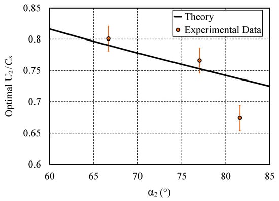
Figure 9.
Comparison between the theoretical approach and experimental data available for the PTM turbine. The theoretical curve is plotted for = −30° and = 1.
The ideal stage efficiency ( = 1) is considered for building the theoretical curve. A maximal efficiency value is then theoretically reachable over the stator opening range by adjusting . This efficiency value is configuration dependent and will generally drop once the stator opening moves away from the nominal position, as shown above. Despite the extreme simplification of this theoretical approach, a good agreement with the experimental data is obtained for both nominal and open stator configurations. However, some discrepancies appear for the closed stator configuration, for which the sine rule might be less suitable. In general terms, the trend is relatively well caught by the theoretical curve.
To show how these simplified approaches prove to be helpful for the preliminary design, especially with respect to the “ system constraints ” illustrated by the matching of the turbine to a compressor, let us consider the results proposed in Figure 10. Three constant pressure-ratio lines are plotted for three different opening configurations of the nozzle, together with their corresponding optimal operating regions (based on values). Those specific lines are operating lines for which the pressure-ratio is constant. The linearity of a constant pressure-ratio line in a loading-to-flow diagram is presented by Binder et al. [16] and Carbonneau and Binder [17]. This formalism is adapted to variable geometry problems since the slope of a constant pressure-ratio line is related to the stage pressure-ratio and the nozzle opening. The scatter represents the operating range allowed by the matching with the compressor. This representation clearly shows that the overall design tends to favour the closed configurations to the detriment of the opened ones. This might or might not have been the initial choice of the designer, who can correct the design if necessary (adaptation of the diameters, modification of the loading device, etc.) and also have a clear representation of the consequences on the whole operating range.
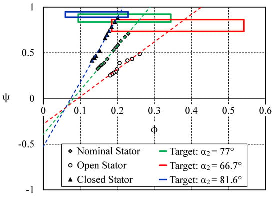
Figure 10.
Loading-to-flow (-) map theoretical approach applied to experimental data available for the PTM turbine.
To go further in the discussion, it appears that, for the closed stator configuration, the operating point on the border of the optimal range does not correspond to the best efficiency point plotted in Figure 8. This theoretical optimal range seems to be a bit biased, probably because of the approximation of Equation (3) for which the outlet swirl is neglected and can be high for extreme off-design conditions. However, the lack of precision is not that big an issue at this step of the design for which the first order influences are tracked. For example, the trends to enhance the efficiency for open configurations (if those operating regions prove to be critical for the overall system) are clear: a global move toward higher flow coefficients is necessary, for which the consequences on the other opening configurations will have to be evaluated. However, this consideration in itself is not sufficient. Indeed, Figure 6 shows that the relative velocity will still be high and will penalize the efficiency. Further refinement to the rotor geometry is then required, probably in the prospect of decreasing the wet surface. This points out that a variable geometry stage cannot be efficiently designed by using only fixed geometry stage classical procedures. Information such as found in Figure 6 and Figure 7 will hopefully help catch the good trends, in order to match the system constraints.
6. Conclusions
To cope with the challenging design of a variable geometry radial turbine with multi-points specification, several preliminary design steps and classical processes must be adapted. To do so, this paper provides some theoretical basics in order to help designers considering variable geometry problems. Simplified approaches have been proposed to update both the loading-to-flow diagram and the blade speed ratio methods. The nozzle endwall clearance is not taken into account, in order to isolate the stator opening effects. With regard to the blade speed ratio, the classical optimum ratio close to 0.7 tends to higher values of for open stator configurations, whereas it tends to lower ratio values for closed configurations. This opening effect also modifies the optimal target region in a - map. More precisely, for an open stator configuration, this optimal zone tends to higher values of and to lower values of . An opposite trajectory is also observed when the nozzle opening decreases. In addition, this paper shows that open nozzle configurations tend to be less efficient but more tolerant to off-design operation than the closed ones. These considerations are useful for designers to understand variable geometry problems and also to choose some efficient specification regions.
To keep up this preliminary design, one could take on board the nozzle endwall clearance. Indeed, the present paper is a first step which isolates the stator opening effects from any technological effects related to the clearance implementation. However, this nozzle endwall clearance directly impacts the turbine stage behaviour and leads to an efficiency drop, especially for high loaded configurations (closed nozzle cases). Thus, further works are necessary to bring a complete approach taking into account both the opening effect, the nozzle endwall clearance impact and their interaction. Those considerations would influence the choice of the specified operating points and their hierarchisation.
Author Contributions
Conceptualization, P.T.L. and N.B.; Methodology, P.T.L. and N.B.; Software, P.T.L.; Validation, N.B. and X.C.; Formal Analysis, P.T.L., N.B., S.C. and M.R.; Investigation, P.T.L., N.B., S.C. and M.R.; Writing—Original Draft Preparation, P.T.L. and N.B.; Writing—Review and Editing, P.T.L.; Visualization, P.T.L., N.B., S.C., M.R. and X.C.; Supervision, N.B., S.C., M.R. and X.C.; Project Administration, N.B., S.C., M.R. and X.C.; Funding Acquisition, N.B., S.C., M.R. and X.C.
Funding
The authors wish to thank Liebherr-Aerospace Toulouse SAS and the French Ministry of Higher Education and Research for the financial support. The authors are also thankful to Renault and the French Industry-Research Consortium in Turbomachines (CIRT) for their additional funding.
Acknowledgments
The authors acknowledge ISAE-SUPAERO for providing experimental data and numerical means used for this study.
Conflicts of Interest
The authors declare no conflict of interest.
Abbreviations
The following abbreviations are used in this manuscript:
| CFD | Computational Fluid Dynamics |
| ISAE | “ Institut Supérieur de l’Aéronautique et de l’Espace ” |
| LTS | Liebherr-Aerospace Toulouse SAS |
| RANS | Reynolds-Averaged Navier–Stokes |
Nomenclature
The following symbols and subscripts are used in this manuscript:
Latin Symbols
| C | Absolute Velocity (m/s) |
| Isentropic Speed (m/s) | |
| Specific Diameter (-) | |
| Radial Turbine from LTS | |
| Specific Speed (-) | |
| o | Stator Throat Opening (m) |
| Radial Turbine from ISAE-SUPAERO | |
| R | Rotor Radius (m) |
| r | Stator Outlet Radius (m) |
| s | Stator Blade Spacing (m) |
| U | Tip Speed (m/s) |
| W | Relative Velocity (m/s) |
Greek Symbols
| Absolute Angle (°) | |
| Relative Angle (°) | |
| Efficiency (-) | |
| Flow Coefficient (-) | |
| Loading Coefficient (-) |
Subscripts
| 1 | Stator Inlet |
| 2 | Rotor Inlet |
| 3 | Rotor Outlet |
| Tangential Component | |
| m | Meridional Component |
| Maximal | |
| Metal | |
| Optimum | |
| Reference | |
| Total-to-Static State |
References
- Moustapha, H.; Zelesky, M.; Baines, N.C.; Japikse, D. Radial turbine design. In Axial and Radial Turbines; Concepts NREC: White River Junction, VT, USA, 2003; pp. 199–326. ISBN 0-933283-12-1. [Google Scholar]
- Baines, N.C. Radial and mixed flow turbines. In Fundamentals of Turbocharging; Concepts NREC: White River Junction, VT, USA, 2005; pp. 92–108. ISBN 0-933283-14-8. [Google Scholar]
- Chen, H.; Baines, N.C. Analytical optimization design of radial and mixed flow turbines. Proc. Inst. Mech. Eng. Part A J. Power Energy 1992, 206, 177–187. [Google Scholar] [CrossRef]
- Whitfield, A.; Baines, N.C. Preliminary design and analysis of radial turbines. In Design of Radial Turbomachines; Longman Scientific and Technical: Harlow, UK; John Wiley and Sons Inc.: Hoboken, NJ, USA, 1990; pp. 137–182. ISBN 0-582-49501-6. [Google Scholar]
- Baines, N.C. Radial turbines: An integrated design approach. In Proceedings of the 6th European Turbomachinery Conference-Fluid Dynamics and Thermodynamics, Lille, France, 7–11 March 2005. [Google Scholar]
- Balje, O.E. Radial turbines. In Turbomachines: A Guide to Design, Selection, and Theory; John Wiley and Sons Inc.: Hoboken, NJ, USA, 1981; pp. 297–317. ISBN 0-471-06036-4. [Google Scholar]
- Baines, N.C.; Chen, H. Performance parameters and assessment. VKI Radial Turbines 1992, 5, 32. [Google Scholar]
- Rajoo, S.; Martinez-Botas, R. Mixed flow turbine research: A review. J. Turbomach. 2008, 130, 044001. [Google Scholar] [CrossRef]
- Rajoo, S.; Martinez-Botas, R. Variable geometry mixed flow turbine for turbochargers: An experimental study. Int. J. Fluid Mach. Syst. 2008, 1, 155–168. [Google Scholar] [CrossRef]
- Barr, L.; Spence, S.W.T.; McNally, J.A. A numerical study of the performance characteristics of a radial turbine with varying inlet blade angle. In Proceedings of the 8th International Conference on Turbochargers and Turbocharging; Woodhead Publishing: Cambridge, UK, 2006; pp. 169–181. [Google Scholar] [CrossRef]
- Barr, L.; Spence, S.W.T.; Eynon, P. Improved performance of a radial turbine through the implementation of back swept blading. In Proceedings of the ASME Turbo Expo 2008: Power for Land, Sea, and Air, Berlin, Germany, 9–13 June 2008; Volume 6, pp. 1459–1468. [Google Scholar] [CrossRef]
- Huang, L.; Zhuge, W.; Zhang, Y.; Hu, L.; Yang, D.; Wang, J. Numerical investigation of the effect of rotor blade leading edge geometry on the performance of a variable geometry turbine. In Proceedings of the ASME Turbo Expo 2012: Turbine Technical Conference and Exposition, Copenhagen, Denmark, 11–15 June 2012; Volume 8, pp. 813–822. [Google Scholar] [CrossRef]
- Chen, H.; Baines, N.C. The aerodynamic loading of radial and mixed-flow turbines. Int. J. Mech. Sci. 2012, 36, 63–79. [Google Scholar] [CrossRef]
- Woolley, N.H.; Hatton, A.P. Viscous flow in radial turbomachine blade passages. In Proceedings of the Conference on Heat and Fluid Flow in Steam and Gas Turbine Plant, Warwick, UK, 3–5 April 1973. Paper No. 201002065193415668. [Google Scholar]
- Spence, S.W.T.; Artt, D.W. An experimental assessment of incidence losses in a radial inflow turbine rotor. Proc. Inst. Mech. Eng. Part A J. Power Energy 1998, 22, 43–53. [Google Scholar] [CrossRef]
- Binder, N.; Carbonneau, X.; Chassaing, P. Off-design considerations through the properties of some pressure-ratio line of radial inflow turbines. Int. J. Rotating Mach. 2008, 273296. [Google Scholar] [CrossRef]
- Carbonneau, X.; Binder, N. Analysis of the pressure-ratio lines for a radial turbine. In Proceedings of the 8th European Turbomachinery Conference on Fluid Dynamics and Thermodynamics, Graz, Austria, 23–27 March 2009; pp. 1247–1255. [Google Scholar]
- Denton, J.D.; Cumpsty, N.A. Loss mechanisms in turbomachines. J. Turbomach. 1993, 115, 621–656. [Google Scholar] [CrossRef]
- Roumeas, M.; Cros, S. Aerodynamic investigation of a nozzle clearance effect on radial turbine performance. In Proceedings of the ASME Turbo Expo 2012: Turbine Technical Conference and Exposition, Copenhagen, Denmark, 11–15 June 2012; pp. 715–723. [Google Scholar] [CrossRef]
- Binder, N.; Le Guyader, S.; Carbonneau, X. Analysis of the variable geometry effect in radial turbines. J. Turbomach. 2012, 134, 041017. [Google Scholar] [CrossRef]
© 2018 by the authors. Licensee MDPI, Basel, Switzerland. This article is an open access article distributed under the terms and conditions of the Creative Commons Attribution (CC BY-NC-ND) license (https://creativecommons.org/licenses/by-nc-nd/4.0/).